
Shunt Damping Vibration Control Technology: A Review

1
Faculty of Mechanical Engineering & Automation, Zhejiang Sci-Tech University, Hangzhou 310018, China
2
Key Laboratory of Space Utilization, Technology and Engineering Center for Space Utilization, Chinese Academy of Sciences, Beijing 100094, China
3
State Key Laboratory for Strength and Vibration of Mechanical Structures, Xi’an Jiaotong University, Xi’an 710049, China
*
Author to whom correspondence should be addressed.
Appl. Sci. 2017, 7(5), 494; https://doi.org/10.3390/app7050494
Submission received: 21 March 2017
/
Revised: 19 April 2017
/
Accepted: 26 April 2017
/
Published: 11 May 2017
Abstract
:Smart materials and structures have attracted a significant amount of attention for their vibration control potential in engineering applications. Compared to the traditional active technique, shunt damping utilizes an external circuit across the terminals of smart structure based transducers to realize vibration control. Transducers can simultaneously serve as an actuator and a sensor. Such unique advantage offers a great potential for designing sensorless devices to be used in structural vibration control and reduction engineering. The present literature combines piezoelectric shunt damping (PSD) and electromagnetic shunt damping (EMSD), establishes a unified governing equation of PSD and EMSD, and reports the unique vibration control performance of these shunts. The schematic of shunt circuits is given and demonstrated, and some common control principles and equations of these shunts are summarized. Finally, challenges and perspective of the shunt damping technology are discussed, and suggestions made based on the knowledge and experience of the authors.

1. Introduction
Some smart materials and structures that possess unique electromechanical characteristics have been widely used for active vibration control, such as magneto-rheological fluid damper [1], piezoelectric damper [2,3,4,5], shape memory alloy [6,7] and eddy current damper [8,9,10,11]. The active vibration control system consists of actuators, controllers, and sensors. The controllers regulate the vibration response measured by sensors, and the output control signal is the feedback to the actuators after power amplifying. The active method can be adapted online, and the control efficiency and accuracy are higher than the passive one. The key work of the active control is the design of the control algorithm, such as, velocity feedback [12,13], PID [14,15], the feedforward [16,17,18], etc.
With the development of the computer and analog integrated circuit technology, some advanced and intelligent algorithms have been widely used in vibration control engineering, such as, the adaptive [19,20], fuzzy-logic algorithm [21], genetic algorithm [22,23,24,25], ant colony optimization algorithm [26], etc. The hybrid intelligent algorithms can also be employed to optimize parameters of the controller, so that better vibration control performance and robust can be achieved. However, these intelligent algorithms inevitable increase the requirement of the processing speed and memories of the controller. Furthermore, the stability, reliability and robust of the control system should be taken into consideration when complicated and intelligent algorithms are used.
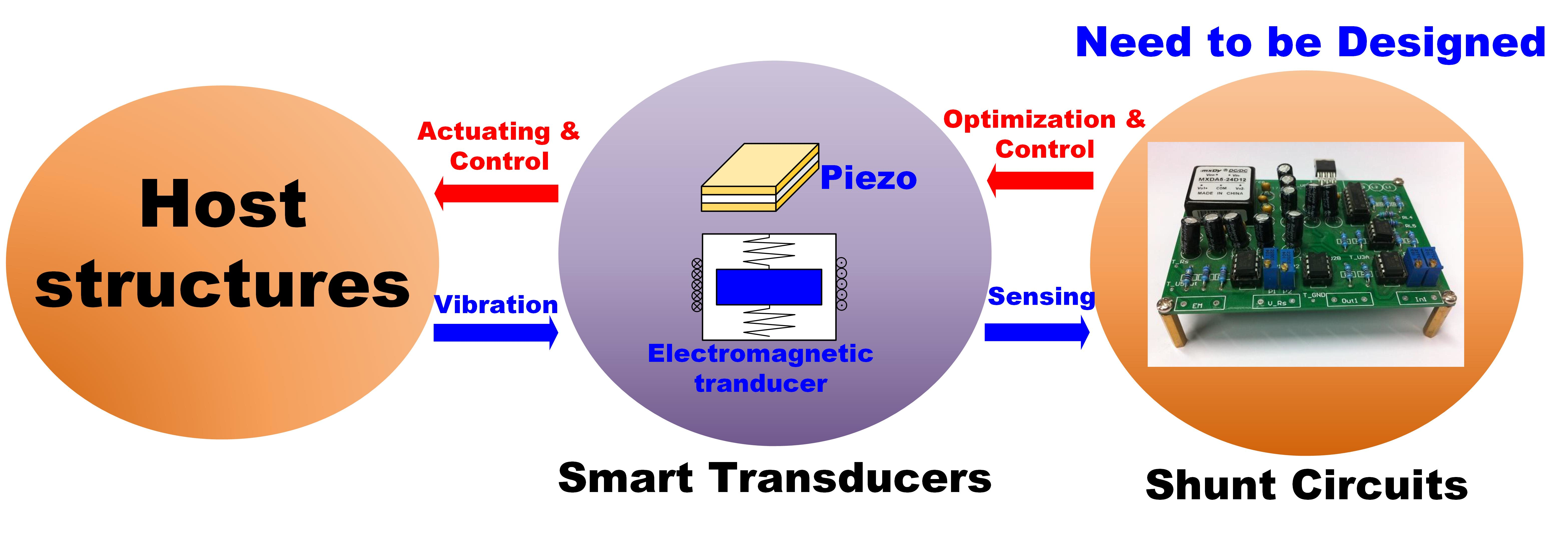
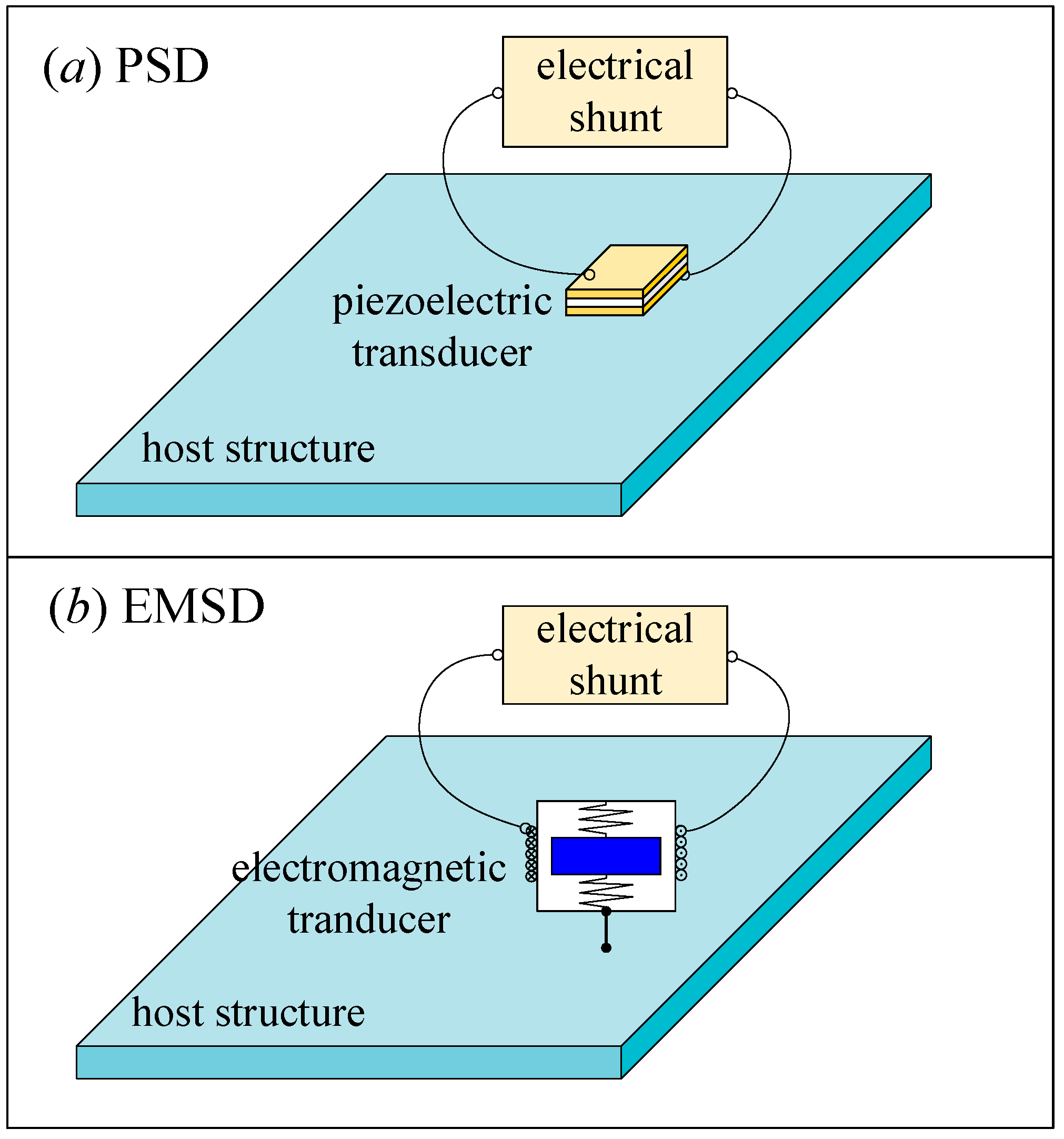
The shunt damping technique involves the connection of an electrical impedance to the terminals of a transducer. Over the past several years the shunt damping vibration control technique has been widely studied [27], and it can be mainly classified into two categories shown in Figure 1. The first one is piezoelectric shunt damping (PSD) [28]. The piezoelectric transducer is bonded to a host structure. As the host structure vibrates, the transducer produces an electricity. An external shunt circuit dissipates the electrical energy thereby dissipating the mechanical vibration energy, and the vibration of the host structure is suppressed. Figure 1a shows a simplified model of the PSD. The property of the shunt circuit determines the vibration control principle of the shunt damping. A resistor connected to the transducer dissipates the kinetic energy like a viscoelastic damper [29]. If the shunt consists of an inductor and a resistor in series, the shunt combined with the inherent capacitance of the piezoelectric transducer creates a damped electrical resonance that can be tuned so that the PSD acts as a damped vibration absorber [28].
Electromagnetic transducers can be used as actuators, sensors, or both. When current is applied to terminals of the electromagnetic transducer, a force is generated. Conversely, when a transducer experiences a velocity, an electromotive force (emf) is induced. Electromagnetic transducers exhibit these similar electromechanical properties but have considerably different physical and electrical characteristics compared to piezoelectric transducers. They have a much greater stroke, typically in the millimeter range. Consequently, in applications where piezoelectric transducers cannot be used, electromagnetic transducers may serve as an alternative choice [30]. Similar to PSD, when a shunt is connected across the terminals of the electromagnetic transducer, the kinetic energy of the vibrating structure can be dissipated through the coupling of the mechanical and electrical fields, the method is electromagnetic shunt damping [31], and a simplified model is shown in Figure 1b. After years of exploration, the parallel RLC shunt [32,33], the current flowing shunt [34], the synthetic shunt [35], the adaptive shunt [36] and the negative impedance shunt [37,38] have been studied to improve vibration control performance.
Similar to the electromagnetic transducer, the magnetostrictive transducer consists of a rod of magnetic material and a coil surrounding it. If a high magnetostrictive material, such as Terfenol-D, is used as a rod, the dynamic strain can be increased by 0.2%. Based on this characteristic, Fukada et al. [39] extended the shunt damping method from PSD to that of magnetostrictive transducers, and results implied that the stiffness can be controlled by connecting an external negative inductance circuit. Scheidler et al. [40,41] used this shunt as an electrically-controlled element to develop a variable stiffness spring based on magnetostrictive transducers.
After years of development, shunt damping technology can be classified as passive and active shunts according to the requirement of the external energy. Basically, passive shunts do not need an external energy, and these shunts mainly use the resistor, inductor, capacitor, and diode. However, active shunts require the external energy to drive and implement. In contrast to the traditional vibration control method, shunt damping is implemented using the same transducer.
The shunt damping technique has become a remarkable achievement after years of development and research. The fundamentals of shunt damping have been evaluated analytically and experimentally. The objective of the present review is to provide a comprehensive outline of the recent shunts to encompass the breadth of the work accomplished and provide sufficient attention to the critical results of these studies. In the following sections, this review displays a variety of the research investigations in shunt damping technique based on passive and active classification, either PSD or electromagnetic shunt damping (EMSD).
2. Fundamentals of the Piezoelectric and Electromagnetic Transducers
Shunt damping vibration control technology is a multi-physics coupling problem. It contains a transducer and a shunt circuit. This section summarizes the electrical fundamentals of the piezoelectric and electromagnetic transducers.
2.1. Piezoelectric Transducer
Since Pierre and Jacques Curie found the piezoelectric effect in 1880, piezoelectric ceramics has been widely applied to engineering structure. The phenomenon where a volume material undergoes shape transformation when exposed to an electric field is known as the piezoelectric effect. Conversely, the piezoelectric materials generate force or displacement output as the external charge is applied, which is the inverse piezoelectric effect. Therefore, piezoelectric ceramics is used as a sensor and an actuator in adaptive structures [42].
The electro-mechanical coupling of a piezoelectric transducer is [43,44],
where the indices and refer to different directions within the material coordinate system. and E are the strain, stress, electrical displacement (charge per unit area) and the electric field, respectively. and denote the elastic compliance, piezoelectric strain constant, and material permittivity, respectively.
The piezoelectric strain constant dmi is defined as the free strain developed in the ith direction per unit (going from 1 to 6) of applied electric field in the mth direction (going from 1 to 3). Assuming that a piezoelectric transducer is polarized along the z direction, the z directional strain is [45],
where V and h are the external voltage and the thickness of the piezoelectric ceramics. By definition, a voltage of the same polarity as the poling orientation leads to a positive strain or elongation. Elongation in the z direction implies a contraction in the x and y directions, thus d31 and d32 are opposite in sign to d33. The developed x and y directional strain are as
In electrical field, we have . Solving it for the electric field (the index subscripts have been dropped because this is now a scalar equation) results in . Multiplying by the thickness t of the piezoelectric results in an expression for the voltage across the piezoelectric material
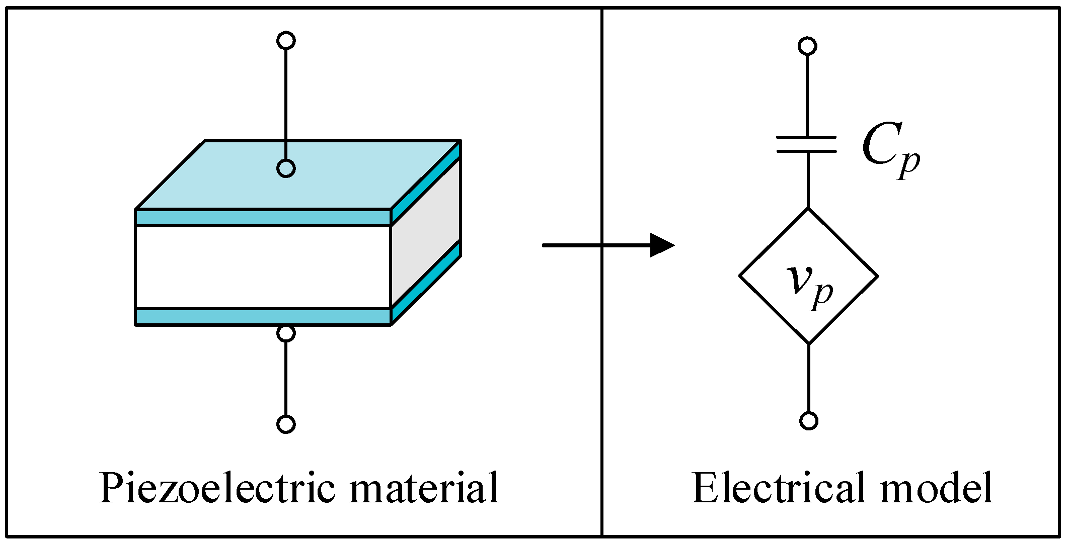
v is the voltage across the piezoelectric element. Define as the free charge area on the piezoelectric element, and the piezoelectric polarization charge per electrode area. The voltage can be written as [46]
where .The charge qp is proportional to the strain of the piezoelectric transducer and the charge qc is the applied or free charge. There is no charge applied on the piezoelectric transducer as to the shunt damping technology. Hence, the electrical circuit model is shown in Figure 2. The piezoelectric transducers is equivalent to a capacitor Cp with a voltage source vp as the structure vibrates [47].
2.2. Electromagnetic Transducer
Since Faraday discovered electromagnetic induction in 1831, electromagnetic devices have been widely used in engineering applications. The electromagnetic transducer consists of a coil and permanent magnets. An electromotive force (emf) is produced when there is the relative motion between the coil and magnets [48]. Inversely, the electromagnetic transducer generates the output force or displacement when the external controlled current is exerted. Under this circumstance, the transducer will be an actuator. The parameter design and optimization can improve the electromechanical coupling feature of an electromagnetic transducer, which will improve the vibration control performance [49,50]. The electromagnetic coupling coefficient can be obtained by theoretical analysis or experimental test.
As to a permanent magnet, the magnetic moment can be represented in terms of the volume current density jm and the surface current density km as [51]
where M is the magnetization vector, n is the unit vector normal to the surfaces of the magnet. Note that the volume current vanishes and some surface current densities that are normal to M become zero if the permanent magnet is uniformly magnetized. The magnetic flux density at any point P outside the magnet is the sum of the magnetic flux densities Bpi produced by each km,
where N is the number of km, and each Bpi can be obtained by the Biot–Savart law.
According to Faraday’s law, the induced emf can be obtained [52]
Disregarding the shape of the permanent magnet and coil, the emf and electromagnetic force can be formulated as [30,31,54]
where Ce and Cm are the electromagnetic coupling coefficient, and . v, I and Fe denote the relative velocity, the current flowing in the circuit, and the control force, respectively. Cm of the rectangle-shaped can be found in [52,53,55,56], the cylinder-shaped in [48,57], and the annular-shaped in [8,58,59,60,61].
It is suggested by (9) and (10) that an electromagnetic transducer can be electrically equivalent to an emf Ve, an inherent inductance Le and a resistance Re. The electrical model is shown in Figure 3.
2.3. Governing Equations of the Coupled System
For a single degree of freedom system, a discrete multimode degree of freedom system and a continuous system, it is easy to obtain the corresponding governing equation according to vibration theories [62,63,64]. The dynamic equations of the discrete systems are easy to analyze. However, methods for solving continuous structures are complicated. Some simple structures, such as an Euler-Bernoulli beam, a Kirchhoff plate and a shell, the governing equations can be derived if the boundary conditions are simple. In many cases, engineering structures are complicated and it is hard to obtain the theoretical model. Finite element method (FEM) can provide a feasible solution to obtain their modal characteristics. Either with the theoretical model or the finite element model, the system can be reduced to several single mode vibrations. Then the response of the system can be approximated using the modal superposition method. The process can be found in many professional books.
Because the shunted electromagnetic transducer adds a control force to the host structure, the governing equation can be obtained by combining the electrical equation of the circuit with the mechanical equation [28]. The governing equation presented by Neubauer et al. [65] and Kim et al. [66] can be used,
where the M, C and K denote the mass, damping and stiffness matrix of the host structure, respectively. Mp, Cs and Kp are the mass, damping and stiffness of piezoelectric transducers. F is the external force. is the electromechanical coupling matrix. The q and Q are the displacement vector of the host structure and the electrical charge vector. Cp is the inherent capacitance vector. L and R are the total inductance and resistance vector of the electrical circuit.
The governing equation of EMSD can be obtained by combing the structural and electrical equation together [34],
where ME and CE are the additional mass of the electromagnetic transducer and the electromagnetic shunt damping coefficient. M, C and K are same as that in (11). Then (11) and (12) can be unified as
where subscript index E denote the electrical domain. Veg and are the generalized voltage and electromechanical coupling coefficient. q and qE are the generalized displacement vector of structures and the charge vector.
3. Passive Shunt
The passive shunt mainly utilizes passive electronics, such as a resistor, a capacitor, and an inductor. Single mode and multimode vibration control can be achieved by designing the external shunt circuit. Piezoelectric and electromagnetic transducers are complementary with each other, which means that the series resonant shunt for the piezo is comparable to the parallel shunt of the electromagnet (and vice versa). In general, damping of dominant vibration modes of a flexible structure and their efficiency relies very much on the precise choosing of the shunt components. This section summarizes these linear shunts and calibration process.
3.1. Single Modal Vibration Control
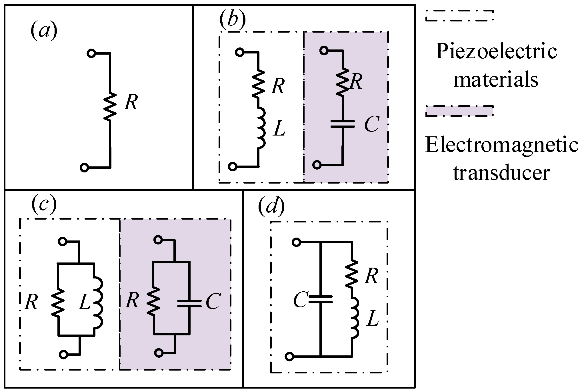
In 1979, Forward [27] carried out a preliminary experimental demonstration of the feasibility of using external electronic circuits to damp mechanical vibrations in optical systems. If the shunt is a simple resistor, the piezoelectric device will act similarly to viscoelastic damping treatment. Hagood and von Flotow [29] discussed two shunting circuits: the case of a resistor alone (shown in Figure 4a) and that of a resistor and inductor (in Figure 4b). The resistive shunt is a one-order electrical circuit nd the energy is dissipated at the resistor in form of heat. Therefore, the shunt is equivalent to an extremely light viscoelastic damping treatment that offers very little mechanical damping [67]. The piezoelectric transducer shunted with a resistor and an inductor [29] or the electromagnetic transducer shunted with a resistor and a capacitor [31] are the two-order circuit that can generate an electrical resonance. If the resonance of the electrical circuit is equal to that of the mechanical system, the circuit will be in resonance and a considerable control force will be generated to resist the vibration of the mechanical system. Then vibration is controlled. In principle, the two-order shunt is like a vibration absorber. Then fixed point theory can be used to optimize the parameters of the shunt. Kim et al. [68] used the electrical impedance model to tune the RL circuit. The optimal resistance of series shunt was obtained [69], which is , where m, k, and are the mass, stiffness, and the electromechanical coupling coefficient of the electromagnetic transducer, respectively. As to the piezoelectric transducer, Kozlowski et al. [70] studied RL shunted piezoelectric transducer and optimized the parameters. The optimal inductance and resistance are
where G is a modal constant. Soltani et al. [71] proposed an exact closed-form solution to the optimization of the piezoelectric material shunted with inductive-resistive circuits. This solution imposes exactly two equal peaks in the receptance function that are associated with the smallest possible vibration amplitude of the host structure. The single mode vibration control using a two-order shunt can generate an antiresonance effect to reduce the vibration of the host structure, and it has been successfully employed to reduce an HDD disk-spindle system [72,73], see Figure 5. The results showed that a RL shunt circuit can reduce the target mode vibration by 60%. Schoeftner and Irschik [74] established a passive smart beam using a shaped piezoelectric transducer and an RL circuit.
The previous studies on the single mode shunt focused on the design and optimization of the circuit, such as the parallel shunt, series shunt, and series-parallel shunt. Wu [75] proposed the parallel RL shunt circuit shown in Figure 4c, the similar shunt can be found in [76,77,78]. Guo and Jiang [79] utilized the R-L shunt to construct a modal piezoelectric transducer to control vibrations of a truss-cored sandwich panel. The series and parallel resonant shunts can obtain similar vibration control performance, but the parallel one is less sensitive to the optimal resistance. Figure 4d is an RL-C parallel shunt circuit [47]. Sun et al. [80] studied vibration suppression of a hard disk driver actuator arm by using serial RL and parallel R-L shunts. Al these results showed that a good one mode vibration can be achieved using the resonant shunt.
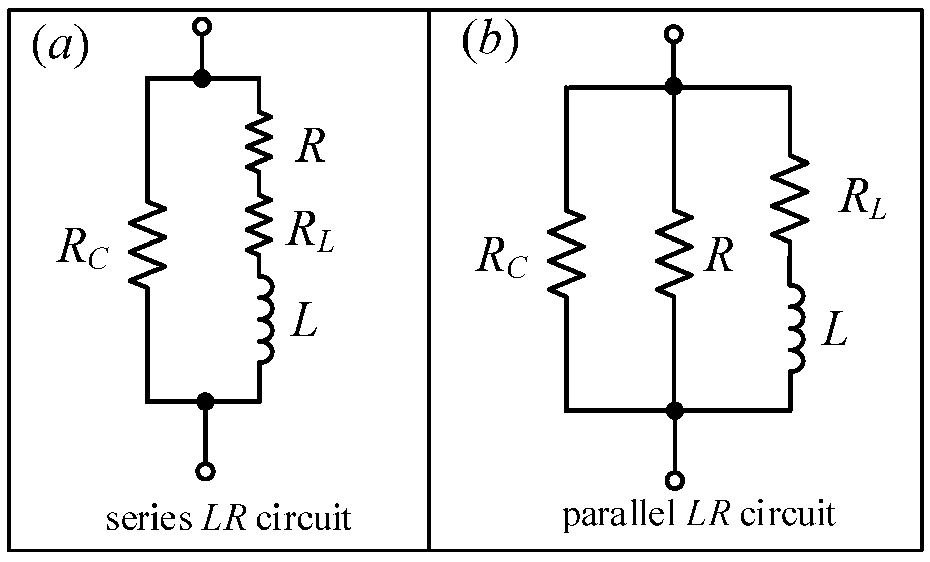
Yamada et al. [81] derived governing equations according to the equilibrium of force principle and used an equivalent mechanical model of a piezoelectric transducer. Series RL circuit (see Figure 4b) and parallel LR circuit (see Figure 4c) are used. According to fixed points theory, the analytical optimal natural frequency ratio and the resistance ratio of the RL shunts are determined in terms of displacement, velocity, and acceleration. The optimum tuning parameters in terms of displacement are
The optimum tuning parameters in terms of velocity are
The optimum tuning parameters in terms of acceleration are
where , Θ is the modal electromechanical coupling coefficient. The optimized inductance and resistance can be obtained using the optimum fAopt and ζAopt. These three terms of expressions provide a feasible way to optimize RL shunts.
In application, piezoelectric elements dissipate some energy due to dielectric loss. This phenomenon is caused by the relaxation time of polarization. Yamada et al. [81] considered that dielectric loss can be expressed by a parallel resistance RC in the equivalent circuit,
where δ is the dielectric loss factor. As RC is ∞, there is no energy loss. Similarly, inductors also dissipate energy for they have not only inductance but also internal resistance that can dissipate the energy. Figure 6 shows the improved series and parallel RL circuit considering RC. From (15)–(17), the optimal resistance ratios in the ideal models are almost equal even although these expressions are significantly different. It suggests that the ratio does not rely on the position of the resistance. Hence, the total resistance ratios in the practical models should be tuned to be close to that in the ideal models.
The abovementioned series and parallel RL shunts mainly used fixed points theory to find the optimal maximum modal damping. However, the former is suboptimal near resonance due to constructive interference of the two modes with identical frequency, and the latter leads to reduced implemented damping. Hogsberg and Krenk [82,83,84] proposed an explicit pole placement–based design procedure that relies on equal modal damping and sufficient separation of the complex poles to avoid constructive interference of the two modes. The optimal parameters are [82]
where , , . , w and u are the piezoelectric coupling coefficient, the deformation of the piezoelectric transducer and the modal shape vector. Compared with fixed points theory, the explicit pole calibration leads to a balanced compromise between large modal damping and effective response reduction with limited damping effort. Furthermore, Krenk and Hogsberg [85] provided a unified presentation using the equal modal damping principle and calibrated the resonant control for different control formats, based on velocity, acceleration–position or position feedback.
By extending the local piezoelectric transducer displacement by two additional terms, the flexibility and inertia contributions from the residual vibration modes that are not directly addressed by the shunt damping, Hogsberg and Krenk [86] improved the calibration principle.
3.2. Multimodal Vibration Control
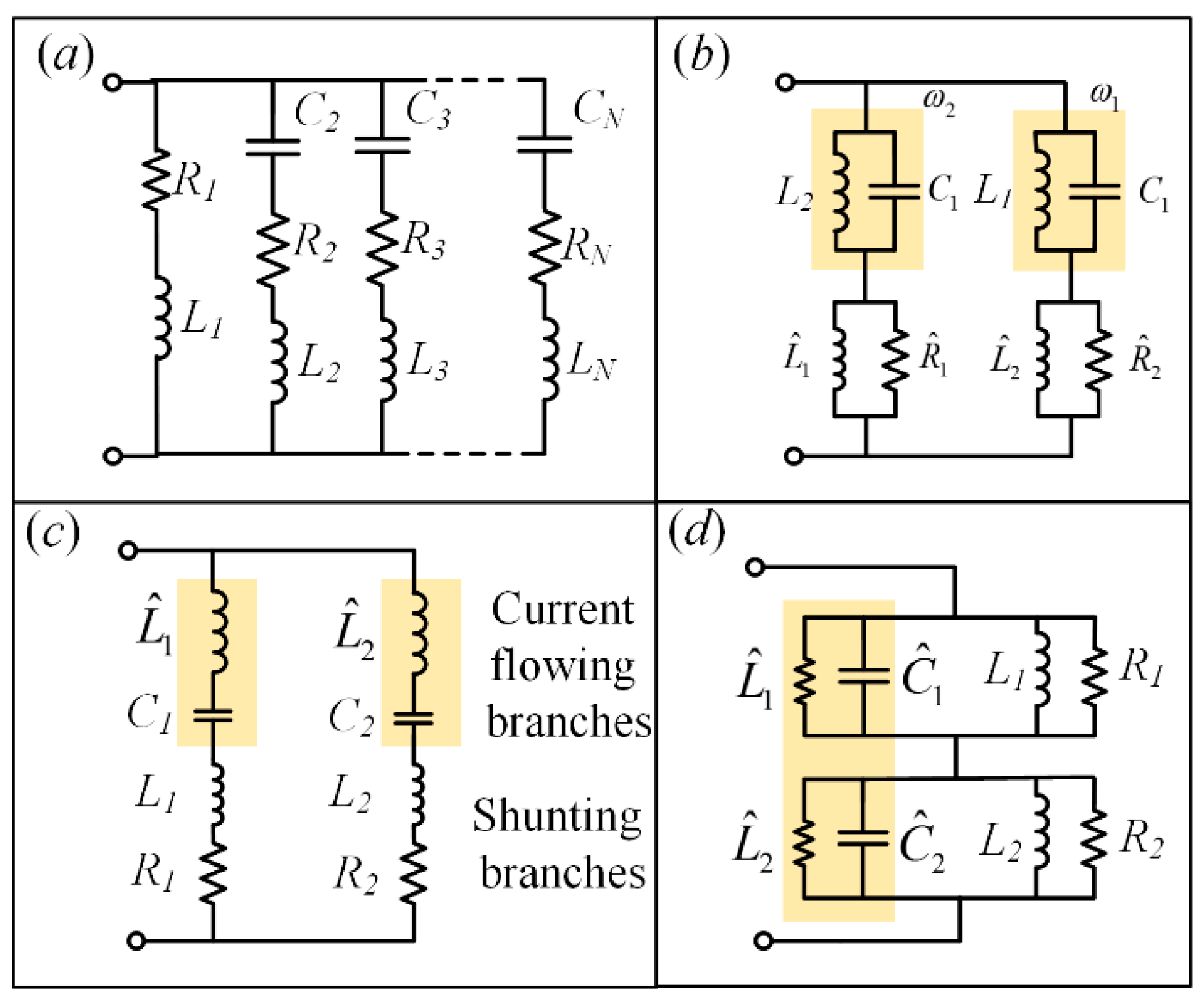
In most cases, the single mode shunt is not enough for a multimode system. Hollkamp [28] expanded the single mode shunt damping theory and discussed the effect of the resonant circuit shunted piezoelectrics on a beam, so that a single piezoelectric element can be used to suppress multiple modes. Additional electronic components have been added to the shunt to increase the number of electrical resonances. A capacitor-resistor-inductor shunt is added for each additional structural resonance, as shown in Figure 7a. The electrical impedance of the shunt is
It is difficult to tune the circuit without analytical predictions, since each individual branch of shunt cannot be considered an individual single-mode shunt. Tuning one electrical resonance to suppress a particular mode will detune the rest of the circuit. This shunt is applied to a cantilevered beam and is demonstrated experimentally as a two-mode device. Peak reductions in the second and third bending modes are reduced by 19 dB and 12 dB, respectively. This kind of shunt is called a Hollkamp shunt. However, the optimal inductances for the first mode (L1 = 43.4H, L2 = 33.5H) are too big and make them hard to implement.
Another multi-mode shunt that employs a blocking circuit in series with one parallel resistor-inductor shunt circuit is designed to control one modal vibration [75,87,88]. The blocking circuit consists of one parallel antiresonant circuit or a series of them. The number of antiresonant circuits determines the modes of structural vibration to be controlled. Figure 7b shows the schematic of two mode shunt damping at ω1 and ω2. The first branch, with shunt inductor and resistor , is inserted with a blocking circuit that consists of a parallel capacitor and inductor C2-L2, whose electrical impedance is designed to approach infinity at the second branch frequency ω2, where . The second branch also utilizes an antiresonant circuit, and . In this way, the remaining branch is effectively open circuit at the resonance frequency of each parallel branch.
The total inductance in each branch circuit has to remain the same after the blocking circuit is inserted since the branch circuit has to shunt-damp the corresponding modal vibration. Consequently, the inductance value and of the new shunt has to be adjusted,
Figure 7c is the current-flowing shunt, which needs one parallel branch to control each structural mode. The current flowing shunt is similar in nature to the current blocking shunt. Instead of preventing the current flowing at the natural frequency ωn, the current flowing shunt allows the current to flow [89]. The shaded current flowing network in ith branch is tuned to approximate a short circuit at the target resonance frequency whilst approximating an open circuit at the frequencies of adjacent branches. The remaining inductor and resistor in each branch are tuned to damp the ith target structural mode in a manner analogous to single-mode shunt damping. Theoretically, the flowing shunt can achieve n mode vibration control as n branch circuits connect to the piezoelectric patches. The inductance of the shunt branches is
If the capacitance of the current flowing branches is , the inductance of the current flowing branches is
The current-flowing shunt can be modified and simplified by combining values of series inductor together, e.g., [90]. The current-flowing network decouples the multi-mode problem into a number of approximately independent single-mode problems. Unlike the current-blocking technique, the order of each current-flowing branch does not increase, with the number of modes to be controlled simultaneously increasing. Moreover, the current-flowing shunt requires less components and gracefully extends to damp a large number of modes simultaneously. The vibration control performance of a plate shows that the current-flowing shunt can suppress the first five resonant amplitudes by 3.8, 10.1, 12.8, 13.2, and 14.7 dB, respectively. The corresponding optimal inductance of the first five mode vibration are 1986.3H, 491.1H, 259.2H, 142.2H, and 71.1H, respectively. Fleming and Moheimani [91] considered a controlled source that establishes the relationship between the controlled current and voltage. The impedance of the controlled source can be regarded as the equivalent impedance of the shunt circuit. Hence, an arbitrary impedance can be realized.
Cheng and Oh [34] extended the current flowing shunt damping from the piezo to the electromagnetics. An electromagnetic coil was bonded on the beam and a fixed permanent magnet was placed under the bottom of the coil. The terminals of the coil connected to the current-flowing shunt circuit to control two modal vibrations. Similar to the piezoelectric shunt, the current-flowing shunted electromagnetic of a single mode branch is the series of capacitor-inductor-resistor. The multiple mode vibration can be controlled by adding parallel shunts. The optimal frequency and the optimal inductance of the shunt were obtained according to fixed points theory, which are
where is the electromagnetic coupling coefficient. Mi, Ki and are the modal mass, stiffness and shape vector of the system, respectively. L1 is the inductance of the shunt for mode one. The experiment results showed that the first and second mode amplitudes were reduced by 25 and 10 dB.
The passive multimode shunts mainly use electrical resonant characteristics to produce the multimode vibration control performance, e.g., current-flowing, current-blocking. Figure 7d presents another multimode shunt using a series-parallel circuit, which can reduce inductance of the shunt [92]. Each network in series contains two sub-networks: a current-blocking network , and a parallel single-mode damping network . The two networks are tuned to the same target resonance frequency ωi. Under this frequency, the current-blocking network has an extremely large impedance. All of the remaining current-blocking networks, tuned to other structural resonance frequencies, have a low impedance at ωi. The voltage applied at the terminals results in a current that flows freely through the detuned current-blocking networks but is forced to flow through the active damping network. In this way, the circuit is decoupled so that each damping network can be tuned individually to a target resonance frequency. Li can be calculated according to (22), and (23).
The series-parallel shunt offers no great advantage over comparable techniques. Benefits arise from a suitable choice in the arbitrary capacitances Ci. The recommended capacitance value is 10–20 times that of the piezoelectric capacitance. In this case, the current blocking inductors become significantly smaller than the damping inductors. When the circuit is simplified by combining current-blocking inductors in each series network, the resulting single inductor is a fraction of that required in other single- or multi-mode circuits.
It should be noted that there is another piezoelectric transducer with shaped electrodes that has attracted attention. Modal control and spatial filtering technologies can filter out undesirable and uncontrollable modes over the bandwidth to increase the robustness and stability of the controlled structural system. The idea provides a novel approach to design a resonant shunt. Vasques [93] employed shaped electrodes to develop a two-layered RL shunted piezo smart Euler–Bernoulli beam. The results demonstrated that the capacitance for the modal case is mode dependent and is always lower than that for uniform electrodes. As a consequence, the optimal resistor and inductance values are higher than those needed for the uniform electrode cases, which is a shortcoming of the modal approach.
In summary, the passive shunts mainly utilized a resonant circuit to construct an electrical absorber to reduce the structural vibration. Either PSD or EMSD used fixed points theory to optimize the parameters of the shunt, such as the inductance, the capacitance, and the resistance. All of them are efficient and capable of suppressing the target mode vibration of a flexible structure. However, problems arise when the lower resonant frequencies of a flexible structure are too small. In this case the optimal inductance [90] or capacitance will have a bigger value and make it impossible to implement. On the other hand, there is a common drawback for a resonant type shunt circuit: the structural natural frequencies shifts as there is a stiffness variation, which will evitable make the shunt circuit detune either the single mode or a multimode. Therefore, active shunts are essential to compensate for these uncertainties.
4. Active Shunt
Active shunts are those where external electrical energy is needed. Compared to the passive shunt, the active one utilizes controlled electronics, e.g., operational amplifiers, transistors, electronic switches, to realize vibration control. In the view of the control system, the shunt circuit can be regarded as a controller that establishes the relationship between the control current and voltage, . An arbitrary impedance Z(s) can be constructed using a controlled current I(s) or voltage source Vz(s), thus, the design problem is reduced to a standard linear regulator problem enabling the application of standard synthesis techniques. Fleming et al. [94,95] proposed active LQR, H2, and H∞ shunt control, which can be easily applied to achieve a suitable impedance. These kinds of impedances are unrestricted in structure, and can be designed to meet any performance specification set within the flexibility of the synthesis process. The active shunt impedances are remarkably insensitive to variation in the structural resonance frequencies. The schematic of the LQR and H∞ shunts can be found in [95]. These algorithms can be implemented by using a dSPACE controller. However, it has turned out that a very well identified model of the system is needed and the control design is not straightforward due to the highly reactive impedance of the transducer.
The main advantage of the active shunt is to achieve broadband or multimode vibration control. The negative impedance shunt circuit is able to cancel the inherent electrical impedance of the smart transducer. Figure 8a shows a kind of negative impedance converter (NIC) [96,97]. The equivalent impedance is
If Z1 = Z2= R, Z3 = CS, the shunt will be a negative capacitance converter, where R and CS denote the resistance and the capacitance of the shunt, respectively. Behrens et al. [98] studied the effect of a negative capacitance controller theoretically and then validated it experimentally on a piezoelectric laminated simply supported plate. A single piezoelectric transducer was used to dampen multi-mode vibration. Experimental resonant amplitudes for the first to sixth modes were successfully reduced by 5.8 dB, 20.1 dB, 18.2 dB, 3.8 dB, 16.7 dB, and 17.2 dB. Park et al. [99] considered the stiffness ratio and loss factor with respect to the non-dimensional frequency to describe the characteristic behaviors of a piezoelectric damper connected to a series and a parallel resistor-negative capacitor shunt circuit. Neubauer et al. [65] analyzed the effect of negative capacitance shunted piezoelectric transducers in damping and absorbing systems. L-network, R-network, RL-network, C-network, LC-network, RC-network, and LRC-network were investigated theoretically, and the corresponding optimal tuning frequency and resistance were listed. It can be shown that the damping performance is increased significantly by adding a negative capacitance to the system. Marneffe and Preumont [37] discussed series and parallel negative capacitance, shown in Figure 8b. The open-loop frequency response function was used to draw a Nyquist plot to judge the stability of the two kinds of negative capacitance shunts. The experimental results showed that the parallel and series negative resistance can reduce the vibration of the struct by 18.4 dB and 21.9 dB. The series one has a relatively better robustness than the parallel one. Manzoni et al. [100] discussed the values of electric elements composing the negative capacitance to improve vibration reduction efficiency and to avoid instability at low frequency.
Ji et al. [38] used a negative capacitance in synchronized switching damping (SSD) instead of an inductance in the traditional SSD technique. Therefore, there was no resonance in the circuit. The equivalent circuit of a synchronized switch damping technique based on negative capacitance system (SSDNC) is purely capacitive. Moreover, the voltage applied on the piezoelectric element is inverted by the negative capacitance. Mokrani et al. [101] also added a negative capacitance to the resonant circuit to enhance the performance of the SSD. Considering the sensitivity and instability of the negative capacitance circuit, measurement and quantification of the power within the shunt has been difficult to obtain. The method was verified using a cantilever beam. The results showed that a pure SSD shunt can reduce the vibration by 25.2 dB, and SSD with negative capacitance can reduce the vibration by 31 dB. Beck et al. [102] discussed the power output and efficiency of a negative capacitance shunt for vibration control of a flexural system. The power can be expressed in terms of the shunt impedance and the strain-induced voltage Ve
where Zs is the total impedance of the shunt.
In recent years, research on the negative capacitance shunted piezoelectric transducer has been increasing. Qureshi et al. [103] studied the negative capacitance–inductance shunt and modeled the behavior of a negative capacitance–inductance shunt in terms of power output and efficiency. Hereafter, a new self-powered SSD technique was proposed in which the inductance in the previous self-powered SSD techniques was replaced with a negative capacitance thus making the circuit capacitive without generating resonance. The optimum damping performance is obtained by keeping the value of negative capacitance slightly greater than the inherent capacitance of the piezoelectric patch. Rogerio et al. [104] proposed a new tuning method for shunt damping with a series resistance, inductance and negative capacitance shunted piezoelectric transducer.
The part above summarizes the negative capacitance shunt in piezoelectric shunt damping vibration control. As to the electromagnetic transducer, the moving coil in the magnetic field can be electrically equivalent to an emf Ve, a resistance Re and an inductance Le. Therefore, the negative resistance can be used to cancel out the inherent resistance of the coil to improve the vibration control performance of the electromagnetic transducer. The vibration control principle of the negative resistance electromagnetic shunt damping (NR-EMSD) is similar to that of the negative capacitance piezoelectric shunt damping. However, NR-EMSD has special features for the difference between electromagnetic and piezoelectric transducers.
A negative impedance converter can be used to realize a negative resistance. Shown in Figure 8a, the shunt will be a negative resistance as Z1 = Z1 = R, Z3 = RS. The negative resistance can be changed by changing the resistance of Z3. On the other hand, a synthetic impedance is able to construct an arbitrary impedance [35,105]. Based on this traditional negative resistance converter, Stabile et al. [106] developed a 2-collinear-DoF strut for the micro-vibration isolation of a spacecraft.
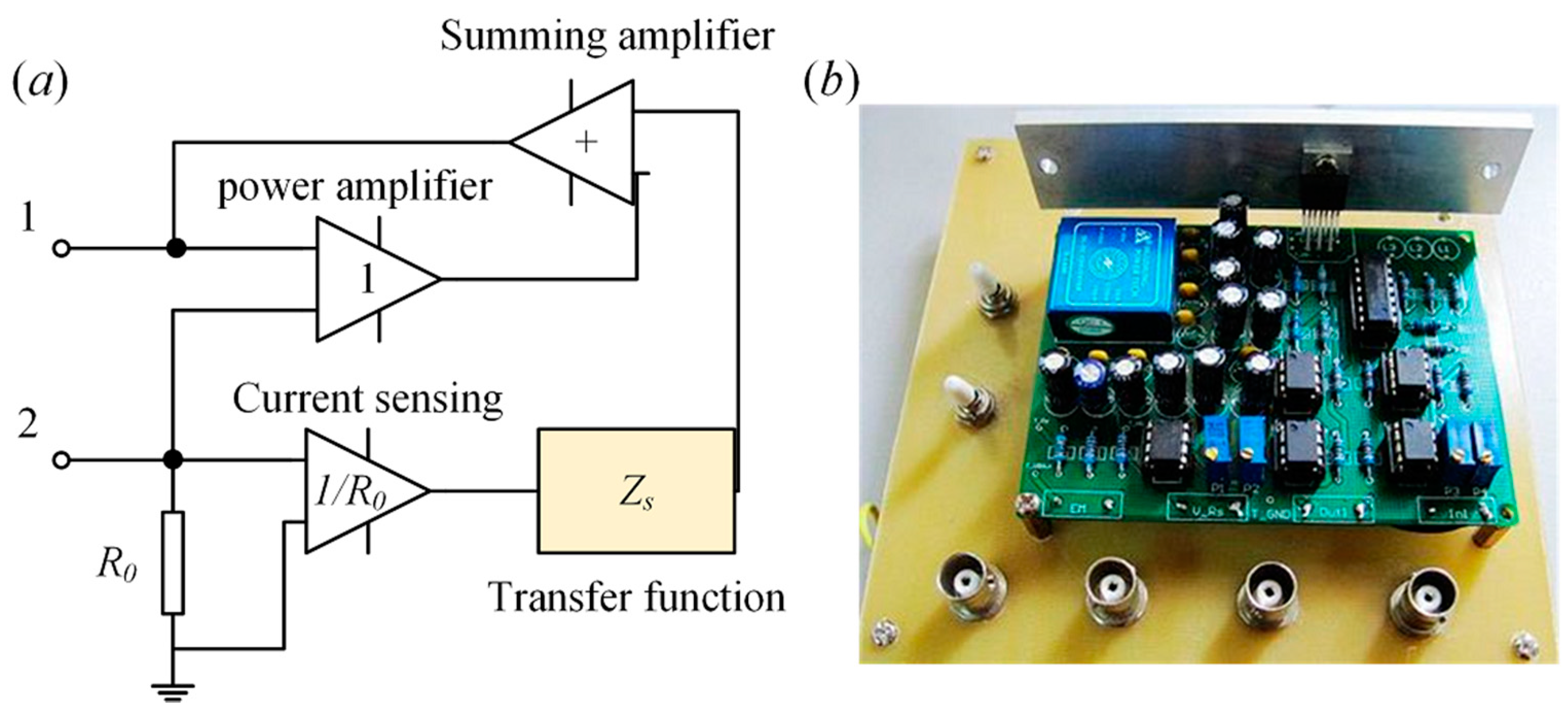
Figure 9a shows a kind of synthetic shunt impedance converter. The circuit works in three stages: the first is a current sensing stage; the current is multiplied by the desired impedance Zs that is defined by a digital controller dSPACE. The voltage is then added to give the voltage across the terminals of the coil. This voltage is passed through an additional power amplifier and input to terminals of the electromagnet in the physical system [107]. Figure 9b presents a prototype of the shunt.
Using the synthetic shunt impedance shown in Figure 9a, Niu et al. [52] proposed a capacitor- matching-inductance method and a negative resistive capacitor-matching-inductance method. In the work, Zs was replaced by the transfer function , and the electrical governing equation of the EMSD system is
where the transfer function of the analog impedance was implemented using the dSPACE system. Therefore, Rt and Ct can be adjusted conveniently. If Rt is negative, the analog shunt impedance will produce negative resistance. Using this shunt, Yan et al. [53] designed a negative resistance shunted electromagnetic isolator by replacing Zs with Rs. Fully theoretical modeling and experimental investigation of a single degree of freedom system have been carried out. It was found that negative resistance shunted electromagnetic damping has both electromagnetic damping CEMSD and electromagnetic stiffness KEMSD [107]. The two coefficients are
Rs cancels the inherent resistance of the coils Re, and as a result CEMSD will increase, which make it feasible to suppress the vibration. Furthermore, the natural frequency will shift toward a higher value with the increase of KEMSD. Herein, the vibration of the beam [55] and plate [108] were also discussed. The results pointed out that the negative resistance shunt is capable of isolating multimode vibrations.
In order to reduce the electromagnetic shunt stiffness KEMSD brought by the negative resistance, Zhang et al. [56] proposed negative inductance negative resistance shunted electromagnetic damping. The negative inductance cancels the inherent inductance of the coil, and the impedance of the circuit consisting of the coils and shunt will be a pure resistance. Then, the current of the closed circuit will be frequency independent as the inductance of the shunt and the coil are equal to each other. The experimental result demonstrated that this negative inductance negative resistance shunt attenuated the multimodal vibration of the plate. Moreover, the electromagnetic shunt stiffness decreased when negative inductance was used. Furthermore, the negative resistance shunt can generate a relative broadband damping effect. Yan et al. [60,61] applied the negative impedance shunt to an electromagnetic absorber and discussed the multimodal vibration absorption of this shunt. The experimental results implied that the first three mode vibrations can be reduced by 15.11, 16.08, and 11.45 dB using negative resistance (NR) absorber, and 20.57, 21.75, and 15.33 dB amplitude reductions were achieved using negative inductance negative resistance (NINR) absorber. Both the two shunts are capable of suppressing multimode vibration efficiently. The negative inductance negative resistance shunt has a better absorption effectiveness at high frequency than the pure negative resistance shunt. It also demonstrated that the negative impedance is less sensitive to the frequency shift than resonant shunts.
Furthermore, Fukada et al. [39] presented the basic designs of the magnetostrictive actuator connected to the negative inductance shunt. The shunt is implemented using the NIC that can be found in Figure 8a. An improved circuit has been constructed shown in Figure 10. The inductance ratio is given as
Under dynamical vibration, the actuator should have a loss factor and the inductance can be expressed by the complex quantity , where . It is observed that the resonant frequency of the system decreases or increases, depending on the type of negative inductance shunt. After that, Scheidler et al. [40] used a negative inductance shunt as an electrically-controlled element to develop a variable-stiffness spring based on magnetostrictive transducers.
There is an alternative active shunt called the active elasticity control (AEC) method proposed by Date et al. [109]. It is another name for the active shunt, but it has special design analysis procedures. The AEC is realized by connecting the piezoelectric element to an external feedback circuit. The induced voltage of piezoelectric transducers generates secondary deformation due to the inverse effect. Because the induced voltage depends on the internal and external impedances, the change of the external impedance affects the additional deformation of the transducer due to the inverse effect. Then the total deformation can be controlled by controlling the impedance of the external shunt. The parameter that controls the effective stiffness of the piezoelectric transducer is the capacitance. If the external shunt circuit with impedance Zext connects to a piezoelectric transducer, the ratio of the impedance of the inherent capacitance Cp and Zext is Date et al. [109] suggested that the elastic compliance can be deduced according to (1),
where . If a negative capacitance shown in Figure 9 is used, the dynamic elastic constant of piezoelectric transducers will be modified. When the negative capacitance shunt was used, the elastic constant increased significantly, and decreased when the equivalent capacitance of the circuit was equal to that of the transducer. When an inductance shunt was used, the elastic constant exhibits resonance and anti-resonance against frequency around the electrical resonant frequency of the circuit. The elastic loss was significantly modified by changing the compensatory resistance.
The AEC method that controlled the elastic property of piezoelectric transducers has become the basis of smart structural vibration control, and it provides a possibility to design new vibration and noise control devices. Morky et al. [110,111] carried out the theoretical analysis of AEC devices, and the result of negative capacitance shunted AEC showed that a 35 dB transmission loss reduction in the frequency range from 100 Hz to 2 kHz was achieved. After that, various applications of AEC were demonstrated by Fukada et al. [112]. Sluka et al. [113] designed a vibration isolation system utilizing AEC to control the effective elastic stiffness of piezoelectric transducer. An additional feedback control was introduced to realize the automatic stabilization and adjustment of the negative capacitance. Based on this work, Sluka et al. [114] proposed an adaptive negative capacitance shunt to enhance operational stability of a sound-shielding system. Steiger and Mokrý [115] established the effective anisotropic Young’s modulus of negative capacitance using finite element modeling. The AEC method provides an alternative approach to the design shunt damping devices and can be very efficient in solving complicated vibration and noise problems.
Resonant shunts reduce the vibration by generating electrical antiresonance, while active shunts suppress structural vibrations by increasing the actuating force that is validated by decreasing the total impedance of the electrical circuit. Active shunts overcome the high sensibility of the tuning frequency of the control circuit, and are possible in suppressing a broadband vibration.
5. Nonlinear Shunt
In some special conditions, the mass, stiffness or damping of a mechanical system may be state-switchable when a structural system suffers irrespective instantaneous changes. This state will result in a large response. Davis et al. [116] presented a kind of switchable capacitor shunt that can change the stiffness of the actuator so as to change the natural frequency of the system. Thus, the vibration control can be achieved by avoiding the resonance shown in Figure 11a. Cunefare et al. [117] proposed a switchable stiffness element that is obtained through control of the termination impedance of piezoelectric stiffness elements. The change of the stiffness results in the change of the resonant frequencies of the system by incorporating piezoelectric stiffness elements as part of the spring element of a vibration absorber [118]. Using two discrete stiffness states, ks1 and ks2, with ks1 < ks2, two resonance frequencies of the absorber ωs1 and ωs2 are obtained. Consequently, this switch impedance shunt can change the stiffness of the absorber to change the vibration control performance. Corr et al. [119] developed a switching R-L shunted piezoelectric vibration control method, which works by briefly connecting a series resistor inductor shunt to the piezoelectric actuator to apply the necessary signed charge to allow energy dissipation (shown in Figure 11b). As with introducing the RL shunt, the magnitude of the charge applied to the piezoelectric actuator can be greater than the magnitude of the generated charge.
The state switching shunt vibration control technique utilizes the concept of energy dissipation through electromechanical materials, which have the ability to change their equivalent effective stiffness. For example, as the piezoelectric transducer is in an open circuit state, it possesses a particular stiffness. Conversely, as the transducer is in short state, it possesses a different stiffness, particularly, a relatively low stiffness. Consequently, many other state switchable shunts were investigated to switch the stiffness or the damping of the system. Figure 11 shows some kinds of switchable shunt circuits that have been thoroughly discussed: synchronized switched damping on a resistance (SSDS), synchronized switched damping on an inductance (SSDI), synchronized switched damping on a voltage source (SSDV), synchronized switched damping on negative capacitance (SSDNC), and synchronized switched damping on negative capacitance and inductance (SSDNCI) [120]. The classical SSD remains in an open circuit for the majority of the vibration cycle and switches briefly to a shunt circuit at every extremum displacement. These researches pointed out that the switch timing was only optimal for excitation exactly at resonance. Christopher et al. [121] proposed a self-tuning approach that implemented the more general optimal switch timing for synchronized switch damping on an inductor without needing any knowledge of the system parameters. In order to improve the damping performance, Han et al. [122] connected SSDI circuit in parallel to a negative capacitance.
The implementation of the nonlinear switchable shunts seem not to require external power for operation for the switches can be realized with MOSFETs that require almost no power to be switched. An additional piezoelectric transducer can supply the small amount of power required to switch the MOSFETs.
6. Adaptive Shunt
According to the previous summaries above, it can be deduced that shunt damping technology is a simple and effective vibration control method that can be applied for the various situations. However, in practical applications, the change of the temperature and the stiffness can result in significant movement of the structural resonance frequencies. Moreover, the capacitance of a piezo and the inductance of the electromagnetic transducer may have variation. Such variations can severely reduce shunt damping performance because the electrical impedance remains tuned to the nominal resonance frequencies.
Niederberger et al. [123] presented an adaptation R-L shunted piezoelectric transducer to compensate variation of the natural frequency. The adaptation law was based on the phase match, shown in Figure 12a. The tuning direction of this adaptation law was obtained by detecting the phase shift between the velocity of the mechanical structure and the current in the shunt circuit. The phase of this transfer function is . is the optimal tuning for the modal frequency, the phase will be π/2. The tuning adaptation law was obtained by detecting the phase shift between the velocity of the mechanical structure and the current in the shunt circuit. As the exact value of the phase for this technique is not required, one can reduce the adaptation problem to multiplication and integration of current and velocity. The adaptive R-L resonant shunt overcomes the sensitivity of the traditional resonant shunt to the structural natural frequency. The results showed that: (1) when the temperature of piezo was changed from 27° Celsius to 15° Celsius, the adaptive R-L shunt can keep the same amplitude reduction (−11 dB). Conversely, vibration reduction drops by 6.5 dB when an R-L shunt was used; (2) When the natural frequency was changed from 383 Hz to 375 Hz, a considerable amplitude reduction was also obtained. These results showed the robustness of the adaptive shunt when subjected to a variable situation.
The passive multimodal shunts mainly utilize damped electrical resonance that consists of the inherent inductance or capacitance of the transducer and RLC network to tune the structural vibration. Niederberger et al. [124] also discussed an online adaptation of multi-mode resonant shunts based on the phase shift method. Figure 12b is the principle of the adaptive inductance shunt that employs the multimode current-flowing circuit. The series CFi−LFi network has zero impedance for and has high impedance at all other frequencies. The plate structure results implied that considerable control performance can be achieved despite the change of the modal frequencies and capacitance of the piezo.
Fleming et al. [36] introduced an online adaptation of current-blocking and current-flowing shunts (shown in Figure 7b,c)). The system was implemented using synthetic impedance (presented in Figure 9) along with time varying transfer functions to alter the parameters of a shunt circuit in real time. Note that the impedance of the shunt is Z(s), the adaptive shunt synthesizes the impedance Z(s) twice: first, to implement the shunt damping circuit, and second to reconstruct the performance signal Vp. Experimental results showed reliable estimation of the performance functions, optimal tuning of the circuit parameters, and satisfactory mis-adjustment. The second and third modal vibrations were reduced by 22 and 19 dB. Although both current blocking and current flowing shunts provided similar performance, the current flowing technique requires a lower-order admittance transfer function, and is easily parameterized in terms of the branch resonance frequencies. These reasons made the current flowing technique an ideal candidate for damping a large number of modes.
Hereafter, Niederberger et al. [54] also studied the adaptive electromagnetic shunt damping. A single mode RC resonant shunt controller was developed as shown in Figure 13. The impedance of the shunt Z(s) is . The controller will be
The optimal damping of the mechanical resonance ωn can be achieved if the RC shunt is tuned to . The optimal capacitance is
The adaptive RC shunt was verified experimentally on a single degree of freedom system. A vibration suppression of 22.75 dB was obtained during nominal operating condition. The relative phase adaptation was found to converge seven times faster as it is subjected to the induced changes in operating conditions.
Resonant shunts have been successfully used to reduce structural vibration and this kind of shunt can be regarded as an electrical absorber. Yan et al. [53] pointed out that the negative resistance shunted electromagnetic damper can produce electromagnetic shunt damping and electromagnetic shunt stiffness effect to influence o the inherent inductance of the coil. On the one hand, the electromagnetic shunt stiffness affects the vibration control effectiveness. On the other hand, it can be used to change or adjust the stiffness of the absorber. McDaid et al. [107] introduced o electromagnetic shunt damping into a dynamic absorber to provide controllable effective mechanical stiffness and damping. The expression of the damping and stiffness can be found in (28). A model-based feedforward controller was designed to adapt the resistance and capacitance to ensure the tuned frequency of the vibration absorber. The synthetic shunt impedance circuit (shown in Figure 9) was used to implement it. As the absorber is sensitive, the frequency can be estimated as
Adaptive electromagnetic shunt damping shows a good response over a relative wide range of excitation frequencies (90–100 Hz). The adaptive controller provides a useful way to broaden the bandwidth of the absorber. Based on this technique, MacDaid et al. [125] used three different feedback algorithms, linear, nonlinear, polynomial, and fuzzy logic control, to compensate for errors in model parameters, and estimate the excitation frequency and environmental changes. The experimental results implied that the linear controller is unreliable, but the polynomial and fuzzy controllers work effectively. The adaptive controller can successfully adapt the system to track a variable excitation frequency while being robust with regard to errors or changes in system parameters and provides guaranteed stability in operation.
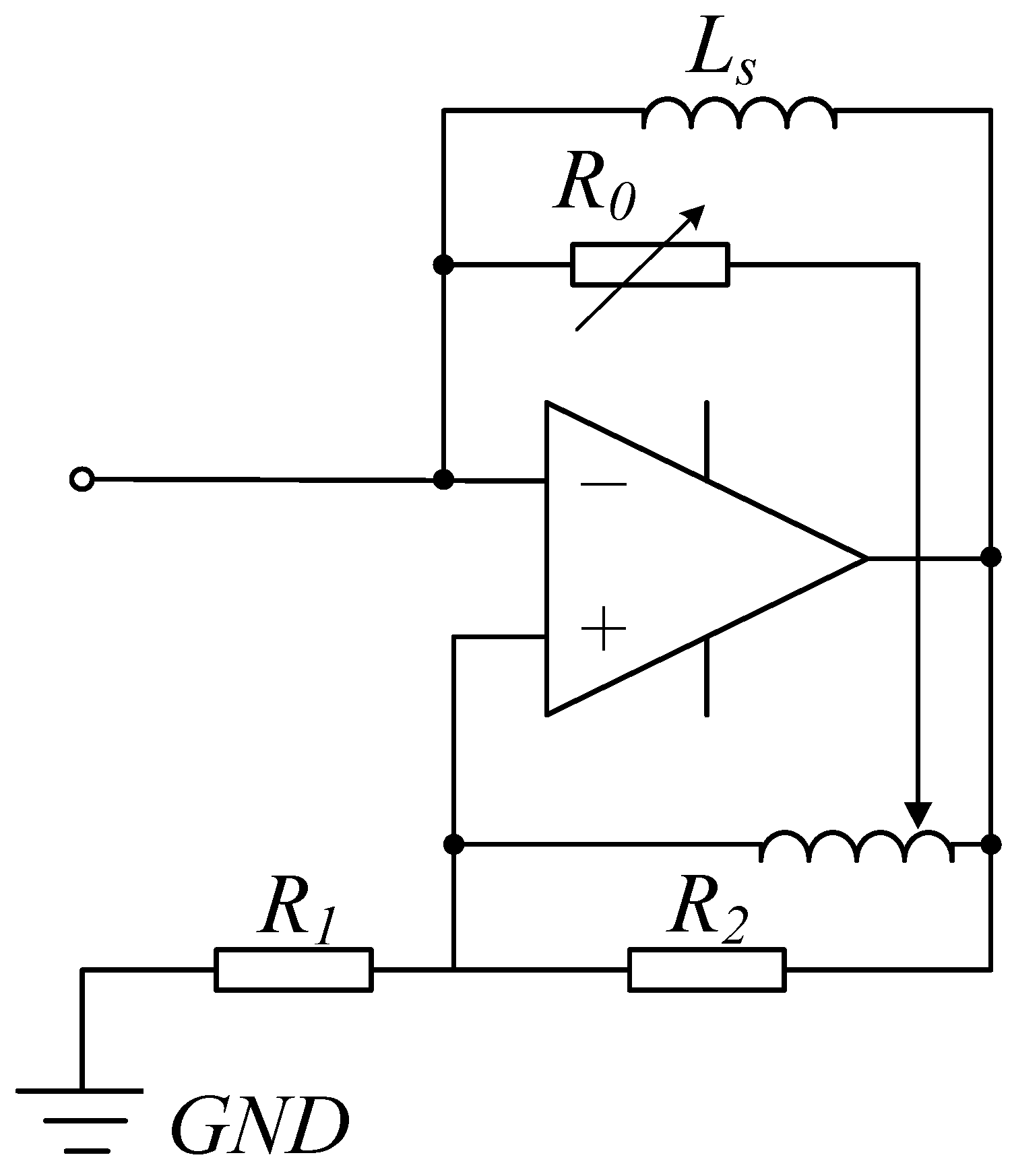
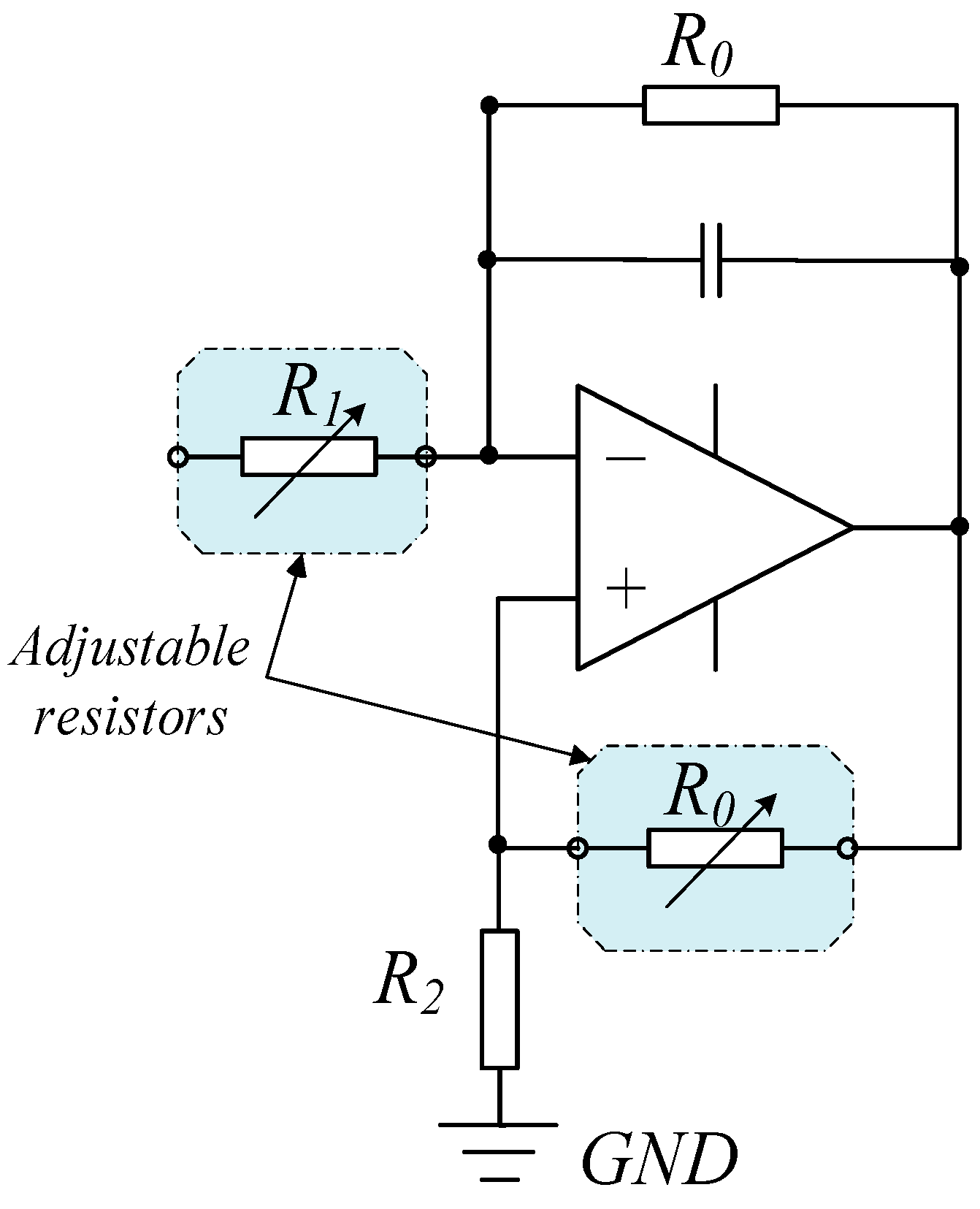
The vibration reduction performance of the negative capacitance shunt may become worse when a small discrepancy in capacitance of the external shunt and piezoelectric element exists. An example is temperature sensitivity. Based on this possible failure of the shunt, Sluka et al. [113] proposed a method for automatic stabilization and adjustment of the negative capacitance shunt by an additional feedback control. Figure 14 shows a negative capacitance with a feedback control [114]. The equivalent capacitance is
This equation can be approximated as , the real part can be adjusted by R1 and R2, . The imaginary part can be adjusted by R0, . The negative capacitor was controlled by R0 and R1.
The vibration isolation of the shunt shown in Figure 14 was effective over a narrow frequency. Kodejska et al. [126] proposed a broadband adaptive negative capacitance shunt circuit shown in Figure 15. The shunt circuit was built up based on NIC. Two resistors R0 and R1 constructed as a pair of a light-emitted diode and a photo-resistor were used to adjust the value of the negative capacitance. An iterative control algorithm was applied, and a range of 0.5–3 KHz vibration reduction was achieved.
In general, a resonant shunt is effective to reduce a target mode vibration, but it is very sensitive to the variation of the natural frequency and the inherent capacitance of the piezoelectric transducer. To use a resonant shunt and make it more adaptive, Gripp et al. [127] proposed an adaptive resonant piezoelectric vibration absorber enhanced by a negative capacitance. The resonant shunt circuit autonomously adapts its inductance value by comparing the phase difference of the vibration velocity and the current flowing through the shunt circuit. The negative capacitance was added to the resonant shunted piezoelectric absorber to improve the vibration control performance. The results showed that the vibration of the shell can be reduced by 5 dB despite the frequency varying from 191 Hz to 193 Hz.
The mechanical system becomes complicated with the development of technology. Generally, it may contain many structures, electronics, and a control system. The stiffness and electrical features of all these components are hard to obtain, which inevitably increase the difficulties of designing and optimization a shunt circuit. Then an adaptive shunt provides an effective way to overcome these uncertainties and thus to improve the vibration control performance of a mechatronic system.
7. Challenges in Shunt Damping Vibration Control
7.1. Noise and Acoustic Control
Noise and acoustic control from vibrating structures is a key point in various fields such as automobiles, airplanes, ships, submarines, and buildings. There have been many attempts to reduce or control the noise radiating from structures. Ahmadian and Jeric [128] applied the RLC resonant shunt to increase the acoustic transmission loss of a plate shown in Figure 16. A variable inductor was used to tune the frequency of the circuit and it was implemented based on the operational amplifier circuit. The experimental results showed that 7 dB increase of transmission loss can be achieved for a broad band input of 10–10,000 Hz. Kim and Lee [129] also used a resonant shunted piezoelectric transducer on panel structures to reduce the radiated noise. Fleming et al. [130] used the passive in-series resistor–capacitor shunt of an electrodynamic loudspeaker efficiently to realize a single resonant mode attenuation in a narrow frequency range. However, the resonant circuit is limited to the frequency and the absorbing bandwidth is narrow. Consequently, Kim et al. [131] employed a negative capacitance shunt circuit for broadband noise control of a piezoelectric smart panel. The acceleration levels at the fifth, ninth, 11th, and 21st modes were reduced by 15 dB, 7 dB, 4 dB, and 3 dB, respectively. The transmission loss was increased by 7–2 dB at 500–2000 Hz.
Mokry et al. [111] presented the general approach of noise and vibration control using piezoelectric materials and negative capacitance circuits. The results implied that the acoustic absorption coefficient of the sound absorption system can be controlled. The transmission loss can be reduced by 7 dB in the broad frequency range. This method is called active elasticity control (AEC). Fukada et al. [112] studied sound isolation also using a piezoelectric polymer film connected to a negative capacitance. The transmission loss can be reduced by 13 dB at frequencies around 1 kHz. Kadama et al. [132] studied the sound-induced vibration control using a piezoelectric composite sheet connected to a negative capacitance shunt. In order to overcome the discrepancy of the external and internal capacitance, Sluka et al. [114] proposed an adaptive negative capacitance shunted piezoelectric membrane to improve sound shielding efficiency. The shunt circuit can be found in Figure 14.
Lissek et al. [133] presented the theory unifying passive and active acoustic impedance control strategies, introducing the concept of electroacoustic absorbers. The equivalence between shunts and active control was formalized through the introduction of a one-degree-of-freedom acoustic resonator accounting for both electric shunts and acoustic feedbacks. Broadband acoustic performances have been obtained by using the resistance, negative resistance shunt and direct impedance control. Černík and Mokry [134] considered that the real and imaginary parts of the shunt circuit impedance must be negative in the considered system to obtain a perfect sound absorption in a broad frequency range. The results implied that it is possible to decrease the acoustic reflection coefficient at an arbitrary frequency by proper adjustment of the parameters of the negative resistance shunt. Zhang et al. [135] demonstrated effective broadband sound absorption by reducing the mechanical reactance of a loudspeaker using a negative inductance negative resistance shunt circuit through electro-mechanical coupling, which induces reactance with different signs from that of loudspeaker. The results implied that the sound absorption coefficient is well above 0.5 across frequencies between 150 and 1200 Hz. Tao et al. [136] also used the negative impedance converter to realize the sound absorption of a finite micro-perforated panel.
Because the influence of the noise and acoustic is up to several thousand hertz, the resonant shunt is limited for such a large range bandwidth. If a piezoelectric and an electromagnetic transducer are employed, the negative impedance shunt may provide a feasible method to reduce the transmission loss. For an electromagnetic transducer, the influence from the inductance increases dramatically when the frequency is up to kilohertz. In this case, the influence from the resistance is very small. Then the negative inductance shunt can be used to control high frequency noise. Therefore, the negative impedance and adaptive negative impedance shunts have great potential in noise and acoustic control engineering.
7.2. Dual-Functional Energy Harvesting and Shunt Damping
In principle, shunt damping vibration control technology uses a smart transducer and a shunt circuit to realize vibration control performance. Smart transducers can transform the kinetic or vibrational energy into electricity, and the shunts (passive and active) regulate the electrical signal to obtain a considerable vibration attenuation performance. In view of energy conservation, this transformed electricity can be harvested [137]. Consequently, shunt damping technology is dual-functional as vibration control and energy harvesting [138]. Similarly, the dual-functional feature discussion of the shunt damping method can also be classified into passive and active.
As to the traditional passive shunts, the RC and RL circuit can be used to construct a two-order resonant circuit to harvest vibration energy [139]. On the other hand, this kind of circuit is a single mode shunt for control of structural vibration. Wilhelm et al. [140] presented a multimode vibration control by using the controlled harvesting and storage of vibration energy as electrical charge. The stored energy can then be recycled enabling the system to achieve a vibration reduction superior to that of a traditional semi-active system and approaching that of a fully active system. An array of one or more pre-charged capacitors is employed to provide a selection of various voltages, which may be selected to approximate a desired control signal. The capacitors can apply a control voltage to the piezoelectric actuators and can also collect current generated by the actuators as the structure strains in vibration. Zhu et al. [141] discussed the vibration damping and energy harvesting of linear motion electromagnetic devices. Harne et al. [142] utilized a piezoelectric film spring and a distributed mass layer suitable for the attenuation of surface vibrations and to convert a portion of the absorbed energy into electric power. Zuo and Cui [143] investigated dual-functional energy-harvesting and robust vibration control by integrating tuned mass damper and electromagnetic shunted resonant damping.
The mechanical energy transferred from the vibration source to the control system, and the electrical energy flowed from the smart transducer to the active shunt circuit. For the active shunt, there are two kinds of energy flowing and exchanging: the transformed energy from mechanical vibrations and that provided by the external source. Vaclavik at al. [144] designed an experimental system to determine the energy flows in the negative capacitance shunt. The result showed that the amplitudes of the electrical power were almost 100 times higher than the amplitudes of the input mechanical power. It was pointed out that such a high value of input mechanical and electrical power was caused by: (1) a relatively low electromechanical factor of the piezoelectric transducer, (2) the capacitance nature of the piezoelectric transducer, and (3) wall-plug efficiency. After that, Vaclavik et al. [145] established an experiment to analyze wall-plug efficiency by using linear and switching synthetic negative capacitance. The results demonstrated that more that 85% of electrical power was dissipated on the transistors of the linear amplifier. The switching amplifier can reduce the input electrical power by more than 90%, but it made the circuit complicated. The energy flowing discussion on active shunts can help researchers design energy-saving devices and make the active shunt more suitable for industrial applications.
Finally, the investigation of energy harvesting of the piezoelectric and electromagnetic transducers and their vibration control effect have great potentials for future study. Furthermore, one should also pay attention to self-powered shunt damping by using energy harvesting technology [137,146,147,148,149].
8. Conclusions
Shunt damping technology has been widely studied and it has shown a good potential in vibration control engineering. The major efforts and findings of the recent literature in the field have been focused mainly on piezoelectric shunt damping and electromagnetic shunt damping. When designing the shunt circuit, the electrical feature of the electrical loop changes and this can produce vibration control effectiveness of the mechanical structure. We summarized shunt damping control by combing PSD and EMSD together to obtain some common characteristics of passive and active shunts. A common control principle and the analytical framework of the shunt circuit were established and provide a feasible way to deal with the coupled PSD and EMSD problem.
As the environment becomes more complicated, the traditional passive and active shunts may not meet the requirements of a system. Consequently, the adaptive shunt may have a great potential in future research. The adaptive negative resistance shunt can be used to change the stiffness of an electromagnetic transducer, therefore it is worthy of further discussions for the variable stiffness structures and absorption application. To date, research on PSD and EMSD has been carried out in depth. Few literature references have been concerned with shunted magnetostrictive transducers. Hence, extending shunt damping technology into other smart structures and investigating the corresponding characteristics is also worthy of discussion.
Furthermore, a series of design and optimization methods have been developed to establish the relationship between the electrical and mechanical impedance of passive shunts. If a system is equivalent to an impedance, such as mechanical impedance, electrical impedance, and air and liquid impedance, etc. by matching the impedances to a magneto-mechanic transducer, vibrations can be reduced [150]. This technology may provide a novel method for structural vibration control engineering. After years of research, structural vibration control using shunt damping technology has been thoroughly developed. Active shunts can provide a suitable choice for reducing broadband noise response. The combination of energy harvesting technology and vibration control of a shunt circuit, development of the corresponding theory, optimization and experimental method, and discussion of the dual-functional characteristics of shunt damping technology may be future hotspots of this field.
Acknowledgments
This work is national natural science foundation of China under grant Nos. 11602223 and 51675488, State Key Laboratory for Strength and Vibration of Mechanical Structures, Xi’an Jiaotong University under grant Nos. SV2016-KF-14 and SV2016-KF-07, Key Laboratory of Space Utilization, Chinese Academy of Sciences under grant No. LSU-2016-01-01, and Science Foundation of Zhejiang Sci-Tech University (ZSTU) under grant No. 16022060-Y.
Author Contributions
Bo Yan and Zifan Hu wrote the manuscript; Ke Wang organized the passive shunt circuit section; Chuanyu Wu concluded the active shunts section; Xinong Zhang, Bo Yan provided the figures of the manuscript.
Conflicts of Interest
The authors declare no conflict of interest.
References
- Jiang, Z.; Christenson, R.E. A fully dynamic magneto-rheological fluid damper model. Smart Mater. Struct. 2012, 21, 065002. [Google Scholar] [CrossRef]
- Song, G.; Sethi, V.; Li, H.N. Vibration control of civil structures using piezoceramic smart materials: A review. Eng. Struct. 2006, 28, 1513–1524. [Google Scholar] [CrossRef]
- Vautier, B.J.G.; Moheimani, S.O.R. Vibration reduction of resonant structures using charge controlled piezoelectric actuators. Electron. Lett. 2003, 39, 1036–1038. [Google Scholar] [CrossRef]
- Moheimani, S.O.R.; Vautier, B.J.G. Resonant control of structural vibration using charge-driven piezoelectric actuators. IEEE Trans. Control Syst. Technol. 2005, 13, 1021–1035. [Google Scholar] [CrossRef]
- Rodriguez-Fortun, J.M.; Orus, J.; Alfonso, J.; Gimeno, F.B.; Jose, A.; Castellanos, J.A. Flatness-Based Active Vibration Control for Piezoelectric Actuators. IEEE/ASME Trans. Mech. 2013, 18, 221–229. [Google Scholar] [CrossRef]
- Damanpack, A.R.; Bodaghi, M.; Aghdam, M.M.; Shakeri, M. On the vibration control capability of shape memory alloy composite beams. Compos. Struct. 2014, 110, 325–334. [Google Scholar] [CrossRef]
- Song, G.; Ma, N.; Li, H.-N. Applications of shape memory alloys in civil structures. Eng. Struct. 2006, 28, 1266–1274. [Google Scholar] [CrossRef]
- Ebrahimi, B.; Khamesee, M.B.; Golnaraghi, F. Eddy current damper feasibility in automobile suspension: Modeling, simulation and testing. Smart Mater. Struct. 2009, 18, 015017. [Google Scholar] [CrossRef]
- Chen, J.Y.; Zhou, J.B.; Meng, G.; Zhang, W.M. Evaluation of Eddy-Current Effects on Diamagnetic Bearings for Microsystems. IEEE Trans. Ind. Electron. 2009, 56, 964–972. [Google Scholar] [CrossRef]
- Beek, T.V.; Pluk, K.; Jansen, H.; Lomonova, E. Optimisation and measurement of eddy current damping in a passive tuned mass damper. IET Electr. Power Appl. 2016, 10, 641–648. [Google Scholar] [CrossRef]
- Bae, J.-S.; Kwak, M.K.; Inman, D.J. Vibration suppression of a cantilever beam using eddy current damper. J. Sound Vib. 2005, 284, 805–824. [Google Scholar] [CrossRef]
- Balas, M.J. Direct velocity feedback control of large space structures. J. Guid. Control Dynam. 1979, 2, 252–253. [Google Scholar] [CrossRef]
- Lieh, J. Semiactive and Active Suspensions for Vehicle Ride Control Using Velocity Feedback. J. Vib. Control 1997, 3, 201–212. [Google Scholar] [CrossRef]
- Ǻström, K.J.; Hägglund, T. PID Controllers: Theory, Design, and Tuning; Instrument Society of America: Research Triangle Park, NC, USA, 1995. [Google Scholar]
- Khot, S.; Yelve, N.P.; Tomar, R.; Desai, S.; Vittal, S. Active vibration control of cantilever beam by using PID based output feedback controller. J. Vib. Control 2012, 18, 366–372. [Google Scholar] [CrossRef]
- Snyder, S.D.; Tanaka, N. On feedforward active control of sound and vibration using vibration error signals. J. Acoust. Soc. Am. 1993, 94, 2181–2193. [Google Scholar] [CrossRef]
- Su, T.; Ishida, M.; Hori, T. Suppression control method for torque vibration of three-phase HB-type stepping motor utilizing feedforward control. IEEE Trans. Ind. Electron. 2002, 49, 896–904. [Google Scholar] [CrossRef]
- Alma, M.; Martinez, J.J.; Landau, I.D.; Buche, G. Design and Tuning of Reduced Order H-Infinity Feedforward Compensators for Active Vibration Control. IEEE Trans. Control Syst. Technol. 2012, 20, 554–561. [Google Scholar] [CrossRef]
- Peng, F.; Ng, A.; Hu, Y.-R. Actuator placement optimization and adaptive vibration control of plate smart structures. J. Intell. Mater. Syst. Struct. 2005, 16, 263–271. [Google Scholar] [CrossRef]
- Ma, K.; Ghasemi-Nejhad, M.N. Adaptive Control of Flexible Active Composite Manipulators Driven by Piezoelectric Patches and Active Struts With Dead Zones. IEEE Trans. Control Syst. Technol. 2008, 16, 897–907. [Google Scholar]
- Kwak, M.; Sciulli, D. Fuzzy-logic based vibration suppression control experiments on active structures. J. Sound Vib. 1996, 191, 15–28. [Google Scholar] [CrossRef]
- Han, J.-H.; Lee, I. Optimal placement of piezoelectric sensors and actuators for vibration control of a composite plate using genetic algorithms. Smart Mater. Struct. 1999, 8, 257. [Google Scholar] [CrossRef]
- Sun, J.; Poo, A.N.; Chew, C.M.; Ang, M.H.; Hong, G.S. Optimization of Mechatronic Design Quotient Using Genetic Algorithm in Vibration Controllers for Flexible Beams. J. Vib. Control 2009, 15, 1603–1626. [Google Scholar] [CrossRef]
- Itoh, K.; Iwasaki, M.; Matsui, N. Optimal design of robust vibration suppression controller using genetic algorithms. IEEE Trans. Ind. Electron. 2004, 51, 947–953. [Google Scholar] [CrossRef]
- Madkour, A.; Hossain, M.A.; Dahal, K.P.; Yu, H. Intelligent Learning Algorithms for Active Vibration Control. IEEE Trans. Syst. Man Cybern. C (Appl. Rev.) 2007, 37, 1022–1033. [Google Scholar] [CrossRef]
- Viana, F.A.C.; Kotinda, G.I.; Rade, D.A.; Steffen, V., Jr. Tuning dynamic vibration absorbers by using ant colony optimization. Comput. Struct. 2008, 86, 1539–1549. [Google Scholar] [CrossRef]
- Forward, R.L. Electronic damping of vibrations in optical structures. Appl. Opt. 1979, 18, 690–697. [Google Scholar] [CrossRef] [PubMed]
- Hollkamp, J.J. Multimodal passive vibration suppression with piezoelectric materials and resonant shunts. J. Intell. Mater. Syst. Struct. 1994, 5, 49–57. [Google Scholar] [CrossRef]
- Hagood, N.W.; von Flotow, A. Damping of structural vibrations with piezoelectric materials and passive electrical networks. J. Sound Vib. 1991, 146, 243–268. [Google Scholar] [CrossRef]
- Behrens, S.; Fleming, A.J.; Moheimani, S.O.R. Passive vibration control via electromagnetic shunt damping. IEEE/ASME Trans. Mech. 2005, 10, 118–122. [Google Scholar] [CrossRef]
- Behrens, S.; Fleming, A.J.; Moheimani, S.O.R. Ieee Electromagnetic shunt damping. In Proceedings of the 2003 IEEE/ASME International Conference on Advanced Intelligent Mechatronics (Aim 2003), Kobe, Japan, 20–24 July 2003; Volumes 1 and 2, pp. 1145–1150. [Google Scholar]
- Hollkamp, J.J.; Starchville, T.F. A self-tuning piezoelectric vibration absorber. J. Intell. Mater. Syst. Struct. 1994, 5, 559–566. [Google Scholar] [CrossRef]
- Moheimani, S.O.R. A survey of recent innovations in vibration damping and control using shunted piezoelectric transducers. IEEE Trans. Control Syst. Technol. 2003, 11, 482–494. [Google Scholar] [CrossRef]
- Cheng, T.H.; Oh, I.K. A current-flowing electromagnetic shunt damper for multi-mode vibration control of cantilever beams. Smart Mater. Struct. 2009, 18, 095036. [Google Scholar] [CrossRef]
- Fleming, A.J.; Behrens, S.; Moheimani, S.O.R. Synthetic impedance for implementation of piezoelectric shunt-damping circuits. Electron. Lett. 2000, 36, 1525–1526. [Google Scholar] [CrossRef]
- Fleming, A.; Moheimani, S. Adaptive piezoelectric shunt damping. Smart Mater. Struct. 2003, 12, 36–48. [Google Scholar] [CrossRef]
- De Marneffe, B.; Preumont, A. Vibration damping with negative capacitance shunts: Theory and experiment. Smart Mater. Struct. 2008, 17, 035015. [Google Scholar] [CrossRef]
- Ji, H.L.; Qiu, J.H.; Cheng, J.; Inman, D. Application of a negative capacitance circuit in synchronized switch damping techniques for vibration suppression. J. Vib. Acoust. 2011, 133, 041015. [Google Scholar] [CrossRef]
- Fukada, E.; Date, M.; Sekigawa, K. Vibration Control by Magnetostrictive Actuator Coupled with Negative Inductance Circuits. Jpn. J. Appl. Phys. 2003, 42, 7124. [Google Scholar] [CrossRef]
- Scheidler, J.J.; Asnani, V.M.; Dapino, M.J. Design and testing of a dynamically-tuned magnetostrictive spring with electrically controlled stiffness. In Proceedings of the SPIE 9433, Industrial and Commercial Applications of Smart Structures Technologies, San Diego, CA, USA, 8 March 2015. [Google Scholar]
- Scheidler, J.J.; Asnani, V.M.; Dapino, M.J. Dynamically tuned magnetostrictive spring with electrically controlled stiffness. Smart Mater. Struct. 2016, 25, 035007. [Google Scholar] [CrossRef]
- Adriaens, H.J.; De Koning, W.L.; Banning, R. Modeling piezoelectric actuators. IEEE/ASME Trans. Mech. 2000, 5, 331–341. [Google Scholar] [CrossRef]
- Fuller, C.; Elliott, S.J.; Nelson, P.R. Active Vibration Control. In Handbook of Noise and Vibration Control; Acadamic Press: San Diego, CA, USA, 1996; pp. 770–784. [Google Scholar]
- Gandhi, M.V.; Thompson, B. Smart Materials and Structures; Chapman &Hall: London, UK, 1992. [Google Scholar]
- Fleming, A.J. Synthesis and Implementation of Sensor-Less Shunt Controllers for Piezoelectric and Electromagnetic Vibration Control; The University of Newcastle: Callaghan, Australia, 2004. [Google Scholar]
- Dosch, J.J.; Inman, D.J.; Garcia, E. A self-sensing piezoelectric actuator for collocated control. J. Intell. Mater. Syst. Struct. 1992, 3, 166–185. [Google Scholar] [CrossRef]
- Giovanni, C. A critical analysis of electric shunt circuits employed in piezoelectric passive vibration damping. Smart Mater. Struct. 2001, 10, 1059. [Google Scholar]
- Sodano, H.A.; Bae, J.-S.; Inman, D.J.; Keith Belvin, W. Concept and model of eddy current damper for vibration suppression of a beam. J. Sound Vib. 2005, 288, 1177–1196. [Google Scholar] [CrossRef]
- Ebrahimi, B.; Khamesee, M.B.; Golnaraghi, M.F. Design and modeling of a magnetic shock absorber based on eddy current damping effect. J. Sound Vib. 2008, 315, 875–889. [Google Scholar] [CrossRef]
- Zuo, L.; Chen, X.; Nayfeh, S. Design and analysis of a new type of electromagnetic damper with increased energy density. J. Vib. Acoust. 2011, 133, 041006. [Google Scholar] [CrossRef]
- Furlani, E.P. Permanent Magnet and Electromechanical Devices; Mayergoyz, I., Ed.; Acdemic Press: New York, NY, USA, 2001. [Google Scholar]
- Niu, H.P.; Zhang, X.N.; Xie, S.L.; Wang, P.P. A new electromagnetic shunt damping treatment and vibration control of beam structures. Smart Mater. Struct. 2009, 18, 045009. [Google Scholar] [CrossRef]
- Yan, B.; Zhang, X.N.; Niu, H.P. Design and test of a novel isolator with negative resistance electromagnetic shunt damping. Smart Mater. Struct. 2012, 21, 035003. [Google Scholar] [CrossRef]
- Niederberger, D.; Behrens, S.; Fleming, A.J.; Moheimani, S.O.R.; Morari, M. Adaptive electromagnetic shunt damping. IEEE/ASME Trans. Mech. 2006, 11, 103–108. [Google Scholar] [CrossRef]
- Yan, B.; Zhang, X.N.; Niu, H.P. Vibration isolation of a beam via negative resistance electromagnetic shunt dampers. J. Intell. Mater. Syst. Struct. 2012, 23, 665–673. [Google Scholar] [CrossRef]
- Zhang, X.N.; Niu, H.P.; Yan, B. A novel multimode negative inductance negative resistance shunted electromagnetic damping and its application on a cantilever plate. J. Sound Vib. 2012, 331, 2257–2271. [Google Scholar] [CrossRef]
- Sodano, H.A.; Bae, J.S.; Inman, D.J.; Belvin, W.K. Improved concept and model of eddy current damper. J. Vib. Acoust. 2006, 128, 294–302. [Google Scholar] [CrossRef]
- Ebrahimi, B.; Khamesee, M.B.; Golnaraghi, F. Permanent magnet configuration in design of an eddy current damper. Microsyst. Technol. 2010, 16, 19–24. [Google Scholar] [CrossRef]
- Zuo, L.; Scully, B.; Shestani, J.; Zhou, Y. Design and characterization of an electromagnetic energy harvester for vehicle suspensions. Smart Mater. Struct. 2010, 19, 045003. [Google Scholar] [CrossRef]
- Yan, B.; Zhang, X.; Luo, Y.; Zhang, Z.; Xie, S.; Zhang, Y. Negative impedance shunted electromagnetic absorber for broadband absorbing: Experimental investigation. Smart Mater. Struct. 2014, 23, 125044. [Google Scholar] [CrossRef]
- Yan, B.; Luo, Y.; Zhang, X. Structural multimode vibration absorbing with electromagnetic shunt damping. J. Vib. Control 2016, 22, 1604–1617. [Google Scholar] [CrossRef]
- Harris, C.M.; Piersol, A.G. Harris’ Shock and Vibration Handbook; McGraw-Hill: New York, NY, USA, 2002. [Google Scholar]
- Meirovitch, L. Fundamentals of Vibrations; Waveland Press: Long Grove, IL, USA, 2010. [Google Scholar]
- Den Hartog, J.P. Mechanical Vibrations; Courier Corporation: North Chelmsford, MA, USA, 1985. [Google Scholar]
- Neubauer, M.; Oleskiewicz, R.; Popp, K.; Krzyzynski, T. Optimization of damping and absorbing performance of shunted piezo elements utilizing negative capacitance. J. Sound Vib. 2006, 298, 84–107. [Google Scholar] [CrossRef]
- Kim, J.-S.; Jeong, U.-C.; Seo, J.-H.; Kim, Y.-D.; Lee, O.-D.; Oh, J.-E. Structure borne noise control of a clamped panel using shunt damping system. Sens. Actuators A Phys. 2015, 233, 330–348. [Google Scholar] [CrossRef]
- Kandagal, S.B. KartikVenkatraman Structural vibration control using resistively shunted piezoceramics. Struct. Eng. Mech. 2002, 14, 521–542. [Google Scholar] [CrossRef]
- Jaehwan, K.; Yeon-Ho, R.; Seung-Bok, C. New shunting parameter tuning method for piezoelectric damping based on measured electrical impedance. Smart Mater. Struct. 2000, 9, 868. [Google Scholar]
- Inoue, T.; Ishida, Y.; Sumi, M. Vibration suppression using electromagnetic resonant shunt damper. J. Vib. Acoust. 2008, 130, 041003. [Google Scholar] [CrossRef]
- Kozlowski, M.V.; Cole, D.G.; Clark, R.L. A comprehensive study of the RL series resonant shunted piezoelectric: A feedback controls perspective. J. Vib. Acoust. 2011, 133, 011012. [Google Scholar] [CrossRef]
- Soltani, P.; Kerschen, G.; Tondreau, G.; Deraemaeker, A. Piezoelectric vibration damping using resonant shunt circuits: An exact solution. Smart Mater. Struct. 2014, 23, 125014. [Google Scholar] [CrossRef]
- Lim, S.C.; Choi, S.B. Vibration control of an HDD disk-spindle system utilizing piezoelectric bimorph shunt damping: I. Dynamic analysis and modeling of the shunted drive. Smart Mater. Struct. 2007, 16, 891–900. [Google Scholar] [CrossRef]
- Lim, S.C.; Choi, S.B. Vibration control of an HDD disk-spindle system using piezoelectric bimorph shunt damping: II. Optimal design and shunt damping implementation. Smart Mater. Struct. 2007, 16, 901–908. [Google Scholar] [CrossRef]
- Schoeftner, J.; Irschik, H. Passive damping and exact annihilation of vibrations of beams using shaped piezoelectric layers and tuned inductive networks. Smart Mater. Struct. 2009, 18, 125008. [Google Scholar] [CrossRef]
- Wu, S.-Y. Piezoelectric shunts with a parallel R-L circuit for structural damping and vibration control. In Proceedings of the SPIE 2720, Smart Structures and Materials 1996: Passive Damping and Isolation, San Diego, CA, USA, 25 February 1996. [Google Scholar]
- Park, C.H. Dynamics modelling of beams with shunted piezoelectric elements. J. Sound Vib. 2003, 268, 115–129. [Google Scholar] [CrossRef]
- Nguyen, C.H.; Pietrzko, S.J. FE analysis of a PZT-actuated adaptive beam with vibration damping using a parallel R–L shunt circuit. Finite Elem. Anal. Des. 2006, 42, 1231–1239. [Google Scholar] [CrossRef]
- Li, N. Virtual piezoelectric vibration absorber with LR parallel shunt circuit. In Advanced Mechanical Design; Trans Tech Publications: Zurich, Switzerland, 2012; pp. 1165–1168. [Google Scholar]
- Guo, K.; Jiang, J. Independent modal resonant shunt for multimode vibration control of a truss-cored sandwich panel. Int. J. Dyn. Control 2014, 2, 326–334. [Google Scholar] [CrossRef]
- Sun, H.; Yang, Z.; Li, K.; Li, B.; Xie, J.; Wu, D.; Zhang, L. Vibration suppression of a hard disk driver actuator arm using piezoelectric shunt damping with a topology-optimized PZT transducer. Smart Mater. Struct. 2009, 18, 065010. [Google Scholar] [CrossRef]
- Yamada, K.; Matsuhisa, H.; Utsuno, H.; Sawada, K. Optimum tuning of series and parallel LR circuits for passive vibration suppression using piezoelectric elements. J. Sound Vib. 2010, 329, 5036–5057. [Google Scholar] [CrossRef]
- Høgsberg, J.; Krenk, S. Balanced calibration of resonant shunt circuits for piezoelectric vibration control. J. Intell. Mater. Syst. Struct. 2012, 23, 1937–1948. [Google Scholar] [CrossRef]
- Krenk, S.; Høgsberg, J.B. A Family of Resonant Vibration Control Formats. In Proceedings of the 5th European Conference on Structural Control, Genoa, Italy, 18–20 June 2012. [Google Scholar]
- Krenk, S.; Høgsberg, J. Optimal resonant control of flexible structures. J. Sound Vib. 2009, 323, 530–554. [Google Scholar] [CrossRef]
- Krenk, S.; Hogsberg, J. Equal modal damping design for a family of resonant vibration control formats. J. Vib. Control 2013, 19, 1294–1315. [Google Scholar] [CrossRef]
- Høgsberg, J.; Krenk, S. Calibration of piezoelectric RL shunts with explicit residual mode correction. J. Sound Vib. 2017, 386, 65–81. [Google Scholar] [CrossRef]
- Wu, S.-Y. Method for multiple mode piezoelectric shunting with single PZT transducer for vibration control. J. Intell. Mater. Syst. Struct. 1998, 9, 991–998. [Google Scholar] [CrossRef]
- Wu, S.-Y. Method for multiple-mode shunt damping of structural vibration using a single PZT transducer. In Proceedings of the 5th Annual International Symposium on Smart Structures and Materials, San Diego, CA, USA, 1–5 March 1998. [Google Scholar]
- Behrens, S.; Moheimani, S.R. Current flowing multiple-mode piezoelectric shunt dampener. In Proceedings of the SPIE’s 9th Annual International Symposium on Smart Structures and Materials, San Diego, CA, USA, 17–21 March 2002. [Google Scholar]
- Behrens, S.; Moheimani, S.R.; Fleming, A. Multiple mode current flowing passive piezoelectric shunt controller. J. Sound Vib. 2003, 266, 929–942. [Google Scholar] [CrossRef]
- Fleming, A.J.; Moheimani, S.O.R. Improved current and charge amplifiers for driving piezoelectric loads, and issues in signal processing design for synthesis of shunt damping circuits. J. Intell. Mater. Syst. Struct. 2004, 15, 77–92. [Google Scholar] [CrossRef]
- Fleming, A.J.; Behrens, S.; Moheimani, S.O.R. Reducing the inductance requirements of piezoelectric shunt damping systems. Smart Mater. Struct. 2003, 12, 57–64. [Google Scholar] [CrossRef]
- Vasques, C.M.A. Improved passive shunt vibration control of smart piezo-elastic beams using modal piezoelectric transducers with shaped electrodes. Smart Mater. Struct. 2012, 21, 125003. [Google Scholar] [CrossRef]
- Fleming, A.J.; Behrens, S.; Moheimani, S.O.R. IEEE Active LQR and H2 shunt control of electromagnetic transducers. In Proceedings of the 42nd IEEE Conference on Decision and Control, Maui, HI, USA, 9–12 December 2003; pp. 2294–2299. [Google Scholar]
- Fleming, A.J.; Moheimani, S.R. Control orientated synthesis of high-performance piezoelectric shunt impedances for structural vibration control. IEEE Trans. Control Syst. Technol. 2005, 13, 98–112. [Google Scholar] [CrossRef]
- Wu, S.-Y. Broadband piezoelectric shunts for passive structural vibration control. In Proceedings of the SPIE’s 8th Annual International Symposium on Smart Structures and Materials, Newport Beach, CA, USA, 4 March 2001. [Google Scholar]
- Merrill, J. Theory of the negative impedance converter. Bell Syst. Tech. J. 1951, 30, 88–109. [Google Scholar] [CrossRef]
- Behrens, S.; Fleming, A.J.; Moheimani, S.O.R. A broadband controller for shunt piezoelectric damping of structural vibration. Smart Mater. Struct. 2003, 12, 18–28. [Google Scholar] [CrossRef]
- Park, C.H.; Park, H.C. Multiple-Mode Structural Vibration Control Using Negative Capacitive Shunt Damping. J. Mech. Sci. Technol. 2003, 17, 1650–1658. [Google Scholar] [CrossRef]
- Manzoni, S.; Moschini, S.; Redaelli, M.; Vanali, M. Vibration attenuation by means of piezoelectric transducer shunted to synthetic negative capacitance. J. Sound Vib. 2012, 331, 4644–4657. [Google Scholar] [CrossRef]
- Mokrani, B.; Rodrigues, G.; Ioan, B.; Bastaits, R.; Preumont, A. Synchronized switch damping on inductor and negative capacitance. J. Intell. Mater. Syst. Struct. 2012, 23, 2065–2075. [Google Scholar] [CrossRef]
- Beck, B.S.; Cunefare, K.A.; Collet, M. The power output and efficiency of a negative capacitance shunt for vibration control of a flexural system. Smart Mater. Struct. 2013, 22, 065009. [Google Scholar] [CrossRef]
- Qureshi, E.M.; Shen, X.; Chang, L. Power output and efficiency of a negative capacitance and inductance shunt for structural vibration control under broadband excitation. Int. J. Aeronaut. Space Sci. 2015, 16, 223–246. [Google Scholar] [CrossRef]
- Salloum, R.; Heuss, O.; Götz, B.; Mayer, D. Optimally tuned resonant negative capacitance for piezoelectric shunt damping based on measured electromechanical impedance. In Proceedings of the SPIE 9433, Industrial and Commercial Applications of Smart Structures Technologies 2015, San Diego, CA, USA, 8 March 2015. [Google Scholar]
- Necasek, J.; Vaclavik, J.; Marton, P. Digital synthetic impedance for application in vibration damping. Rev. Sci. Instrum. 2016, 87, 024704. [Google Scholar] [CrossRef] [PubMed]
- Alessandro, S.; Guglielmo, S.A.; Guy, R.; Geert, S. A 2-collinear-DoF strut with embedded negative-resistance electromagnetic shunt dampers for spacecraft micro-vibration. Smart Mater. Struct. 2017, 26, 045031. [Google Scholar]
- McDaid, A.J.; Mace, B.R. A self-tuning electromagnetic vibration absorber with adaptive shunt electronics. Smart Mater. Struct. 2013, 22, 105013. [Google Scholar] [CrossRef]
- Yan, B.; Zhang, X.; Luo, Y. Investigation of negative resistance shunt damping for the vibration control of a plate. Int. J. Appl. Electrom. 2014, 45, 93–100. [Google Scholar]
- Date, M.; Kutani, M.; Sakai, S. Electrically controlled elasticity utilizing piezoelectric coupling. J. Appl. Phys. 1999, 87, 863–868. [Google Scholar] [CrossRef]
- Mokrý, P.; Fukada, E.; Yamamoto, K. Noise shielding system utilizing a thin piezoelectric membrane and elasticity control. J. Appl. Phys. 2003, 94, 789–796. [Google Scholar] [CrossRef]
- Mokrý, P.; Fukada, E.; Yamamoto, K. Sound absorbing system as an application of the active elasticity control technique. J. Appl. Phys. 2003, 94, 7356–7362. [Google Scholar] [CrossRef]
- Fukada, E.; Date, M.; Kimura, K.; Okubo, T.; Kodama, H.; Mokry, P.; Yamamoto, K. Sound isolation by piezoelectric polymer films connected to negative capacitance circuits. IEEE. Trans. Dielectr. Electr. Insul. 2004, 11, 328–333. [Google Scholar] [CrossRef]
- Sluka, T.; Mokry, P. Feedback control of piezoelectric actuator elastic properties in a vibration isolation system. Ferroelectrics 2007, 351, 51–61. [Google Scholar] [CrossRef]
- Sluka, T.; Kodama, H.; Fukada, E.; Mory, P. Sound shielding by a piezoelectric membrane and a negative capacitor with feedback control. IEEE Trans. Ultrason. Ferroelectr. Freq. Control 2008, 55, 1859–1866. [Google Scholar] [CrossRef] [PubMed]
- Steiger, K.; Mokrý, P. Finite element analysis of the macro fiber composite actuator: Macroscopic elastic and piezoelectric properties and active control thereof by means of negative capacitance shunt circuit. Smart Mater. Struct. 2015, 24, 025026. [Google Scholar] [CrossRef]
- Davis, C.L.; Lesieutre, G.A.; Dosch, J.J. Tunable electrically shunted piezoceramic vibration absorber. In Proceedings of the SPIE 3045, Smart Structures and Materials 1997: Passive Damping and Isolation, San Diego, CA, USA, 3 March 1997. [Google Scholar]
- Cunefare, K.A.; De Rosa, S.; Sadegh, N.; Larson, G. State-switched absorber for semi-active structural control. J. Intell. Mater. Syst. Struct. 2000, 11, 300–310. [Google Scholar] [CrossRef]
- Clark, W.W. Vibration control with state-switched piezoelectric materials. J. Intell. Mater. Syst. Struct. 2000, 11, 263–271. [Google Scholar] [CrossRef]
- Corr, L.R.; Clark, W.W. A novel semi-active multi-modal vibration control law for a piezoceramic actuator. J. Vib. Acoust. 2003, 125, 214–222. [Google Scholar] [CrossRef]
- Qureshi, E.M.; Shen, X.; Chen, J. Vibration control laws via shunted piezoelectric transducers: A review. Int. J. Aeronaut. Space Sci. 2014, 15, 1–19. [Google Scholar] [CrossRef]
- Christopher Robert, K.; Jeffrey, K. Adaptive Synchronized Switch Damping on an Inductor: A Self-Tuning Switching Law. Smart Mater. Struct. 2016. acceped. [Google Scholar]
- Han, X.; Neubauer, M.; Wallaschek, J. Improved piezoelectric switch shunt damping technique using negative capacitance. J. Sound Vib. 2013, 332, 7–16. [Google Scholar] [CrossRef]
- Niederberger, D.; Morari, M.; Pietrzko, S.J. Adaptive resonant shunted piezoelectric devices for vibration suppression. In Proceedings of the SPIE 5056, Smart Structures and Materials 2003: Smart Structures and Integrated Systems, San Diego, CA, USA, 5 August 2003. [Google Scholar]
- Niederberger, D.; Fleming, A.; Moheimani, S.R.; Morari, M. Adaptive multi-mode resonant piezoelectric shunt damping. Smart Mater. Struct. 2004, 13, 1025. [Google Scholar] [CrossRef]
- McDaid, A.J.; Mace, B.R. A Robust Adaptive Tuned Vibration Absorber Using Semi-Passive Shunt Electronics. IEEE Trans. Ind. Electron. 2016, 63, 5069–5077. [Google Scholar] [CrossRef]
- Kodejska, M.; Mokry, P.; Linhart, V.; Vaclavik, J.; Sluka, T. Adaptive Vibration Suppression System: An Iterative Control Law for a Piezoelectric Actuator Shunted by a Negative Capacitor. IEEE Trans. Ultrason. Ferroelectr. Freq. Control 2012, 59, 2785–2796. [Google Scholar] [CrossRef] [PubMed]
- Gripp, J.A.B.; Góes, L.C.S.; Heuss, O.; Scinocca, F. An adaptive piezoelectric vibration absorber enhanced by a negative capacitance applied to a shell structure. Smart Mater. Struct. 2015, 24, 125017. [Google Scholar] [CrossRef]
- Ahmadian, M.; Jeric, K.M. On the application of shunted piezoceramics for increasing acoustic transmission loss in structures. J. Sound Vib. 2001, 243, 347–359. [Google Scholar] [CrossRef]
- Kim, J.; Lee, J.-K. Broadband transmission noise reduction of smart panels featuring piezoelectric shunt circuits and sound-absorbing material. J. Acoust. Soc. Am. 2002, 112, 990–998. [Google Scholar] [CrossRef] [PubMed]
- Fleming, A.J.; Niederberger, D.; Moheimani, S.O.R.; Morari, M. Control of Resonant Acoustic Sound Fields by Electrical Shunting of a Loudspeaker. IEEE Trans. Control Syst. Techol. 2007, 15, 689–703. [Google Scholar] [CrossRef]
- Kim, J.; Jung, Y.-C. Broadband noise reduction of piezoelectric smart panel featuring negative-capacitive- converter shunt circuit. J. Acoust. Soc. Am. 2006, 120, 2017–2025. [Google Scholar] [CrossRef]
- Kodama, H.; Date, M.; Yamamoto, K.; Fukada, E. A study of sound shielding control of curved piezoelectric sheets connected to negative capacitance circuits. J. Sound Vib. 2008, 311, 898–911. [Google Scholar] [CrossRef]
- Lissek, H.; Boulandet, R.; Fleury, R. Electroacoustic absorbers: Bridging the gap between shunt loudspeakers and active sound absorption. J. Acoust. Soc. Am. 2011, 129, 2968–2978. [Google Scholar] [CrossRef] [PubMed]
- Černík, M.; Mokrý, P. Sound reflection in an acoustic impedance tube terminated with a loudspeaker shunted by a negative impedance converter. Smart Mater. Struct. 2012, 21, 115016. [Google Scholar] [CrossRef]
- Zhang, Y.; Chan, Y.-J.; Huang, L. Thin broadband noise absorption through acoustic reactance control by electro-mechanical coupling without sensor. J. Acoust. Soc. Am. 2014, 135, 2738–2745. [Google Scholar] [CrossRef] [PubMed]
- Tao, J.; Jing, R.; Qiu, X. Sound absorption of a finite micro-perforated panel backed by a shunted loudspeaker. J. Acoust. Soc. Am. 2014, 135, 231–238. [Google Scholar] [CrossRef] [PubMed]
- Shen, W.; Zhu, S.; Zhu, H.; Xu, Y.-L. Electromagnetic energy harvesting from structural vibrations during earthquakes. Smart Struct. Syst. 2016, 18, 449–470. [Google Scholar] [CrossRef]
- Lesieutre, G.A.; Ottman, G.K.; Hofmann, H.F. Damping as a result of piezoelectric energy harvesting. J. Sound Vib. 2004, 269, 991–1001. [Google Scholar] [CrossRef]
- Renno, J.M.; Daqaq, M.F.; Inman, D.J. On the optimal energy harvesting from a vibration source. J. Sound Vib. 2009, 320, 386–405. [Google Scholar] [CrossRef]
- Wilhelm, J.; Rajamani, R. Methods for Multimodal Vibration Suppression and Energy Harvesting Using Piezoelectric Actuators. J. Vib. Acoust. 2009, 131, 011001. [Google Scholar] [CrossRef]
- Zhu, S.; Shen, W.-A.; Xu, Y.-L. Linear electromagnetic devices for vibration damping and energy harvesting: Modeling and testing. Eng. Struct. 2012, 34, 198–212. [Google Scholar] [CrossRef]
- Harne, R.L. Development and testing of a dynamic absorber with corrugated piezoelectric spring for vibration control and energy harvesting applications. Mech. Syst. Signal Process. 2013, 36, 604–617. [Google Scholar] [CrossRef]
- Zuo, L.; Cui, W. Dual-Functional Energy-Harvesting and Vibration Control: Electromagnetic Resonant Shunt Series Tuned Mass Dampers. J. Vib. Acoust. 2013, 135, 051018. [Google Scholar] [CrossRef] [PubMed]
- Vaclavik, J.; Mokry, P. Measurement of mechanical and electrical energy flows in the semiactive piezoelectric shunt damping system. J. Intell. Mater. Syst. Struct. 2012, 23, 527–533. [Google Scholar] [CrossRef]
- Vaclavik, J.; Kodejska, M.; Mokry, P. Wall-plug efficiency analysis of semi-active piezoelectric shunt damping systems. J. Vib. Control 2016, 22, 2582–2590. [Google Scholar] [CrossRef]
- Ottman, G.K.; Hofmann, H.F.; Bhatt, A.C.; Lesieutre, G.A. Adaptive piezoelectric energy harvesting circuit for wireless remote power supply. IEEE Trans. Power Electron. 2002, 17, 669–676. [Google Scholar] [CrossRef]
- Rahimi, A.; Zorlu, O.; Muhtaroglu, A.; Kulah, H. Fully Self-Powered Electromagnetic Energy Harvesting System With Highly Efficient Dual Rail Output. IEEE Sens. J. 2012, 12, 2287–2298. [Google Scholar] [CrossRef]
- Zhang, S.; Yan, B.; Luo, Y.; Miao, W.; Xu, M. An Enhanced Piezoelectric Vibration Energy Harvesting System with Macro Fiber Composite. Shock Vib. 2015, 2015, 916870. [Google Scholar] [CrossRef]
- Yan, B.; Zhang, S.; Zhang, X.; Wang, C.; Wu, C. Self-powered electromagnetic energy harvesting for the low power consumption electronics: Design and experiment. Int. J. Appl. Electromagn. Mech. 2017, 1–11. [Google Scholar] [CrossRef]
- Pérez-Díaz, J.; Valiente-Blanco, I.; Cristache, C. Z-Damper: A New Paradigm for Attenuation of Vibrations. Machines 2016, 4, 12. [Google Scholar] [CrossRef]
Figure 1.
Simplified model of (a) piezoelectric shunt damping (PSD) and (b) electromagnetic shunt damping (EMSD).
Figure 1.
Simplified model of (a) piezoelectric shunt damping (PSD) and (b) electromagnetic shunt damping (EMSD).

Figure 2.
Equivalent electrical model of piezoelectric material.

Figure 3.
Equivalent electrical model of the electromagnetic transducer.
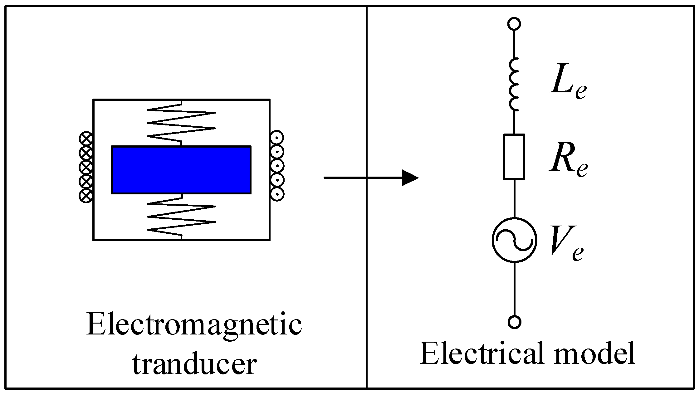
Figure 4.
Single mode shunts, (a) resistive, (b) series, (c) parallel, and (d) RL-C parallel.

Figure 5.
An Hard-Disk Drive (HDD) disk-spindle vibration control using piezoelectric bimorph shunt damping, (a) schematic diagram, reproduced with permission from [72], IOP Publishing, 2007 and (b) photograph, reproduced with permission from [73], IOP Publishing, 2007.
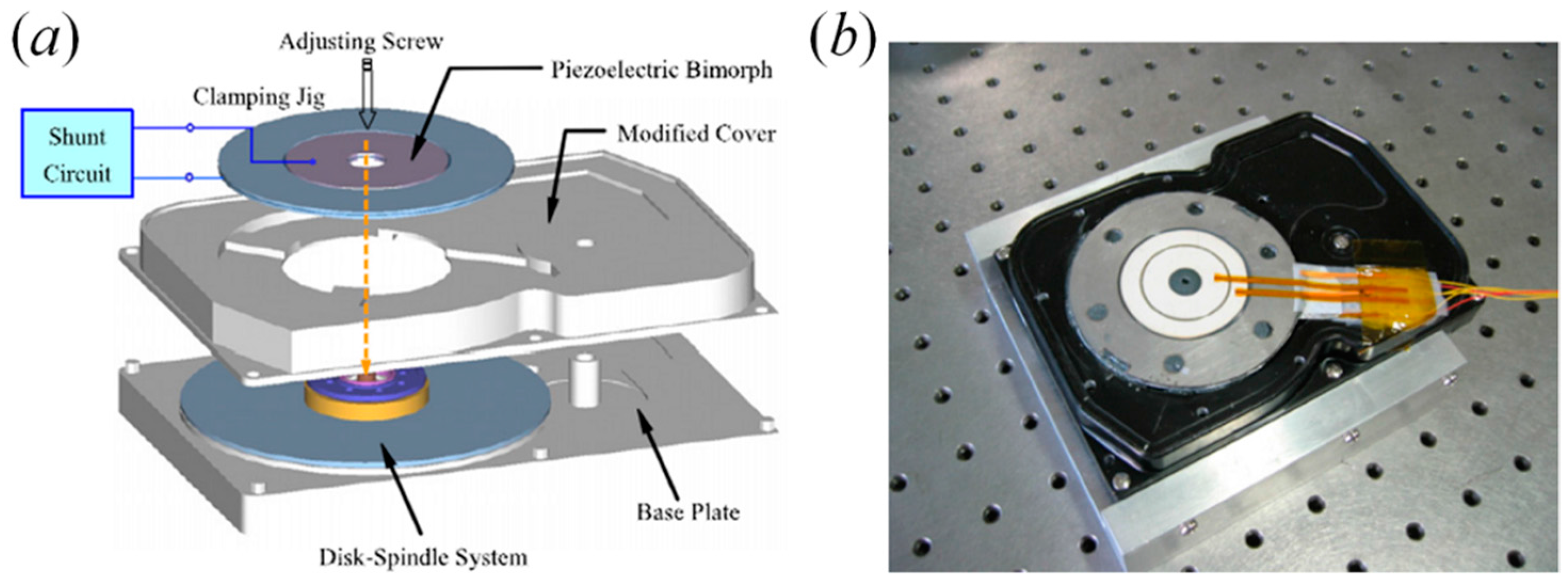
Figure 6.
(a) Series RL and (b) parallel RL shunt circuits considering dielectric loss of piezoelectric elements.
Figure 6.
(a) Series RL and (b) parallel RL shunt circuits considering dielectric loss of piezoelectric elements.

Figure 7.
Multimode shunts, (a) Hollkamp shunt; (b) current-blocking shunt; (c) current-flowing shunt; and (d) series-parallel shunt.
Figure 7.
Multimode shunts, (a) Hollkamp shunt; (b) current-blocking shunt; (c) current-flowing shunt; and (d) series-parallel shunt.

Figure 8.
(a) Schematic of the negative impedance converter (NIC), (b) negative capacitance shunt for the vibration control of a truss structure, reproduced with permission from [37], IOP Publishing, 2008.
Figure 8.
(a) Schematic of the negative impedance converter (NIC), (b) negative capacitance shunt for the vibration control of a truss structure, reproduced with permission from [37], IOP Publishing, 2008.
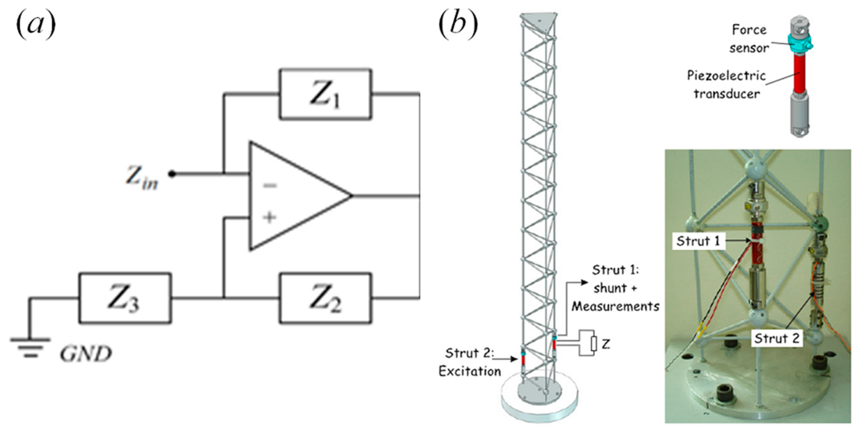
Figure 9.
(a) Schematic of a synthetic shunt impedance converter; (b) photograph, reproduced with permission from [53], IOP Publishing, 2012.
Figure 9.
(a) Schematic of a synthetic shunt impedance converter; (b) photograph, reproduced with permission from [53], IOP Publishing, 2012.

Figure 10.
Improved negative inductance circuit.

Figure 11.
Switchable shunts, (a) switch capacitor, (b) switch R-L, (c) synchronized switched damping on a resistance (SSDS), (d) synchronized switched damping on negative capacitance (SSDNC) and (e) synchronized switched damping on negative capacitance and inductance (SSDNCI).
Figure 11.
Switchable shunts, (a) switch capacitor, (b) switch R-L, (c) synchronized switched damping on a resistance (SSDS), (d) synchronized switched damping on negative capacitance (SSDNC) and (e) synchronized switched damping on negative capacitance and inductance (SSDNCI).

Figure 12.
Adaptive shunts, (a) for single mode, and (b) multimode.
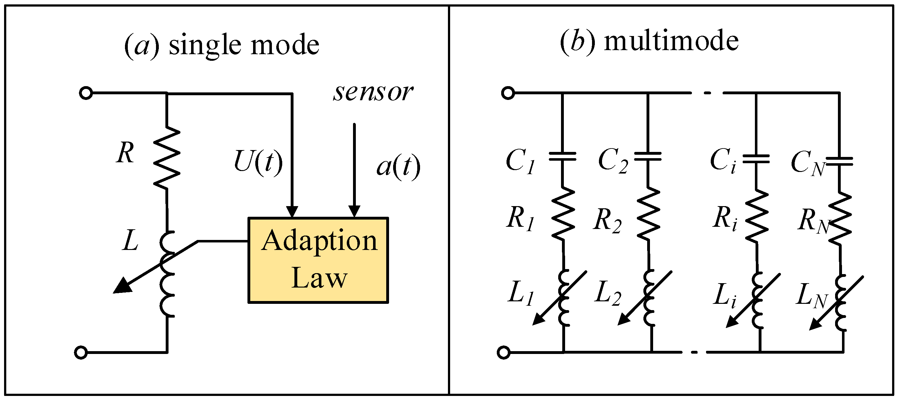
Figure 13.
Adaptive RC shunt.
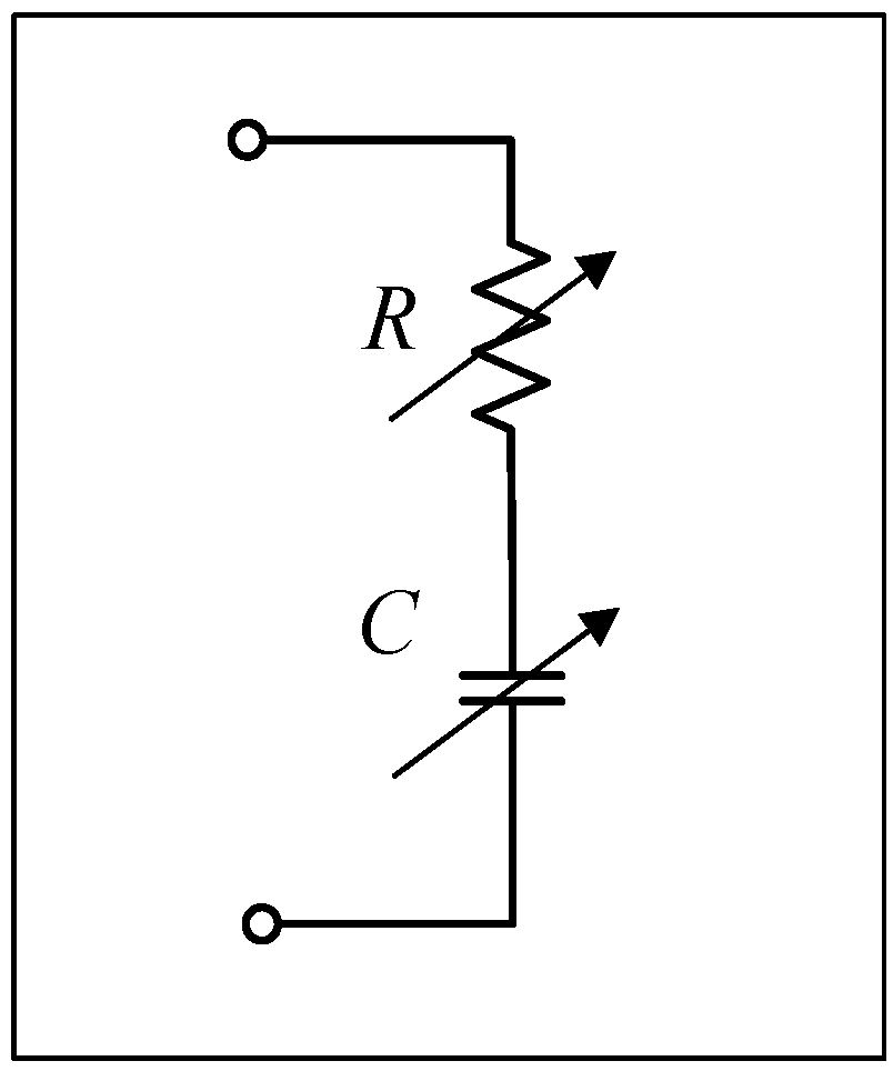
Figure 14.
Controlled negative capacitance.
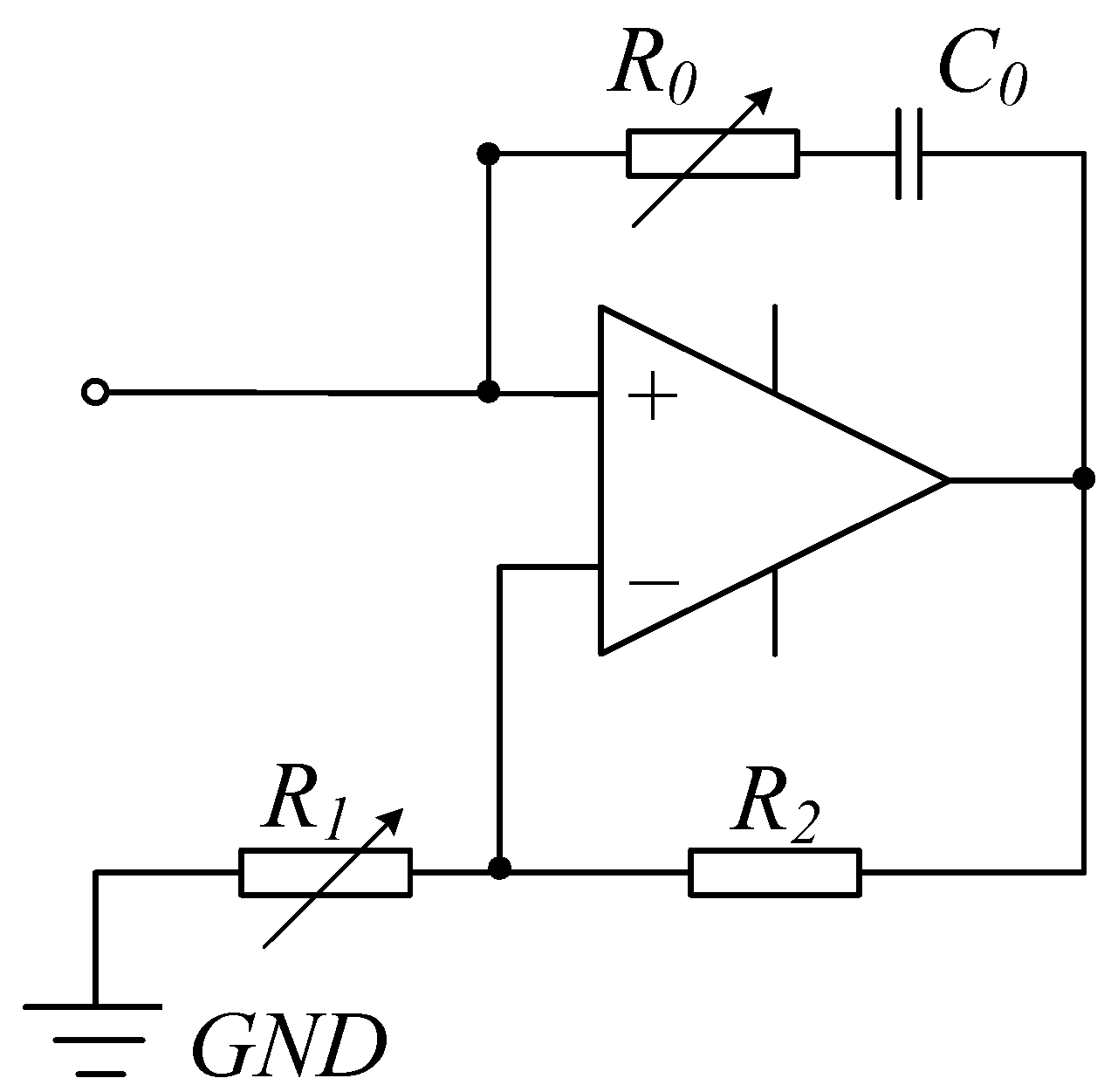
Figure 15.
Adjustable negative capacitance shunt circuit.

Figure 16.
RLC shunted piezoelectric transducers for increasing the transmission loss of a plate, reproduced with permission from [128], Academic Press, 2001.
Figure 16.
RLC shunted piezoelectric transducers for increasing the transmission loss of a plate, reproduced with permission from [128], Academic Press, 2001.

© 2017 by the authors. Licensee MDPI, Basel, Switzerland. This article is an open access article distributed under the terms and conditions of the Creative Commons Attribution (CC BY) license (http://creativecommons.org/licenses/by/4.0/).
Share and Cite
MDPI and ACS Style
Yan, B.; Wang, K.; Hu, Z.; Wu, C.; Zhang, X. Shunt Damping Vibration Control Technology: A Review. Appl. Sci. 2017, 7, 494. https://doi.org/10.3390/app7050494
AMA Style
Yan B, Wang K, Hu Z, Wu C, Zhang X. Shunt Damping Vibration Control Technology: A Review. Applied Sciences. 2017; 7(5):494. https://doi.org/10.3390/app7050494
Chicago/Turabian StyleYan, Bo, Ke Wang, Zifan Hu, Chuanyu Wu, and Xinong Zhang. 2017. "Shunt Damping Vibration Control Technology: A Review" Applied Sciences 7, no. 5: 494. https://doi.org/10.3390/app7050494
Note that from the first issue of 2016, this journal uses article numbers instead of page numbers. See further details here.