1. Introduction
The high and low-voltage parallel loop is a kind of power grid structure, in which transmission lines of different voltage levels are looped by transformers at the sending and receiving ends. With the rapid development of higher-voltage power grids, parallel loops [
1] have become more and more common. Parallel flow in a parallel loop would make unbalanced power flow in a power system, which leads to higher power losses. In some cases, parallel loop would even threaten the security and stability of a power system [
2]. On the one hand, low-voltage transmission lines of parallel loops would bear a quite heavy load after faults on high-voltage transmission lines, which may cause cascading trips of low-voltage transmission lines [
3]. On the other hand, parallel operation of high- and low-voltage transmission lines also leads to a high level of short circuit current, which may exceed the interrupting capacity of circuit breakers. Therefore, considering energy saving and system security and stability, some methods must be presented to solve these problems.
There are many studies that have tried to apply Flexible AC Transmission System (FACTS) technologies to eliminate parallel flow or control power flow in parallel loops [
1,
2,
3,
4]. These studies only improve the operational characteristics of power systems, however, they cannot solve the problems caused by parallel loops radically from the aspect of power grid structure. Especially for higher-voltage power grids, the use of FACTS is quite limited. Fortunately, it has been proved that switching specific transmission lines could make power flow more balanced [
5], reduce power loss [
6] and decrease short circuit current [
7]. And some studies have been carried out to find the optimal line switching scheme [
8,
9]. Accordingly, the parallel loop problem mentioned above can be solved by switching specific low-voltage transmission lines at appropriate location and time. However, it is difficult to describe this problem as an accurate mathematical model [
10]. It is actually a complicated mixed-integer programming problem, which is multi-objective, non-linear and discrete. In order to simplify the calculation complexity, the decision process of opening parallel loops is usually divided into two stages: scheme generation and scheme evaluation.
The generation of opening schemes used to only depend on engineering experiences. But things are changing gradually. There are studies employing linear programming algorithms to find the optimal line switching scheme with minimum power loss [
11,
12]. These studies only consider the branch active power flow constraint, and the bus voltage constraint is neglected. Simulation results in [
13] show that the neglect of bus voltage constraint may cause the failure of optimization. A line switching optimization method considering bus voltage constraint is proposed in [
14], which could effectively eliminate over-limited power flows. In [
15], the Benders decomposition technology is applied to network reconfiguration, which could deal with the constraints of static security and transient stability simultaneously. But this method is barely able to be used in actual large-scale power systems, due to its high complexity.
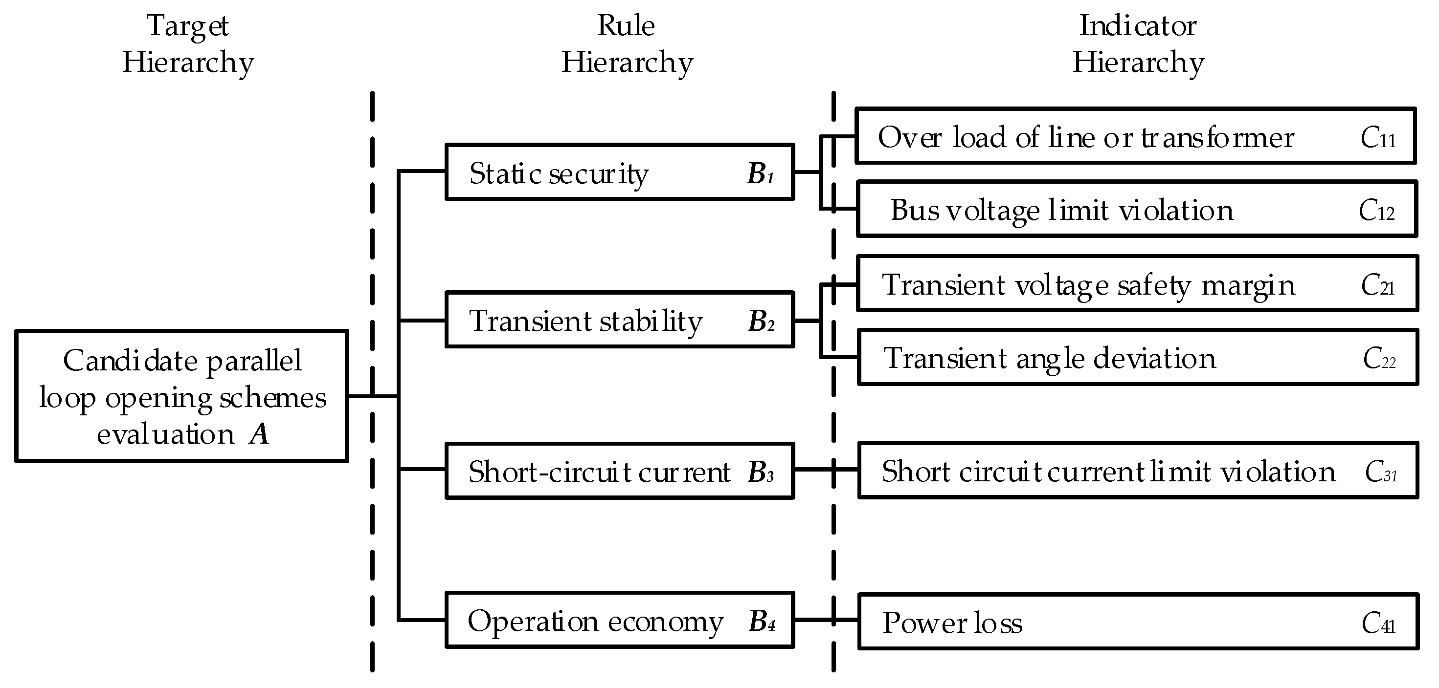
The evaluation of opening schemes should consider static security, transient stability, short circuit current and operation economy of power systems. A comprehensive evaluation method for opening schemes is proposed in [
16], which combines AHP (analytic hierarchy process) with fuzzy evaluation algorithms. The AHP is used to establish the hierarchical model to describe the operational characteristics of power systems. In this model, five performance indices and corresponding membership functions are presented. After detailed analysis and calculations for each opening scheme, the optimal one is obtained by two-level fuzzy evaluation.
All of the previous studies only discuss parallel loop opening issues in pure AC power grids. But things in AC/DC interconnected power grids would be quite different, usually more complicated indeed. The significant contributions of this paper are just at this area. Due to intensive loads in a relatively narrow region, several HVDC (high-voltage direct current) inverter stations would emerge in adjacent areas of the same AC power grid, called the multi-infeed HVDC configuration. In this situation, switching transmission lines, on the one hand, would decrease short circuit current, and, on the other hand, would stretch the electrical distance between different HVDC inverter stations. As a result, the multi-infeed short-circuit ratio (MISCR) may be increased or decreased under different conditions, which means the stability of power systems would be influenced [
17]. Therefore, the decision for the optimal parallel loop opening scheme must consider the support ability for HVDCs, which is evaluated by MISCR. In this paper, a decision optimization method is proposed, which coordinates the relationship between parallel loop opening effect and support ability for multiple HVDC links. Thus, this method can be used to solve the parallel loop problem not only in pure AC power grids but also in AC/DC interconnected power grids, which distinguishes the proposed method from previous research.
The decision optimization method is expounded in this paper. In
Section 2 the complex network theory used for opening parallel loops is discussed in detail. GN algorithm and modularity indicators are introduced. In
Section 3 the generation process of candidate opening schemes is proposed. The weighted modularity indicator and weighted MISCR are defined respectively, and combined to filter generated opening schemes. In
Section 4 an evaluation model for candidate schemes is founded based on AHP, which considers the relationship between stability and short circuit current level of a power system. A fuzzy evaluation algorithm is used to find the optimal opening scheme. In
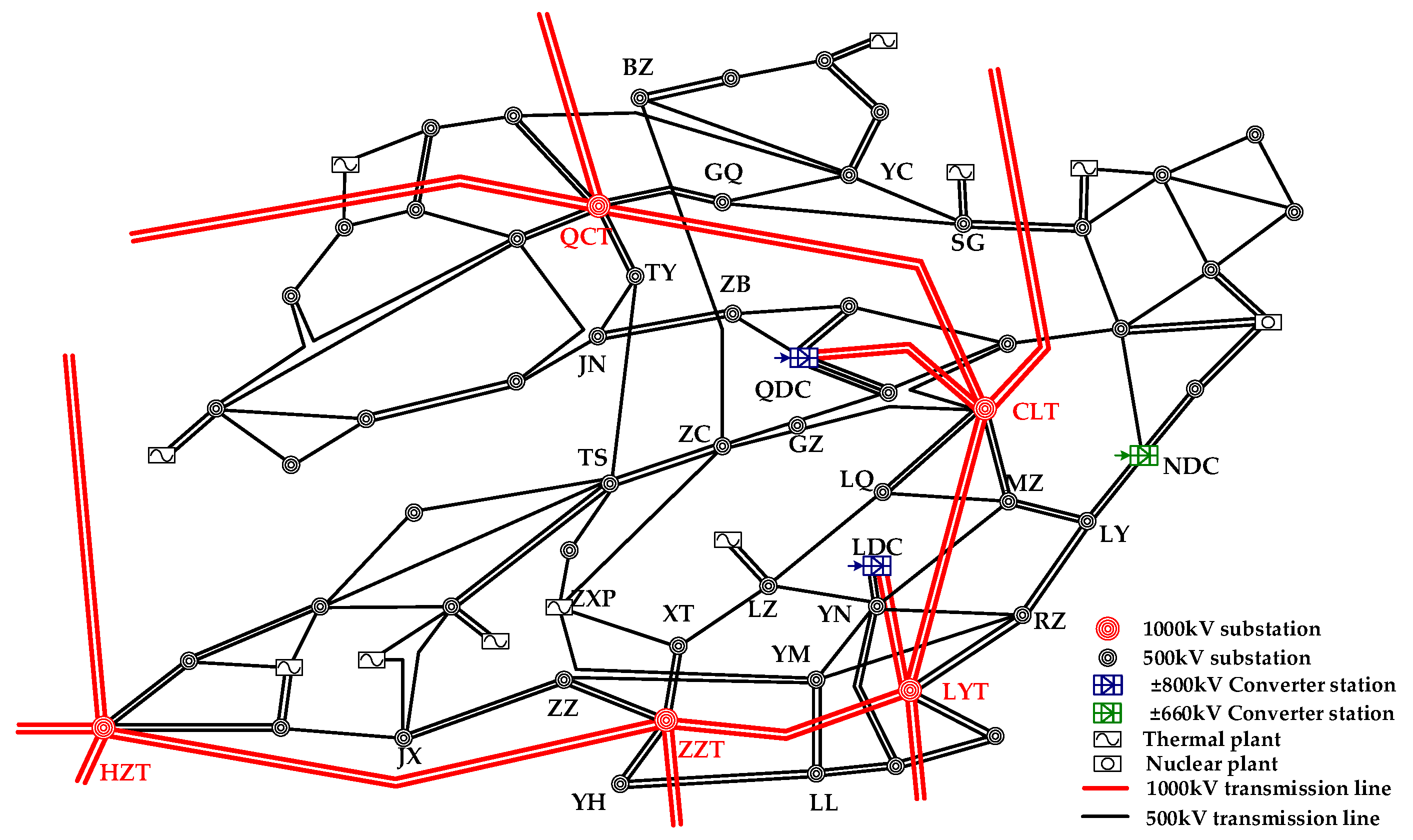
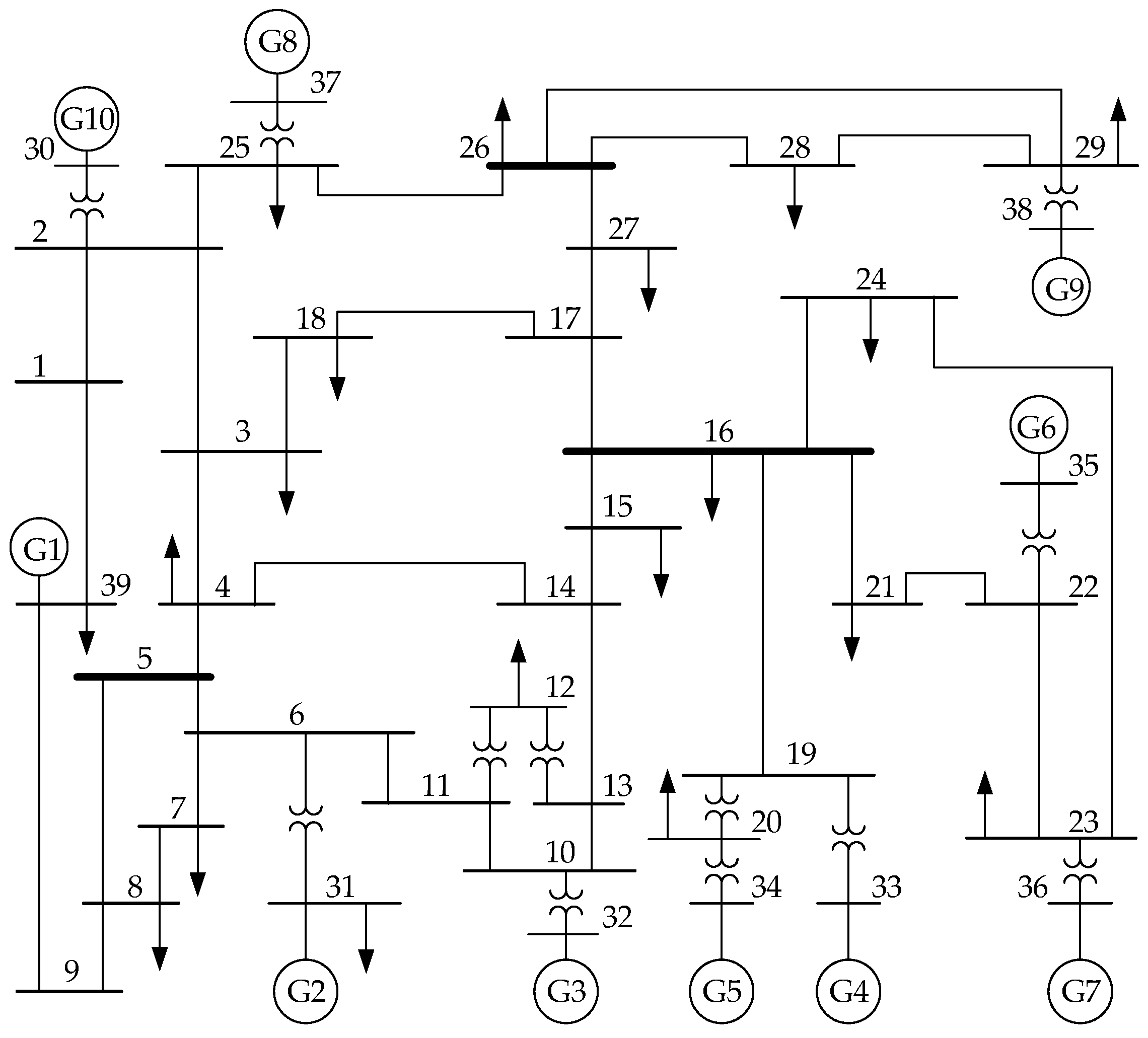
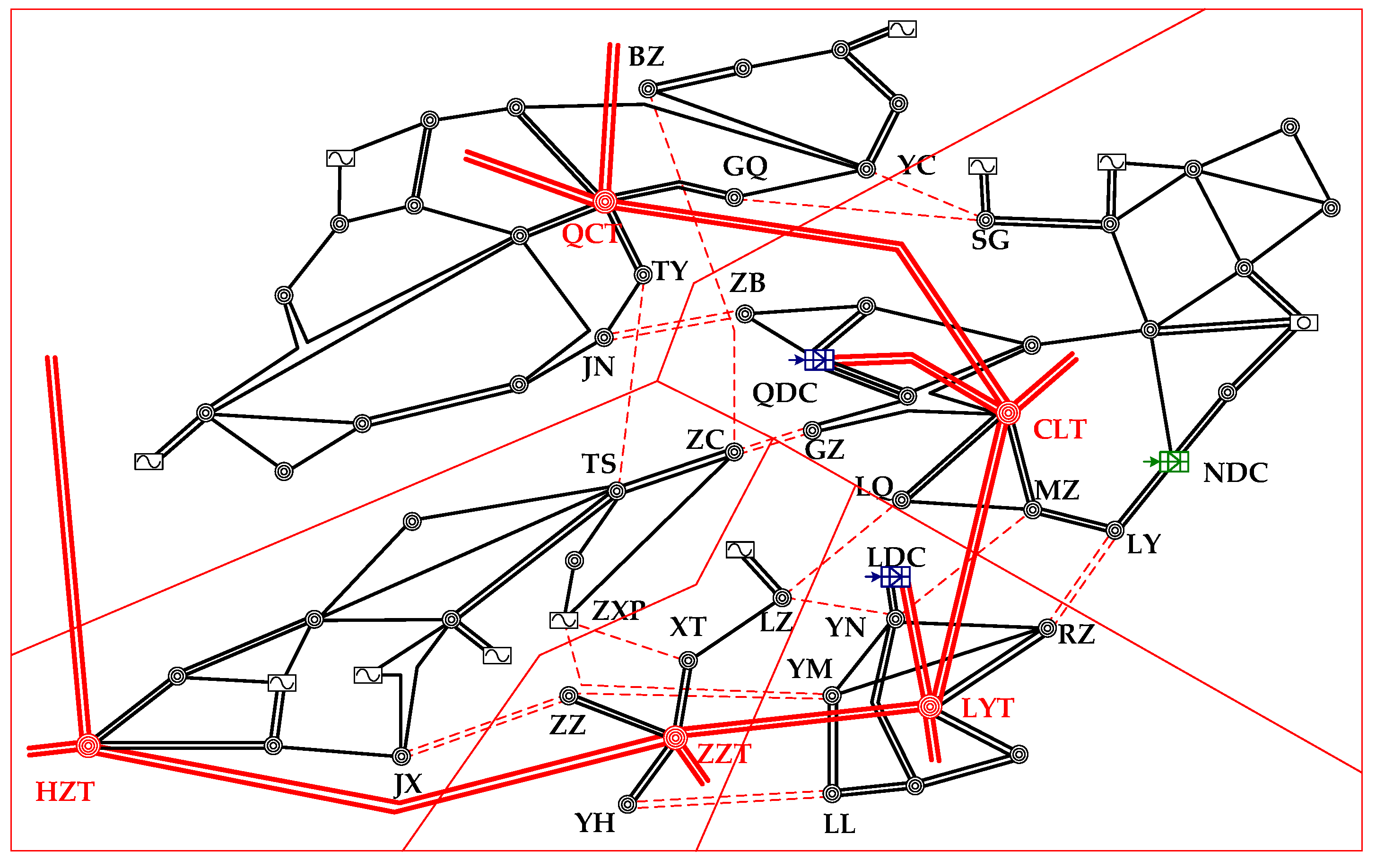
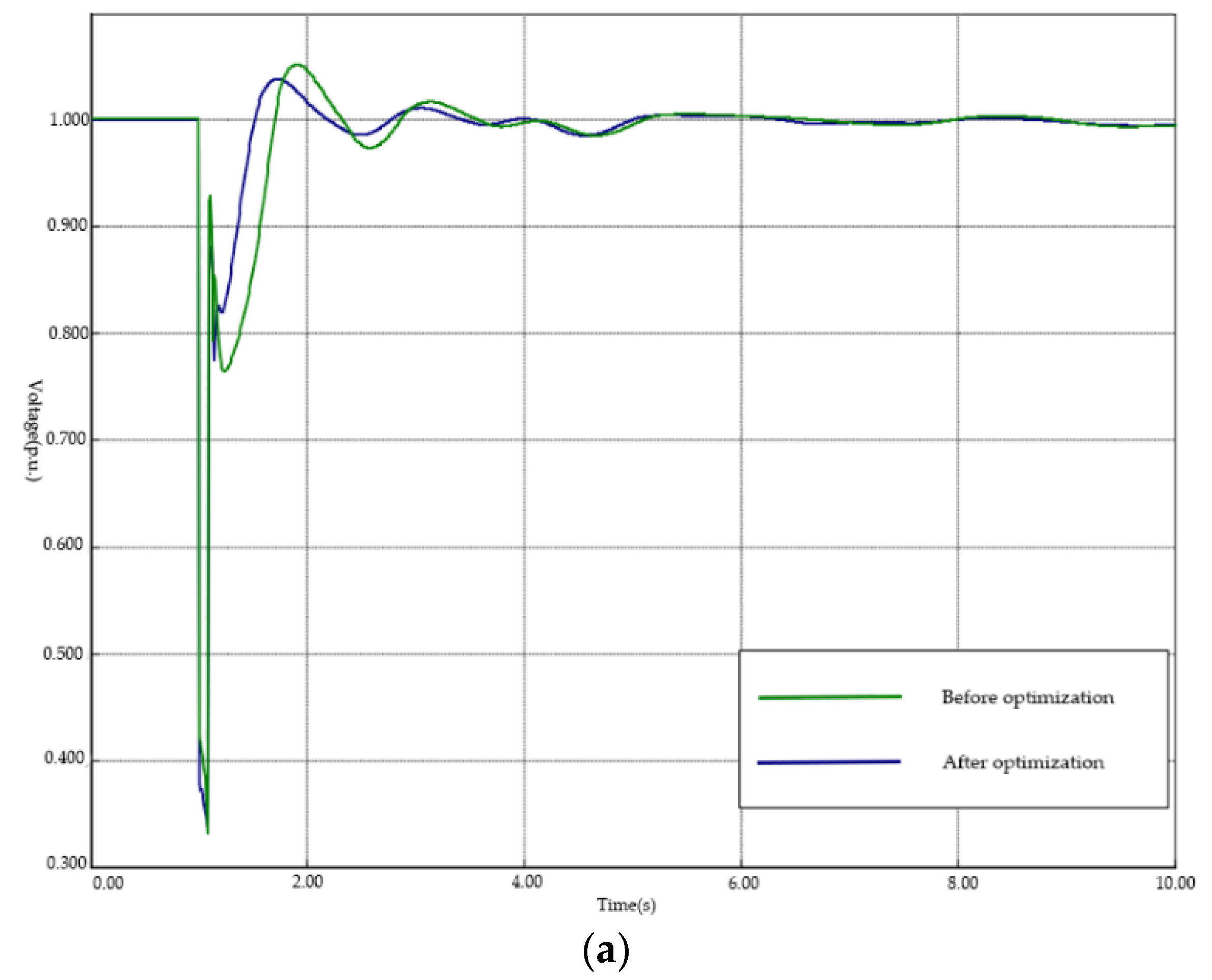
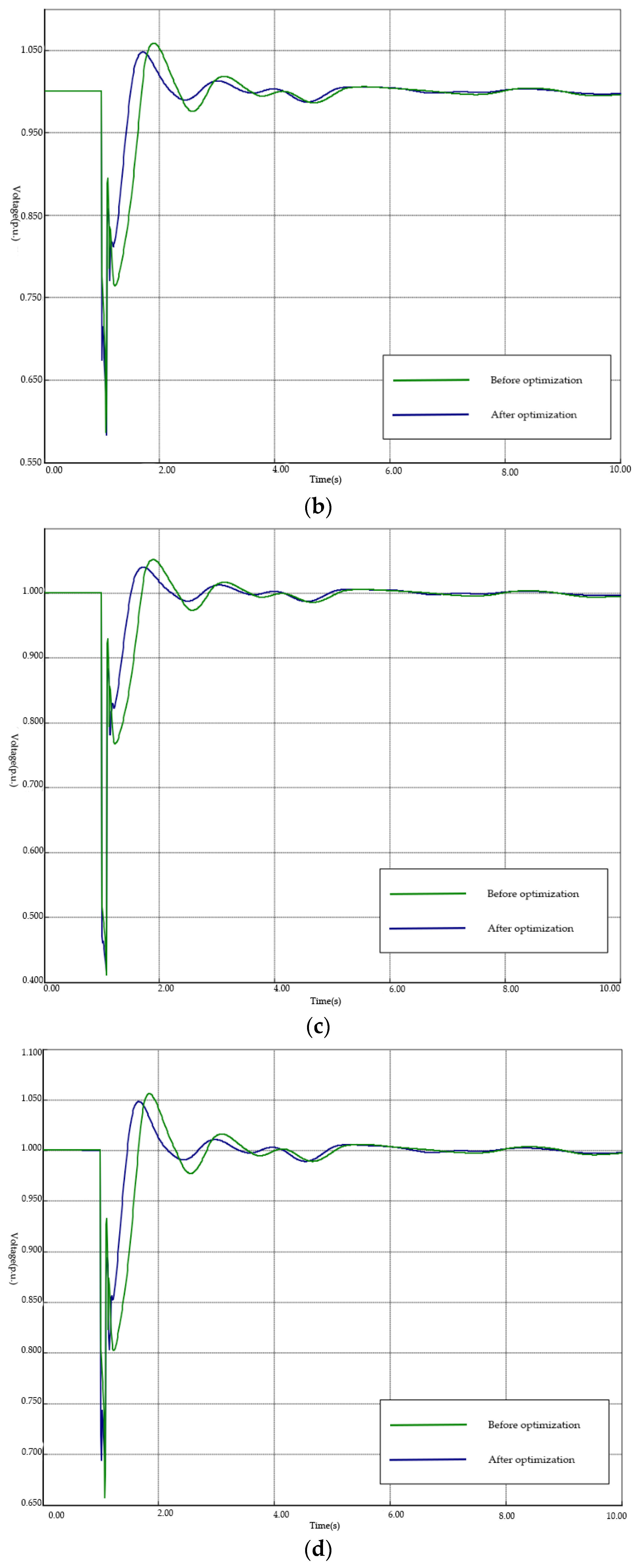
Section 5 a New England 39-bus system and an actual power system are analyzed. Simulation results validate the effectiveness and superiority of this proposed method.
3. Generation of Parallel Loop Opening Schemes
3.1. Weighted Network and Weighted Modularity Indicator
The original GN algorithm can only be applied in unweighted networks. In an unweighted network, the existence of an edge only means that the nodes on the two ends of the edge are connected. No more information is contained in the edge. However, most of actual networks, especially power grids, are weighted networks, where weights of network edges have practical significance. The edges in weighted networks can contain information about how the nodes on the two ends of the edge are connected or how closely they are connected. This information is represented by edge weights. If a weighted network is analyzed as an unweighted network, the information contained in weights will be lost, which will influence the reasonableness of analysis results. To solve this problem, Newman found a way to convert the weighted network to multigraph, which makes GN algorithms applicable in weighted networks [
23].
For a power grid network, better community separating results can be derived if the edge weights are considered in the separating process. Considering the length and physical parameters of transmission lines in power grid networks, the modulus value of branch admittance is defined as the edge weight. The weight of an edge in a complex network usually represents the connection tightness of the two nodes connected by this edge. Thus, the larger the admittance modulus value of a branch, the shorter the electrical distance between two substations connected by this branch.
In a weighted complex network, the weighted edge betweenness can be defined as the ratio of the edge betweenness obtained from the corresponding unweighted network and the weight of this edge. Thus, a larger edge betweenness and a smaller weight value would jointly make a larger weighted edge betweenness of this edge, whose possibility of being removed from the network in community separating process would be larger.
Based on the edge weight defined above, the weighted modularity indicator can be derived from (2) as:
where
Svw is the weight of the edge connecting node
v and
w.
3.2. Weighted Multi-Infeed Short Circuit Ratio
With the development of HVDC transmission systems, parallel loops might emerge in typical multi-infeed HVDC configurations. MISCR can represent the interactions between AC and DC systems and among different DC links in AC/DC interconnected power systems [
24]. A practical definition of MISCR based on impedance matrix can be derived as [
25]:
where
Uaci is the inverter bus voltage of the
i-th DC; and
Zeqij is the element of the equivalent impedance matrix
Zeq, which can be obtained by multi-port Thevenin equivalent method. It should be noted that the value of
Zeqij is equal to the voltage of node
i when unit current is only being injected to node
j.
It is obvious that opening parallel loops would change the elements of the equivalent impedance matrix Zeq. Thus, it can be deduced from (8) that opening parallel loops would influence the MISCR of each DC link, which indicates system stability would be influenced by any parallel loops opening scheme. In general, system stability should not descend a lot after opening parallel loops. In order to evaluate the influence of opening schemes on system stability in multi-infeed HVDC configurations, the evaluation index must be defined based on MISCR.
Although the stability of multi-infeed HVDC systems is determined by all of the infeed DC links, the contribution of each DC link is different. Based on this evidence, the system stability evaluation index can be defined as the weighted MISCR, which is derived as:
where
n is the number of DCs;
MISCRi is the multi-infeed short-circuit ratio of the
i-th DC; and
ωi is the weighted factor of the
i-th DC, which represents the importance of the
i-th DC. A larger value of
ωi indicates greater importance of
i-th DC and greater influence on other DCs.
Obviously, the weighted factor ωi is quite essential to define the weighted MISCR, which must meet three requirements:
- (a)
The weighted factor should not be assigned a value manually;
- (b)
The weighted factor should represent the interaction between different DC links; and
- (c)
The weighted factor should represent the contribution to system stability of the specific DC link.
To define the weighted factor
ωi, the definition of MISCR should be analyzed firstly. Equation (8) can be transformed as:
where
μi is a penalty factor. It should be noted that
Saci/Pdi is the definition of single-infeed short circuit ratio (SISCR) without considering the interaction between different DC links. Based on the physical meaning of SISCR, a small
μi indicates the
i-th DC can be influenced by other DCs easily, which means a smaller contribution to system stability. Thus, this penalty factor can represent the importance of the
i-th DC in multi-infeed DC systems.
Thus, the weighted factor of the
i-th DC can be defined as:
where
Zeqij is the equivalent mutual-impedance between the
i-th DC and the
j-th DC;
Zeqii is the equivalent self-impedance of the
i-th DC; and
Pdi and
Pdj are the rated transmission powers of the
i-th DC and the
j-th DC, respectively. The definition of (11) considers not only the electrical distance, but also the transmission capacity of a DC link, which fulfills the three requirements above.
3.3. Generation Process
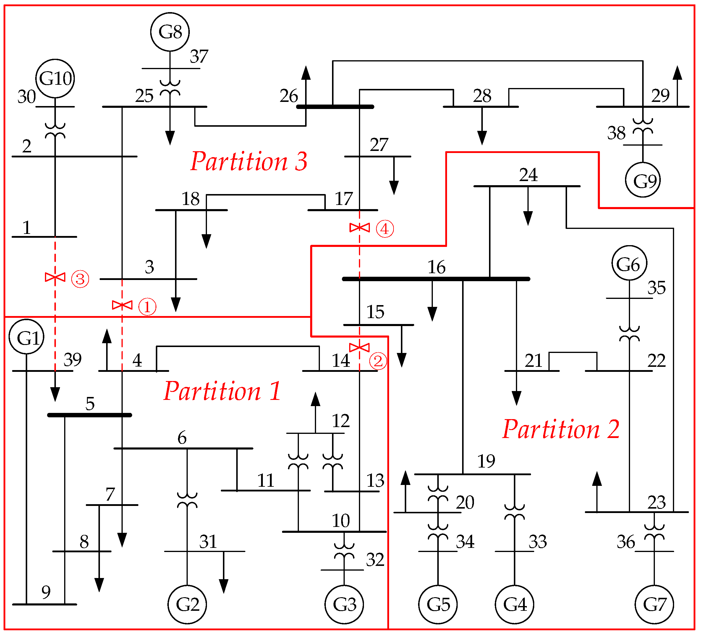
For parallel loop opening issues, the situation that a lower-voltage isolated power grid partition is separated from the main grid should be avoided. Thus, power substations in higher-voltage power grids are usually selected as hub substations. And each power grid partition consists of at least one hub substation. The maximum possible number of partitions is determined by the number of hub substations. The parallel loop opening process should be stopped when all hub substations are divided into different partitions by GN algorithm.
The generated partitions, each of which contains one hub substation, can be defined as basic partitions. Neighboring basic partitions can be combined in different ways to generate different parallel loop opening schemes. An actual AC/DC interconnected power grid contains many higher voltage substations, which usually leads to a huge number of candidate opening schemes. It is usually not necessary to evaluate each of these generated schemes using comprehensive evaluation models because of huge computation times. Thus, a filtering strategy is needed.
According to the analysis above, the weighted modularity indicator can be used to filter the generated opening schemes preliminarily in pure AC power grids. But in AC/DC interconnected power grids, where the influence on MISCR of generated opening schemes must be considered, it is obviously not appropriate to filter opening schemes only based on weighted modularity indicator. Thus, a new filtering index is defined as:
where
λ1 and
λ2 are the weighted coefficients, respectively. There exists the relationship
λ1 +
λ2 = 1. It should be noted that
λ1 and
λ2 are normalized values, not the real algebraic values. The new filtering index is applicable to not only AC/DC interconnected power grids, but also pure AC power grids with
λ1 = 1,
λ2 = 0.
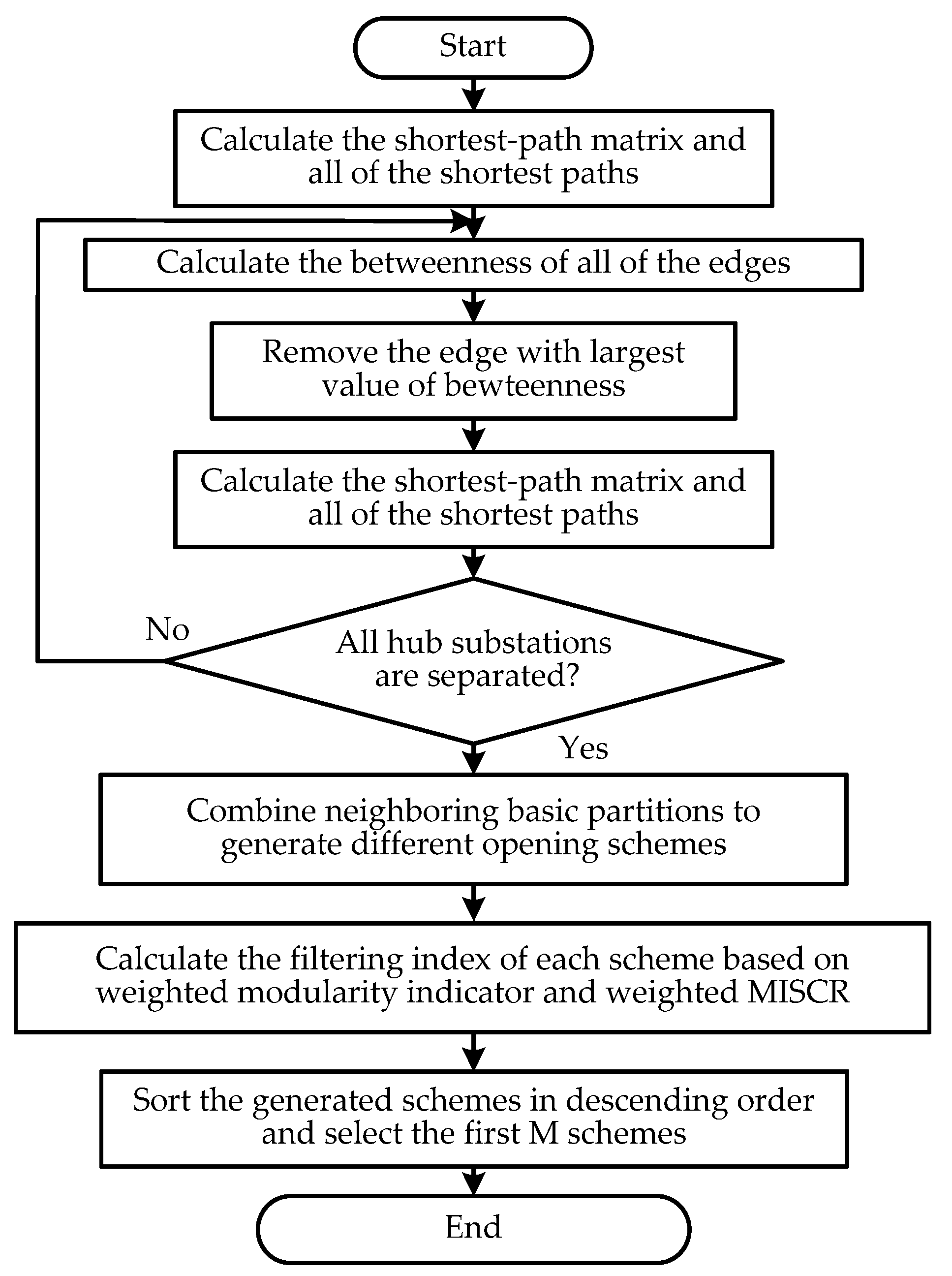
All of the generated opening schemes are sorted in descending order according to the filtering index defined in (12) and the first
M schemes are selected as candidate schemes to find the optimal one. The generation process of parallel loop opening schemes is shown in
Figure 1, where the shortest-path matrix can be used to judge whether each hub substation is divided into different partitions.


