
Preliminary Study on the Damping Effect of a Lateral Damping Buffer under a Debris Flow Load


Abstract
:
1. Introduction
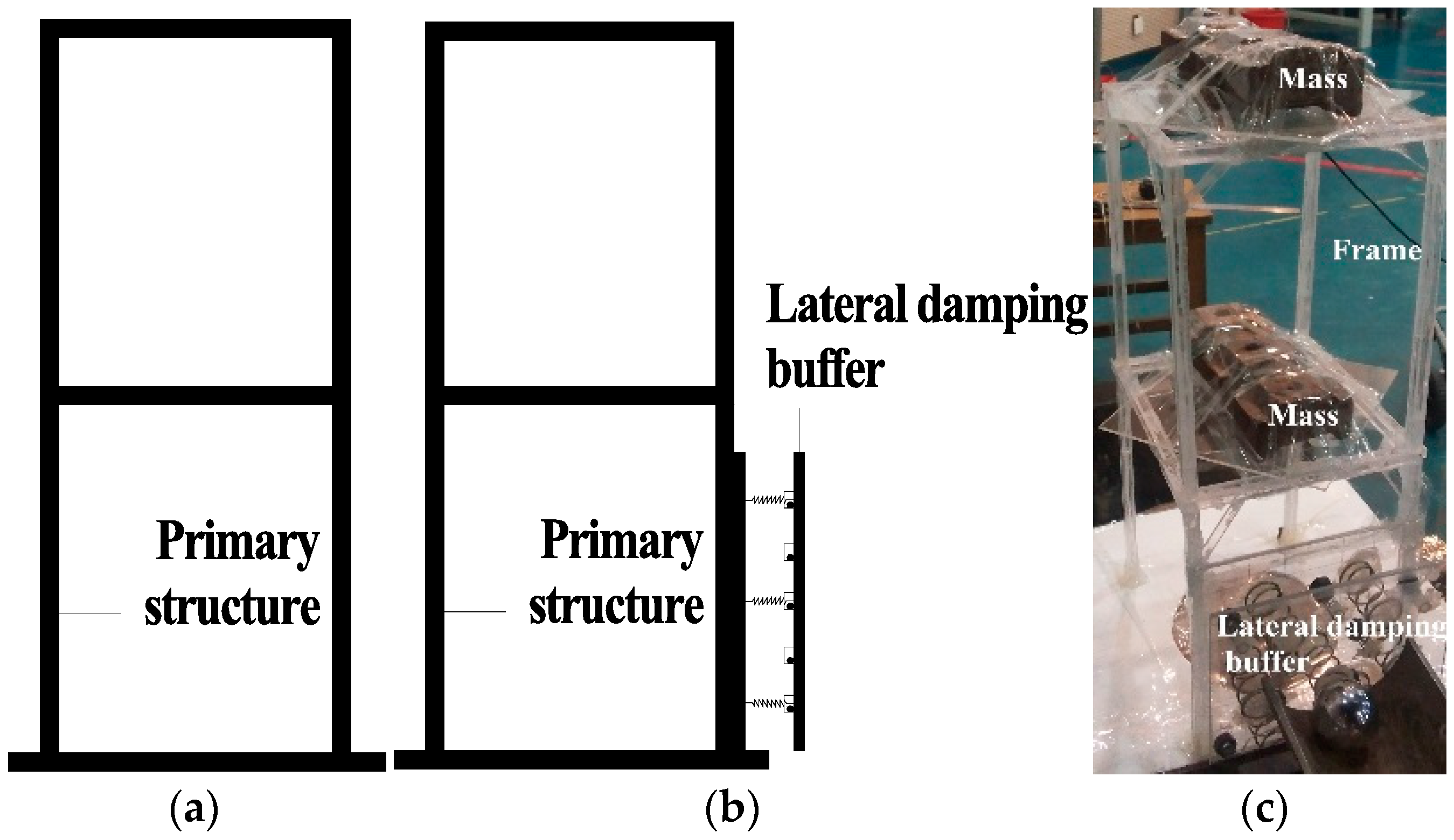
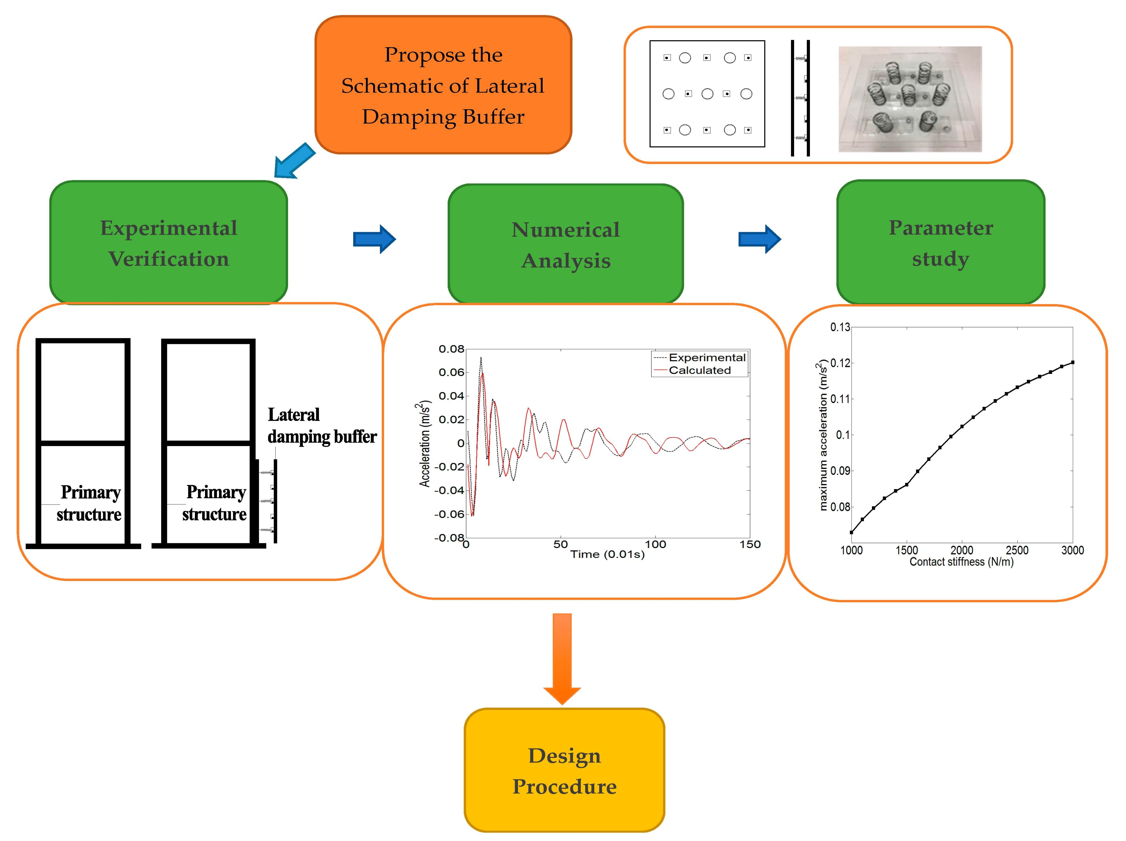
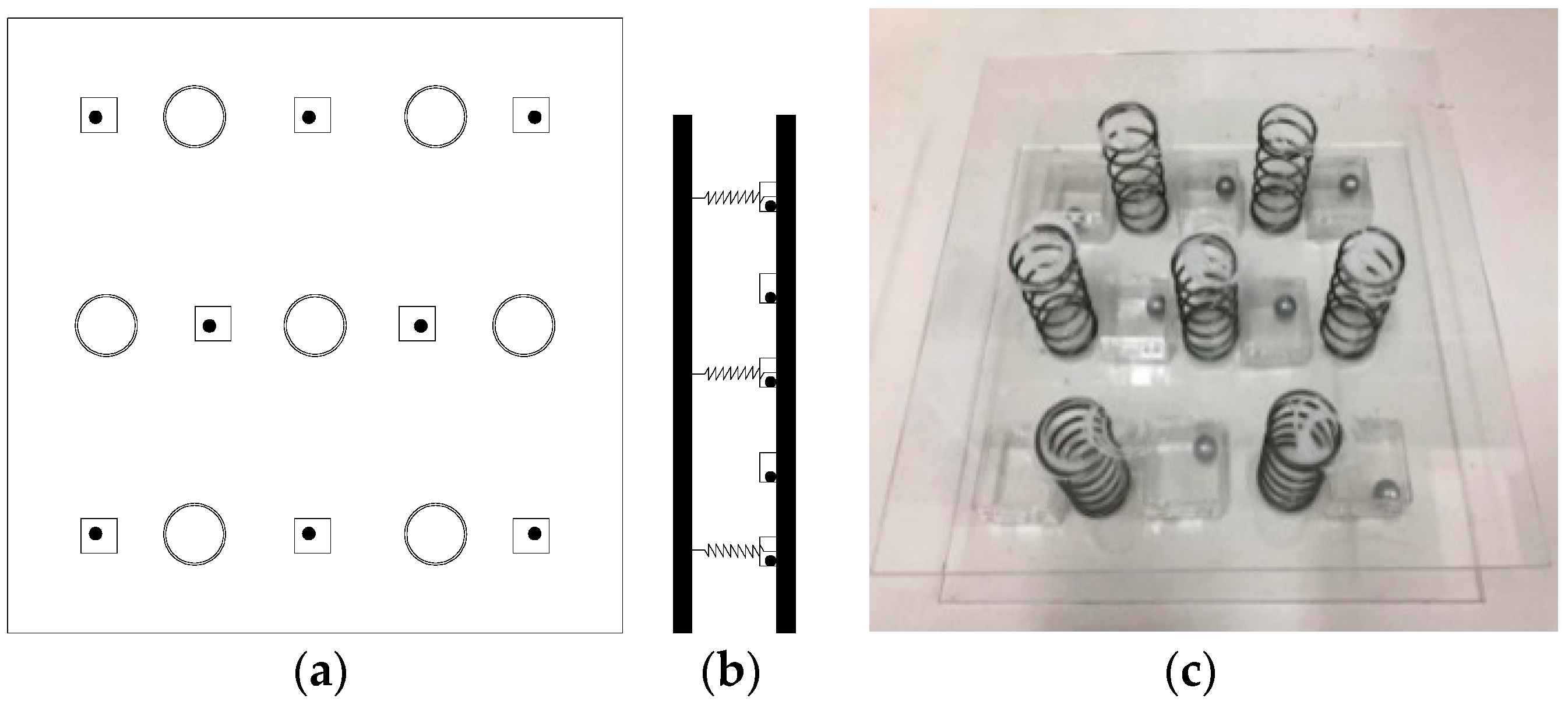
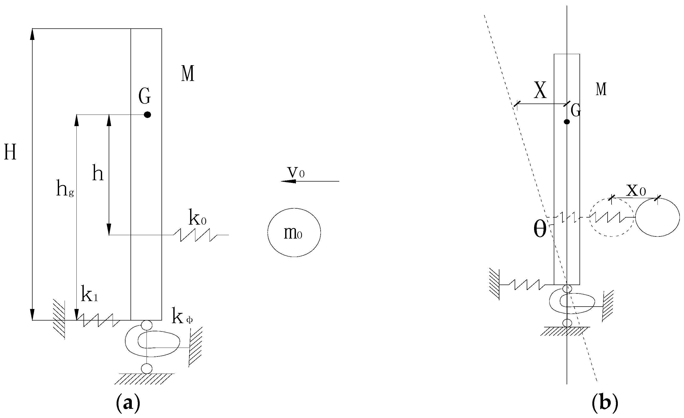
2. Schematic of a Lateral Damping Buffer
3. Experiment Validation
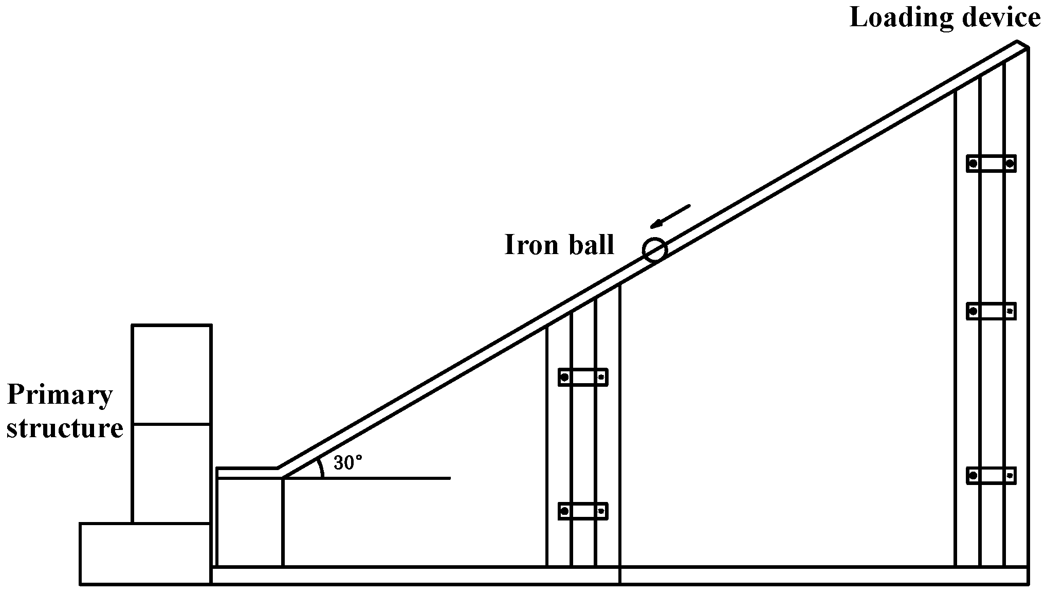
3.1. Experiment Design
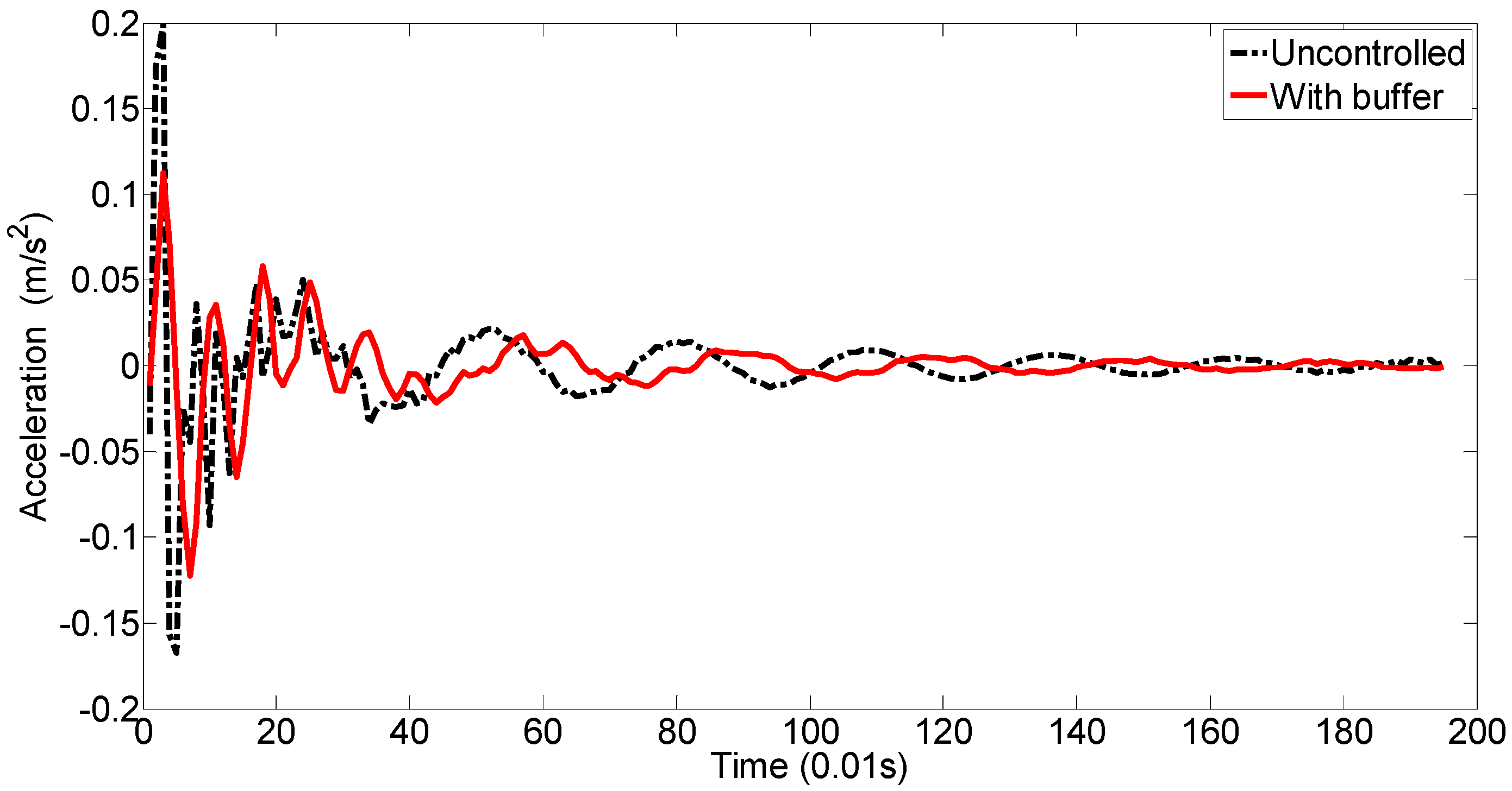
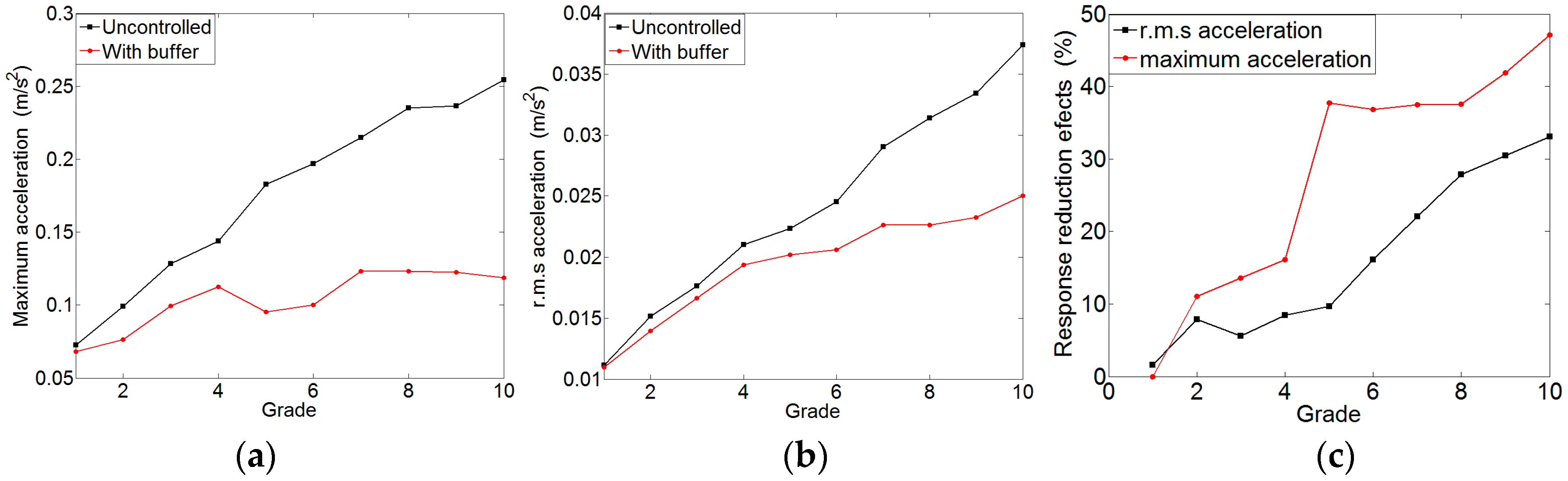
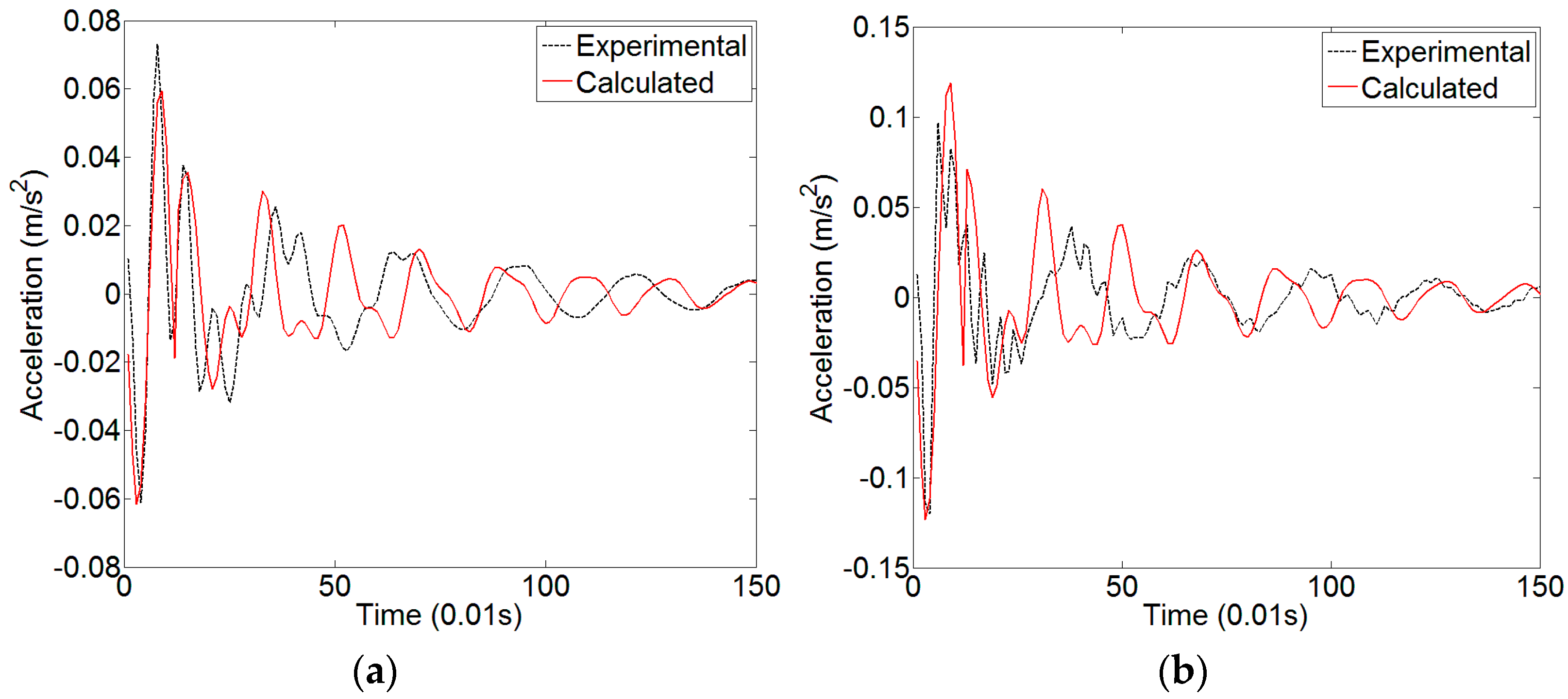
3.2. Responses in Time Domain
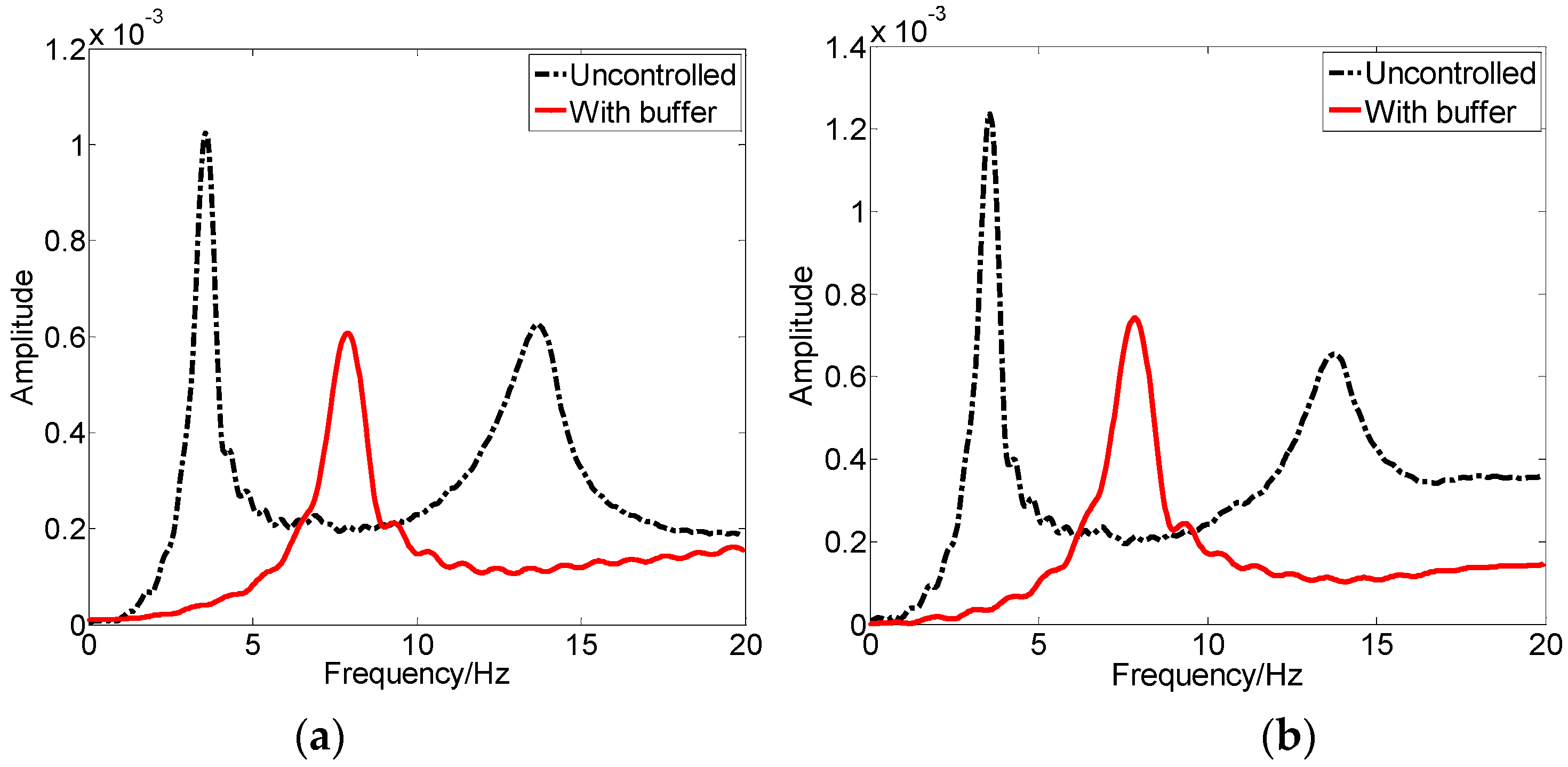
3.3. Responses in Frequency Domain
- (1)
- The Fourier spectrum of the acceleration time history curve of the uncontrolled structure has two obvious peak values in the vicinity of 3.6 Hz and 14 Hz respectively, which correspond to the measured natural frequencies. However, the Fourier spectrum of the structure with buffer has just one peak value in the vicinity of 8 Hz, since the attachment of the buffer has strengthened the integrity of the structure.
- (2)
- As for the amplitude, the response of the structure with a buffer is clearly reduced. That is, the vibration of the structure is under control and the lateral damping buffer has good effects.
- (3)
- The Fourier spectral lines show the distribution of the vibration power of the primary structure in the frequency domain. The area under the Fourier spectral line of the structure with the buffer is smaller than that of the uncontrolled one, which shows the lateral damping buffer can greatly decrease the vibration energy of structures.
- (4)
- Compared the response under fourth loading grade and sixth loading grade, the latter is evidently smaller than the former, indicating that with increasing impact, the buffering and vibration controlling effects of the device will increase.
3.4. Equivalent Damping Ratio
4. Numerical Simulation
4.1. The Cushion Phase
4.2. The energy Dissipation Phase
4.3. Calculation Parameters
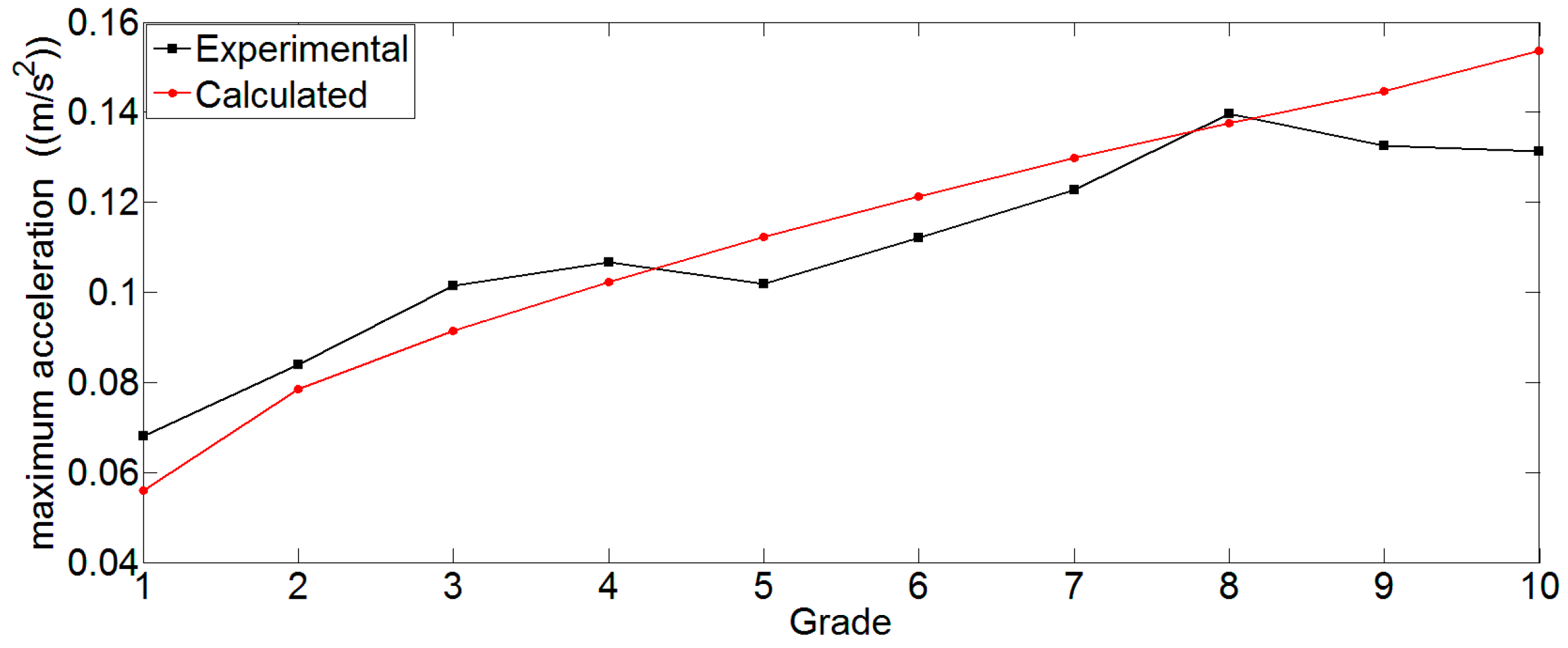
4.4. Calculation Results
4.5. Parametric Study
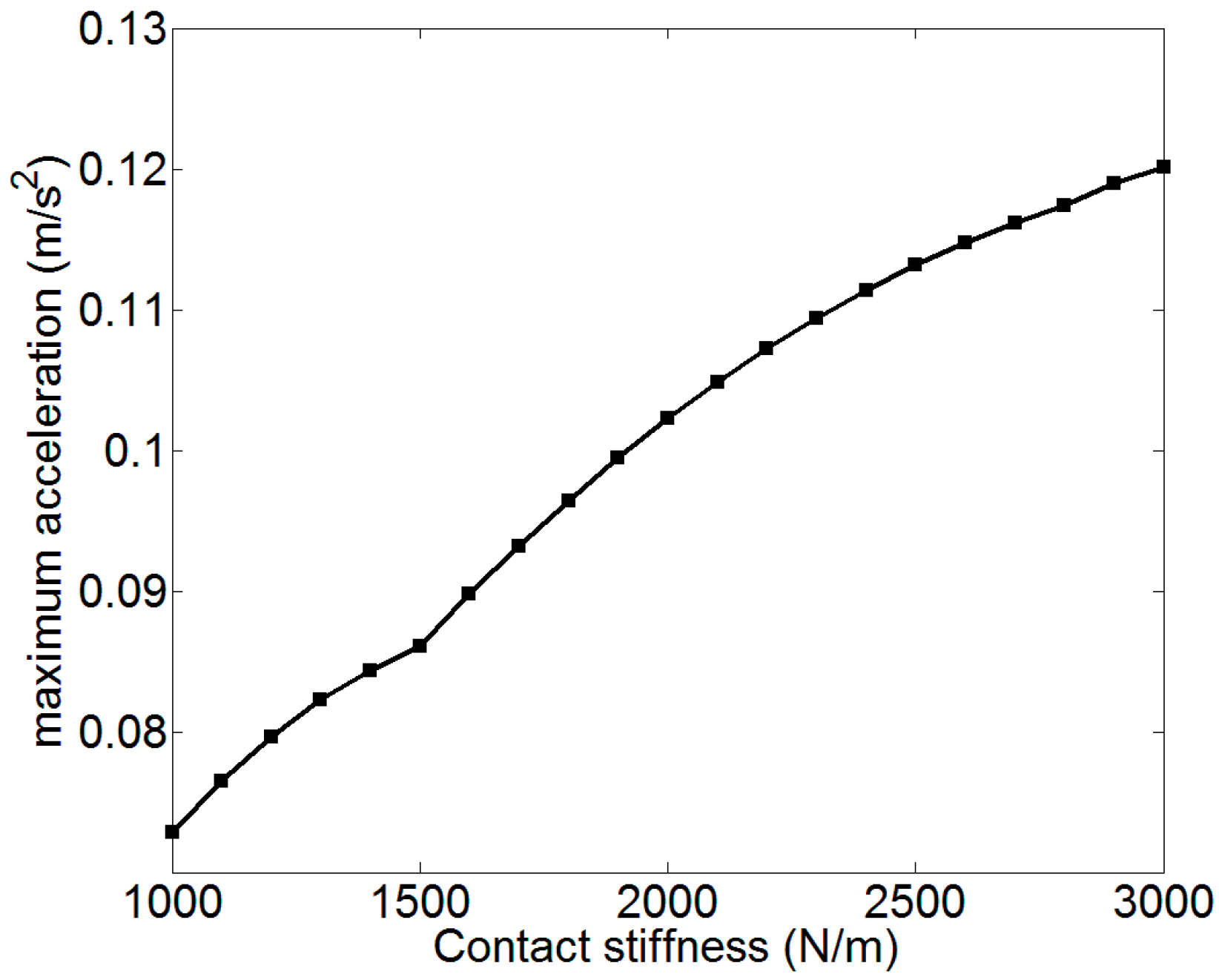
4.5.1. Contact Stiffness
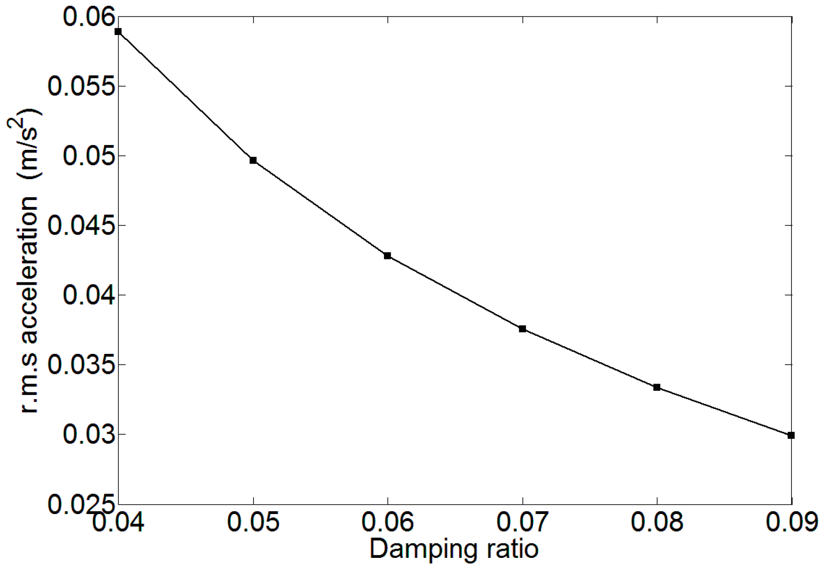
4.5.2. Damping Ratio
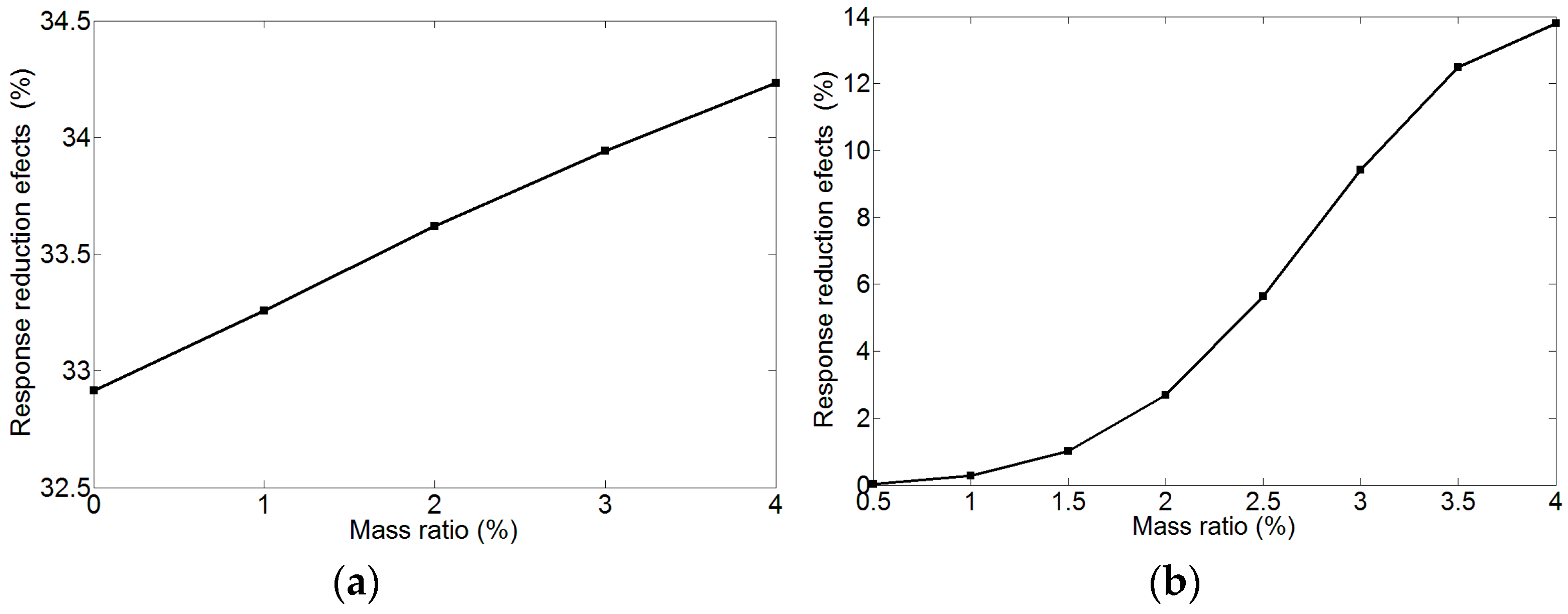
4.5.3. Mass Ratio
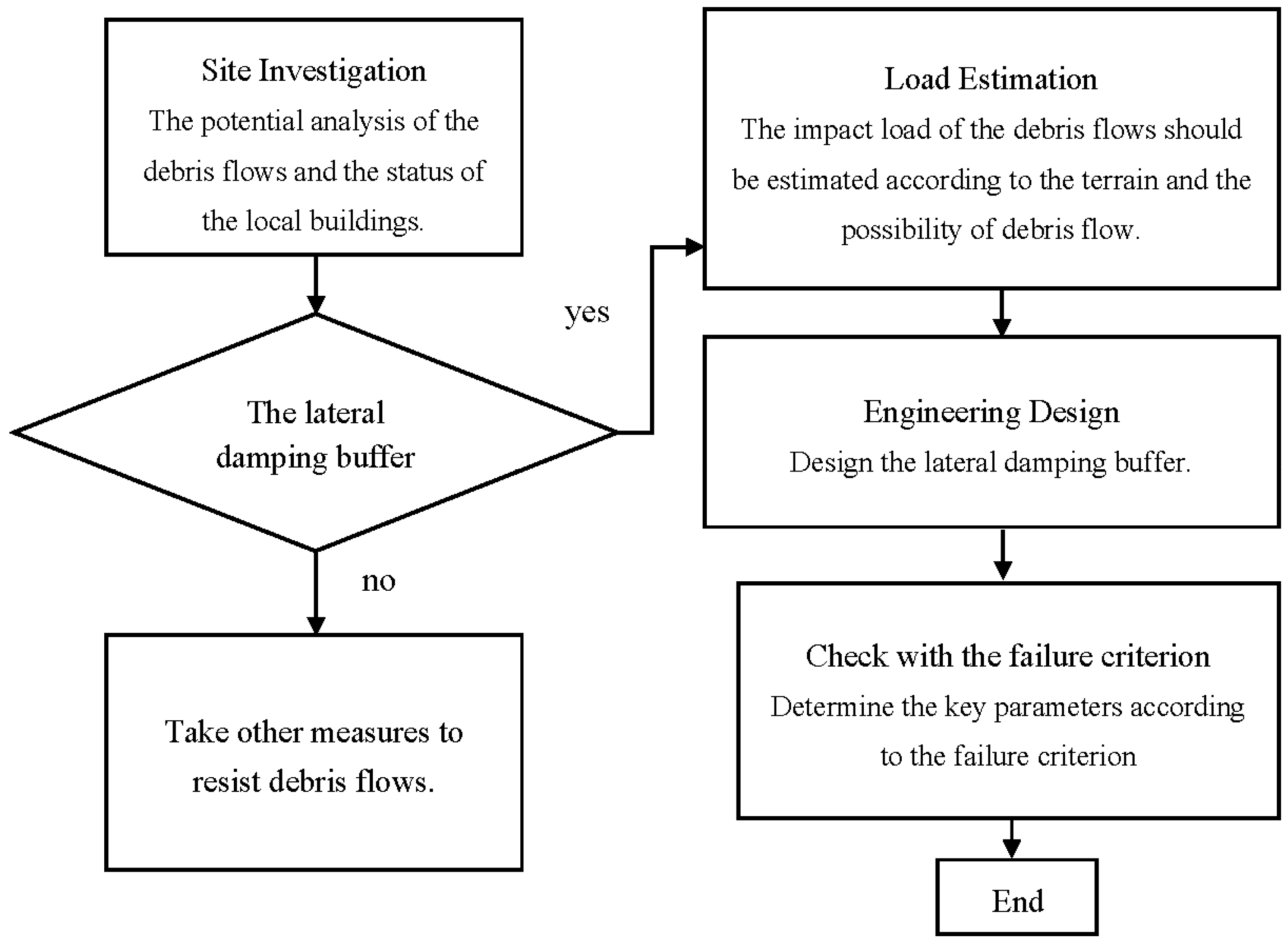
5. Design Procedure
- (1)
- The size of the boards should be determined based on the specific engineering information of the target area, especially the statistical characterizations of the vulnerable debris flows. The length of the boards should be equal to the length of target buildings facing debris flows, and the height should be determined by the impact height of debris flows. For example, the height of the board can be twice of the height of the impact height;
- (2)
- The stiffness of the springs should be determined by numerical simulation and the actual circumstance, considering the debris flow load, spring deformation limit and disaster reduction effect synthetically. Generally, a relative “soft” spring is preferred according to the parametric study. However, its stiffness is also constrained by the workability under the impact load of debris flows;
- (3)
6. Conclusions
Acknowledgments
Author Contributions
Conflicts of Interest
References
- Osti, R.; Egashira, S. Method to improve the mitigative effectiveness of a series of check dams against debris flows. Hydrol. Processes 2008, 22, 4986–4996. [Google Scholar] [CrossRef]
- Hu, K.H.; Zhang, J.Q. Characteristics of damage to buildings by debris flows on 7 August 2010 in Zhouqu, Western China. Nat. Hazards Earth Syst. Sci. 2012, 12, 2209–2217. [Google Scholar] [CrossRef]
- Zanuttigh, B.; Lamberti, A. Experimental analysis of the impact of dry avalanches on structures and implications for debris flows. J. Hydraul. Res. 2006, 44, 522–534. [Google Scholar] [CrossRef]
- Chen, J.G.; Chen, X.Q.; Li, Y.; Wang, F. An experimental study of dilute debris flow characteristics in a drainage channel with an energy dissipation structure. Eng. Geol. 2015, 193, 224–230. [Google Scholar] [CrossRef]
- Chen, X.Q.; Cui, P.; You, Y.; Chen, J.G.; Li, D.G. Engineering measures for debris flow hazard mitigation in the Wenchuan earthquake area. Eng. Geol. 2014, 194, 73–85. [Google Scholar] [CrossRef]
- You, Y.; Pan, H.L.; Liu, J.F.; Ou, G.Q. The optimal cross-section design of the “Trapezoid-V” shaped drainage channel of viscous debris flow. J. Mt. Sci. 2011, 8, 103–107. [Google Scholar] [CrossRef]
- Armanini, A.; Larcher, M. Rational criterion for designing opening of slit-check dam. J. Hydraul. Eng. 2001, 127, 94–104. [Google Scholar] [CrossRef]
- Chanson, H. Sabo check dams-mountain protection systems in Japan. Int. J. River Basin Manag. 2004, 2, 301–307. [Google Scholar] [CrossRef]
- Hassanli, A.M.; Nameghi, A.E.; Beecham, S. Evaluation of the effect of porous check dam location on fine sediment retention (a case study). Environ. Monit. Assess. 2009, 152, 319–326. [Google Scholar] [CrossRef] [PubMed]
- Canelli, L.; Ferrero, A.M.; Migliazza, M.; Segalini, A. Debris flow risk mitigation by the means of rigid and flexible barriers-experimental tests and impact analysis. Nat. Hazards Earth Syst. Sci. 2012, 12, 1693–1699. [Google Scholar] [CrossRef]
- Navratil, O.; Liébault, F.; Bellot, H.; Travaglini, E.; Theule, J.; Chambon, G.; Laigle, D. High-frequency monitoring of debris-flow propagation along the Réal Torrent, Southern French Prealps. Geomorphology 2013, 201, 157–171. [Google Scholar] [CrossRef]
- Okano, K.; Suwab, H.; Kanno, T. Characterization of debris flows by rainstorm condition at a torrent on the Mount Yakedake volcano, Japan. Geomorphology 2012, 136, 88–94. [Google Scholar] [CrossRef]
- Chengdu Institute of Mountain Hazards and Environment, Chinese Academy of Sciences and Ministry of Water Resources. Debris Flows in China, 1st ed.The Commercial Press: Beijing, China, 2000. (In Chinese)
- Yao, J.T.P. Concept of structural control. J. Struct. Div. ASCE 1972, 98, 1567–1574. [Google Scholar]
- Lu, Z.; Lu, X.L.; Lu, W.S.; Masri, S.F. Shaking table test of the effects of multi-unit particle dampers attached to an MDOF system under earthquake excitation. Earthq. Eng. Struct. Dyn. 2012, 41, 987–1000. [Google Scholar] [CrossRef]
- Zhou, Y.; Zhang, C.Q.; Lu, X.L. Seismic performance of a damping outrigger system for tall buildings. Struct. Control. Health Monit. 2016, 24. [Google Scholar] [CrossRef]
- Lu, Z.; Lu, X.L.; Jiang, H.J.; Masri, S.F. Discrete element method simulation and experimental validation of particle damper system. Eng. Comput. 2014, 31, 810–823. [Google Scholar] [CrossRef]
- Zhang, P.; Song, G.B.; Lin, Y. Seismic Control of Power Transmission Tower Using Pounding TMD. J. Eng. Mech. 2013, 139, 1395–1406. [Google Scholar] [CrossRef]
- Lu, Z.; Chen, X.Y.; Lu, X.L.; Yang, Z. Shaking table test and numerical simulation of an RC frame-core tube structure for earthquake-induced collapse. Earthq. Eng. Struct. Dyn. 2016, 45, 1537–1556. [Google Scholar] [CrossRef]
- Poussot-Vassal, C.; Spelta, C.; Sename, O.; Savaresi, S.M.; Dugard, L. Survey and performance evaluation on some automotive semi-active suspension control methods: A comparative study on a single-corner mode. Annu. Rev. Control 2012, 36, 148–160. [Google Scholar] [CrossRef]
- Poussot-Vassal, C.; Sename, O.; Dugard, L.; Gaspar, P.; Szabo, Z.; Bokor, J. A new semi-active suspension control strategy through LPV technique. Control Eng. Pract. 2008, 16, 1519–1534. [Google Scholar] [CrossRef]
- Lozoya-Santos, J.D.J.; Hernandez-Alcantara, D.; Morales-Menendez, R.; Ramirez-Mendoza, R.A. Modeling of dampers guided by their characteristic diagrams. Rev. Iberoam. Autom. Inf. Ind. 2015, 12, 282–291. [Google Scholar] [CrossRef]
- Lozoya-Santos, J.D.J.; Morales-Menendez, R.; Ramirez-Mendoza, R.A. Evaluation of on-off semi-active vehicle suspension systems by using the hardware-in-the-loop approach and the software-in-the-loop approach. Proc. Inst. Mech. Eng. D J. Autom. Eng. 2015, 229, 52–69. [Google Scholar] [CrossRef]
- Poussot-Vassal, C.; Sename, O.; Dugard, L.; Gaspar, P.; Szabo, Z.; Bokor, J. Attitude and handling improvements through gain-scheduled suspensions and brakes control. Control Eng. Pract. 2011, 19, 252–263. [Google Scholar] [CrossRef]
- Li, H.N.; Zhang, P.; Song, G.B.; Li, L.; Patil, D.; Mo, Y.L. Robustness study of the pounding tuned mass damper for vibration control of subsea jumpers. Smart Mater. Struct. 2015, 24, 1–12. [Google Scholar] [CrossRef]
- Zhang, P.; Li, L.; Patil, D.; Singla, M.; Li, H.N.; Mo, Y.L.; Song, G.B. Parametric study of pounding tuned mass damper for subsea jumpers. Smart Mater. Struct. 2016, 25, 1–7. [Google Scholar] [CrossRef]
- Lu, Z.; Wang, D.C.; Masri, S.F.; Lu, X.L. An experimental study of vibration control of wind-excited high-rise buildings using particle tuned mass dampers. Smart Struct. Syst. 2016, 25, 1–7. [Google Scholar] [CrossRef]
- Lu, Z.; Chen, X.Y.; Zhang, D.C.; Dai, K.S.; Masri, S.F.; Lu, X.L. Experimental and analytical study on the performance of particle tuned mass dampers under seismic excitation. Earthq. Eng. Struct. D 2016. [Google Scholar] [CrossRef]
- Dai, K.S.; Wang, J.Z.; Mao, R.F.; Lu, Z.; Chen, S.E. Experimental investigation on dynamic characterization and seismic control performance of a TLPD system. Struct. Des. Tall Spec. Build. 2016. [Google Scholar] [CrossRef]
- Gong, S.M.; Zhou, Y.; Zhang, C.Q.; Lu, X.L. Experimental study and numerical simulation on a new type of viscoelastic damper with strong nonlinear characteristics. Struct. Control Health 2016. [Google Scholar] [CrossRef]
- Zhang, Y.; Wei, F.Q.; Wang, Q. Dynamic response of buildings struck by debris flows. Debris-Flow Hazards Mitigation: Mechanics, Prediction, and Assessment. In Proceedings of the 4th International Conference on Debris-Flow Hazards Mitigation—Mechanics, Prediction, and Assessment, Chengdu, China, 10–13 September 2007.
- Clough, R.W.; Penzien, J. Analysis of free vibration. In Dynamics of Structures, 3rd ed.; Computers & Structures, Inc.: Berkeley, CA, USA, 2003. [Google Scholar]
- Zhang, Y.; Wei, F.Q.; Jia, S.W.; Liu, B. Experimental research of unreinforced masonry wall under dynamic impact of debris flow. J. Mt. Sci. 2006, 24, 340–345. (In Chinese) [Google Scholar]
- Kozo, O.; Hiroki, T.; Hendro, S. Shock-absorbing capability of lightweight concrete utilizing volcanic pumice aggregate. Constr. Build. Mater. 2015, 83, 261–274. [Google Scholar]
- Japan Society of Civil Engineers. Practical Methods for Impact Test and Analysis; Maruzen: Tokyo, Japan, 2004. (In Japanese) [Google Scholar]
- Lu, Z.; Masri, S.F.; Lu, X.L. Parametric studies of the performance of particle dampers under harmonic excitation. Struct. Control Health 2011, 18, 79–98. [Google Scholar] [CrossRef]
- Lu, Z.; Wang, D.C.; Zhou, Y. Experimental parametric study on wind-induced vibration control of particle tuned mass damper on a benchmark high-rise building. Struct. Des. Tall Spec. Build. 2017. [Google Scholar] [CrossRef]
- PRC Ministry of Housing and Urban-Rural Development; General Administration of Quality Supervision, Inspection and Quarantine of the People’s Republic of China. Code for Seismic Design of Buildings (GB50011-2010); China Architecture & Building Press: Beijing, China, 2010. (In Chinese)


| Loading Grades | 1 | 2 | 3 | 4 | 5 | 6 | 7 | 8 | 9 | 10 |
|---|---|---|---|---|---|---|---|---|---|---|
| Uncontrolled | 4.0 | 4.0 | 4.0 | 4.0 | 4.0 | 4.0 | 4.0 | 4.0 | 4.0 | 4.0 |
| With isolators | 5.2 | 6.2 | 6.1 | 6.2 | 5.4 | 6.1 | 6.7 | 7.5 | 7.0 | 6.3 |
| Improvement | 30.0 | 55.0 | 52.5 | 55.0 | 35.0 | 52.5 | 67.5 | 87.5 | 75.0 | 57.5 |
| Loading Grades | 1 | 2 | 3 | 4 | 5 | 6 | 7 | 8 | 9 | 10 |
|---|---|---|---|---|---|---|---|---|---|---|
| Height (m) | 0.05 | 0.1 | 0.15 | 0.2 | 0.25 | 0.3 | 0.35 | 0.4 | 0.45 | 0.5 |
| Velocity (m/s) | 0.77 | 1.08 | 1.33 | 1.53 | 1.71 | 1.88 | 2.03 | 2.17 | 2.3 | 2.42 |
© 2017 by the authors. Licensee MDPI, Basel, Switzerland. This article is an open access article distributed under the terms and conditions of the Creative Commons Attribution (CC BY) license ( http://creativecommons.org/licenses/by/4.0/).
Share and Cite
Lu, Z.; Yang, Y.; Lu, X.; Liu, C. Preliminary Study on the Damping Effect of a Lateral Damping Buffer under a Debris Flow Load. Appl. Sci. 2017, 7, 201. https://doi.org/10.3390/app7020201
Lu Z, Yang Y, Lu X, Liu C. Preliminary Study on the Damping Effect of a Lateral Damping Buffer under a Debris Flow Load. Applied Sciences. 2017; 7(2):201. https://doi.org/10.3390/app7020201
Chicago/Turabian StyleLu, Zheng, Yuling Yang, Xilin Lu, and Chengqing Liu. 2017. "Preliminary Study on the Damping Effect of a Lateral Damping Buffer under a Debris Flow Load" Applied Sciences 7, no. 2: 201. https://doi.org/10.3390/app7020201