1. Introduction
An ongoing concern about wind generators [
1] and wind farms is how to protect them against harsh environmental conditions [
2]. With the use of wind power generation growing rapidly, lightning damage must receive more attention [
3,
4]. A lightning strike is a tremendously powerful phenomenon that can produce overvoltages in various components of a wind turbine [
5,
6], which can easily spread across a network of turbines [
7].
Wind turbines are tall, isolated towers consisting of sensitive devices, which makes lightning a real and persistent threat. One of the major consequences of direct and indirect strikes is Transient Ground Potential Rise (TGPR). When lightning causes a transient overvoltage, the electricity tends to take the path of least resistance to earth. As a result, the electrical potential is increased in both the grounding system and the soil, which makes the grounding system unreliable and reduces the wind tower generator system’s reliability and safety [
8,
9,
10]. Therefore, one of the effective ways to increase a wind tower’s stability and reliability during lightning strikes is to analyze the transient behavior of wind turbine grounding systems [
11,
12].
Since the grounding system provides safety for electrical installation, it is significant to conduct a broad research on earthing changes [
13,
14] during fast transients such as changes in soil resistivity or changes on the size and structure of grounding to improve its functionality in different parts of the power system [
15]. This is especially important in mitigating the rate of overvoltage for wind turbines, as several studies have been carried out to design appropriate models in this regard.
In [
16], a multi-port transient model to enter the frequency-dependent responses of a wind turbine grounding system into time-domain codes is presented. A hybrid model based on circuit theory and the method of moments is another approach to increasing the reliability of the grounding system in a frequency domain [
17]. The method presented in [
18] is based on measuring and analyzing the Ground Potential Rise (GPR) around a wind turbine caused by different types of lightning strikes. The important parts of the simulated wind turbine grounding system are grounding mesh and foundation feet. The authors use the Laplace transform to investigate the efficiency of this method. However, in order to design an accurate and comprehensive grounding model with high reliability, it seems necessary to consider the high-frequency performance of the grounding system.
A three-stage methodology, Modified Matrix Pencil Method (Modified-MPM) [
19], is designed to incorporate large grounding systems’ behavior into electromagnetic transient solvers. The results demonstrated that using the resistive model for the grounding system leads to a significant decrease in the lightning-generated overvoltages’ computation. The authors in [
20] used a field solver to model the tower foot grounding system during the lightning strike. Through sensitivity study and comparison between wideband modeling and constant resistance, they indicated that with the 19% difference in Max voltage, the wideband modeling would be able to generate the frequency-dependent model and take into account soil resistivity variation for utility companies. Studying the behavior of the grounding system in a broad range of frequencies through parameterized macro modeling is the focus of [
21]. This method is much more cost-effective than using field solvers and therefore is accurate in predicting the behavior of the multidimensional system in both the frequency and time domain. Reviewing the above literature indicates that in order to have a reliable system, it is crucial to simultaneously study nonlinear soil ionization and frequency dependency [
22].
Many studies have been carried out to design protection against strikes for wind power plants, but a few of these have considered a high-frequency model of the turbine’s components in real conditions [
23].
The study of the possibility of serious indirect and direct lightning damages to electrical and electronic devices in wind farms is the main focus of [
24]. The authors in [
25] introduce a method for analyzing circuits based on vertical conductors to decrease the grounding resistance during lightning strikes in a pair of turbines. Despite the mitigation of steady state soil resistivity, there is still a great need to reduce the current and voltage transient behavior during lightning strikes.
In [
26], the authors examine the behavior of wind turbines through three different models that are based on constant resistance, nonlinear resistance and frequency-dependent resistance to obtain a proper grounding scheme for lightning strikes. The results indicate that, considering all transient states, a hybrid model needs to be applied to the system. Although this work is promising, it suffers from some limitations, and the details of this grounding design and the efficiency of the hybrid model are no longer being discussed. In order to avoid a lightning strike, [
27] examines the geometrical shape of the grounding system in a normal wind turbine. A model that increases the maximum step voltage and transient impedance by improving the geometrical shape and some other grounding system factors is presented. However, the study does not consider the impact of soil ionization and the frequency dependency of the grounding system transient behavior. The authors of [
28,
29] study direct and indirect strikes in a small wind farm. To facilitate their simulation, they assume that the grounding system is a nonlinear resistance rod and that soil ionization is the only effective parameter for grounding protection. The impact of a modified wind turbine grounding system in a wind farm with ten wind turbines was studied in [
30] in order to examine the reduction of backflow current overvoltages, GPR and the limitation of surge arrester burnout. As the main objective in the design of a grounding system for a wind farm is to prevent step and touch voltages from exceeding the maximum allowable limits and these two parameters are affected by different Short-Circuit Calculation (SCC) procedures [
31], compares three of these to not only calculate the response of the grounding system, but also check the violation of safety limits for step and touch voltages [
32].
In this paper, we consider a transient voltage study of a wind turbine [
29] that considers high frequency models for all relevant components of the pair of turbines, such as transformers, vertical rods, horizontal conductors, Surge Arresters (SAs) and Frequency-Dependent (FD) cables. The study aims to reduce overvoltages by modifying the typical wind turbine grounding scheme according to our Proposed Modified Grounding Scheme (PMGS). Specifically, this study simultaneously investigates the effects of soil ionization and of frequency dependency to obtain the proposed model. An analysis is then conducted for two case studies: a single wind turbine under direct and indirect lightning strikes and a pair of turbines consisting of two wind turbines interconnected via an FD underground cable. A restructured version of the Electromagnetic Transient Program (EMTP-RV) is used to calculate the high-frequency transients. The PMGS and the high-frequency-dependent components (i.e., transformers and surge arrester) enhance the protection of the pair of turbines against strikes by increasing their insulation strength.
The rest of this paper is structured as follows.
Section 2 presents the fundamental components of a wind turbine.
Section 3 introduces the proposed modified grounding scheme.
Section 4 analyzes the overvoltage transitions in the single wind turbine and the pair of turbines. Finally,
Section 5 presents some conclusions.
2. Wind Turbine Model Description
The electrical scheme of a Low/High Voltage (LV/HV) substation close to the tower. The wind turbine model is validated with the following components:
a synchronous 0.69-kV generator that is sufficiently stable at 50 Hz,
an auxiliary transformer, 0.69/0.4 kV, for the control equipment,
a boost transformer, 0.69/20 kV, inside the tower for which electromagnetic transfer will be considered, but static transfer is neglected, and
a 20/60 kV transformer that connects the wind turbine to the grid.
This study assumes that the rated power of the wind turbine is 2 MW with an approximately 70-m hub height and 82-m rotor diameter. The construction of the wind turbine is based on a direct drive system with the purpose of eliminating gears and making a fixed unit by directly connecting the rotor hub and annular generator to each other. Because there is no direct grid coupling in an annular generator, in order to connect such a low-speed synchronous generator to the grid, changes in the amount of output voltage and the frequency alter the speed, so that there is a high degree of speed variability. As shown at the bottom of the figure, a 2500-kVA transformer that fits the specific working conditions of the tower is situated in its vicinity. The following subsections discuss the high-frequency-dependent models for the wind turbine.
2.1. High-Frequency Surge Arrester Model
SAs are devices designed to protect electrical equipment from transient overvoltages caused by lightning, to keep voltages at a sustainable rate, so their dynamic features make their performance especially important during lightning and should be considered in transient modeling.
This study considers the IEEE model of an SA for protecting transformers from possible transitions.
The parameters of the model are defined as follows:
and are resistance in ohms;
C is the capacitance in microfarads;
and are inductance in microhenries;
and are variable per-unit parameters.
2.2. High-Frequency Transformer Model
As transformers play a significant role in the energy transmission, it is extremely important to study their performance under different conditions, especially in high frequencies. Because of the increased effect of distributed capacitance in high frequencies, distributed capacitance should be considered in modeling transformers in transient studies to obtain accurate transient responses; however, there are difficulties in determining the capacitance [
33,
34].
The high-frequency transformer model [
30] and its parameters are as follows:
is the capacitance between high voltage windings and the ground system;
is the capacitance between low voltage windings and the ground system;
is the capacitance between the high voltage and low voltage windings.
Generally, it is assumed that and will be larger than , not only to reduce the cost of insulation between the transformer core and windings, but also to decrease the size of the transformer.
2.3. Frequency-Dependent Underground Cable Model
High-frequency analysis requires an advanced cable model that has smaller impedance than the transmission lines, especially during transient overvoltages. Therefore, in this study, we use the FD line model, which has more accuracy than the Constant Parameters (CP) line model, to model the underground cable, including a wide range of frequencies greater than 2.5 kHz [
35]. The three-phase single-core underground LV cables are XLPE-PVC [
36].
2.4. Vertical Rod Model
A vertical rod [
37,
38] is an electrical device designed to dissipate a static discharge voltage, such as lightning, to the ground. For the frequency-dependent distributed parameters grounding model, the rod is divided into N segments, where each segment is a part of the R-L-Cbranch with similar parameters.This study assumes that each segment is divided into three parts with a length of 3 m.
Unlike other research discussed in this article, this study addresses the nonlinear resistance behavior of the grounding rod to accurately obtain the performance of the rod in less conductive soil. During a lightning strike, it would be possible for the electric field around the grounding rod to be larger than the rod’s electrical strength, resulting in a breakdown and electrical discharge. For a nonlinear resistor, this can be represented as a function of the current through the rod [
30]:
where
is the nonlinear resistance of the ground rod,
is the tower footing resistance at low current and low frequency and:
where
is the critical electric field intensity (about 300 kV/m) and
is the soil resistivity (in
m).
2.5. Horizontal Conductor Model
GPR is the phenomenon of a huge amount of electricity entering the earth and producing large voltages that cause serious damage to wind power plant equipment. Therefore, a horizontal conductor is one of the important materials used in a wind turbine grounding foundation to mitigate the impact of GPR and the grounding system impedance. Although increasing the length of the horizontal conductor does not continuously lead to a noticeable reduction, finding an effective length is always desirable, and this paper is no exception, as it examines this in
Section 4.
The behavior of the horizontal conductor [
39] in connecting the tower grounding to the local transformer is very similar to that of the transmission line, so to estimate the proper length, it is essential to calculate the conductor parameters in the same way as the line impedance; these are obtained from [
39,
40] as follows:
where
,
and
are the line inductance, capacitance and conductance in H/m, F/m and S/m, respectively,
r is the conductor radius,
is the conductor length,
D is the burying depth,
is the vacuum permeability and
and
are vacuum and relative permittivity, respectively. In this paper, the mutual impedance between the horizontal grounding conductors and vertical rods is ignored.
2.6. Grounding System Model
The grounding system is one of the essential parts of the system protecting a wind turbine against abnormal conditions, specifically lightning. Diverse kinds of grounding models have been designed, such as a constant resistance model, a nonlinear resistance model with a soil ionization effect and an extended grounding system. Each of these models has disadvantages. For instance, constant resistance acts as a lossless grounding model, and simulations derived from such a system are not reliable, while nonlinear grounding that only considers the effect of soil ionization will only be applicable in the case of low frequency and current flow. To fulfill the IEC 61024 requirements, an extended grounding system was therefore designed, which soon became the prevailing model because it was more accurate at reducing GPR than previous models [
30,
31]. However, this model ignores the impact of soil ionization and is instead based on frequency-dependent parameters, with the consequence that its accuracy is confined to high-frequency and low-current conditions [
41].
Due to the aforementioned problems, when modeling a comprehensive grounding scheme during transitions such as lightning strikes (when both frequency and current are at their maximum volume), it seems to be necessary to simultaneously consider both nonlinear soil ionization and frequency-dependent models to eliminate the possible opposite effects of these two factors. While soil ionization helps improve grounding system performance, the induction behavior of frequency-dependent components causes grounding disruptions [
17]. Hence, we propose the following integrated grounding scheme to provide a proper solution.
3. Proposed Modified Grounding Scheme for a Wind Turbine
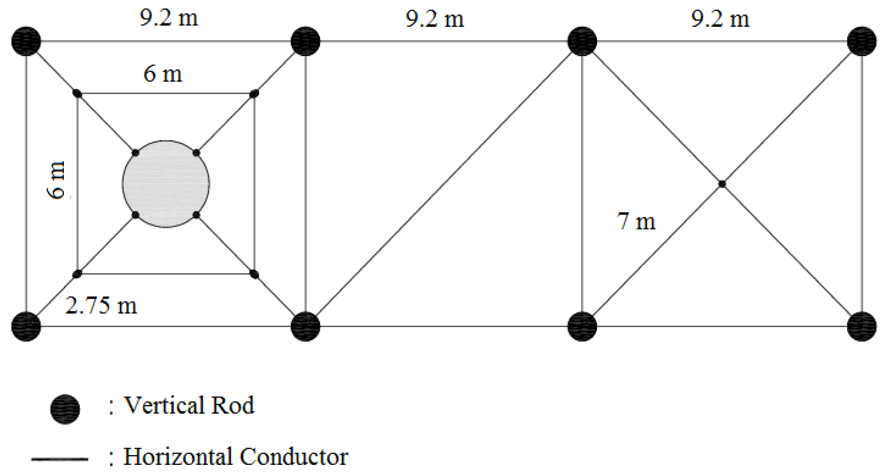
Typically, a grounding system consists of electrical conductors, ring electrodes, which are tied to the turbine tower around the wind turbine foundation to reach a specific resistance value by coupling vertical rods with them. However, this model fails to calculate the simultaneous impact of soil ionization and high frequency. This section presents a scheme that not only considers these two effects, but also noticeably reduces touch and step voltages.
The main factor behind this improvement is the addition of three additional electrodes and two rectangular rings, with the longer conductors connected to the local transformer grounding as shown in
Figure 1. Thanks to this new scheme, the need to repair and replace in the case of a fault occurrence is decreased. To examine the role of the PMGS, we assume that it is 1 m deep and further that the soil resistivity, relative permeability and permittivity are 100
m, 1 and 10, respectively.
In the following, the advantages obtained from the PMGS are explained through measuring the voltages of the wind turbine and the pair of turbines during lightning in diverse conditions.
4. Simulation Results and Discussion
This section examines the impact of the PMGS on the rate of overvoltages at the set-up (boost) transformers and control circuits in two diverse case studies, a single wind turbine and a pair of turbines. Based on the installation of several additional electrodes either at the local transformer or on the tower grounding side and adding two rings to increase the stability and reliability of grounding protection from the PMGS model (see
Figure 1), the influence of other high-frequency components such as high-frequency SA and FD cables are taken into account to arrive at a completely safe model for further transient studying.
Each turbine in a pair of turbines is equipped with a step-up transformer, which boosts the turbine generator output voltage from a few hundred volts to Medium Voltage (MV) distribution levels. These wind turbine step-up transformers are at a high risk of insulation, dielectrics stress and failure because they can cycle from low to high loads several times a day due to the nature of the wind turbine, which operates at continually changing power levels. As a result, the protection of such transformers is always a priority. Given this perspective, voltages at two different locations within the wind turbine are studied, on the LV side of the boost transformer and on the HV side from node to ground, to obtain the peak SA voltage. The other significant area that needs to be protected is the control system under nonlinear loads, as any damage or disruption to the control system would lead to down time in the operation of the single wind turbine and the pair of turbines [
42].
The peak value criteria for voltages are provided in the IEC standards. This study assumes that this amount is 2.5 kV for electrical equipment and 1.5 kV for electronic circuits such as LV control equipment.
4.1. Simulation Setup
The EMTP-RV software is suited for a wide variety of power system studies related to a project, its design or solving problems and unexplained failures. The software is capable of performing quick and effective simulations of giant power systems. In addition, its numerical robustness and the stability of the simulation engine make EMTP-RV a reliable reference for power system transient studies. For these reasons, this study uses the EMTPV-RV software to simulate the behavior of the PMGS in order to investigate its performance during a transient situation.
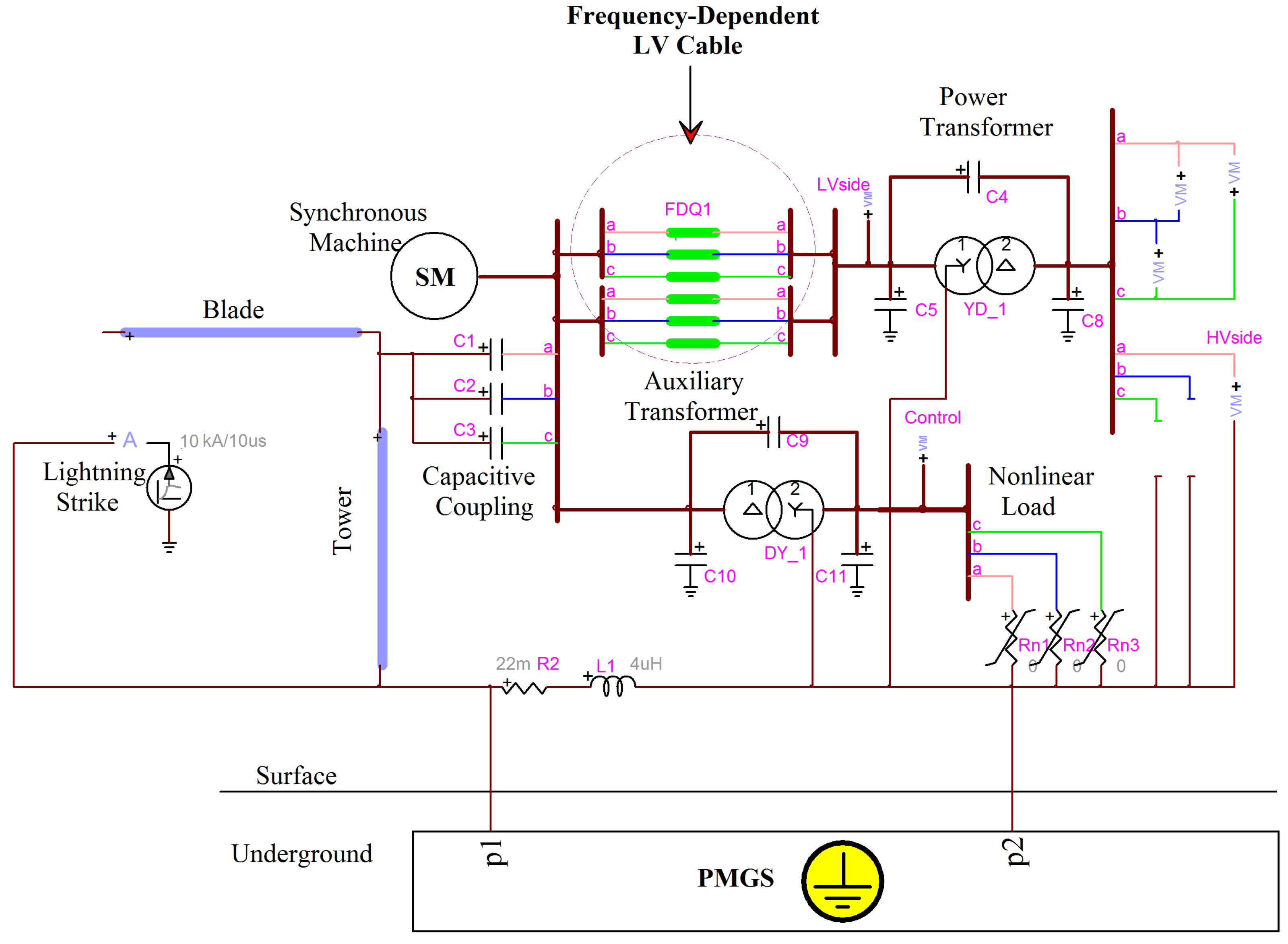
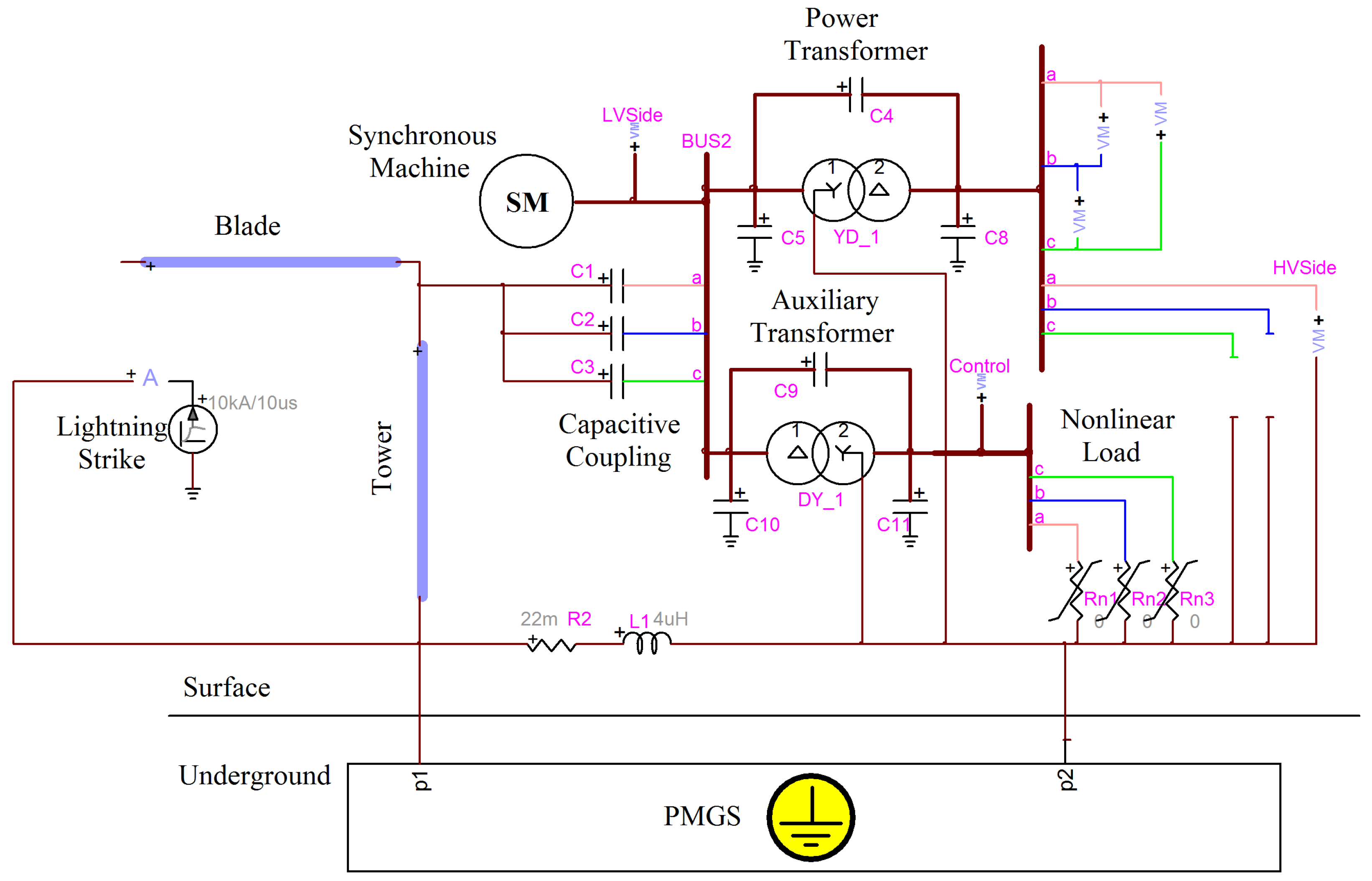
4.2. Single Wind Turbine
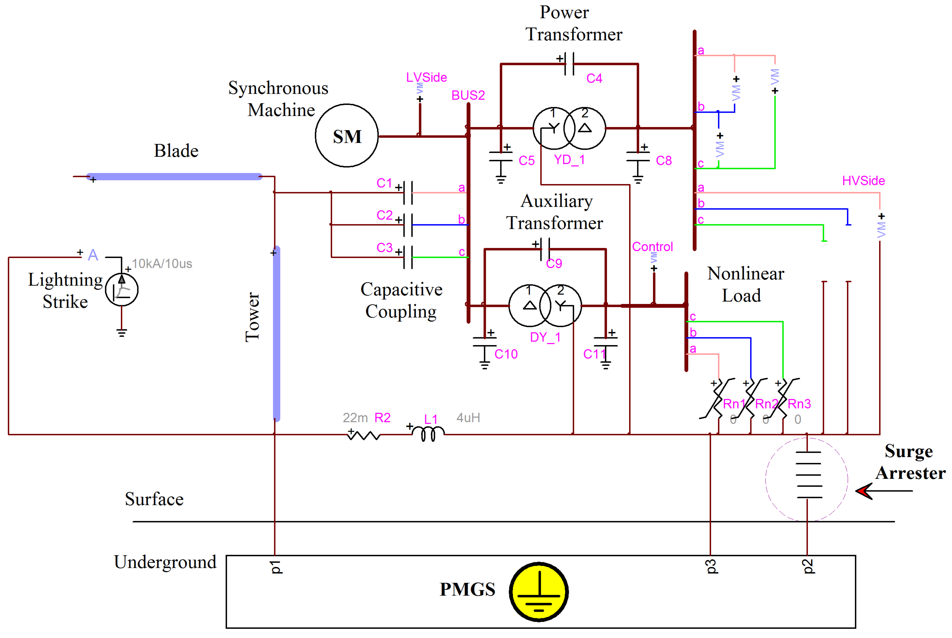
First, validation of the PMGS was investigated during indirect/direct strikes on a single wind turbine without any other protective devices. Next, the impact of other high-frequency parameters such as FD cable, electrode lengths, and SAs on the amounts of overvoltage was taken into account to achieve a complete model for further study. Finally, the comprehensive single wind turbine was used for an investigation of a direct strike.
The circuit diagram for the simulated single wind turbine with the PMGS is shown in
Figure 2.
4.2.1. Indirect Strike
The occurrence of indirect lightning strikes coming from the indirect effect of lightning discharges has recently received significant attention. This is due to the sensitive nature of the vital electronic equipment, which is highly vulnerable to such indirect effects. A study of the effect of indirect lightning on component voltage rates is presented next.
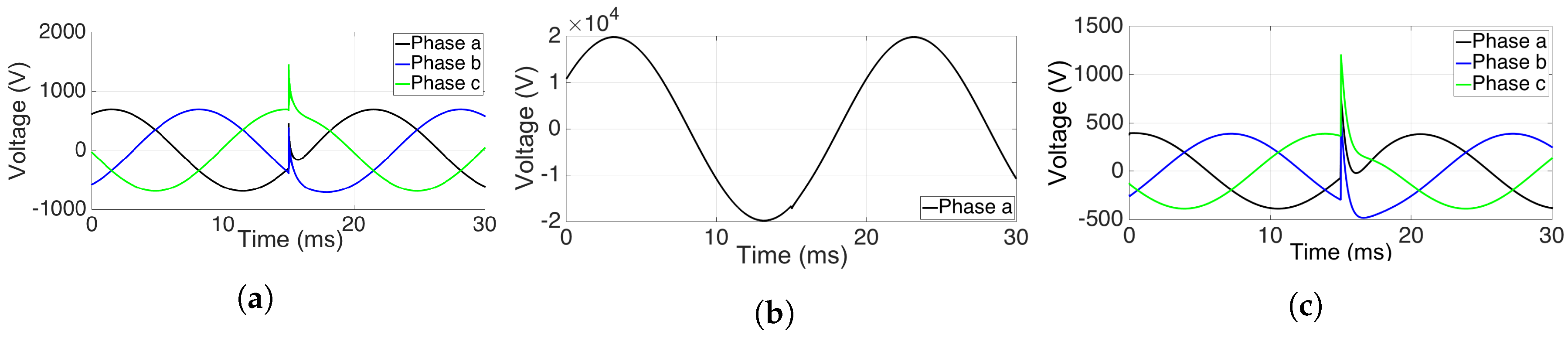
Impact of the PMGS on transient overvoltages: This case study assumes that lightning with a peak current value of 10 kA and a duration of 10/350
s strikes the ground near the tower. The maximum overvoltages reach nearly 1.5 kV for both the LV side and the control circuit, which shows that this strike can be tolerated by the wind turbine without failure. Additionally, this amount is negligible for the HV side (see
Figure 3).
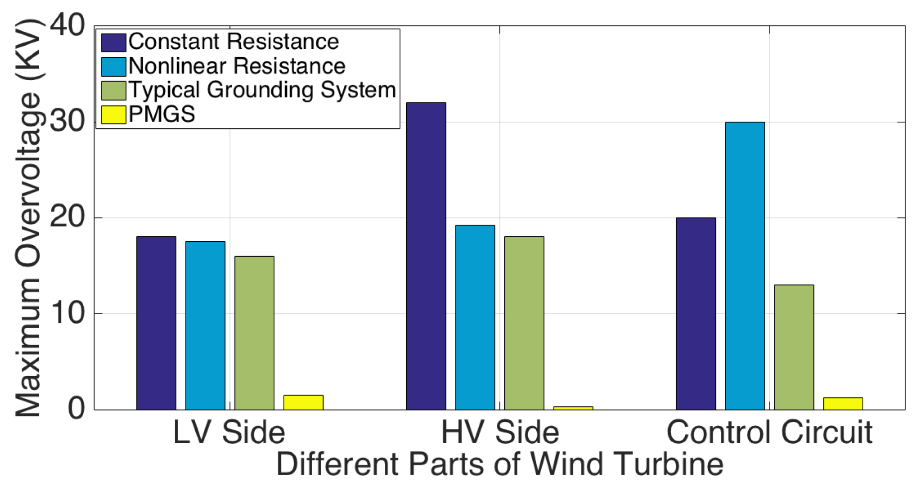
Figure 4 presents a comparison of previously-designed models (see
Section 2.6) and the PMGS. At first glance, it is clear that transient voltages in the constant resistance model have the highest values, so that in the worst condition, they escalate to 36 kV at the control circuit. Like constant resistance, nonlinear resistance did not considerably diminish the rate of overvoltage on the LV side; however, the peak value was reduced by
on the HV side and at the control circuit. Despite improving the grounding model over the typical expanded grounding system, nonlinear resistance was unable to limit the peak value to the level that can be withstood by wind turbine equipment. In the best condition, the peak value decreased to 13 kV at the control circuit, which is still higher than the upper limits. Finally, the PMGS seems to be successful in suppressing transient voltages that exceed upper limits, as the overvoltages reduce to 1.5 kV and 1.2 kV, respectively, on the LV side and at the control circuit. Moreover, the overvoltage is less than one hundred volts on the HV side, which is negligible.
Impact of high-frequency surge arrester on transient overvoltages: Although using the PMGS leads to a significant reduction in the maximum overvoltage, there is still a great need to install a high-frequency SA to protect a wind turbine against lightning. Therefore, in this subsection, a 1-kV high-frequency SA is added, as shown in
Figure 5, to verify its effect on the overvoltage.
The simulation indicates similar results for the PMGS as in the previous subsection (see
Section 4.2.1), and the high-frequency SA plays an important role in suppressing overvoltages and protecting the wind turbine from abnormal conditions (see
Figure 6). As a result, further study of the combination of the PMGS and high-frequency SAs can lead to powerful protection against lightning and the resulting transition states.
Impact of frequency-dependent cable on transient overvoltages: In this section, the FD cable model is added between the generator and the main transformer in order to see the effect of transient overvoltages beyond the PMGS effect (see
Figure 7).
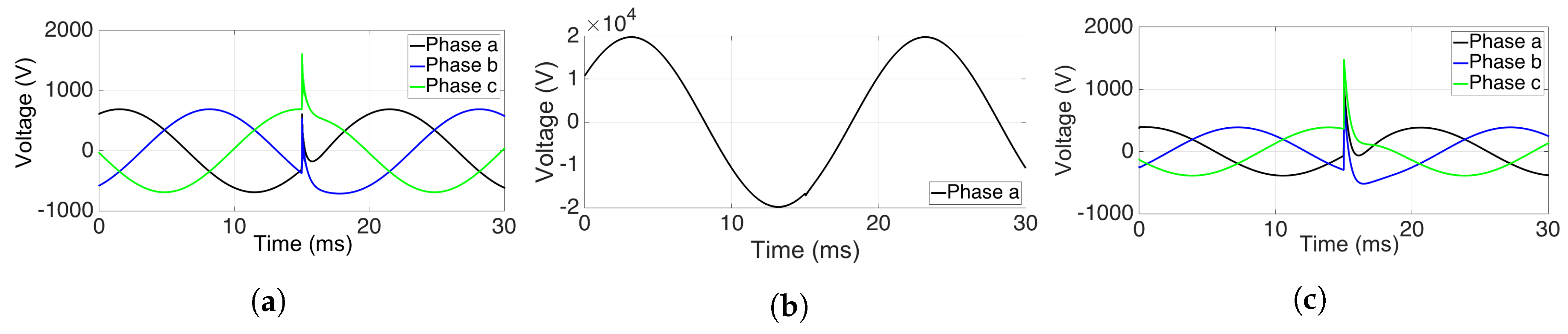
Figure 8 shows that the peak voltages are confined within the allowable limit, less than 1.5 kV, so it can be concluded that the FD cable behavior regarding voltage reduction is similar to how an SA and the PMGS behave toward limiting voltage and preventing extreme breakdowns. As a result, its vital role in the wind turbine protection model cannot be ignored, and it will be attached to the wind turbine system with the PMGS, in addition to adding a high-frequency SA, in subsequent sections.
Impact of increased horizontal conductor size on transient overvoltages: In this case, the horizontal electrodes of the PMGS are increased from their actual length, 9.2 m, to 15 m.
Figure 9 indicates that the maximum overvoltages on the LV side of the main power transformer (boost transformer) and the control equipment reach approximately 1 kV, which is in the normal range of the rated voltage. In this case, a nominal amount of overvoltage has again been obtained for the HV side. The outcomes establish that using the PMGS would be beneficial in rough areas with high soil resistivity that are difficult to dig.
Impact of increased vertical conductor size on transient overvoltages: In this subsection, the length of the electrical rods of the PMGS is increased from 3 m–4 m to see the probable changes in transient voltages. From
Figure 10, it can be seen that increasing the PMGS rod length does not by itself significantly change the transition behavior, since the maximum overvoltages are still around 1.5 kV for the LV side of the boost transformers and the control circuits, while this amount is so small for the HV side of the transformer that it can be ignored. Hence, it has been established that increasing the rod length cannot further improve the protection behavior.
Impact of comprehensive wind turbine model with the PMGS on transient overvoltages: The previous experiments show that to accomplish an effective model, it is necessary to integrate the PMGS with a high-frequency SA and FD cable. As has been shown regarding each of these devices, their consolidation can considerably reduce the number of transitions, as illustrated in
Figure 11.
Figure 12 shows that the peak voltage value for the LV side reaches 1 kV and for the control circuit reaches nearly 1.5 kV, both of which are below the upper limits the electrical devices can support and therefore ensure their safety. In addition, this value is less for the HV side and can therefore be neglected.
4.2.2. Direct Strike
This section analyzes the performance of the comprehensive wind turbine model with the PMGS when 10 kA and 10/350 s lightning directly hits the turbine and its blade in two different states. The first state, a so-called in-service wind turbine, is completely opposite from the second type, and all of the connections exist. The second state is an out-of-service wind turbine, in which not only is there no connection between the synchronous generator and the set-up transformer, but the grid is also disconnected.
In-service wind turbine: The rates of transient overvoltages during the direct strike are shown in
Figure 13. According to the simulation, this raised the voltage to 1.2 kV and approximately 1.5 kV on the LV side of the set up transformer and the control circuit, respectively, while it was just around zero for the HV side. The simulation establishes that in the in-service situation, the wind turbine can operate normally, as the greatest transitions still remain below the upper limits.
Out-of-service wind turbine: This subsection examines the impact of a direct lightning strike on the out-of-service wind turbine. The strike results in 1.2-kV peak voltages on the LV side of the main transformer, while the peak rises to 1.8 kV for the control equipment. The important fact is that the shape of the overvoltage on the HV side went up to 1.4 kV, compared to the negligible change when the lightning strikes the in-service turbine (see
Figure 14).
The main reason behind such an increased rate of voltage for the HV side and the SA is that the changes in the system configuration during the out-of-service state lead to alteration of the impedance characteristics. As a result, more lightning current passes through the earth and causes increased GPR, so the amount of voltage increases on the HV side through the absorbed SA energy. The consequence of such a phenomenon would be severe wind turbine failure. Hence, it seems to be crucial to separate the turbine generators from each other, the same as the transformers, to prevent burnout in the SA, transformers and cables when lightning directly hits the out-of-service tower.
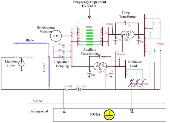
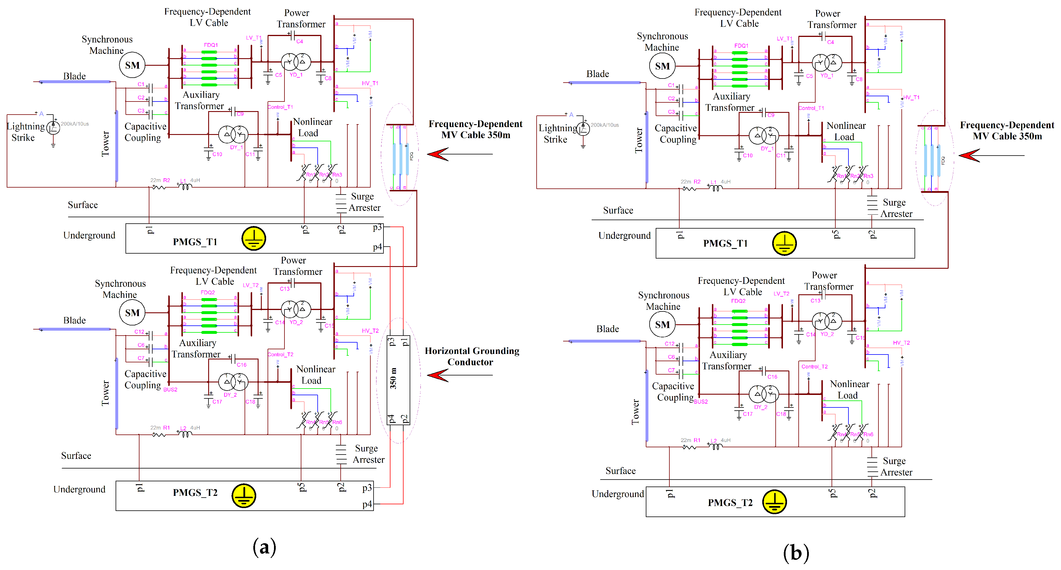
4.3. Pair of Turbines with Two Interconnected Turbines
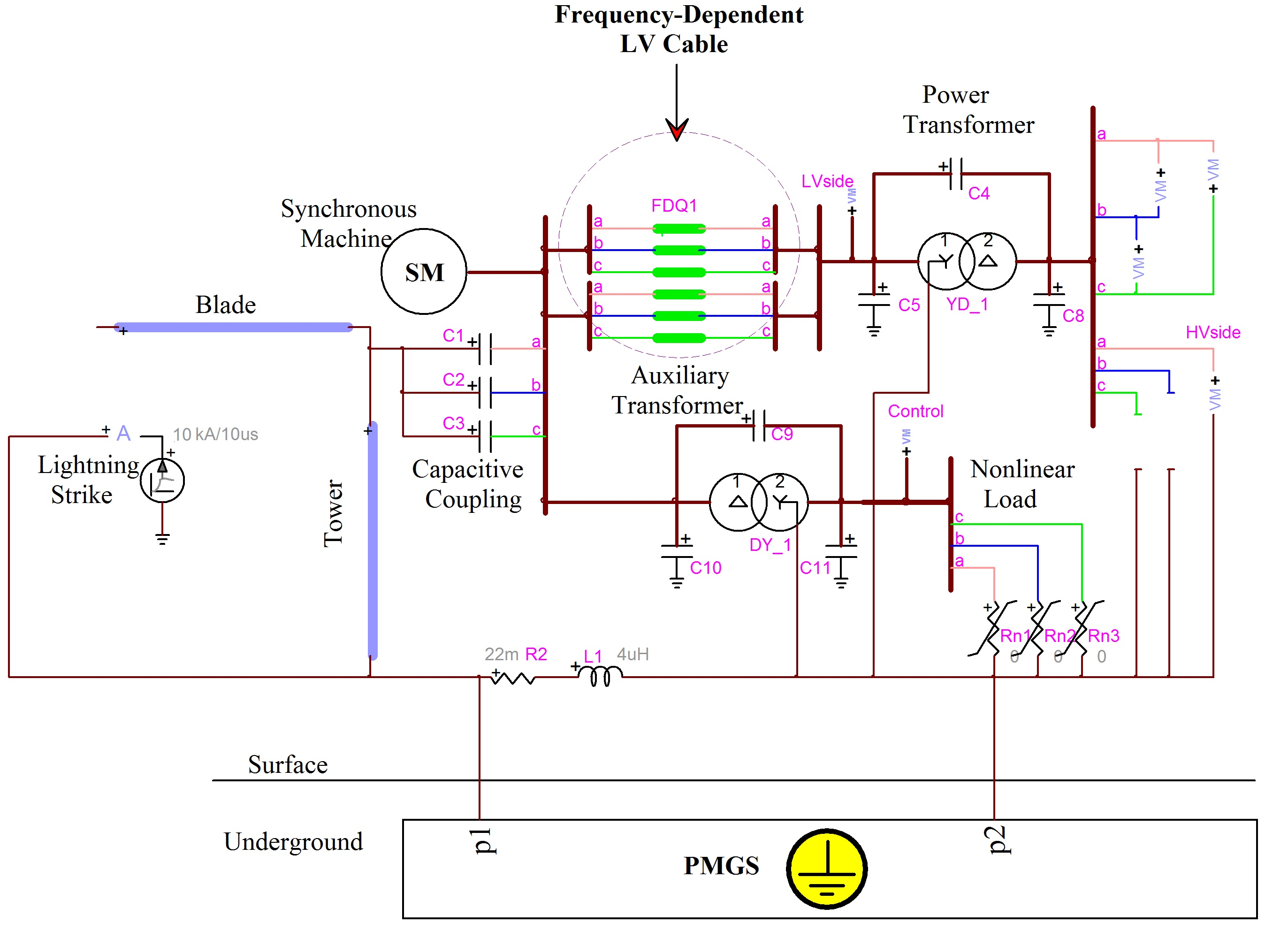
Since in reality, more than one wind turbine will be working to produce electricity, this study examines the impact of both indirect and direct lightning strikes on a pair of turbines that are connected to each other via a 350 m FD medium-voltage cable (see
Figure 15). The simulation was carried out for two states, one in which the turbines’ PMGSs are connected to each other through a 350-m horizontal grounding conductor, while in the other, the PMGSs are separated. Furthermore, they are compared in the worst lightning condition, not only to see the effect on overvoltages, but also to examine their performance in diverse strike conditions.
This section studies the impact of a 200-kA lightning strike, with the following results.
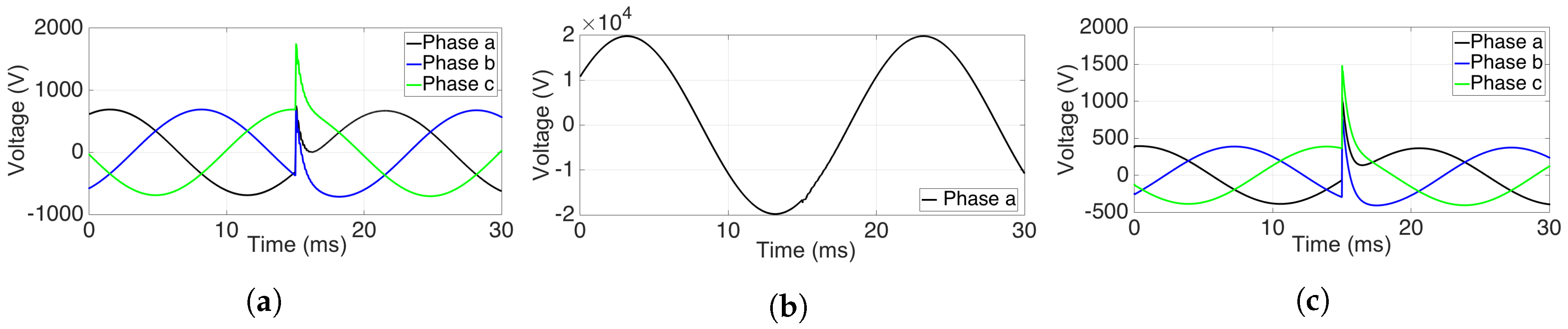
4.3.1. Impact of Indirect Lightning
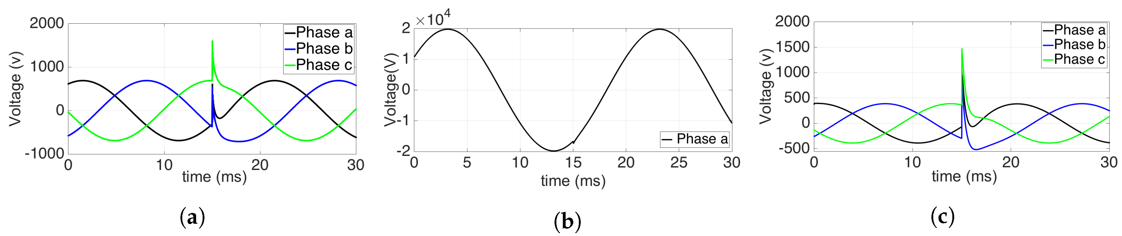
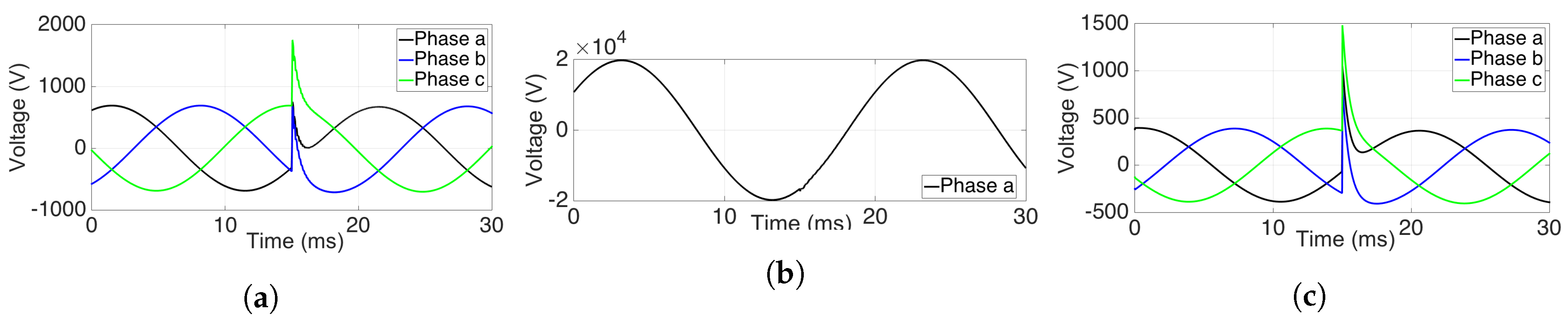
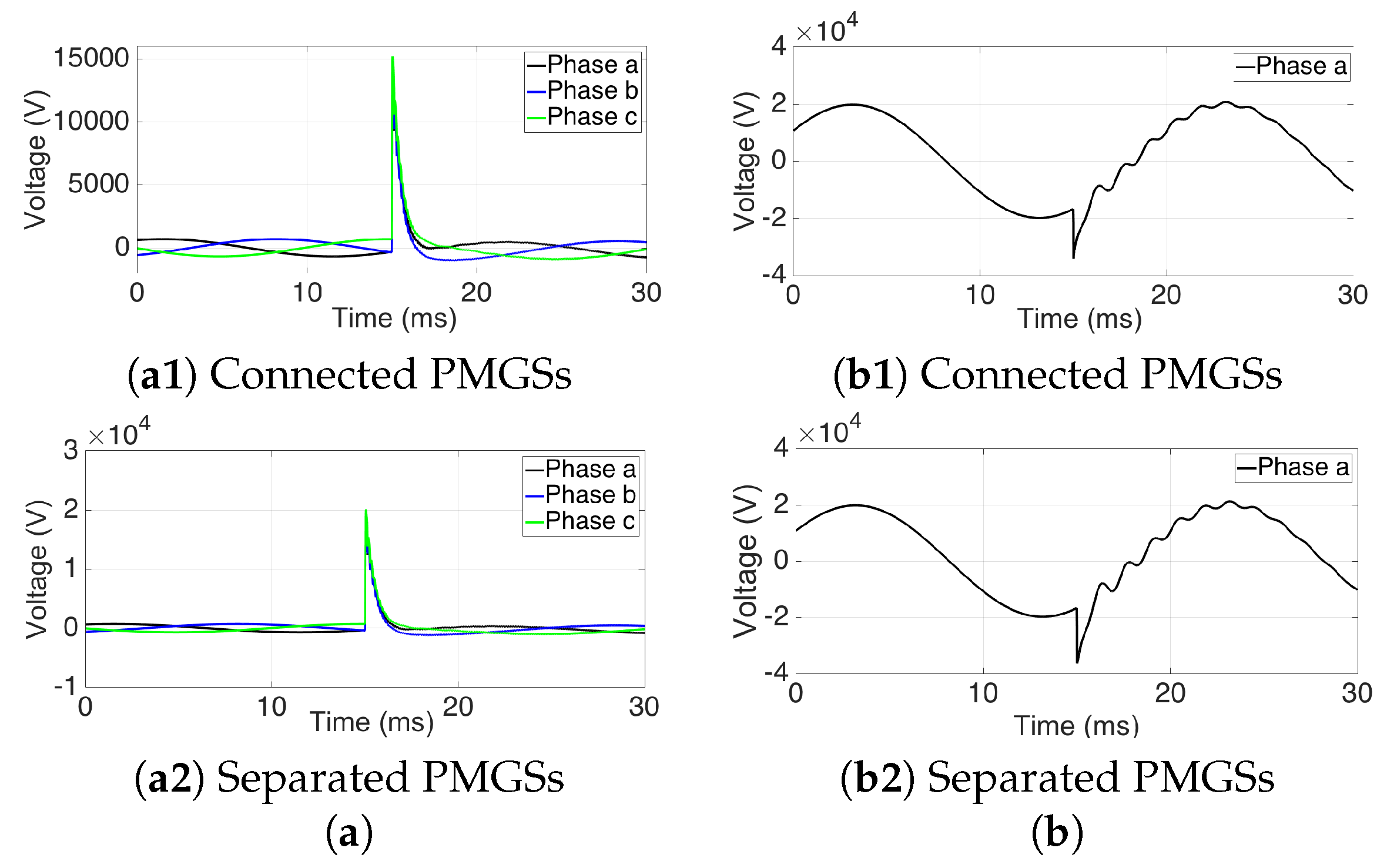
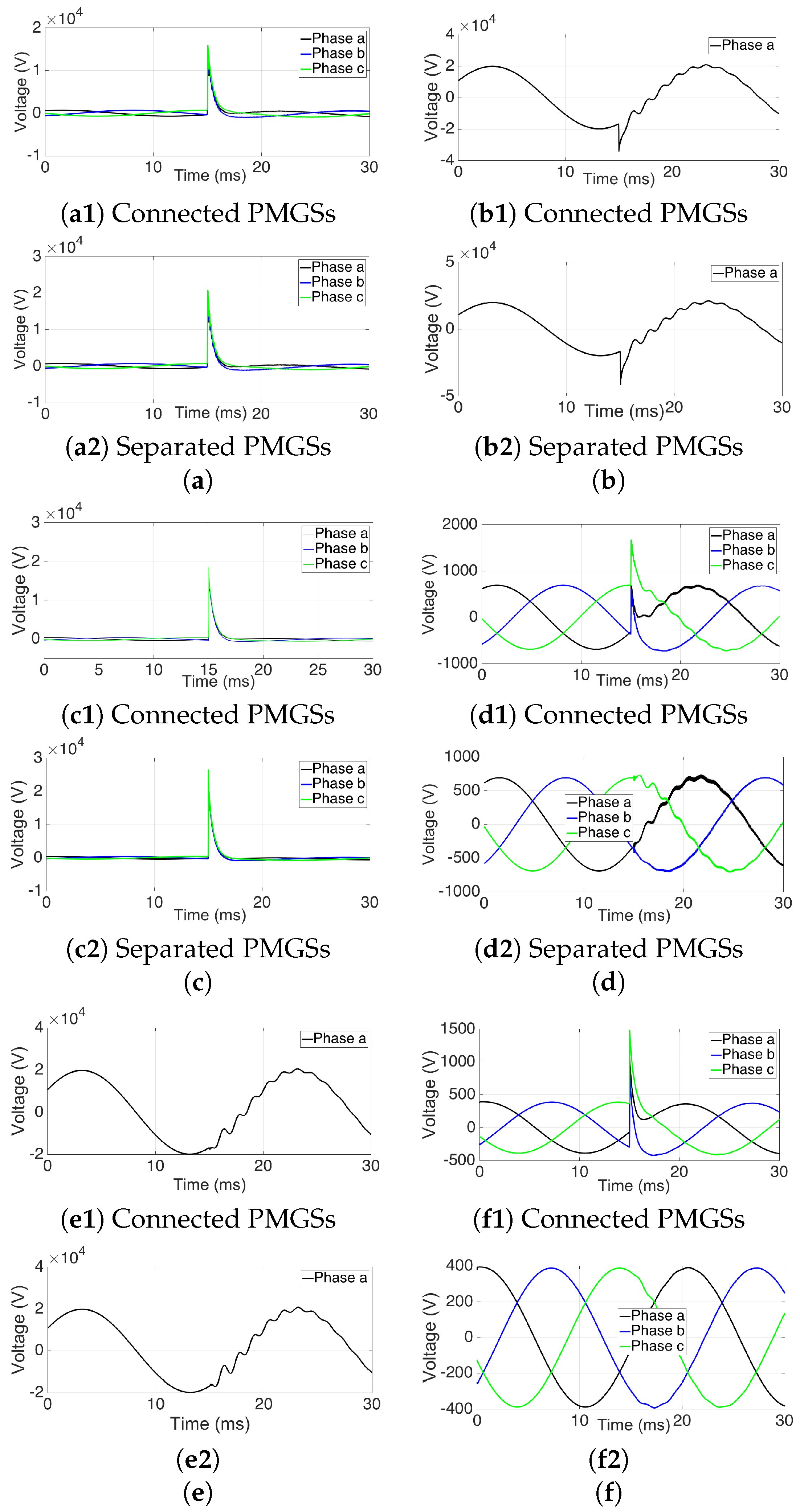
The peak value of the lightning current is assumed to be 200 kA with a duration of 10/350 s, the worst situation that a pair of turbines can experience. This subsection analyzes its impact on one of the towers when the strike hits the soil near the wind turbine. The outcomes show that the capability of integrated PMGSs to reduce the rate of overvoltages, even during the occurrence of harsh strikes with a peak value of 200 kA, is greater than the capabilities of separate PMGSs.
As
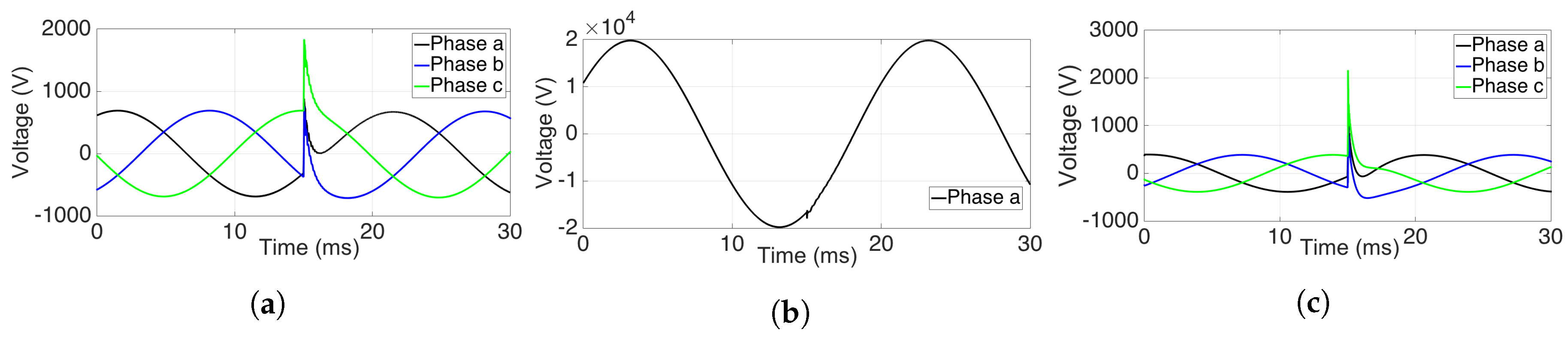
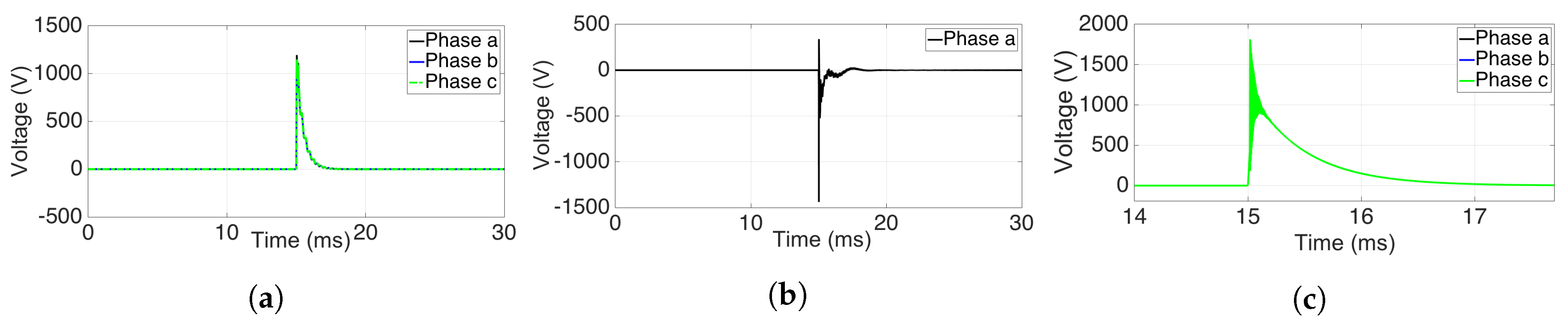
Figure 16a–c shows, even though connecting PMGSs in a pair of turbines can reduce the peak overvoltages from 60 kV–50 kV at the control system, from 75 kV–60 kV on the HV side and from 20 kV–14.5 kV on the LV side of the first wind turbine, they still remain much higher than the upper limits the electrical devices can withstand. However, in contrast to the first turbine, the second tower does not suffer from hazardous overvoltages and can bear such transitions without disruption (see
Figure 16d–f).
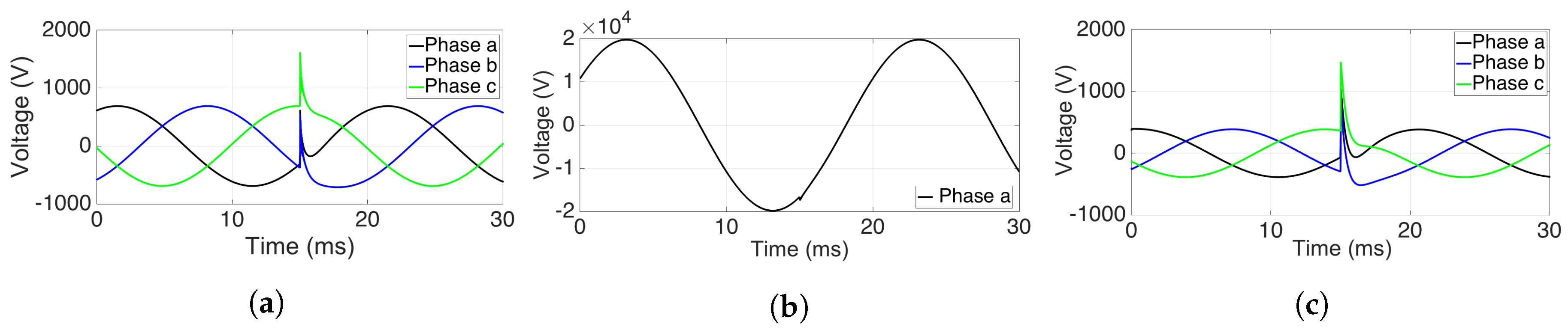
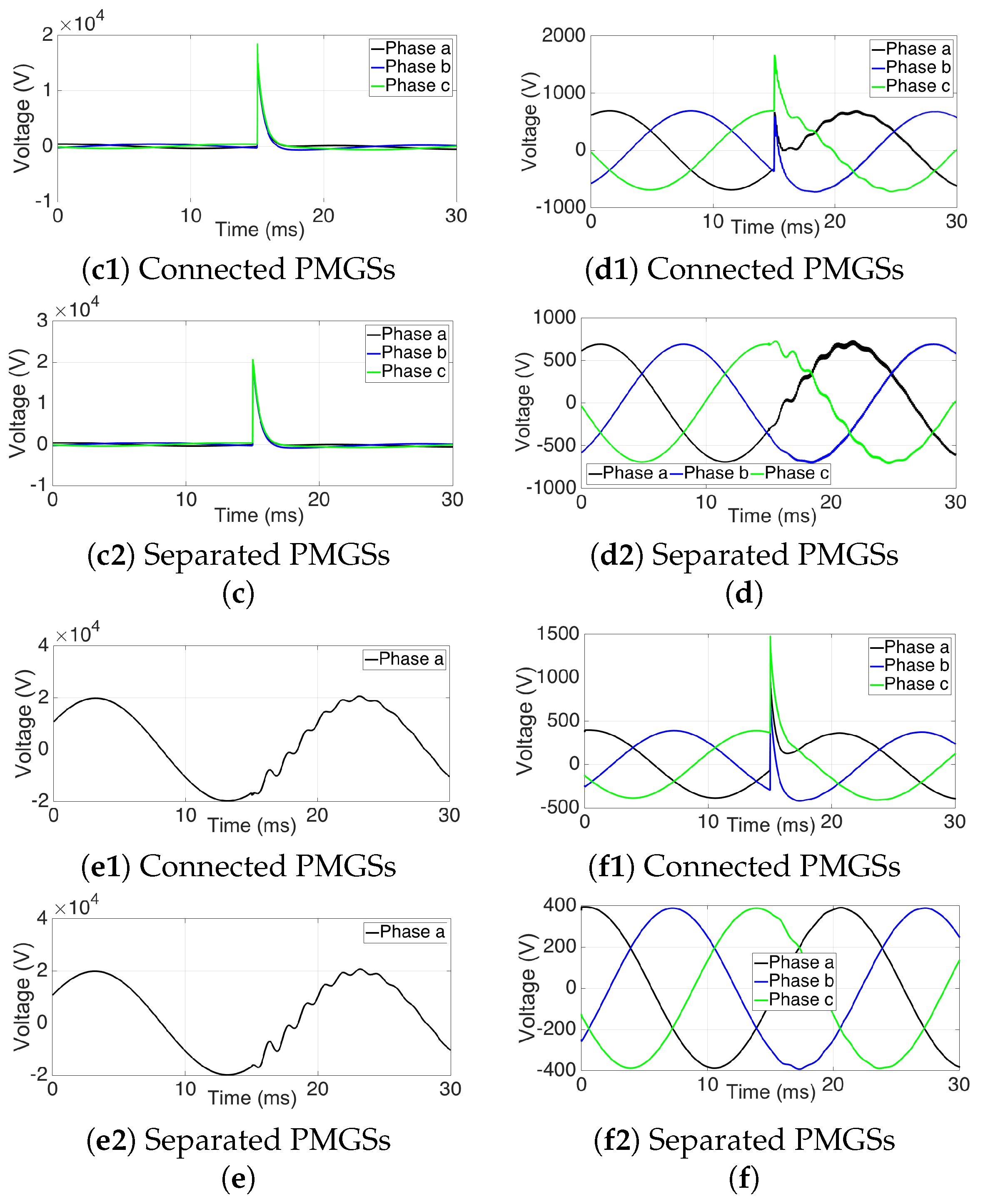
4.3.2. Impact of Direct Lightning
Figure 17a–c shows that despite reducing peak overvoltages from 26 kV–18 kV at the control equipment, from 40 kV–34 kV on the HV side and from 80 kV–78 kV on the LV side of the first wind turbine by connecting the PMGSs, the values are still above the upper limit and may lead to extreme failures. The situation for the second tower is completely different; in the worst condition, the peak value goes up to about 1 kV at the control system, which is within the normal range of the control circuit’s operation (
Figure 17d–f).
Even though the probability of a 200-kA lightning strike is scarce in nature, because of its devastating effect on sensitive electrical equipment, it is necessary to predict the transient voltage peaks in diverse conditions for wind turbine installations. The results are provided in
Table 1 and
Table 2.
The information shown in the tables indicates that despite the high overvoltages during lightning, the peak rates decrease by half in the PMGS model, which is indeed much more reasonable and safer for the wind turbines’ electric and electronic equipment compared to previous models (see
Section 2.6) and studies.


