Article

Fast Method of Recovering Reference-Wave Intensity in Two-Step-Only Quadrature Phase-Shifting Holography

1
Department of Precision Mechanical Engineering, Shanghai University, Shanghai 200072, China
2
Department of Electrical and Computer Engineering, Virginia Tech, Blacksburg, VA 24061, USA
*
Author to whom correspondence should be addressed.
Appl. Sci. 2017, 7(10), 1084; https://doi.org/10.3390/app7101084
Submission received: 10 August 2017 / Revised: 12 October 2017 / Accepted: 17 October 2017 / Published: 19 October 2017
(This article belongs to the Special Issue Holography and 3D Imaging: Tomorrows Ultimate Experience)

Abstract

:
We present a simple yet effective method, without the need for any additional recording of intensity maps or tremendous iterative computations, to recover reference-wave intensity resulting from the complex hologram acquired by quadrature phase-shifting holography. This is achieved by utilizing a certain area of interest in the complex hologram. We select a particular area in the complex hologram where there is negligible diffraction from the test sample to estimate the reference-wave intensity. The calculated intensity value allows us to extract exact phase distribution of the object in the context of two-step-only quadrature phase-shifting holography (TSO-PSH) without the zeroth-order beam and the twin image noise on the reconstruction plane. Computer simulation and experimental results have been performed to verify the effectiveness and feasibility of our proposed method.

1. Introduction

Digital holography (DH) is utilized for recording and reconstructing the intensity and phase of microstructures with high efficiency and precision, due to recent advances in charge-coupled devices (CCDs) and computers [1,2]. Indeed, digital holography has been widely employed in the applications of surface topography measurement, particle field analysis, and medical diagnosis during the past decades [3,4,5,6]. Zeroth-order beam and the twin image noise are the most important factors affecting the quality of the reconstructed object wavefront in DH. In optical holography, the off-axis geometry is an effective configuration for separating the zeroth-order beam and the twin image [7]. However, it is difficult to record a high-quality off-axis hologram in digital holography. When on-axis geometry is employed, we can eliminate the zeroth-order beam and twin-image noise with phase-shifting holography (PSH) [8,9]. Among the various techniques in PSH, two-step quadrature phase-shifting holography is one of the most widely used techniques by virtue of fewer recordings and easy operations as compared to other PSH techniques [10].
In order to eliminate the zeroth-order beam and twin-image noise, two phase-shifted holograms and one or two intensity images (namely, intensity images of both the object and the reference or one of them) are collected in two-step quadrature phase-shifting holography (QPSH). Xu et al. [11] have proposed an algorithm called two-step generalized phase-shifting interferometry, which still needs two intensity images. Meng et al. [12] have researched an algorithm using only two holograms and one intensity image, but the original complex object wave also needs to be recorded. Liu and Poon have studied a method called two-step-only quadrature phase-shifting holography (TSO-QPSH) [13], which estimates the reference intensity by iterative computations instead of an actual recording of the intensity map. Other researchers have optimized Liu and Poon’s algorithm to decrease the computational speed [14,15], but their proposed estimation methods are still relatively complex and computationally intensive.
Recently, we have proposed a very simple setup to calculate a complex hologram by using only two holograms with quadrature phase-shifting [16,17]. The constructed complex hologram contains the original information or its conjugate of the test object, which means the hologram can be reconstructed without the twin-image noise. However, the reconstructed image is not of good quality because the zeroth-order beam still exists on the reconstruction plane. Besides, all the investigations given above discuss the intensity reconstruction rather than the phase reconstruction of the object. The phase distribution of the test sample could not be retrieved precisely since there exists a complex zeroth-order term in the constructed complex hologram, giving rise to a zeroth-order beam upon reconstruction. In this contribution, we have focused on two-step phase shifting digital holography and proposed a fast method to recover the reference-wave intensity from the complex hologram without using either iteration procedure or physical measurement for exact phase retrieval. In the following sections, we describe our proposed method. Computer simulation and experimental results are then performed to verify the effectiveness and feasibility of our proposed idea.

2. Proposed Fast Method for Recovering Reference-Wave Intensity

In two-step quadrature phase-shifting holography, two phase-shifting on-axis holograms with a zero phase shift and a π/2 phase shift are achieved, as follows:
I I =   | R + O | 2 = I 0 + 2 R Re ( O ) ,
I Q =   | R e i π / 2 + O | 2 = I 0 + 2 R Im ( O ) ,
where O is the complex amplitude of the object wave on the recording plane, R is the reference wave on the recording plane, which is a plane wave and regarded as real amplitude for simplicity. I I is called the in-phase hologram and I Q is the quadrature hologram. I 0 is the bias or the background term in the hologram that is given by:
I 0 = R 2 + | O | 2 .
Upon optical illumination of hologram I I or I Q , I 0 gives rise to a zeroth-order beam that overlaps the reconstructed object beam on the reconstruction plane. Now, based on Equations (1) and (2), the complex amplitude of the object wave is found to be:
O = ( I I I 0 ) + i ( I Q I 0 ) 2 R .
After obtaining the complex amplitude of the object wave, we can perform backward propagation from the recording plane to the initial plane, and obtain the three-dimensional (3D) object distribution.
In order to extract the object wave, O , on the recording plane, the intensity of R and O should be recorded before holographic recordings as in traditional QPSH, as Guo and Devaney have done experimentally [10]. Liu and Poon have proposed a method called two-step-only quadrature phase-shifting holography (TSO-QPSH) to extract the object wave by estimating the reference-wave intensity using iterative computations instead of an actual recording of the intensity map. The iterative computation equation for the bias term, I 0 , is given by [13]:
I 0 = 2 R 2 + I I + I Q 2 ( 2 R 2 + I I + I Q ) 2 2 ( I I 2 + I Q 2 + 4 R 4 ) 2 .
In the above equation, I I and I Q are obtained experimentally and R 2 is obtained through iteration. Hence, Equation (4) is completely determined.
In our previous published paper [17], we have recorded two phase-shifted holograms and constructed a complex hologram given by:
I + i = I I + i I Q = ( 1 + i ) R 2 ( 1 + β ) + 2 R O ,
where β = |O|2/R2 is the intensity ratio of the object light and the reference light. Note that performing complex addition, as shown above, allows us to eliminate the twin image, O * . However, the zeroth-order term of the complex hologram still exists and is complex, being different from the two on-axis holograms in which the zeroth-order term is real and positive. So, if we want to obtain the exact phase information of the object, the complex zeroth-order term in the complex hologram needs to be removed. Equation (6) can be rewritten as:
I + i = I I + i I Q = A ( 1 + i ) + 2 R O ,
where A = R2(1 + β). Note that in this case, we have a complex bias term, A ( 1 + i ) , which gives rise to a zeroth-order beam upon reconstruction. To obtain also zeroth-order-beam-free reconstruction, we perform the following calculation:
I = I + i A ( 1 + i ) = 2 R O O .
Since I + i is known, the key factor is to find A . We propose a simple and yet effective method to estimate A . We select a particular area in the complex hologram where there is negligible diffraction on the CCD from the test sample to estimate A . We then adopt two criteria. First, we assume that the geometric projection of the sample onto the recording plane falls well within the boundaries of the CCD array. Hence, if the radius of the object is ω 0 , as a rule of thumb we set the following condition:
π ω 0 2 l × l ,
where l × l is the sensing square area of the CCD. Second, we assume r to be the diameter of the smallest detail of interest in the object. The distance from the object to the CCD is d , and λ is the light wavelength. We then stipulate that, according to far-field diffraction theory [2]:
λ r d l .
Under the above criteria, we see from the constructed complex hologram given by Equation (7) that the diffraction pattern of the object does not spread over all the hologram plane, and the complex zeroth-order term in the hologram, A ( 1 + i ) , essentially becomes the background, albeit being complex when we inspect the area of the hologram that is far away from the diffraction pattern on the recording plane. So, if we take the real part of this background, i.e., Re [ A ( 1 + i ) ], we have A . Once A is found, we use Equation (8) to extract the object wave. Note that, however, A = R2 (1 + β) is space-variant in general because β = |O|2/R2, with |O|2 being space-variant. Hence, in actuality, we should take an area of the background of the hologram and perform average locally over the area to better estimate the value of the reference-wave intensity, R2. Note that if β 1 , which is the case in the area of the complex hologram where the diffraction pattern of the sample is negligible, we have A = R2(1 + β) ~ R2, effectively finding the value of R2 using our scheme. In that case, we can use Equation (5) directly to find I 0 , and subsequently use Equation (4) to find O without the need for iteration to find R2, as with the technique proposed by Liu and Poon. Alternatively, once we have A from the above procedure, we put its value into Equation (8) to calculate O . We show simulations and experimental results by employing Equation (8) in the following section.

3. Results and Discussion

In this section, we present some results and discussion based on computer simulations and optical experiments to verify the effectiveness and feasibility of the proposed fast method.

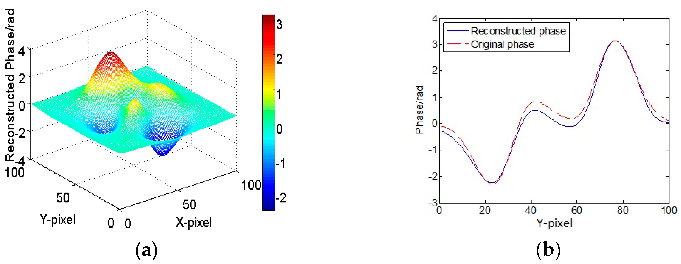
3.1. Computer Simulation Results

The simulated object is a phase object given by:
O ( x , y ) = exp [ i φ ( x , y ) ] ,
where φ ( x , y ) is the Peaks function in MATLAB. We set the maximum phase to be π radians. The three-dimensional phase distribution of the phase object is shown in Figure 1. The light wavelength λ is 632.8 nm, and the number of pixels in the recording CCD is 1024 × 1024, with each pixel size being 4.65 μm × 4.65 μm. The area of the object is 100 × 100 pixels, and the distance from the object plane to holographic recording plane, d, is 60 mm. All of the used parameters satisfy the sampling theorem, thereby avoiding aliasing issue [2]. We can successively construct the in-phase hologram, the quadrature hologram, and the complex hologram according to Reference [16] (see pp. 747–748 of the reference for details).
We first present the reconstructed phase result with the algorithm of two-step-only quadrature phase-shifting holography proposed by Liu and Poon in Figure 2. Figure 2b contains the line traces based on the original phase (red curve) from Figure 2a and the reconstructed phase (blue curve). Clearly, the result is effective and precise. However, the process for finding the reference-wave intensity, R2, is relatively complex, and the computation is intensive due to the required iteration process. We have also performed simulations using our proposed fast method to retrieve the phase. Here, we set both R and β to be 1, so A is equal to 2. The reconstructed results, according to Equation (8), are presented in Figure 3. Figure 3a shows the three-dimensional distribution of the retrieved phase. Figure 3b presents the line traces based on Figure 3a and the same section of the original phase. From Figure 3, we can easily see that the correct phase could be retrieved using our proposed method, but with some slight deviation. That is because term A is in general space-variant and is not equal to a constant. In the actual experimental work, A should be found by averaging over its neighborhood to gain a better estimate of R2. Comparing Figure 2 with Figure 3, Liu and Poon’s method gives a better result, but the computation is intensive. On the other hand, the reconstructed phase using our proposed method is fast and satisfactory upon most occasions. It would be practically useful in some cases where the spatial bandwidth of objects is lower than that of the holographic system.

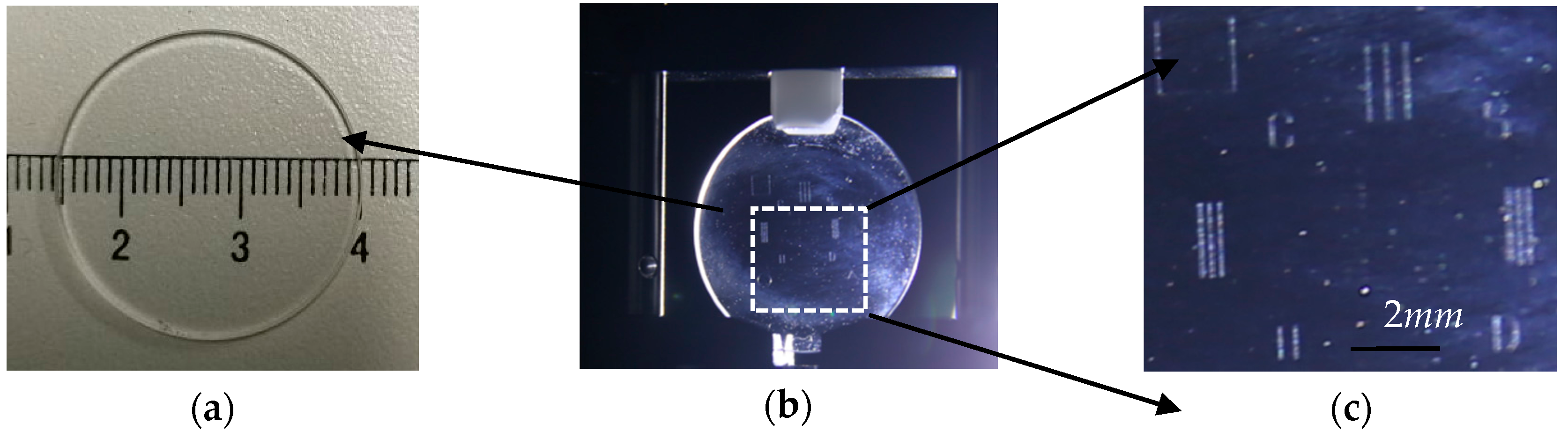
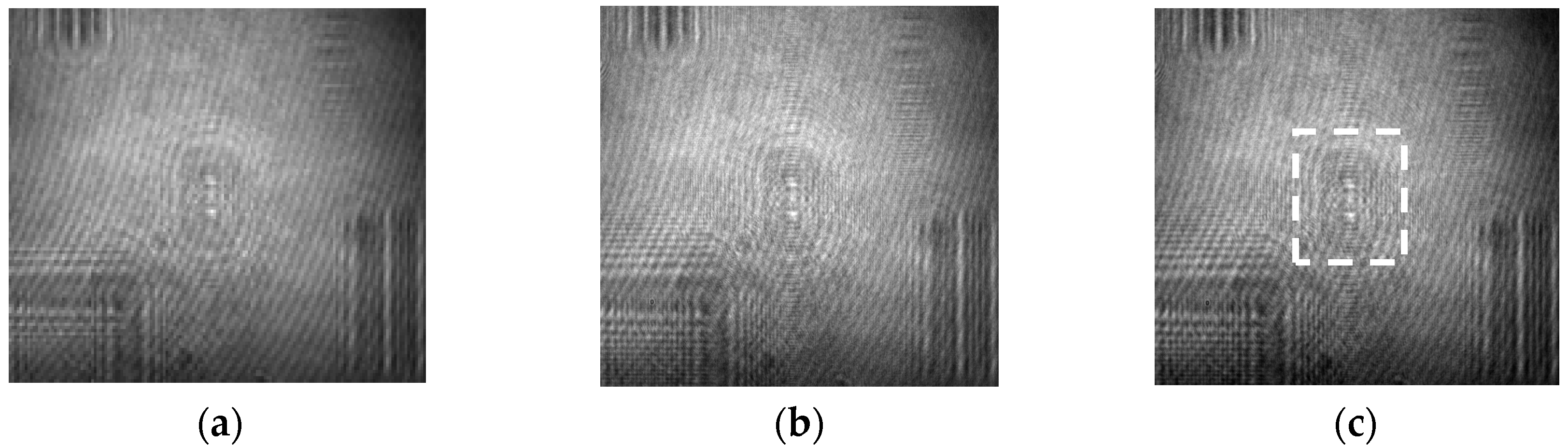
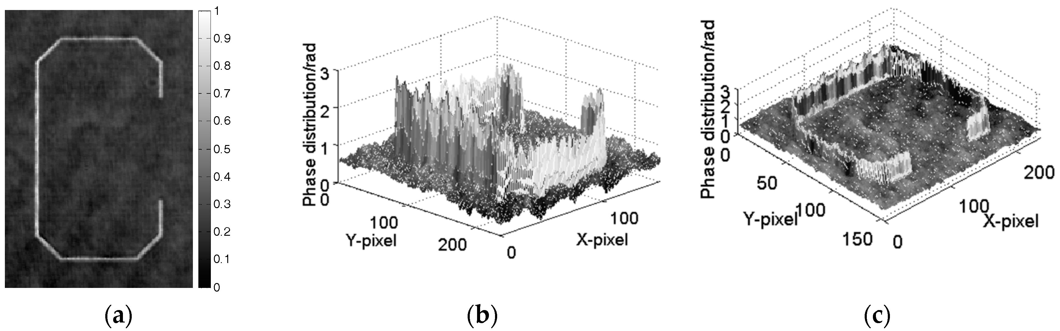
3.2. Optical Experimental Results

A Mach-Zehnder interference system is set up as shown in Figure 4. The laser light goes through a spatial filter and a collimator to form planar wavefronts. Then, the plane wave is divided into two beams by beam splitter 2. One of the beams illuminates test sample 6 to produce object wavefront. Another one is taken as the reference wavefront through optical flat glass plate 4. The two wavefronts interfere with each other on the recording plane to form an in-line hologram (in-phase-hologram), which can be recorded by CCD camera 8. The wavelength of He-Ne Laser is 632.8 nm, and the size of the captured holograms is 960 × 1280 pixels with each pixel size of 4.65 μm, giving l 4.6   mm for 1000 pixels. Optical flat glass plate 4 is a phase-shifting element. The change of the phase of the reference can be achieved by rotating the optical flat glass plate to obtain the quadrature hologram. The method to carry out π/2 phase-shifting and calibration is detailed in the literature [17] (see pp. 1565–1566 of the literature). The recording distance is d = 75.6   mm .
We have performed optical experiments to explain the influence of the zeroth-order term in the complex hologram for phase retrieval and to verify the effectiveness of our proposed method in recovering the reference-wave intensity. The test sample is a capital letter “C” engraved on a round piece of glass plate, shown in Figure 5. The diameter of the round glass plate is 25 mm, and the size of the letter “C” is about 1.4 mm × 0.8 mm, i.e., ω 0 0.7   mm , with a line width of r 0.047   mm . All parameters used in the experiment satisfy the criteria established in Equations (9) and (10).
In Figure 6a–c, we present the captured in-phase hologram, I I , the quadrature hologram, I Q , and the intensity of the complex hologram I + i as constructed by Equation (6).
We have reconstructed the part of the complex hologram enclosed by the white dotted rectangular area in Figure 6c. Results are shown in Figure 7. Figure 7a presents the two-dimensional phase map in grayscale, and Figure 7b,c show the three-dimensional phase distribution corresponding to the different views. It is obvious that the retrieved phase is contaminated by the existence of the zeroth-order beam due to the bias term or the zeroth-order term, A ( 1 + i ) , in Equation (7).
To recover the reference-wave intensity from the complex hologram, we have estimated A by selecting certain area (we used a 3 × 3 matrix to find A ) far away from the diffraction pattern of the letter “C” in the complex hologram where negligible diffraction of the letter “C” has occurred. Once A has been found, we performed the calculation based on Equation (8) to find the complex object wave. Subsequently, we numerically propagate the object wave to obtain the phase distribution of the object. The final results are presented in Figure 8, which confirm the effectiveness of the method proposed by comparing with the results shown in Figure 7. Strictly speaking, the reconstructions shown in Figure 8 are twin-image–free and reference intensity-free. Only when β 1 do we have an approximate twin-image free and zeroth-order-beam free reconstruction.

4. Conclusions

This paper presents a novel method to recover the reference-wave intensity for two-step-only quadrature phase-shifting holography, which is much simpler and faster than the previous methods reported. The reference-wave intensity can be obtained through selecting a particular area within the complex hologram with negligible diffraction of the test sample. Once the reference-wave intensity is obtained, we can use Equations (4) and (5) to extract the exact phase distribution of the object without the twin-image noise and zeroth-order beam on the reconstruction plane. Alternatively, phase distribution can be reconstructed approximately by using the new complex hologram without the reference-wave intensity and twin image noise based on Equation (8). Both our simulation and experimental results have demonstrated the feasibility of our proposed method. This method can be carried out without any additional recording of the intensity map and iterative computations, and its simplicity and effectiveness may be useful in QPSH and other related fields. Finally, we want to point out that for β = | O | 2 / | R | 2 1 , i.e., when the intensity of the object light is much less than that of the reference light, Equation (8) would give an approximate twin-image-free and zeroth-order-beam-free reconstruction and this aspect is worthy of further investigation.

Acknowledgments

Portions of this work were presented at the Conference on Three-Dimensional Image Acquisition and Display Technology 2016 (3DIADT2016), Jinhua, China. Wen-Jing Zhou et al., Phase Retrieval in Two-Step Quadrature Phase-Shifting Holography, Proc. of SPIE 2017 Vol. 10255, pp.1025501-1 to 1025501-7.

Author Contributions

Ting-Chung Poon and Wen-Jing Zhou conceived and designed the experiments; Wen-Jing Zhou and Caifu Zheng performed the experiments; Ting-Chung Poon, Wen-Jing Zhou, and Caifu Zheng analyzed the data; Wen-Jing Zhou contributed analysis tools; Wen-Jing Zhou and Caifu Zheng wrote the paper; Ting-Chung Poon revised the paper.

Conflicts of Interest

The authors declare no conflict of interest.

References

  1. Schnars, U.; Jüptner, W. Digital recording and numerical reconstruction of holograms. Meas. Sci. Technol. 2002, 13, 85–101. [Google Scholar] [CrossRef]
  2. Poon, T.-C.; Liu, J.-P. Introduction to Modern Digital Holography with MATLAB; Cambridge University Press: Cambridge, UK, 2014. [Google Scholar]
  3. Seebacher, S.; Osten, W.; Baumbach, T.; Jüptner, W. The determination of material parameters of microcomponents using digital holography. Opt. Lasers Eng. 2001, 36, 103–126. [Google Scholar] [CrossRef]
  4. Katz, J.; Sheng, J. Applications of holography in fluid mechanics and particle dynamics. Annu. Rev. Fluid Mech. 2010, 42, 531–555. [Google Scholar] [CrossRef]
  5. Wahba, H.H. Reconstruction of 3D refractive index profiles of PM PANDA optical fiber using digital holographic method. Opt. Fiber Technol. 2014, 20, 520–526. [Google Scholar] [CrossRef]
  6. Osten, W.; Faridian, A.; Gao, P.; Korner, K.; Naik, D.; Pedrini, G.; Singh, A.K.; Takeda, M.; Wilke, M. Recent advances in digital holography. Appl. Opt. 2014, 53, 44–63. [Google Scholar] [CrossRef] [PubMed]
  7. Leith, E.N.; Upatnieks, J. Reconstructed wavefronts and communication theory. J. Opt. Soc. Am. 1962, 52, 1123–1130. [Google Scholar] [CrossRef]
  8. Yamaguchi, I.; Kato, J.-I.; Ohta, S.; Mizuno, J. Image formation in phase-shifting digital holography and applications to microscopy. Appl. Opt. 2001, 40, 6177–6186. [Google Scholar] [CrossRef] [PubMed]
  9. Liu, J.-P.; Poon, T.-C.; Jhou, G.S.; Chen, P.J. Comparison of two-, three-, and four-exposure quadrature phase-shifting holography. Appl. Opt. 2011, 50, 2443–2450. [Google Scholar] [CrossRef] [PubMed]
  10. Guo, P.; Devaney, A.J. Digital microscopy using phase-shifting digital holography with two reference waves. Opt. Lett. 2004, 29, 857–859. [Google Scholar] [CrossRef] [PubMed]
  11. Xu, X.F.; Cai, L.Z.; Wang, Y.R.; Yan, R.S. Direct phase shift extraction and wavefront reconstruction in two-step generalized phase-shifting interferometry. J. Opt. 2010, 12, 74–77. [Google Scholar] [CrossRef]
  12. Meng, X.F.; Cai, L.Z.; Xu, X.F.; Yang, X.L.; Shen, X.X.; Dong, G.Y.; Wang, Y.R. Two-step phase-shifting interferometry and its application in image encryption. Opt. Lett. 2006, 31, 1414–1416. [Google Scholar] [CrossRef] [PubMed]
  13. Liu, J.-P.; Poon, T.-C. Two-step-only quadrature phase-shifting digital holography. Opt. Lett. 2009, 34, 250–252. [Google Scholar] [CrossRef] [PubMed]
  14. Zhang, S.Q.; Zhou, J.Y. A new estimation method for two-step-only quadrature phase-shifting digital holography. Opt. Commun. 2015, 335, 183–188. [Google Scholar] [CrossRef]
  15. Chen, B.X.; Tian, Y.Z.; Zhao, N.N.; Wang, L.; Chen, D.X.; Liang, E.J. Optimization of two-step phase-shifting digital hologram algorithm and experimental verification. Laser Optoelectron. Prog. 2015, 52, 138–142. (In Chinese) [Google Scholar]
  16. Zhou, W.-J.; Yang, X.; Poon, T.-C. Reconstructing of two combined on-axis holograms with π/2-phase difference. In Proceedings of the IEEE 13th International Conference on Industrial Informatics, Cambridge, UK, 22–24 July 2015; IEEE: Cambridge, UK, 2015; pp. 746–749. [Google Scholar]
  17. Zhou, W.-J.; Zhang, H.B.; Yu, Y.J.; Poon, T.-C. Experiments on a simple setup for two-step quadrature phase shifting holography. IEEE Trans. Ind. Inform. 2016, 12, 1564–1570. [Google Scholar] [CrossRef]
  18. Zhou, W.-J.; Zheng, C.F.; Zhang, H.B.; Yu, Y.J.; Poon, T.-C. Phase retrieval in two-step quadrature phase-shifting holography. Proc. SPIE 2017, 10255, 1025501. [Google Scholar] [CrossRef]
Figure 1. Original phase distribution φ ( x , y ) , where φ ( x , y ) is the Peaks function in MATLAB (a) Three-dimensional (3D) phase distribution; (b) Phase line trace along Y at X-pixel = 50 on Figure 1a.
Applsci 07 01084 g001
Figure 2. Reconstructed phase using Liu and Poon’s method. (a) 3D reconstructed phase distribution; (b) Phase line trace along Y at X-pixel = 50 on Figure 2a and the same section of the original phase.
Applsci 07 01084 g002
Figure 3. Reconstructed phase using our proposed method. (a) 3D reconstructed phase distribution; (b) Phase line trace along Y at X-pixel = 50 on Figure 3a (blue curve) and the same section of the original phase (red curve).
Applsci 07 01084 g003
Figure 4. System setup of two-step quadrature phase-shifting holography (QPSH). (a) Experimental optical system; (b) Schematic illustration of Figure 3a: 1 = He-Ne laser and collimator, 2, 7 = Beam splitter, 3, 5 = Reflective mirror, 4 = Optical flat glass plate, 6 = Test sample, 8 = charge-coupled device (CCD), 9 = Computer.
Applsci 07 01084 g004
Figure 5. A letter “C” engraved on the glass plate as test sample. (a) Dimension figure for glass plate; (b) Test sample on system setup; (c) Partial enlarged view of Figure 5b. The letter ‘C” is seen on the second quadrant of the figure. After Reference [18].
Applsci 07 01084 g005
Figure 6. Two phase-shifting holograms and constructed hologram in recording plane. (a) In-phase hologram I I ; (b) Quadrature hologram I Q ; (c) Magnitude of Complex hologram I + i . After Reference [18].
Applsci 07 01084 g006
Figure 7. Phase retrieval results with zeroth-order term still existing. (a) Retrieved phase map in grayscale with zeroth-order term; (b) Left view of 3D reconstructed phase distribution; (c) Right view of 3D reconstructed phase distribution.
Applsci 07 01084 g007
Figure 8. Phase retrieval results according to Equation (8) with A found with the proposed technique. (a) Retrieved phase map in grayscale; (b) Left view of 3D reconstructed phase distribution; (c) Right view of 3D reconstructed phase distribution. Adapted from Reference [18].
Applsci 07 01084 g008

