Article

Artificial-Crack-Behavior Test Evaluation of the Water-Leakage Repair Materials Used for the Repair of Water-Leakage Cracks in Concrete Structures

1
Institute of Biomedical Engineering and Biomaterials Program of Architecture, Seoul National University of Science & Technology, 232 Gongneung-ro, Nowon-gu, Seoul 01811, Korea
2
School of Architecture, Seoul National University of Science & Technology, 232 Gongneung-ro, Nowon-gu, Seoul 01811, Korea
*
Author to whom correspondence should be addressed.
Appl. Sci. 2016, 6(9), 253; https://doi.org/10.3390/app6090253
Submission received: 1 August 2016 / Revised: 30 August 2016 / Accepted: 31 August 2016 / Published: 9 September 2016
(This article belongs to the Section Materials Science and Engineering)

Abstract

:
There are no existing standard test methods at home and abroad that can verify the performance of water leakage repair materials, and it is thus very difficult to perform quality control checks in the field of water leakage repair. This study determined that the key factors that have the greatest impact on the water leakage repair materials are the micro-behaviors of cracks, and proposed an artificial-crack-behavior test method for the performance verification of the repair materials. The performance of the 15 kinds of repair materials that are currently being used in the field of water leakage repair was evaluated by applying the proposed test method. The main aim of such a test method is to determine if there is water leakage by injecting water leakage repair materials into a crack behavior test specimen with an artificial 5-mm crack width, applying a 2.5 mm vertical behavior load at 100 cycles, and applying 0.3 N/mm2 constant water pressure. The test results showed that of the 15 kinds of repair materials, only two effectively sealed the crack and thus stopped the water leakage. The findings of this study confirmed the effectiveness of the proposed artificial-crack-behavior test method and suggest that it can be used as a performance verification method for checking the responsiveness of the repair materials being used in the field of water leakage repair to the repetitive water leakage behaviors that occur in concrete structures. The study findings further suggest that the use of the proposed test method makes it possible to quantify the water leakage repair quality control in the field.

1. Introduction

The cracks that are present in underground concrete structures are continuously subjected to contraction/expansion [1] due to the temperature and humidity changes that occur, the “micro-behaviors” [2] caused by differential settlement, the water pressure, the vehicle vibration, and the environmental effects resulting from the water quality (chemical components), flow rate, and constantly wet condition [3].
The typical micro-behaviors that cracks are subjected to can be divided into the physical behaviors caused by vehicle operation, cargo storage and movement, human traffic, equipment vibration, earthquakes [4] and settlement, and behaviors due to climate impacts, such as wind, humidity, and temperature changes. In particular, underground concrete structures are also influenced by the micro-behaviors caused by the earth pressure, water pressure, and flow rate due to the constant groundwater flow [5,6,7,8]. This behavioral impact has an adverse effect on the performance of the water leakage repair materials, resulting in long-term water tightness performance (durability) degradation.
As cracks bring about not only structural safety problems but also water leakage problems, the materials and methods used for the repair of such cracks should be able to respond to the cracks’ micro-behaviors [9]. Various materials and methods have been used for the repair of structural cracks in many countries [10], but there are no existing quality control standards that reflect the complex environmental conditions of an underground space, or test methods for evaluating such conditions, which leads to the frequent re-leakage of water resulting from crack repair failures [11,12]. In particular, the repeated repair works due to the re-leakage of water have posed a social problem, causing a decrease in the safety level of structures, an increase in the maintenance costs, and user anxiety and discomfort, among others.
As such, this study selected the micro-behaviors of cracks as the factors that have the greatest impact on the performance of water leakage repair materials, and proposed a performance evaluation test method for such materials. In addition, this study sought to verify the performance of the repair materials that are currently being used in the field of water leakage repair by applying the proposed test method, and to thus quantify the quality control of water leakage repair.

2. Artificial-Crack-Behavior Test Method
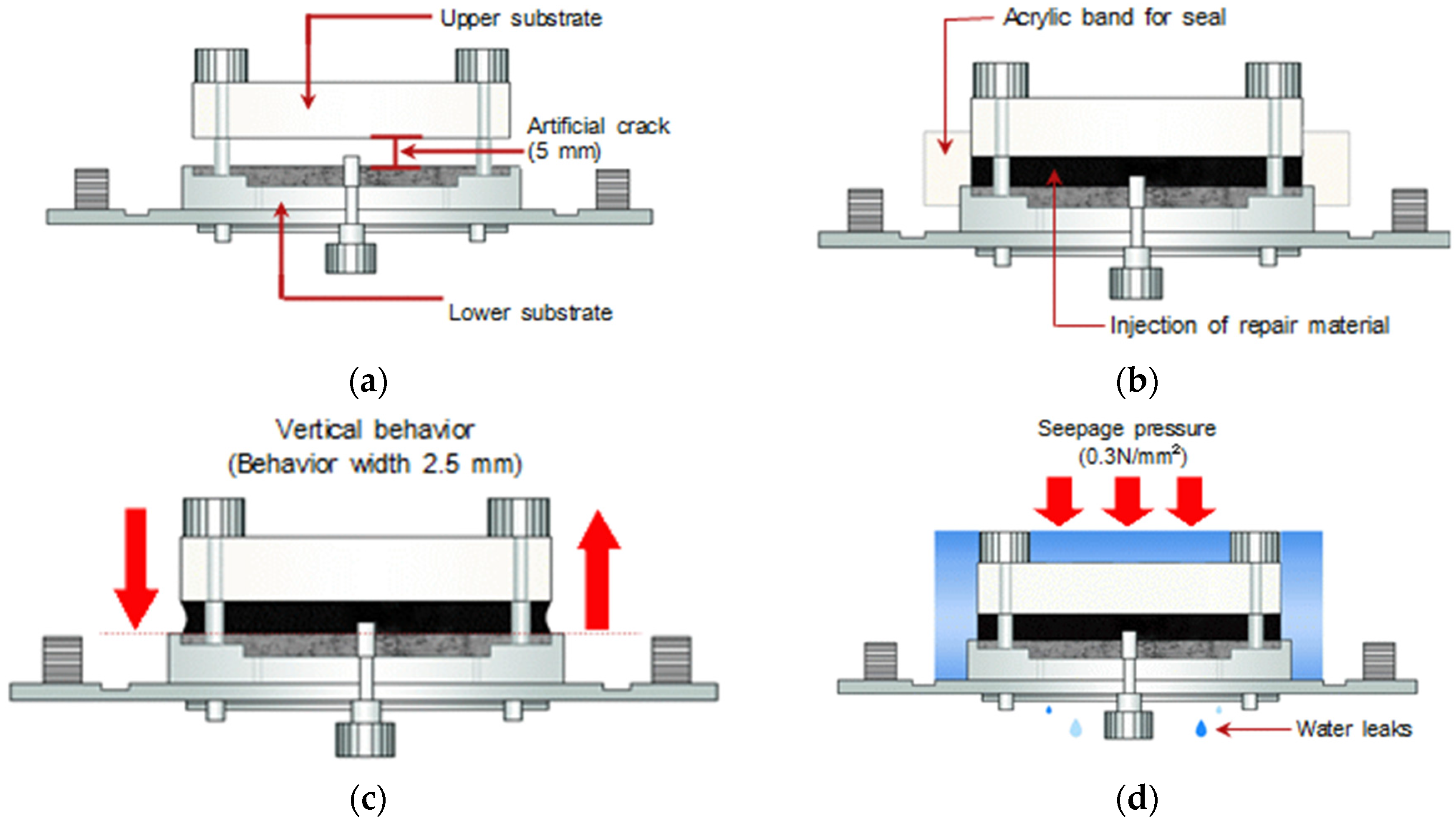
2.1. Overview

The proposed artificial-crack-behavior test method is used for the purpose of evaluating the performance of water leakage repair materials in a continuous crack behavior environment. In this test, an artificial-crack test specimen is used to apply the crack behavior environment [13] added to the cracks normally and quantitatively. An overview of the proposed artificial-crack-behavior test method is shown in Figure 1. A 5-mm-wide artificial crack (Figure 1a) is set in the gap between the upper and lower grounds, water leakage repair materials are injected into such artificial crack (Figure 1b), the status of the repair materials is identified by applying quantitative behavior (Figure 1c; i.e., fatigue load), and the existence of water leaks is determined by additionally applying constant water pressure (Figure 1d).

2.2. Artificial Cracks

As the cracks in actual concrete structures vary in form, width, and depth, it is difficult to meet the basic conditions of the test evaluation, such as application of the same standards and production of all the specimens under the same conditions. As such, artificial cracks were used in this study to ensure the reproducibility of the crack behavior conditions (cracks with the same form, type, depth, width, etc.). For the artificial cracks, a 5-mm spacer was fixed on the lower specimen, the upper specimen was placed on top of such spacer, and the gap was thus set as a 5-mm artificial crack width (Figure 1a).

2.3. Micro-Behaviors of the Artificial Cracks

The micro-behaviors of structural cracks are subjected to the various effects of the contraction and expansion of the structural members due to the temperature and humidity changes that occur, the equipment vibration, the vehicle operation, and the changes that occur in the earth and water pressure (quantity), flow rate, and differential settlement, and as such, it is very difficult to quantitatively set the amount of behaviors [14]. Thus, in this study, 100-cycle repetition up and down at a 2.5 mm behavior width for 1 min per cycle was set as the quantitative standard for the behavior by referring to the behavior fatigue resistance test conditions of building materials specified in KS (Korea Standard) F4935 [15] with respect to the micro-behavior standards of structural cracks.

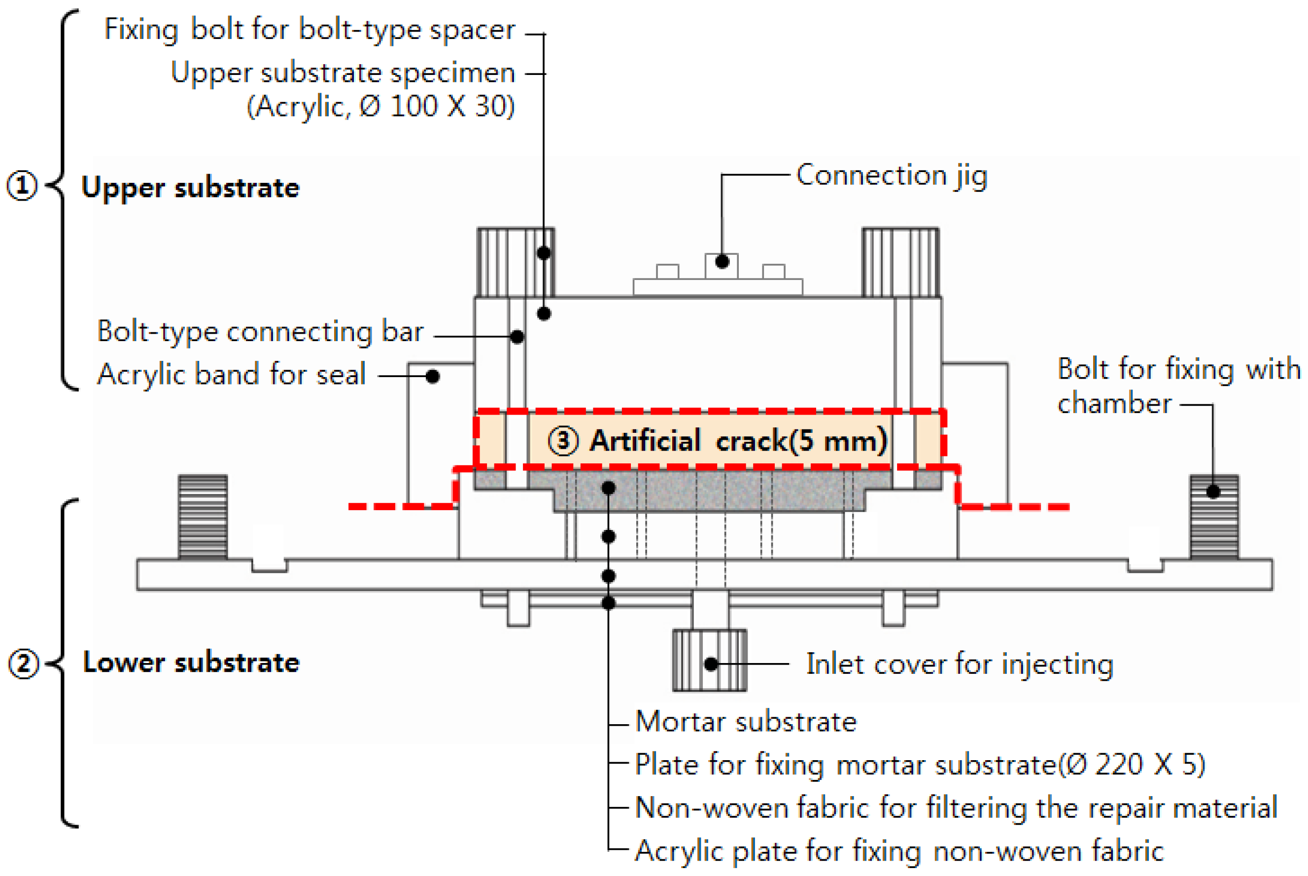
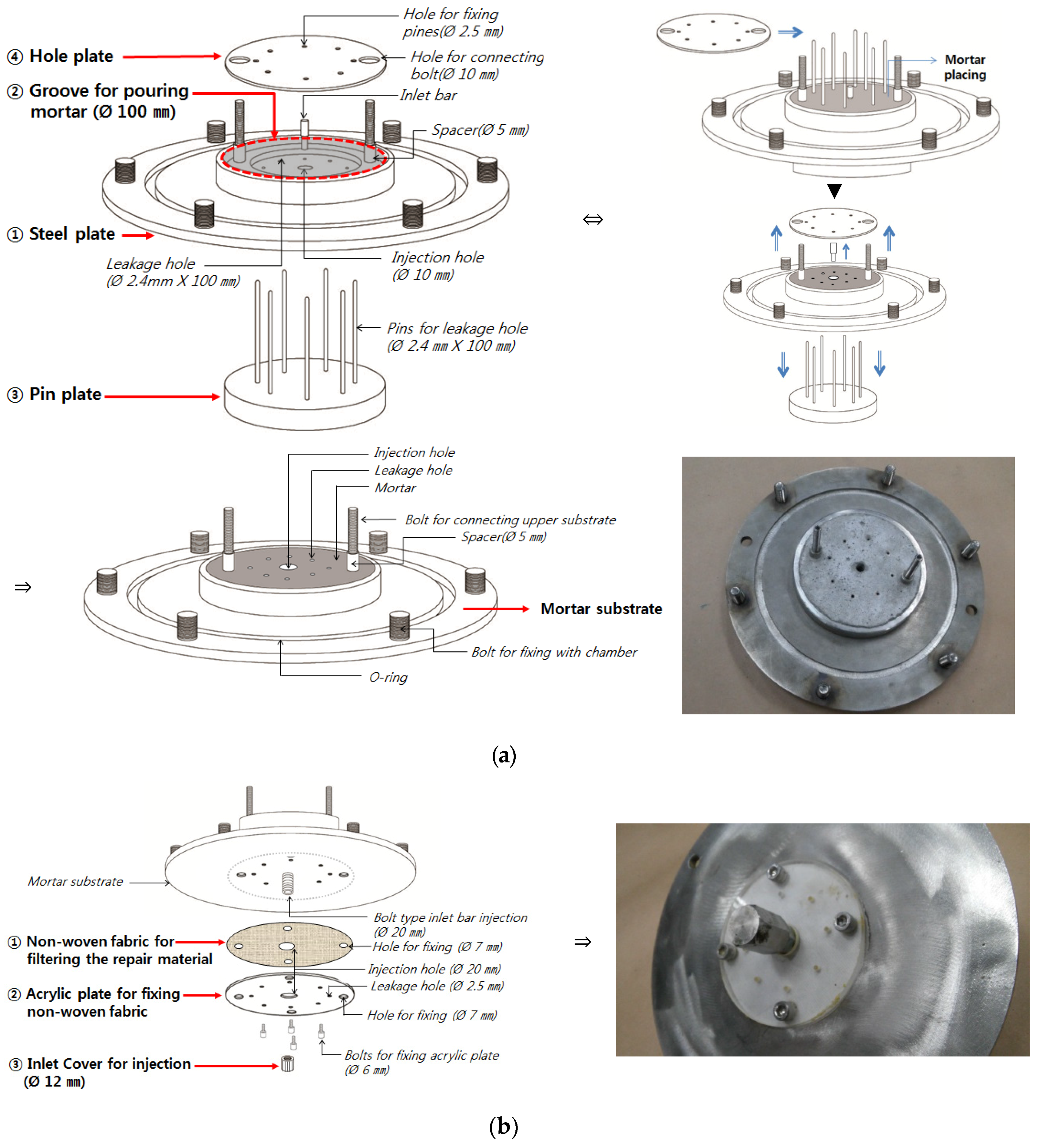
2.4. Artificial-Crack Specimens

For the artificial-crack-behavior test, artificial-crack specimens that ensure the standard specimen production and small repair material injection deviations were produced for use. As shown in Figure 2, the artificial-crack specimens were composed of an upper substrate (Figure 2-①) and a lower substrate (Figure 2-②). A spacer (Φ5 mm) was placed in the center between the upper and lower substrates, and this gap was defined as the artificial crack (Figure 2-③). In this study, the Φ5 mm size for the artificial crack was selected in accordance to the results of a prior study. In this study, crack widths of 1 mm, 3 mm, 5 mm, 7 mm and 10 mm were studied respectively, and the results showed that the crack behavior response was clearly represented. In accordance to the results, the crack width of 5 mm was selected, but in the testing methods, spacers with adjustable heights between 1 mm and 10 mm were used to control the width of the artificial crack.

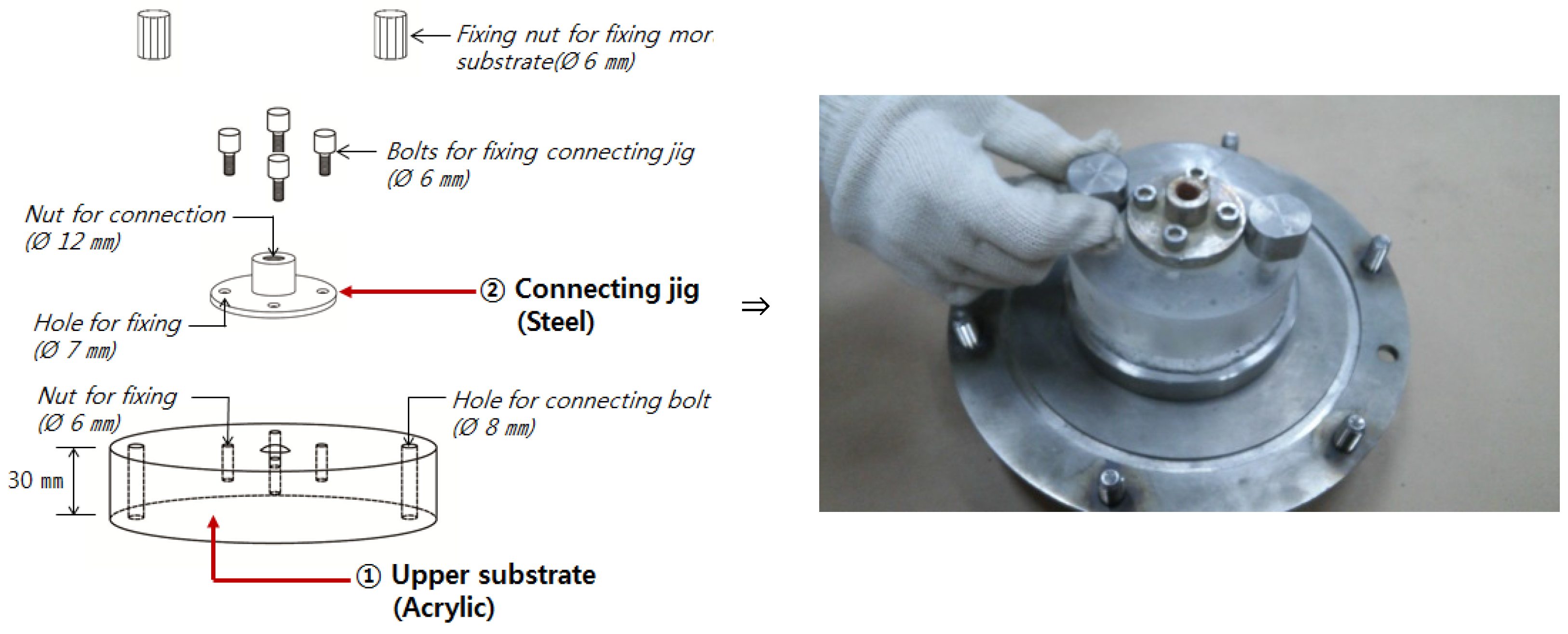
(1) Upper-Substrate Details

The details of the upper substrate are shown in Figure 3. The upper substrate (Figure 3) was made of acrylic materials and was installed parallel to a 5-mm spacing by the lower substrate and the spacer (Φ5 mm). The 5-mm spacing ensures that the cracks can be filled with water leakage repair materials, that vertical repetitive movement can be performed in the crack behavior testing process, and that the water tightness of the repair materials can be observed by applying water pressure. In addition, a fixing jig (mJig, Figure 3) made of steel was installed at the center of the upper substrate for connecting the artificial-crack specimen and the universal testing machine (UTM) (Woo-jin Inc., Soowon, Korea) for the purpose of testing the crack behavior.

(2) Lower-Substrate Details

The details of the lower substrate are shown in Figure 4. The lower substrate (Figure 4a) consisted of a steel plate, a groove for the mortar plate, a pin plate, a pinhole plate, and other accessories (Figure 4b). In the central part of the steel plate (Figure 4a-①), a groove (Figure 4a-②) for the placement of a mortar substrate with a 100-mm diameter and a 15-mm thickness was placed, where the mortar substrate represents the concrete surface. An injection hole was made in the central part of the mortar substrate for injecting the repair materials, and a number of leakage holes were made around it to serve as cracks through which the water would flow when water pressure was applied. For the production of the mortar substrate, an inlet bar and a pin plate (Figure 4a-③) were installed in the groove for the mortar located in the center of the steel plate, and the mortar was covered with a hole plate and was cured for 72 hours (3 days) after its placement. After the hardening of the mortar, the pin plate, inlet bar, and hole plate were removed, and then the mortar was allowed to stand for 168 hours. The other accessories (Figure 4b) included non-woven fabric, an acrylic plate, and an inlet cover. The non-woven fabric (Figure 4b-①) was made of polyethylene materials and served to prevent the leakage of the repair materials, which usually leak out through the leakage hole during the testing process. The acrylic plate (Figure 4b-②) served to prevent the non-woven fabric from being damaged by the pressure of the repair material injector or permeability tester, and to firmly fix it in place. The inlet cover (Figure 4b-③) served to prevent leakage when the injection of the repair materials was completed. It was removed in the crack behavior test and was installed again in the permeability test.

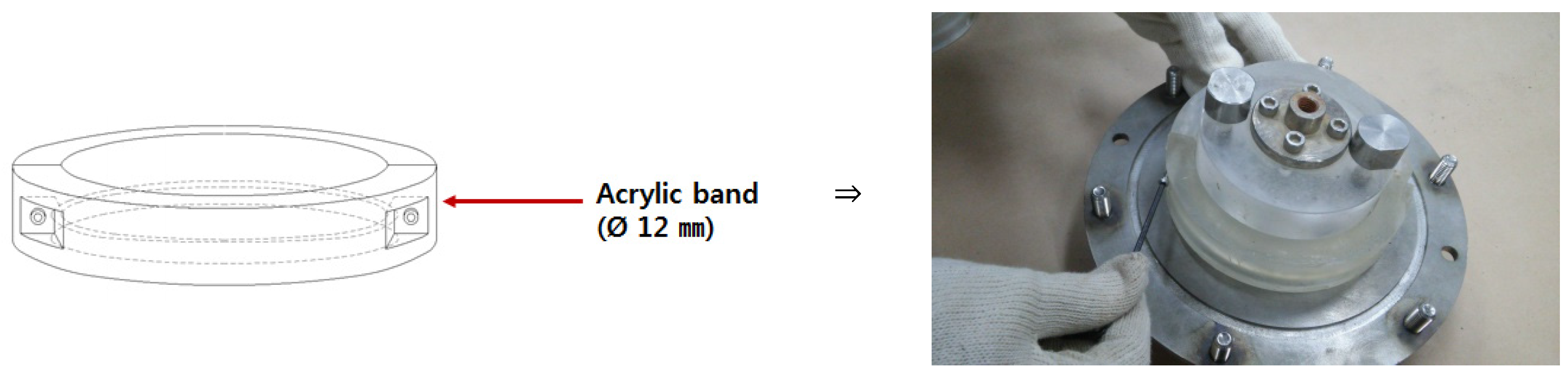
(3) Acrylic Band for Connecting the Upper and Lower Parts

After the assembly of the upper and lower substrates, an acrylic band was attached as shown in Figure 5. This device was made of transparent acrylic materials so that it could prevent the water leakage repair materials from leaking due to the pressure of the outlet when injecting the repair materials into the artificial crack, and so that it could allow the checking of the filling status. This device was installed prior to the injection of the repair materials and was removed just before the crack behavior test.

3. Repair Materials

The 15 repair materials in each of three types from the five series (synthetic rubber, cement, acryl, epoxy, and urethane) indicated in the international standard ISO TR 16475 (Guidelines for the Repair of Water Leaks and Cracks in Concrete Structures) [16]. For the classification, the materials that were used were referred to as “synthetic rubber-RG”, “cement-CG”, “acrylic-AG”, “epoxy-EG” and “urethane-UG”, and the three types of materials respectively used by each series were marked with “1”, “2” and “3” (e.g., “RG-1”, “RG-2” and “RG-3” for synthetic rubber). Below are the main components and properties of the materials that were used.
Table 1 shows the synthetic-rubber-based repair materials [17,18]. These materials have the flexibility of gel due to the combination of polymer resin such as rubber and asphalt with an inorganic component like bentonite, and exhibit uncured properties that enable their attachment to a wet surface due to their expansion when contacting water. As shown in Table 2, the cement-based repair materials are polymer-cement-slurry-based materials made by mixing ultra-fine cement (maximum diameter: less than 16 μm) with polymer dispersions and used for the repair of water leaks and cracks like micro-cracks (0.05 mm). The acrylic-based repair materials are shown in Table 3. These materials react when contacting water as acrylic acid polymer, and manifest the viscosity properties of the jelly type after the reaction. Table 4 shows the epoxy-based repair materials [19]. The main component of such materials is synthetic resin, such as amine and polyamide, and they have properties that enable curing both in a wet and a dry state. The urethane-based repair materials are shown in Table 5. These materials have as its components urethane resin and a curing agent, and exhibit properties that form an expandable closed cell or a hydrophilic gel.

4. Performance Evaluation of Water Leakage Repair Materials

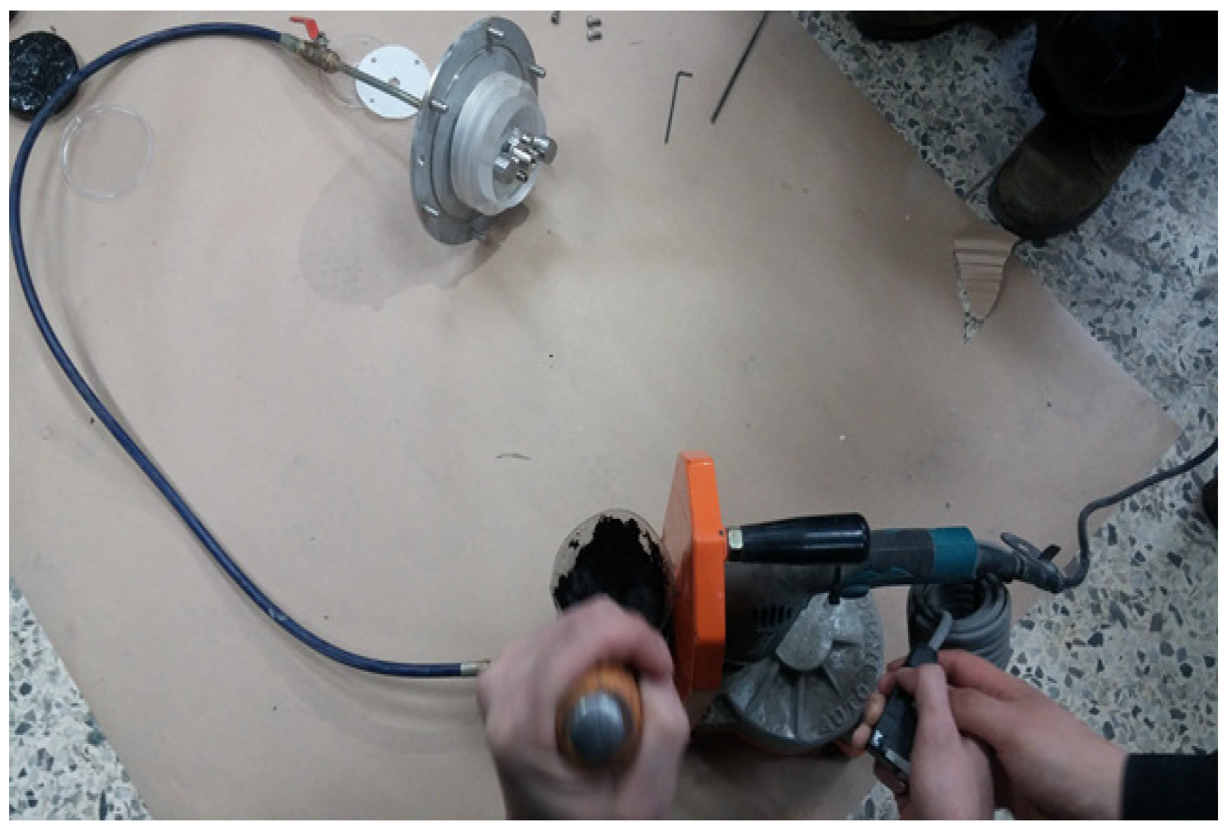
4.1. Injection of Water Leakage Repair Materials

After the completion of the assembly, 45 artificial-crack specimens were allowed to stand for one hour in water, as shown in Figure 6, and were then taken out of the water and were injected with water leakage repair materials, as shown in Figure 7. This was done to reproduce a wet environment for the artificial cracks because the underground water leakage cracks are always in a wet state. For the injection equipment, the one specified in accordance with the characteristics of each repair material and its specifications (small injector or syringe, other injection equipment available, etc.) was used. The inlet of the specimen with the injection completed was tightly covered with an inlet cover for injection (Φ12 mm), as shown in Figure 8, and the specimen was allowed to stand for 24 hours under 20 °C temperature and 65% humidity.

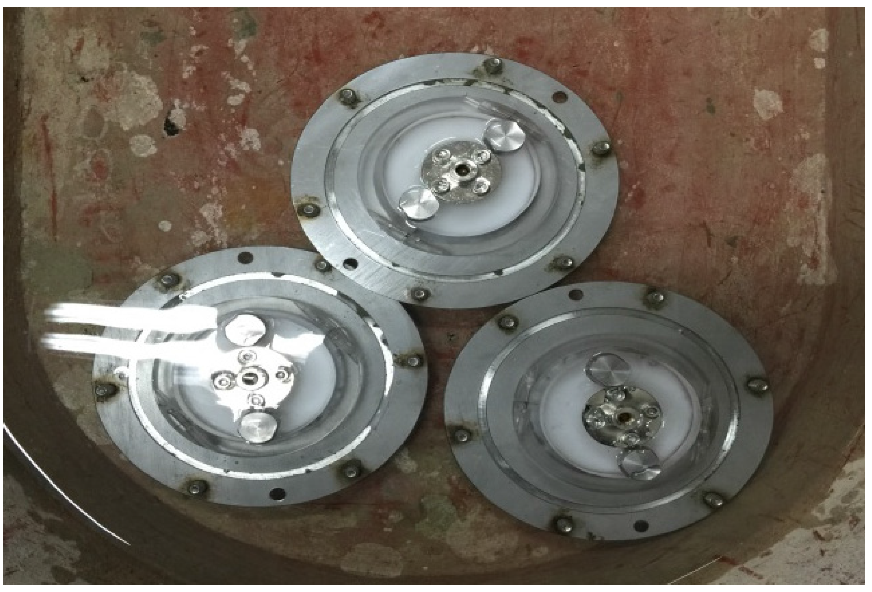
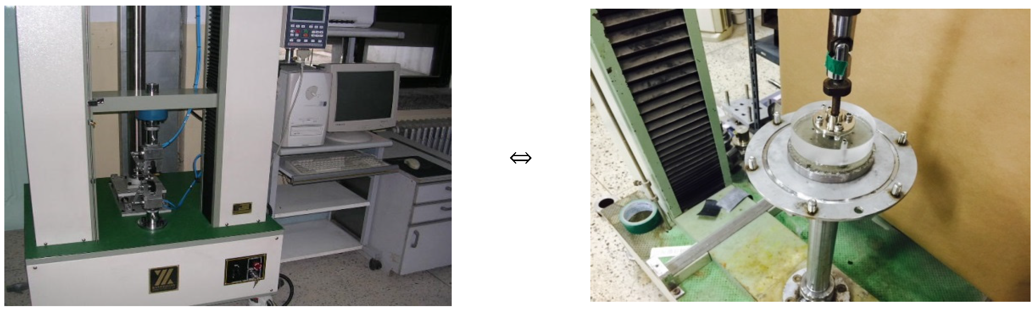
4.2. Specimen Installation for the Crack Behavior and Permeability Tests

The fixing jig installed on the surface of the upper substrate (Figure 3) mounted on the upper part, and the fixing bolt attached to the lower testing device, were connected to the UTM (Figure 9) and the OUTPUT permeability test device (Figure 10) for the imposition of mobility and water pressure.

4.3. Crack Behavior and Permeability Tests

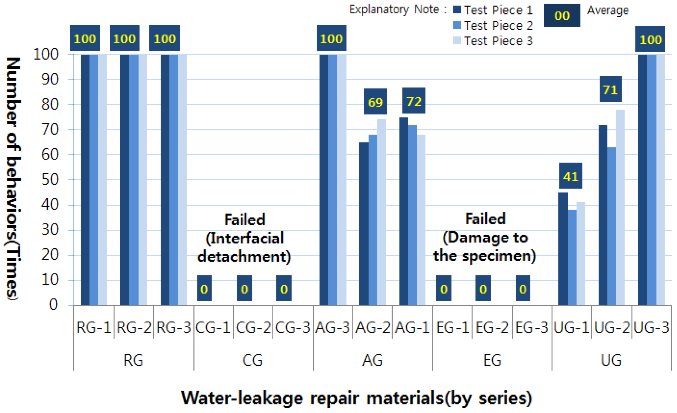
(1) Crack Behavior Test

From each of the specimens completed as discussed in Section 4.1, the acrylic band (release prevention band of the water leakage repair materials) was removed, and a UTM was installed as shown in Figure 9 so that up and down movements could be repeatedly applied in the crack behavior test. During the crack behavior test, the crack behavior width was 2.5 mm for 1 minute per cycle, totaling 100 cycles. The temperature conditions were the same as the laboratory temperature conditions cited in Section 4.1. During the crack behavior duration of 100 cycles, not only the leaks, tears, cracks, and dents of the repair materials but also the detachment of the adhesive surface with the repair materials and the artificial crack surface were checked. In particular, if the adhesive surface with the repair materials and the surface of the artificial crack were detached (eliminated) in the middle of the crack behavior load, there was no responsiveness to the crack behavior, and the performance as a repair material was lost. Therefore, this was recorded as a “failure.”

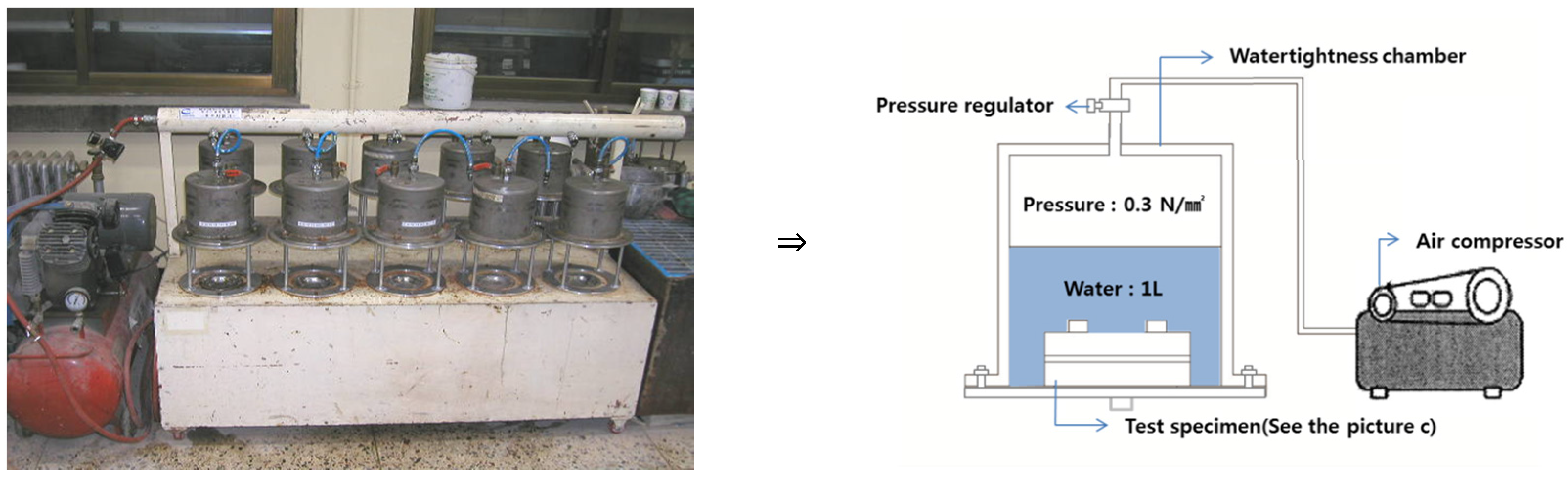
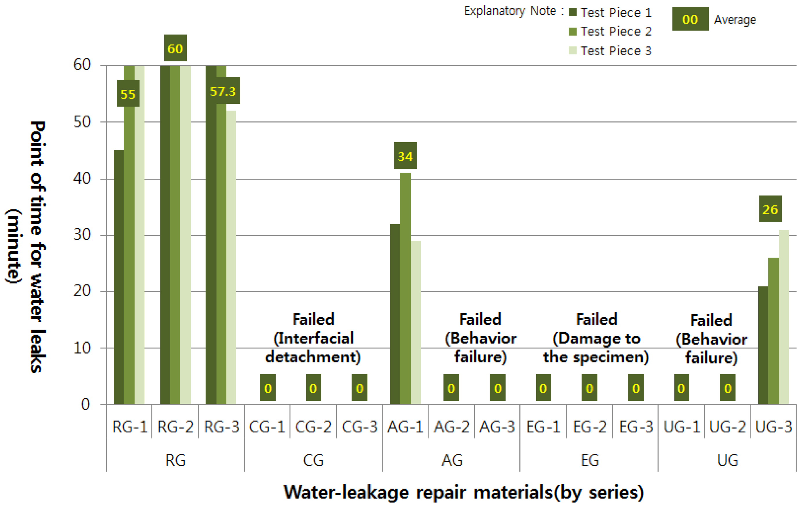
(2) Permeability Test

After the completion of the crack behavior test, a permeability test was conducted by applying the water pressure of the OUTPUT method with the specimens that showed responsiveness to the crack behavior (the specimens in which the repair materials maintained their adhesiveness on the surface of the artificial crack) as the target (not including the specimens that failed to respond to the crack behavior due to the detachment of the adhesive surface from the artificial-crack specimen). For the permeability test, the specimen was installed in the air compressor and permeability test chamber, as shown in Figure 10, and the chamber was filled with water. The chamber was connected to the air compressor, and 0.3 N/mm2 pressure (about 30-m-deep underground pressure) was applied to it, and then the point in time (minute) at which water leakage occurred was checked. If water leakage did not occur, the test results were recorded after allowing the specimen to stand for 1 hour. The temperature conditions were maintained at the laboratory temperature conditions cited in Section 4.1. In the permeability test, the main focus was on the existence of water leakage rather than on the calculation of the quantitative data on the amount of water leakage. This was because with regard to the water leaks in concrete structures, the mere existence of water leakage, regardless of the amount of water that is leaking out, is an important criterion for judgment as a defect. Accordingly, in this study, it was determined that if water leakage occurred, the water tightness performance of the repair materials was lost. Therefore, if water permeability occurred, it was recorded as “permeable,” and if it did not occur, it was recorded as “not permeable”.

4.4. Test Results

With respect to the crack behavior test results of the repair materials injected into the artificial crack, the status of the repair materials is summarized in Table 6 and Figure 11. In addition, the water tightness of the repair materials as determined through the permeability test (determination of re-leakage risk after the occurrence of the crack behavior) done after the completion of the crack behavior test is shown in Table 7 and Figure 12. The status of the repair materials for each series as shown in the crack behavior and permeability tests is shown below.

(1) Synthetic-Rubber-Based (RG) Repair Materials

The crack behavior test results showed that all the nine specimens responded to the 100-cycle crack behaviors. The observation with the unaided eye after the completion of the crack behavior test revealed that RG-1sustained leaks due to its low viscosity whereas RG-2 and RG-3showed fewer leaks than RG-1 due to their higher viscosity compared to RG-1. In the permeability test, RG-1 and RG-3 exhibited permeability in one of the three specimens, and RG-2 was shown to be impermeable in all the three specimens.

(2) Cement-Based (CG) Repair Materials

Based on the crack behavior test results, all the nine specimens of CG-1, CG-2, and CG-3 were determined to be “failures” as they showed the phenomenon of being detached from the main body immediately after the start of the crack behavior test. Therefore, the permeability test was not conducted.

(3) Acrylic-Based (AG) Repair Materials

The crack behavior test results showed that in the case of AG-1, phenomena such as leaks and detachment did not occur in the nine specimens, but the excitation phenomenon was observed on the adhesive surface of the specimens and in the materials of three specimens. They, however, were all found to have passed the 100-cycle crack behavior test. In the case of AG-2 and AG-3, as the phenomenon of being detached from the surface of the specimen and the materials occurred at an average of 69 cycles in AG-2 and at an average of 69 cycles in AG-3, they were determined to be “failures.” According to the permeability test results, even AG-1, which passed some of the crack behavior tests, was not able to withstand the water pressure and lost most of the materials, and the permeability test was not conducted for AG-2 and AG-3, which did not pass the crack behavior test.

(4) Epoxy-Based (EG) Repair Materials

According to the crack behavior test results, the phenomenon of being damaged occurred in all the specimens of EG-1, EG-2, and EG-3, which were determined to be “failures.” As such, the permeability test was not conducted.

(5) Urethane-Based (UG) Repair Materials

According to the crack behavior test results, the excitation between the main body and the material occurred in three specimens of UG-3, but they passed the 100-cyclecrack behavior test. In the six specimens of UG-1 and UG-2, as the detachment of the material from the main body occurred at an average of 41 cycles in UG-1 and at an average of 71 cycles in UG-2, as shown in Figure 10, they were determined to be “failures.” The permeability test results showed that even the three specimens of UG-3 that passed the crack behavior test exhibited permeability, and the permeability test was not performed for UG-1 and UG2 due to their failure in the crack behavior test.

4.5. Discussion

Cyclic behavior and pressure were applied with respect to the artificial cracks into which the repair materials were injected, and Table 8 shows a summary of the responsiveness and water tightness performance of the water leakage repair materials.
(1) In the case of the synthetic-rubber-based (RG) materials, the slip-down phenomenon occurred in the crack behavior test, but all the nine specimens showed responsiveness to the crack behavior. This suggests that such materials respond flexibly to the behavior of the cracks that occur in concrete structures due to the elastic properties of non-curable polymer resin using asphalt with a rubber component and a viscous nature. With respect to the permeability resistance after the completion of the crack behavior test, seven synthetic-rubber-based (RC) specimens did not exhibit permeability while the other two specimens did, as shown in Table 8. Therefore, the existence of water leakage was determined according to the differences in rubber viscosity of the materials in the case of the synthetic-rubber-based (RG) repair materials.
(2) In the cement-based (CG) and epoxy-based (EG) repair materials, all the 18 specimens did not show responsiveness to the crack behavior. In the case of the cement-based (CG) material, the rigid material properties with little flexibility made it impossible to proceed with the test due to the adhesive surface’s detachment from the main body, which was caused by even a microscopic crack behavior. As for the epoxy-based (EG) material, the main body of the specimen (attached equipment) was damaged due to the solid properties after the curing, and as such, the test could not be conducted. In particular, although the epoxy-based (EG) repair material has very strong material strength, it does not have sufficient responsiveness to the crack behavior after the repair, and the repaired area can be damaged under the continuous crack behavior effects, posing the risk of re-leakage. In this regard, the crack behavior responsiveness should be reviewed when the cement-based (CG) and epoxy-based (EG) water leakage repair materials are applied to the water leakage or crack areas in concrete structures.
(3) As for the acrylic-based (AG) and urethane-based (UG) repair materials, all the 12 AG-2, AG-3, UG-1, and UG-2 specimens did not pass the 100-cyclecrack behavior test, and only six AG-1 and UG-3 specimens were found to have crack behavior responsiveness. The observation results revealed, however, that the excitation phenomenon occurred at certain places. This excitation resulted in the loss of the repair materials in the permeability test, and as such, permeability was shown by all the specimens. This shows that as the soft-body acrylic-based material of the jelly type and the urethane-based (RG) material that takes the form of silicon are harder than the synthetic-rubber-based (RG) materials and are softer than the cement-based (CG) or epoxy-based (EC) materials, they have a large material deviation in crack behavior responsiveness and permeability resistance.
(4) The summary of the artificial-crack-behavior test results shows that of the 45 types of repair materials, 24.4% were found to have crack behavior responsiveness, and about 75.6%were lacking in responsiveness. In addition, the permeability test confirmed that about 15.6% did not show water leakage whereas about 84.4% did.
(5) With regard to the crack behavior responsiveness performance deviation, shows that the material deviation of the synthetic polymer (RG) was 0% as its average crack behavior was 100 times; that of acryl (AG)was 31%, with 80.3 times average crack behavior; and that of urethane (UG)was 59%, with 70.7 times average crack behavior. These indicate that in the crack behavior responsiveness performance, the greater the deviation is, the lower the material performance, and the smaller the deviation is, the higher the material performance. As the cement-based (CG) and epoxy-based (EG) materials were not the test subjects in this study, their crack behavior responsiveness performance deviations were not recorded.
(6) The water tightness performance deviation was calculated after the completion of the crack behavior test, and as such, it was difficult to estimate the quantitative deviations depending on the status of each series. As shown in, however, it was confirmed that based on the permeability test time (60 min), the average water tightness performance of synthetic rubber (RG) was 57.4 min (95.6%), that of acryl (AG) was 11.3 min (18.8%), and that of urethane (UG) was about 8.7 min (14.5%). As the cement-based (CG) and epoxy-based (EG) materials were not the test subjects in this study, their water tightness performance deviations were not recorded.

5. Conclusions

This study proposed an artificial-crack-behavior test method as a quality control method for the materials used in the water leakage or crack repairs of concrete structures. The method’s performance was evaluated by applying it with the 15 kinds of repair materials (total of 45 specimens) of the five series as the targets, and the results showed that only 15.6% of the specimens exhibited crack behavior responsiveness and water tightness, and 84.4% of the specimens did not respond appropriately to the crack behaviors and exhibited an inability to resist moisture when water pressure was applied. Among them, the synthetic-rubber-based (RG) material was found to exhibit crack behavior responsiveness and permeability resistance. The validity of this method as a standard performance verification method for the materials used for water leakage or crack repairs was thus confirmed.
The results of this study show that there is a need to come up with a performance verification method and with performance verification standards for the water leakage repair materials for the safe maintenance of the current concrete structures, and that the proposed test method can be used as a standard test method for the performance evaluation of the water leakage repair materials.
For future research work, a study not only on the artificial-crack-behavior test method proposed in the present study but also on the quality control method for responding to the other environmental conditions under which water leakage or cracks occur in concrete, and its standards, will be conducted.

Acknowledgement

This research was supported by a grant (16RERP-B082204-03) from Residential Environment Research Program funded by the Ministry of Land, Infrastructure, and Transport of the South Korean government.

Author Contributions

Soo-Yeon Kim and Sang-Keun Oh conceived and designed the experiments; Soo-Yeon Kim performed the experiments; Soo-Yeon Kim, Byoungil Kim and Sang-Keun Oh analyzed the data; Soo-Yeon Kim, Byoungil Kim and Sang-Keun Oh wrote the paper.

Conflicts of Interest

The authors declare no conflict of interest.

Abbreviations

The following abbreviations are used in this manuscript:
KSKorean industrial Standards
ISOInternational Organization for Standardization
TRTechnical Report
RGSynthetic-rubber-based repair materials Grouting
CGCement-based repair materials Grouting
AGAcrylic-based repair materials Grouting
EGEpoxy-based repair materials Grouting
UGUrethane-based repair materials Grouting
UTMUniversal Testing Machine

References

  1. Jung, W.-S.; Ali Khan, M.; Jeon, Y.H. A study on the geochemical behaviors of FE (ll) and As (V) in underground environment. Korean Soc. Eng. Geol. 2010, 2010, 337–340. [Google Scholar]
  2. Lee, K.-W.; Heo, T.-S.; Yang, S.-B. Review on the Proper Waterproofing Methods and Waterproof Agents for Underground Structures under Chloride Attack Environment in Incheon International Airport; Yooshin Engineering Corporation: Seoul, Korea, 2004; pp. 181–206. [Google Scholar]
  3. Chang, S.-M.; Choi, S.M.; Oh, S.-K. Analysis of the temperature-humidity changing characteristics by the applying type of the waterproofing methods in the basement parking lot in the winter. J. Regional Assoc. Architect. Inst. Korea 2014, 16, 217–223. [Google Scholar]
  4. CHUNGWOO MEDIA. Guide to Design and Construction for Architectural Water Proofing System; CHUNGWOO MEDIA Co., Ltd.: Seoul, Korea, 1992; pp. 33–44. [Google Scholar]
  5. Park, K.-P.; Kim, S.-S.; Lee, J.-B.; Cho, N.-Y.; Jeong, H.-S. Deterioration property of tunnel concrete according to environments. J. Korea Inst. Struct. Maint. Insp. 2009, 2009, 286–287. [Google Scholar]
  6. The Applied Technology Council. Repair of Earthquake Damaged Concrete and Masonry Wall buildings; The Applied Technology Council: Redwood City, CA, USA, 1998. [Google Scholar]
  7. National Groundwater Information Center. Groundwater Observation Statistics; National Groundwater Information Center: Seoul, Korea, 2016. [Google Scholar]
  8. Lee, J.-Ye.; Hong, K.-C.; Whang, S.-J. Drainage System; Institute of Technology of C.G Engineering & Consulting Co., Ltd.: Seoul, Korea, 2009; pp. 7–27. [Google Scholar]
  9. Protecto Wrap Company. Concrete Repair Manual Concrete Sumps and Surfaces (Solutions for Repair and Coating); Protecto Wrap Company: South Cherokee Street Denver, CO, USA, 2009; pp. 8–11. [Google Scholar]
  10. Jeong, J.-S.; Lee, S.-G.; Lee, K.-Y.; Jeong, H.-O.; Kim, H.-H. A case study on the effects on underground structure due to changes in the ground water level and ground stress. Korean Geo-Environ. Soc. 2015, 16, 13–21. [Google Scholar]
  11. Oh, S.K. A new approach on waterproofing and water-leakage repair technology of concrete structure. Korea Concr. Inst. 2002, 2002, 101–118. [Google Scholar]
  12. Song, B.-C. Leakage of water on concrete structures and recently repair methods. Korea Concr. Inst. 2012, 24, 29–33. [Google Scholar]
  13. Park, S.-Y.; Park, I.-J.; Lee, J.-J.; Choi, S.-H.; Kim, S.-I. Analysis of dynamic behavior for underground structures under earthquake loading. Tunnelling Technol. 2007, 9, 205–217. [Google Scholar]
  14. American Concrete Pavement Association. Concrete Crack and Partial-Depth Spall Repair Manual (Unified Facilities Criteria); American Concrete Pavement Association: Rosemont, IL, USA, 2004. [Google Scholar]
  15. Korean Agency for Technology and Standards. Sealer of Injection Type for Water Leakage Maintenance of Adhesive Flexible Rubber Asphalt Series (KSF 4935); Korean Agency for Technology and Standards: Seoul, Korea, 2008. [Google Scholar]
  16. International Organization for Standardization. ISO/TR 16475, Guidelines for the Repair of Water Leakage Cracks in Concrete Structures ISO/TC 71; International Organization for Standardization: Geneva, Switzerland, 2011. [Google Scholar]
  17. Kwon, S.-W.; Oh, M.-H.; Kwat, K.-S.; Oh, S.-K. Sealer of injection type for water leakage maintenance of adhesive flexible rubber asphalt series. J. Korea Ins. Build. Constr. 2006, 6, 87–91. [Google Scholar] [CrossRef]
  18. Oh, S.-G.; Lee, J.-Y.; Park, K.-B.; Oh, J.-S. Water-Leakage Maintenance Technology and Case of Architecture as Structure; Korea Infrastructure Safety Corporation: Seoul, Korea, 2012. [Google Scholar]
  19. ACI Committee E706. Field Guide to Concrete Repair Application Procedures, Structural Crack Repair by Epoxy Injection; American Concrete Institute: Farmington Hills, MI, USA, 2010. [Google Scholar]
Figure 1. Overview of the artificial-crack-behavior test. (a) 5-mm-artificial-crack test specimens; (b) Injection of repair material; (c) Vertical crack behavior (100 cycles); (d) Water pressure (60 mins).
Applsci 06 00253 g001
Figure 2. Artificial crack specimen structure concept.
Applsci 06 00253 g002
Figure 3. Detailed process for the upper substrate.
Applsci 06 00253 g003
Figure 4. Detailed process for the lower substrate. (a) Detailed process for the mortar substrate; (b) Detailed installation process of the other test equipment.
Applsci 06 00253 g004
Figure 5. Detailed process for the acrylic band.
Applsci 06 00253 g005
Figure 6. Rest in underwater condition for 1 hour.
Applsci 06 00253 g006
Figure 7. Repair material injection.
Applsci 06 00253 g007
Figure 8. Inlet bar for injection Installation.
Applsci 06 00253 g008
Figure 9. Universal testing machine (UTM).
Applsci 06 00253 g009
Figure 10. Permeability test chamber (output).
Applsci 06 00253 g010
Figure 11. Leakage repair material (by series) behavior response cycle.
Applsci 06 00253 g011
Figure 12. Leakage repair material (by series) water leakage response time.
Applsci 06 00253 g012
Table 1. Synthetic rubberized gel grout.
TypesComponentsProperties
RG-1Acrylamide, persulfate (mixed with one or two kinds of sodium, ammonium, and potassium), asphalt, and other additives(1) Solids: 85%–90%
(2) High-viscosity + low-viscosity non-curable composite liquid gel
(3) Diaphragm structure with a sawtooth structure (diaphragm support structure)
(4) Volume expansion due to the contact with water
RG-2Asphalt, inorganic filler for viscosity adjustment, processor oil, asphalt modifier, strength reinforcement agent, heat resistance reinforcement agent, adhesion reinforcement agent, anti-flow additives, used tires, aqueous modifier, etc.(1) Solids: 95%–99%
(2) High-viscosity non-curable mastic asphalt
(3) Polar covalent bond structure of hydrophilic and lipophilic groups
RG-3Asphalt, bentonite, oil, rubber, water-soluble polymer resin, etc.(1) Solids: 90%–95%
(2) Highly adhesive non-curable bentonite rubberized asphalt
Table 2. Cement-based repair materials.
TypesComponentsProperties
CG-1Cement, accelerator, fluidizing agent, water, other additives, etc.(1) Solids: 97%–100%
(2) Specific gravity: 1.9–2.0
(3) Non-shrink grout non-base material
CG-2Cement, sand, fluidizing agent, expansion agent, mixing water, etc.(1) Solids: 95%–100%
(2) Specific gravity: 1.57
(3) Fluidizing agent expansion material
CG-3Cement, fluidizing agent, curing regulator, water, other additives, etc.(1) Solids: 97%–100%
(2) Specific gravity: 1.32
(3) Ultra-rapid water-stop materials
Table 3. Acrylic-based repair materials.
TypesComponentsProperties
AG-1Acrylate (metal hydroxide aqueous solution + acrylic acid + methacrylic acid), persulfate, amine (redox polymerization catalyst, acrylic acid meal salts, cross-linking agent, etc.(1) Mixed viscosity: Less than 5 cps
(2) Acrylate-based water-stop agent
(3) Volume expansion: 400%
(4) Curing time: 120 seconds
AG-2Acrylic acid metal salt, acrylamide, triethanolamine, glycerin, potassium femicyanide, sodium persulfate, etc.(1) Mixed viscosity: Less than 3 cps
(2) Acrylate-based water-stop agent
(3) Volume swelling: 200%
(4) Elongation: 70% after condensation
AG-3Main (sodium polyacrylate, acrylamide- sodium acrylate, water), hardener (sulfate compounds, water), accelerant (triethanolamine, water)(1) Mixed viscosity: less than 20 cps
(2) Acrylic seal grouting agent
(3) Solubility: Soluble in water
(4) Boiling point/melting point: 100 °C /−10 °C
Table 4. Epoxy-based repair materials.
TypesComponentsProperties
EG-1Epoxy resin + amine (dry type) Main: Hardener = 2:1(1) Two-component low-viscosity epoxy non-shrink grout
(2) Pot life: About 90min (20 °C)
(3) Finger touch cure time: 50 min(20 °C)
(4) Complete cure time: About 8 hr (35 °C)
(5) Exterior color: Yellowish brown (main)
EG-2Epoxy resin + polyamidamine (wet type) Main: Hardener = 2:1(1) Two-component low-viscosity wet-type grout
(2) Pot life: About 60min (25 °C)
(3) Finger touch cure time: 18 hr (25 °C)
(4) Complete cure time: 24–36 hr (25 °C)
(5) Exterior color: Yellowish brown (main)
EG-3Elastic epoxy sealant Main: Hardener = 1:1(1) Two-component epoxy elastic sealing grout
(2) Pot life: About 60min (23 °C)
(3) Finger touch cure time: 14hr (23 °C)
(4) Complete cure time: 24–36 hr (23 °C)
(5) Exterior color: White paste (main)
Table 5. Urethane-based repair materials.
TypesComponentsProperties
UG-1Filled reactive polyurethane polymers Xylene: 4%(1) One-component rapid-hardening elastic polyurethane
(2) Solubility: Insoluble (reacts with water)
(3) Specific gravity (20 °C): 1.26
(4) Flashpoint: 65 °C
UG-2Hydrophobic rigid non-shrink urethane(1) 2-component non-shrink high-strength polyurethane
(2) Viscosity : 532(resin) cps/23.1 °C
(3) Initial/full cure pot life: 60 minutes at room temperature/24 hours at room temperature
UG-3Polyurethane resin
Acetone (CH3CoCH3)
Other additives
(1) One-component flexible urethane foam
(2) Solubility: 1.3 g/100 ml
(3) Specific gravity (20 °C): 1.37
(4) Viscosity: 200–500 cps/25 °C
(5) Flashpoint: 0 °C
Table 6. Status of the specimens after the crack behavior test.
DivisionNaked-Eye ObservationComprehensive Judgment
RG Applsci 06 00253 i001 Applsci 06 00253 i002 Applsci 06 00253 i003RG-1: Passed (leaks occurred)
RG-2: Passed (fewer leaks occurred compared to RG-1)
RG-3: Passed (fewer leaks occurred compared to RG-1)
RG-1RG-2RG-3
CG Applsci 06 00253 i004 Applsci 06 00253 i005 Applsci 06 00253 i006CG-1, 2, 3: Failed (interfacial detachment occurred immediately after the test)
CG-1CG-2CG-3
AG Applsci 06 00253 i007 Applsci 06 00253 i008 Applsci 06 00253 i009AG-1: Passed (excitation occurred)
AG-2: Failed (interfacial detachment occurred at an average of 69 cycles)
AG-3: Failed (interfacial detachment occurred at an average of 72 cycles)
AG-1AG-2AG-3
EG Applsci 06 00253 i010 Applsci 06 00253 i011 Applsci 06 00253 i012EG-1, 2, 3: Failed (specimen damage occurred)
EG-1EG-2EG-3
UG Applsci 06 00253 i013 Applsci 06 00253 i014 Applsci 06 00253 i015UG-1: Failed(interfacial detachment occurred at an average of 41 cycles)
UG-2: Failed(interfacial detachment occurred at an average of 71 cycles)
UG-3: Passed (excitation occurred)
UG-1UG-2UG-3
Table 7. Status of the specimens after the permeability test.
DivisionPresence and absence of water leakageComprehensive judgment
RG Applsci 06 00253 i016 Applsci 06 00253 i017 Applsci 06 00253 i018RG-1: Permeable (1), not permeable (2)
RG-2: Permeable (3)
RG-3: Permeable (1), not permeable (2)
RG-1-①RG-2RG-3-③
CGFailed
(failure in crack behavior responsiveness)
CG-1, 2, 3: Failed (failure in crack behavior responsiveness occurred)
CG-1CG-2CG-3
AG Applsci 06 00253 i019Failed
(failure in crack behavior responsiveness)
AG-1: Failed (permeable for 34 min on average)
AG-2, 3: Failed (failure in crack behavior responsiveness occurred)
AG-1AG-2AG-3
EGFailed
(failure in crack behavior responsiveness)
EG-1, 2, 3: Failure (failure in crack behavior responsiveness occurred)
EG-1EG-2EG-3
UGFailed
(failure in crack behavior responsiveness)
Applsci 06 00253 i020UG-1, 2: Failed (failure in crack behavior responsiveness occurred)
UG-3: Failed (permeable for 26 min on average)
UG-1UG-2UG-3
Table 8. Comprehensive results of the artificial-crack-behavior test.
DivisionCrack Behavior Responsiveness PerformanceWater Tightness PerformanceComprehensive Results
S1S2S3S1S2S3
RGRG-1×Behavior test
Responsive: 11EA (24.4%)
Non-responsive: 34EA (75.6%)
RGRG-2Non-responsive: 34EA (75.6%)
RGRG-3×Behavior test
Responsive: 11EA (24.4%)
Non-responsive: 34EA (75.6%)
CGCG-1××××××Behavior test
Responsive: 11EA (24.4%)
Non-responsive: 34EA (75.6%)
CGCG-2××××××Behavior test
Responsive: 11EA (24.4%)
Non-responsive: 34EA (75.6%)
CGCG-3××××××Behavior test
Responsive: 11EA (24.4%)
Non-responsive: 34EA (75.6%)
AGAG-1×××××Behavior test
Responsive: 11EA (24.4%)
Non-responsive: 34EA (75.6%)
AGAG-2××××××Permeability test
Non-permeable: 7EA (15.6%)
No test/permeable, separate body: 38EA (84.4%)
AGAG-3××××××Permeability test
Non-permeable: 7EA (15.6%)
No test/permeable, separate body: 38EA (84.4%)
EGEG-1××××××Permeability test
Non-permeable: 7EA (15.6%)
No test/permeable, separate body: 38EA (84.4%)
EGEG-2××××××Permeability test
Non-permeable: 7EA (15.6%)
No test/permeable, separate body: 38EA (84.4%)
EGEG-3××××××Permeability test
Non-permeable: 7EA (15.6%)
No test/permeable, separate body: 38EA (84.4%)
UGUG-1××××××Permeability test
Non-permeable: 7EA (15.6%)
No test/permeable, separate body: 38EA (84.4%)
UGUG-2××××××Permeability test
Non-permeable: 7EA (15.6%)
No test/permeable, separate body: 38EA (84.4%)
UGUG-3×××××Permeability test
Non-permeable: 7EA (15.6%)
No test/permeable, separate body: 38EA (84.4%)
Note: Responsive/non-permeable: ●; Non-responsive/no test/permeable, separate body: ×.

