Article

Study of the Tool Geometry Influence in Indentation for the Analysis and Validation of the New Modular Upper Bound Technique

by
Carolina Bermudo
*,
Lorenzo Sevilla
,
Francisco Martín
and
Francisco J. Trujillo
Civil, Material and Manufacturing Engineering Department, University of Malaga, Malaga 29071, Spain
*
Author to whom correspondence should be addressed.
Appl. Sci. 2016, 6(7), 203; https://doi.org/10.3390/app6070203
Submission received: 23 May 2016 / Revised: 9 June 2016 / Accepted: 24 June 2016 / Published: 12 July 2016

Abstract

:
Focusing on incremental bulk metal forming processes, the indentation process is gaining interest as a fundamental part of these kinds of processes. This paper presents the analysis of the pressure obtained in indentation under the influence of different punch geometries. To this end, an innovative Upper Bound Theorem (UBT) based solution is introduced. This new solution can be easily applied to estimate the necessary force that guarantees plastic deformation by an indentation process. In this work, we propose an accurate analytical approach to analyse indentation under different punches. The new Modular Upper Bound (MUB) method presents a simpler and faster application. Additionally, its complexity is not considerably increased by the addition of more Triangular Rigid Zones. In addition, a two-dimensional indentation model is designed and implemented using the Finite Element Method (FEM). The comparison of the two methods applied to the indentation process analysed—the new Modular Upper Bound technique and the Finite Element Method—reveal close similarities, the new Modular Upper Bound being more computationally efficient.

Graphical Abstract

1. Introduction

The application of incremental bulk metal forming processes is gaining growing interest in the current industry. These processes are being investigated due to their advantages, widely discussed in literature by different authors [1,2,3,4,5,6]. The incremental method is frequently used since it offers load reductions and workability increments in comparison with other processes. It also allows forging materials that present high resistance to deformation, obtaining large final shapes. Another important issue is the tools simplicity—normally a simple punch—and their exchangeable capability. This gives flexibility to the production, a very important feature nowadays. Finally, the high smoothness of the final workpiece deformed by these processes, the material economy and the aptitude for a complete management with Computer Numerical Control (CNC) machines can also be noted. To this end, having these processes implemented in the current industry plays an important role in achieving a competitive production.
Consequently, the indentation case study as a fundamental part of these incremental bulk metal forming processes, is considered as a necessary step in the metalworking industries. Applying indentation to a workpiece, the final shape is progressively obtained by repetitive compressions. Thus, the indentation process is no longer considered as a secondary manufacturing process. On the contrary, it is presented as an alternative to traditional plastic deformation processes. It is not difficult to find works that extensively explore possible applications related with indentation processes, like the Single Point Incremental Forming (SPIF) or the localized-incremental forging processes. These processes achieve the final shape as a result of discrete indentations throughout the whole workpiece [7,8]. Another example can be found with the Multiple Indentation processes, when a concatenation of elementary indentations is applied [9]. These new indentation based processes allow big deformation with less compression forces. Thus, the singular case study in this paper enables achieving an approximation to these new incremental processes referenced.
Several studies show that the final workpiece shape depends on the geometry of the punch employed. In addition, other process parameters can have an effect, like the step over, feed rate or penetration [10,11,12]. The purpose of this paper is twofold: first, it aims to characterize the workpiece behaviour under different punch geometries. Second, it proposes an analytical solution that can be easily applied to estimate the necessary force needed to generate plastic deformation by indentation. Thus, different punch shapes are examined under the Finite Element Method (FEM) and the Upper Bound Theorem (UBT), in order to determine the force pick value for each of the geometries considered and compare the versatility of the methods applied. We propose a general UBT application that seeks a simplification of the analysis approached. Due to its efficiency, it is presented as an alternative to other current methods.
The Upper Bound Theorem is considered one of the main analytical solutions for the metal forming process modelling. It is usually found applied in investigations of deformation processes like incremental forging, extrusion, Equal Channel Angular Extrusion/Pressing (ECAE/ECAP), orbital forming and others [13,14,15,16]. On general terms and under a plain strain hypothesis, the UBT can be expressed as << … The work realized by the superficial strengths of real traction (or compression) on a rigid-perfect plastic body is lower or the same as that realized by the superficial strengths of traction (or compression) corresponding to any other field of admissible kinematic velocities … >> [17]. Hence, the UBT can be expressed as follows:
S V T i   ×   v i   ×   d S v S D k   ×   v * d S D * + S F T i v i * d S F
where:
  • Ti: Workpiece external strengths;
  • vi: Real velocities field;
  • Sv: Surface where external load are applied;
  • k: Shear yield stress;
  • SD*: Discontinuity surface;
  • vi*: Kinematically Admissible Velocity Field (KAVF);
and SF: External surface exposed to virtual velocity field.
Additionally, under plane strain hypothesis, the material deformed offers its maximum resistance when τ = k, where τ represents the shear stress. Thus, the dissipative power value due to the internal energy will not exceed the outcome value of k × s × v*, with s being the length of the tangential velocity discontinuity line.
Working with UBT, the Triangular Rigid Zone (TRZ) alternative is the kinematic–geometrical option that allows a more accurate solution with high capacity of analysis [18]. The study of the material flow field is possible applying the TRZ choice. Each TRZ slides one over the other along the discontinuity lines of the KAVF represented by the corresponding hodograph (Figure 1). Having the KAVF defined, it is possible to calculate the forming forces and represent the velocities, strain rates and strains of the process considered. Figure 1 shows a quarter of an indentation, where the TRZ division identifies each triangle with a number, being V the velocity of the punch over the workpiece. This velocity causes a reaction over the whole part, being the blue arrow the movement of the part. The hodograpgh (Figure 1B) is built with the absolute (Vi) and relative (Vij) velocity of each TRZ.
In previous published works, we present and validate the study on indentation process by means of the new Modular Upper Bound technique (MUB) [19,20]. MUB was developed for its implementation with a flat and inclined punch (Figure 2). Particularly in this paper, the study of the punch geometry is extended to another four geometries—combinations of the flat and inclined punch—including a curve punch, which gives rise to future research where more complex shapes can be treated. Thereby, the purpose of this research is to validate MUB for new punch geometries, extending its application.
MUB consideration is designed with three modules of only two TRZs each. The analysis of the single modules simplifies the problem evaluation. It is known that, when working with UBT, the more TRZ the workpiece divided into, the more complex the mathematical equation gets, which highly hinders it application. An example of the mathematical complexity compared with the versatility of MUB is clarified in Equations (2)–(7) from Martín’s research [21]. The traditional UBT method is expressed in Equation (2), being values of xi illustrated in Equations (3)–(5). With MUB, this complication is avoided and the problem resolution requires less calculation effort, as seen in Equation (6) for module A and Equation (7) for module B. For this reason, the approach’s interesting feature lies in the fact that the complexity of the UBT with MUB does not apply. In this case, the complexity of the analysis is not considerably increased by incrementing the number of modules:
( p 2 k ) T = 1 2 b   ×   [ 4 h 2 + x 1 2 + x 2 2 + x 3 2 + ( b x 1 x 2 x 3 ) 2 + m   ×   ( x 1 x 2 + x 1 x 3 + x 2 2 + x 2 x 3 ) + m b   ×   ( b x 1 x 2 x 3 ) ]
where:
x 1 = m   ×   ( b x 2 x 3 ) 2 x 2 2 x 3 + 2 b 4
x 2 = b   ×   ( 4 m 2 ) + x 3   ×   ( m 2 + 4 m 12 ) ( 4 m 2 )
x 3 = b   ×   ( m 4 7 m 2 + 12 ) 16 m 2 128
p is the pressure sought and m the friction coefficient.
The same analysis with the modular configuration can be expressed as follows:
( p 2 k ) A = h A b A   ×   b A   ×   ( 1 + m ) 4 h A
( p 2 k ) B = 1 2 b B h B   ×   [ 2   ×   ( b B 2 4 + h B 2 ) + m b B 2   ×   ( 2 b A + b B ) ]

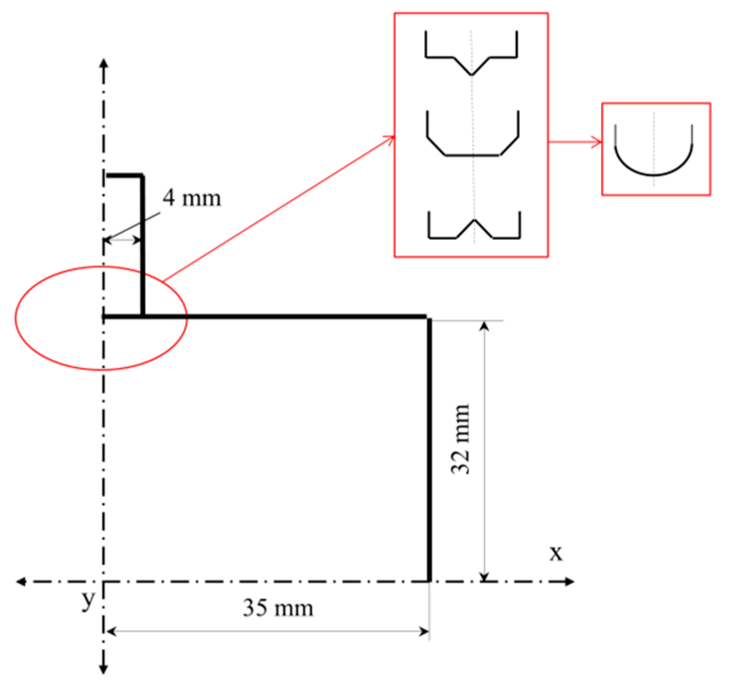
2. Materials and Methods

To optimise the forming process, understanding the workpiece deformation behaviour under different punch geometries is essential. The goal is to establish the analysis of different punches by the combination of flat and inclined geometries, case studies previously performed. Therefore, in this section, several FEM simulations with different punch geometries are carried out. In addition, an MUB model adaptation is introduced if necessary.

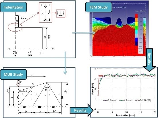
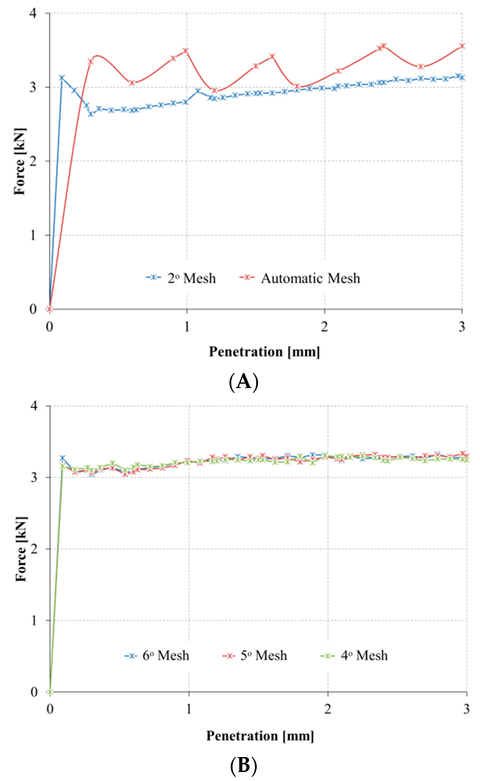
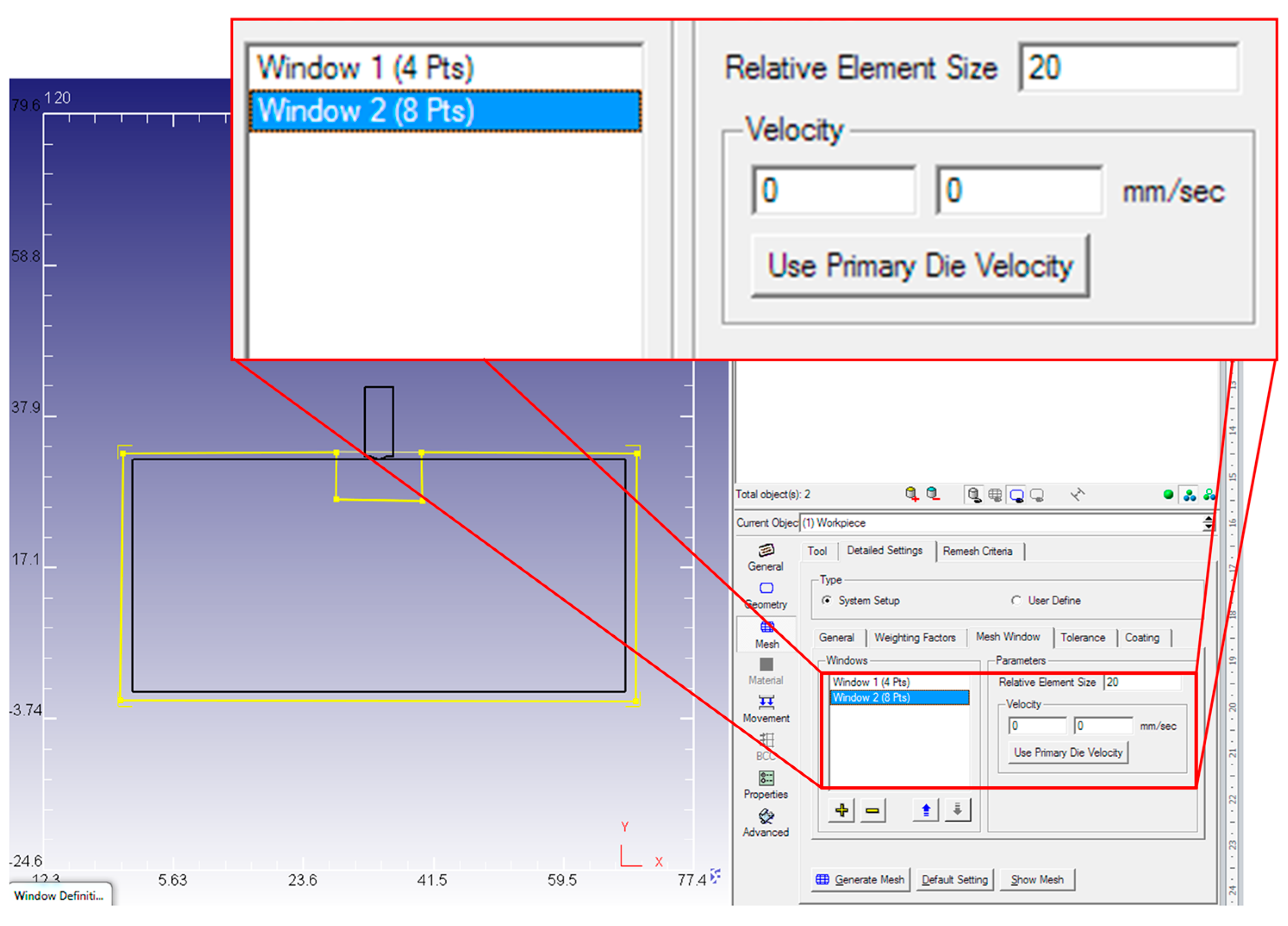
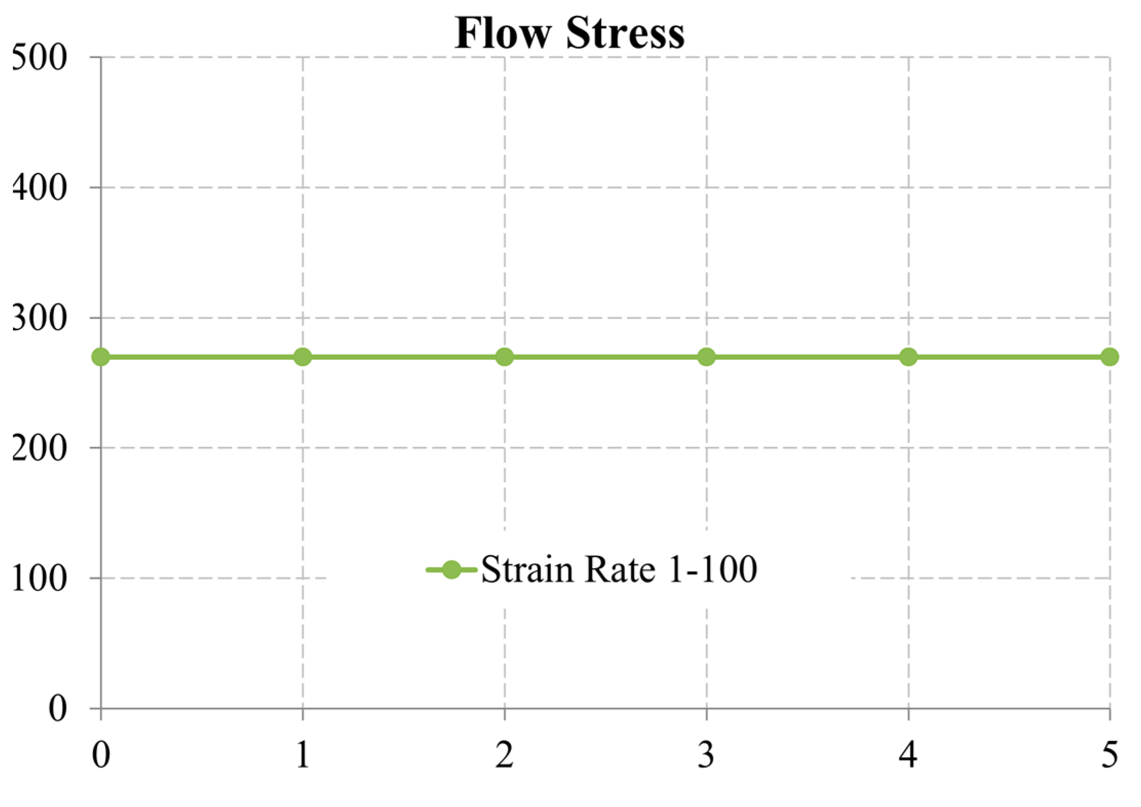
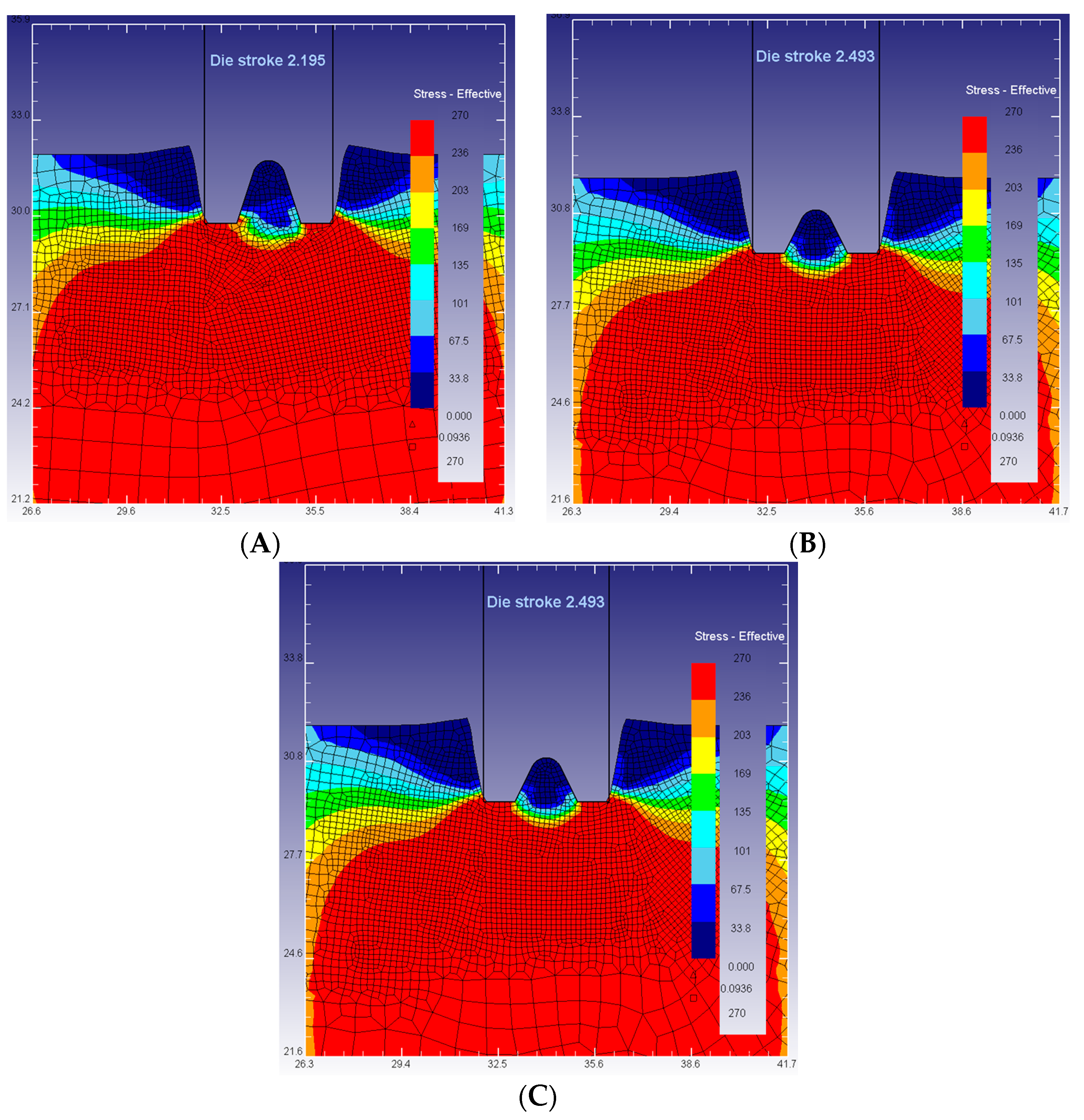
2.1. Numerical Analysis: Finite Element Method (FEM)

The problem consists of a one-stroke operation where a punch performs a single indentation in the workpiece, applying a 30% reduction. Different punch shapes are considered at the surface in contact with the workpiece. The displacement of the workpiece is partially restricted horizontally due to the vertical symmetry imposed. The dimensions and geometry of the workpiece are presented in Figure 3.
The workpiece material is A92024 (Unified Numbering System (UNS) designation, Scientific Forming Technologies Corporation, Columbus, OH, USA), cold worked without hardening effect. The simulation is contemplated under plain strain conditions taking the adhesion friction into account. Friction in bulk forming processes—like indentation or forging—has been deeply studied [22,23]. In forming processes where high pressure takes place, the adhesion friction offers a more precise approximation than the Coulomb model.
Due to the plain strain condition, software DEFORM 2D (Scientific Forming Technologies Corporation, version 8.1, Columbus, OH, USA, 2004) is chosen for the FEM analysis. Furthermore, working with 2D, the computational resolution times are lower than with 3D simulations.
The punch is considered a rigid object, modelled as a non-deformable material, and the workpiece a plastic object, modelled as a rigid-plastic material. Only half of the workpiece is implemented to reduce workload (Figure 3). Focusing resolution on simulation times and results accuracy, the mesh is implemented, taking advantage of mesh windows. This tool allows a division of the part studied, having higher density meshes—more elements per unit area/volume—where needed. Therefore, a higher density mesh window is placed at the workpiece part in contact with the punch and a second mesh window with a coarse density is placed for the remaining workpiece. Working with very high density mesh increases computational times. Consequently, in this case, the refined mesh is applied only to the deformation area, attempting to acquire the exact indentation shape. Although coarse FE meshes influences solutions’ accuracy, results are obtained in a reasonable time. Using the mesh window tool, we can reduce simulation times without sacrificing accuracy.
The relative element size relation between mesh windows is 1/20. That is to say, the elements of the second mesh are twenty times larger than the elements in the first mesh, having a total number of five thousand elements. The optimal mesh configuration is obtained from several simulations carried out until results repeatability is achieved (Figure 4). Along with the element size, velocity can be assigned to the window, making it possible to follow the punch throughout the entire penetration (Figure 5).
The material assigned from the database is UNS A92024, selecting the tabular data format as the flow stress law (Equation (8)). This method is recommended when the true behaviour of the material needs to be implemented. Figure 6 shows the material behaviour in this case study:
σ ¯ = σ ¯   ×   ( ϵ ¯ , ϵ ¯ ˙ , T )
where:
  • σ ¯ = Flow stress;
  • ϵ ¯ = Effective plastic strain;
  • ϵ ¯ ˙ = Effective strain rate;
  • T = Temperature.
Finally, the general simulation settings are shown in Table 1.
These conditions are maintained hereinafter for the different geometries considered (Figure 7).

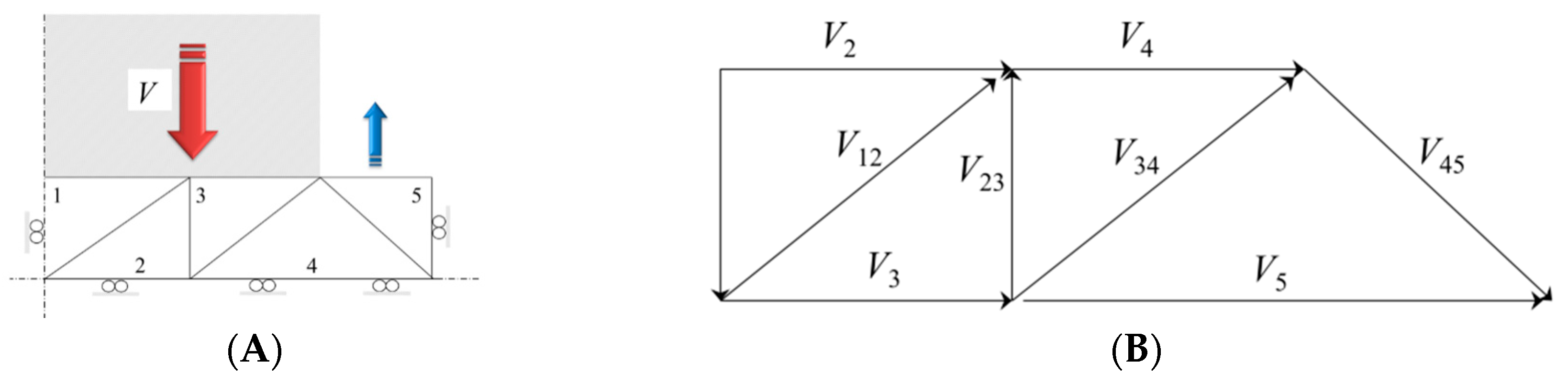
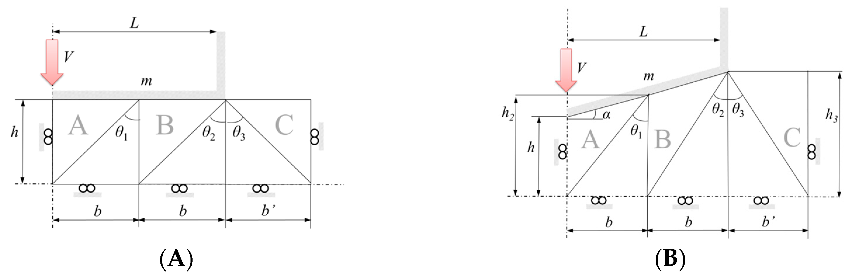
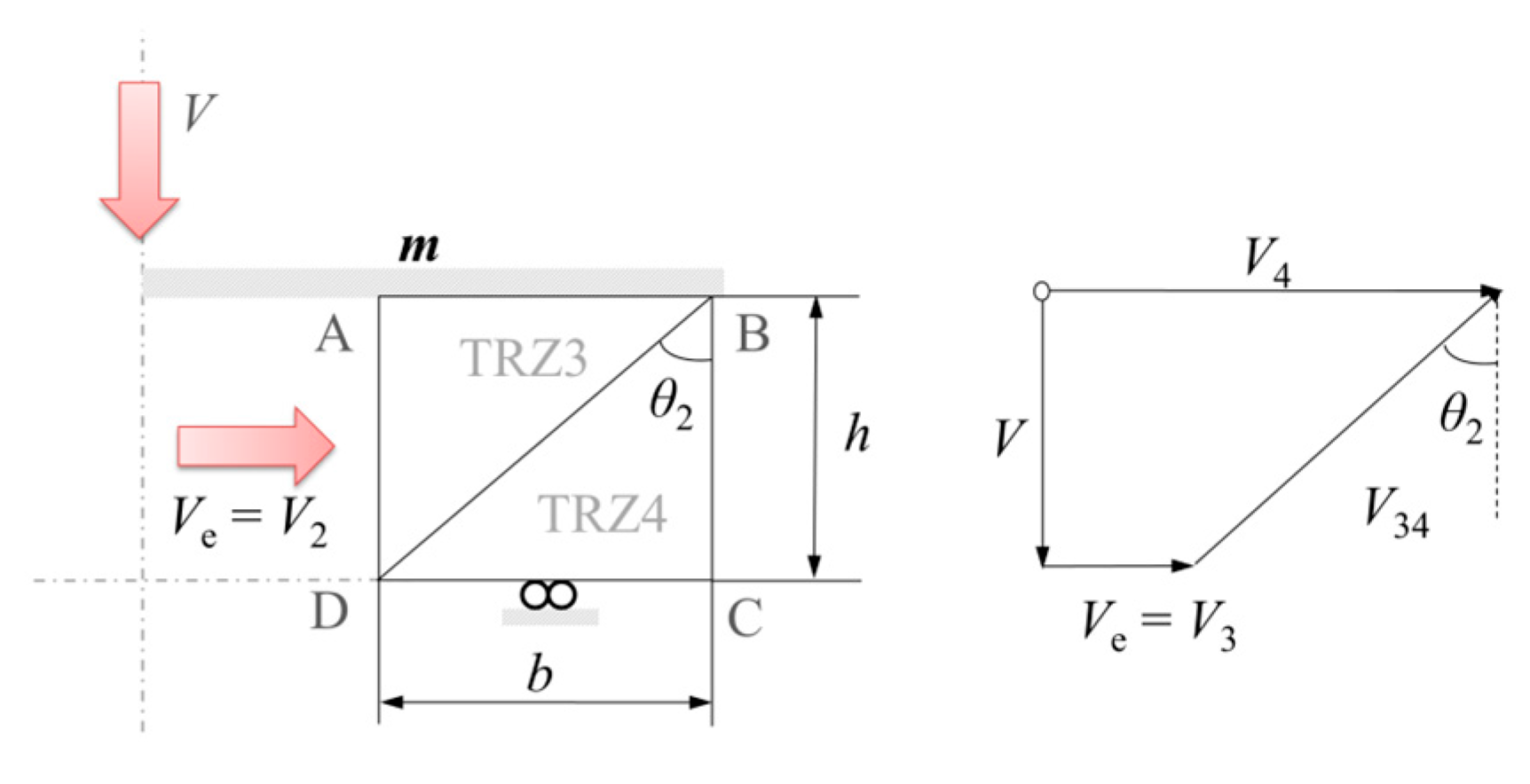
2.2. Analytical Analysis: Modular Upper Bound (MUB)

In previous investigations, the MUB models were developed for a flat punch (FP) and an inclined punch (IP) case (Figure 2) [19,20], showing that the new UBT model is not a geometrical-limited application. MUB is found to be an adaptive method of analysis that saves resolution time, having a simpler implementation than other methods. Now, in this paper, a flat-inclined punch combination is implemented, generating different shapes as seen in Figure 7. For these cases, FP + IP shows that the external part of the punch has a flat consideration and the central part has an inclined consideration, being IP + FP inversely. With these punches, diverse indentations are analysed, covering more applications and adapting the MUB model if necessary.
Knowing that the analysis is implemented with the plane strain hypothesis, after several simplifications, Equation (1) is expressed like:
S V T i   ×   v i   ×   d S v S D k   ×   v * d S D *
In addition, the value of the external forces per unit length can be expressed as follows:
d W d t d E d t = k   ×   s   ×   v *
where W is the external forces work and E is the internal dissipated energy per unit length. Likewise, working with a velocity field formed by straight lines, the next equation can be applied:
d W d t k   ×   s   ×   v *
It is possible to analyse each module independently working with the modular configuration. Figure 8 explains the middle module approach—module B—with its corresponding hodograph for an infinite FP case study. The resolution is shown in Equations (12)–(16).
Following Figure 8 diagram, Equation (11) can be expressed as follows:
p   ×   V   ×   b = k   ×   [ V e   ×   m   ×   A B ¯ + V 34   ×   D B ¯ + V 4   ×   C D ¯ ] ,
p   ×   b = k   ×   [ b 2   ×   m h + 1 h h 2 + b 2   ×   h h h 2 + b 2 + 2 b 2 h ]
( p 2 k ) MA = h 2 + b 2   ×   ( 1 + m ) 2   ×   b   ×   h
( p 2 k ) MB = h 2 + b 2   ×   ( 3 + m ) 2   ×   b   ×   h
( p 2 k ) MC = b 2 + b ' 2 + 2   ×   h 2 b   ×   h
where p is the sought pressure and b’ the external base of module C (MC). While the base of modules A and B are limited by the punch length, the external module can be considered as needed. In this case, the optimum b’ is provided from previous studies [19,20].
For an infinite inclined punch (IP) case study (Figure 2B), Equation (11) is expressed as:
p   ×   b = k   ×   [ b 2   ×   m h 2   ×   c o s α + 1 ( b h 2   ×   s e n α ) h 3 h 3 2 + b 2   ×   h 3 h 3 h 3 2 + b 2 + b   ×   ( b h 2   ×   c o s α + b h 3 ) ]
p/2k relation being for each module:
( p 2 k ) MA = 1 2 b   ×   [ h 2 2 + 2 b 2 h 2 ]
( p 2 k ) MB = 1 2 b   ×   [ b 2   ×   m h 2   ×   c o s α + ( b 2 + h 3 2 )   ×   ( 1 b h 2   ×   s i n α ) h 3 + b 2 h 3 + b 2 h 2   ×   c o s α ]
( p 2 k ) MC = 1 2 b   ×   [ b c o s α h 2 + b h 3 ]   ×   [ b + b ' 2 + 2 h 3 2 b ]
Once the modules are analysed separately, a weighted mean is applied to obtain the total contribution of p/2k (Equation (21)):
( p 2 k ) T = [ ( p 2 k ) MA   ×   b + ( p 2 k ) MB   ×   b + ( p 2 k ) MC   ×   b ' 2 b + b ' ]
The equations’ adequacy level is verified by comparing the analytical results with those obtained by FEM. The next section gives an introduction of the results obtained by the FEM analysis, having them doubly compared: first, with the ones obtained previously from the FP and IP study by another FEM analysis, and second, with MUB. An MUB model review will be considered if necessary.

3. Results and Discussion

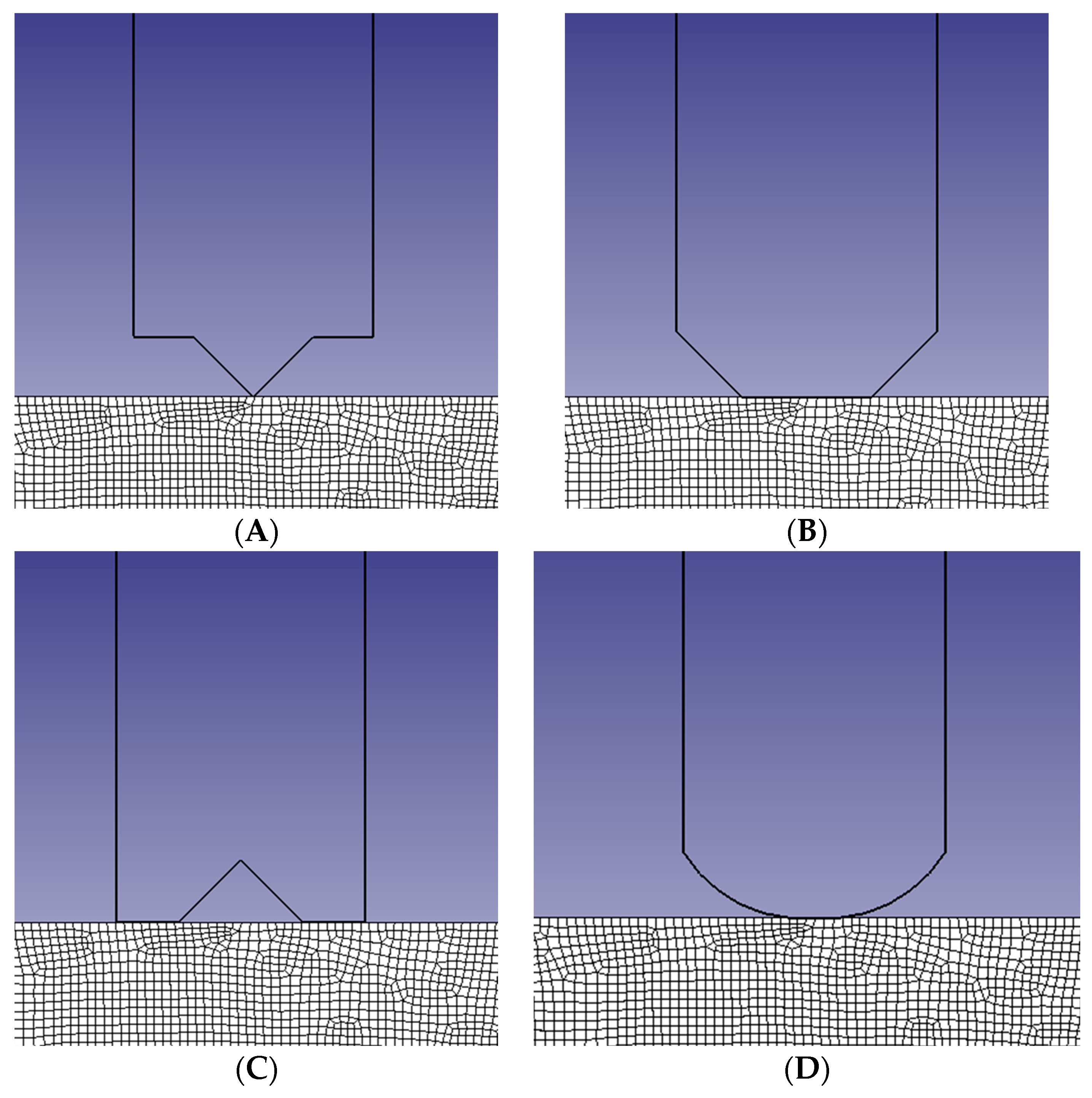
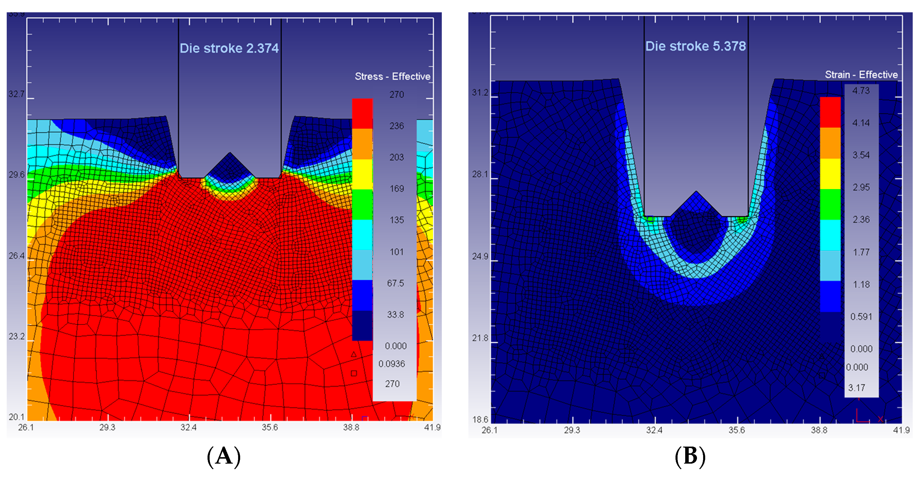
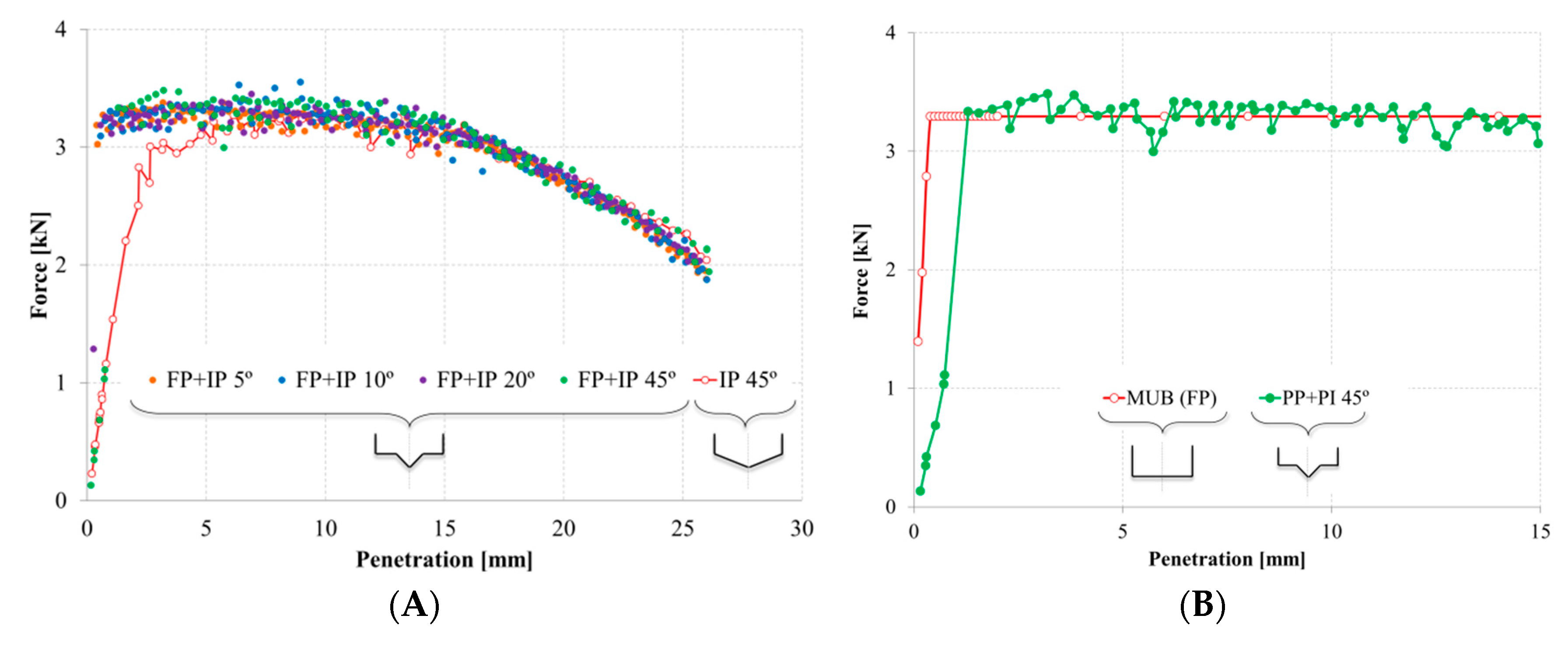
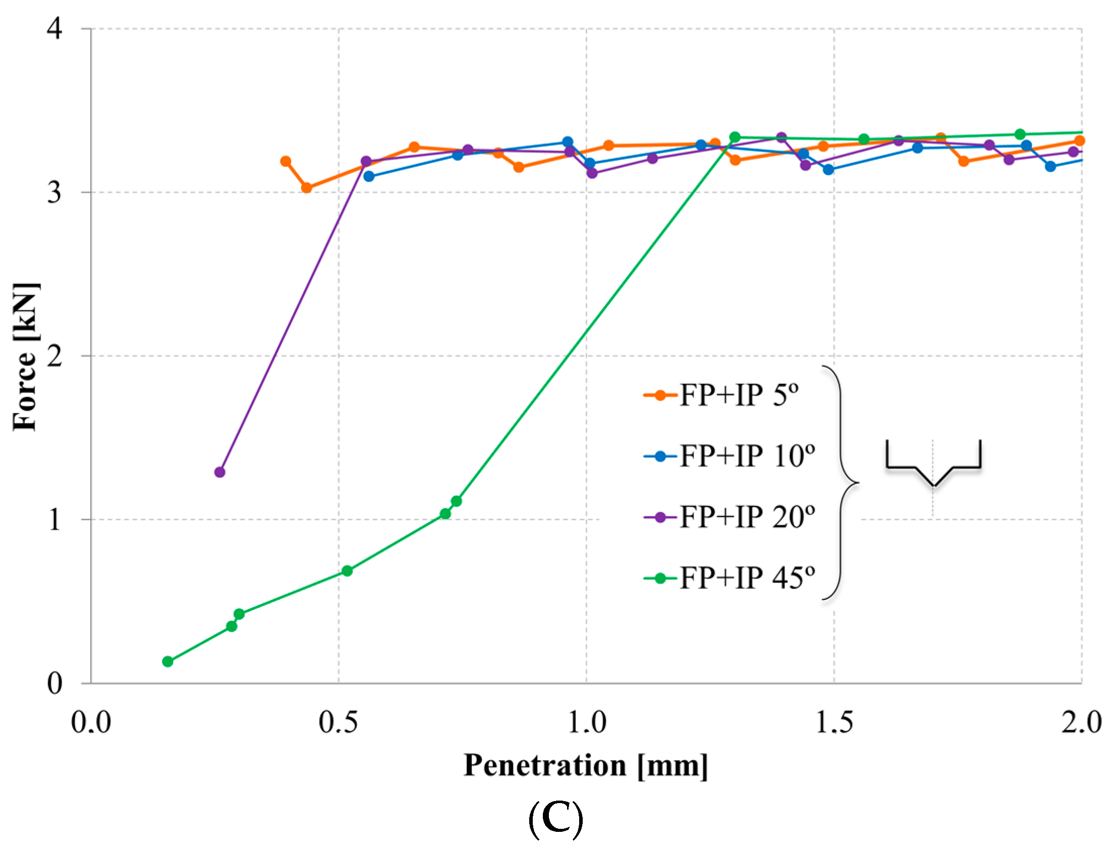
3.1. Geometry 1: Flat Punch (FP) + Inclined Punch (IP)

The first shape simulated is illustrated in Figure 7A, combining flat (FP) and inclined (IP) geometry (FP + IP). This punch presents an inclined central part where the inclination angle (α) can vary. In this paper, a 5°–45° angle variation is considered. In addition, the punch and the workpiece display a vertical symmetry.
Figure 9 shows that when there is a total contact of the punch surface with the workpiece, results tend to stabilize (Figure 9A), presenting a maximum force value. This also matches with the behaviour of MUB for FP (Figure 9B) and previously published trends [20].
In case the sharp ends of the punch have an influence on the results obtained, a simulation of the same geometry with rounded ends is implemented. The new results show the same progress as in Figure 9.
Noticing the sharp central zone of the punch, a new mesh study is suggested (Figure 10). The new mesh characteristics are represented in Table 2. Conversely to what was expected, the results with the refine mesh present more pick values. This problem could lie in the fact that the mesh was refined only for the central part of the punch, and, therefore, the mesh at the punch extremes shows distorted elements that could be affecting the final results with pick values. Thus, another simulation is solved taking into account the total punch surface.
New mesh is implemented assigning them the relations of 0.6/3/7/15. Therefore, now the results present a smoother evolution and slightly lower values than before (Figure 10A). However, these results agree with previous patterns. After the FEM analysis is carried out for geometry 1, it can be assumed that the final results are of the same order as the ones obtained from the simpler IP analysis. For this reason, the IP model is the optimum model for these geometry studies and the previous MUB model does not need to be redesigned.

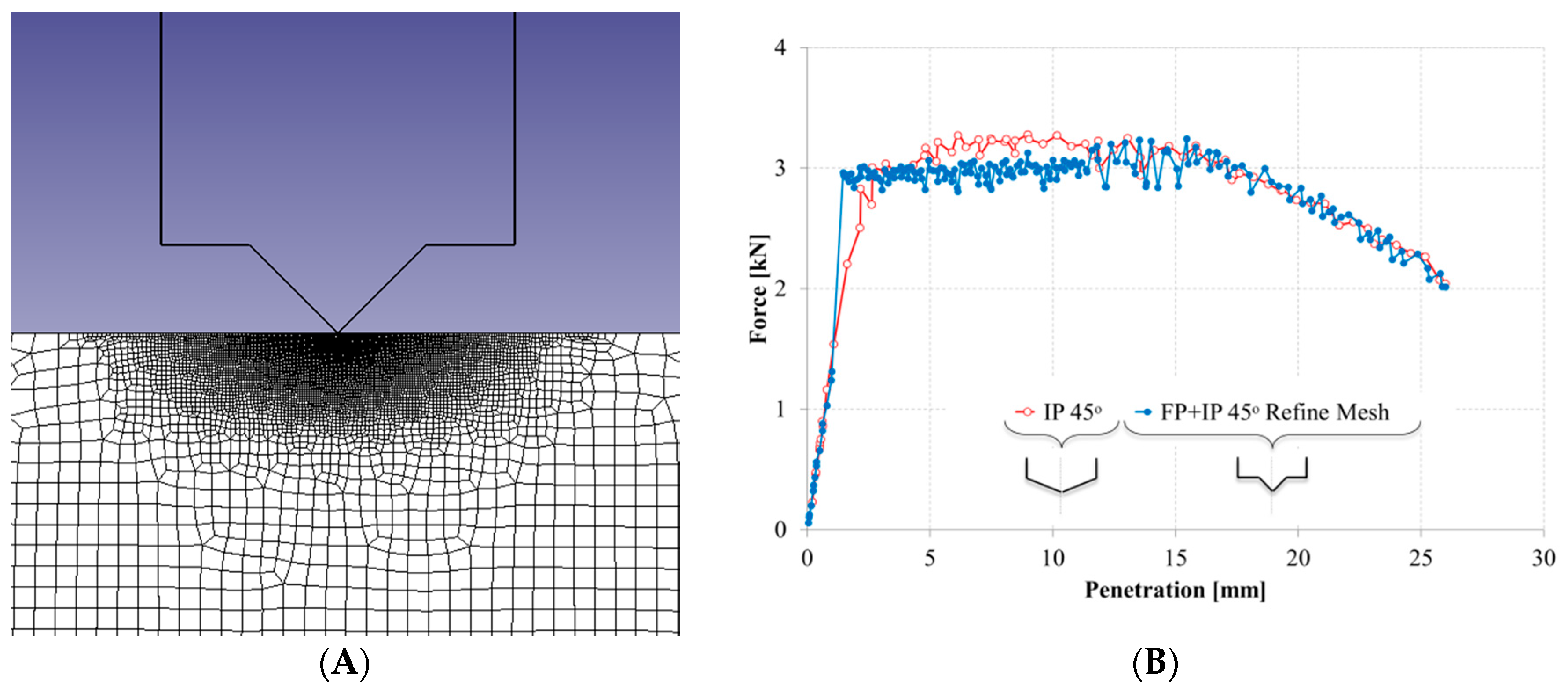
3.2. Geometry 2: IP + FP

The second geometry analysis is the one obtained from a combination of the same FP and IP but in the opposite order (IP + FP), as Figure 7B illustrates. The result comparison with the previous IP simulation can be seen in Figure 11. Again, the maximum force value is achieved with a total contact of the punch surface with the workpiece. In addition, this maximum force value is of the same order as the one in the IP case study.
Therefore, again, this specific geometry analysis can be simplified to an IP case, applying the explained MUB model for it.

3.3. Geometry 3: Inverted Punch

For this case, a punch with a middle cavity or nook is simulated. This punch represents an inverted form of the first geometry suggested for 45° (Figure 7C). This kind of geometry can be found, for example, in the manufacturing processes of gear discs [11].
In Figure 12, it can be appreciated how the punch nook is filled with the indented material. The material inside this cavity creates a solidary zone with the punch that does not suffer from deformation, helping the punch during penetration. This behaviour coincides with the definition of dead metal that can be found in the classic literature [24,25].
The results show that there is no significant disagreement with the ones obtained from prior geometries and case studies except for the initial stages of deformation, before the punch is filled. Although the maximum force achieved is the same, the results from these initial stages are slightly greater. Nevertheless, making a comparison with the results from the FP simulations, this variance is avoided. Thus, the MUB model for FP can be applied in order to approximate final results.
To ascertain how the cavity shape or dimensions affects the forces obtained, a sub-study of this geometry is considered. Several simulations with changes in the cavity depth—10%, 20% or 30% of the punch—are performed. Figure 13 shows the process evolution for different considerations and Figure 14 shows that, again, the maximum force obtained has the same trend as the other results. The dissimilarities only take place at the first stages, until the nook is filled.
The problem analysis considers that the total filling of the punch is pursued in the indentation process with these types of punches. Therefore, the problem can be analysed applying the FP MUB model, as shown in Figure 14B. It can be observed that the maximum force obtained is of the same range in MUB and FEM.

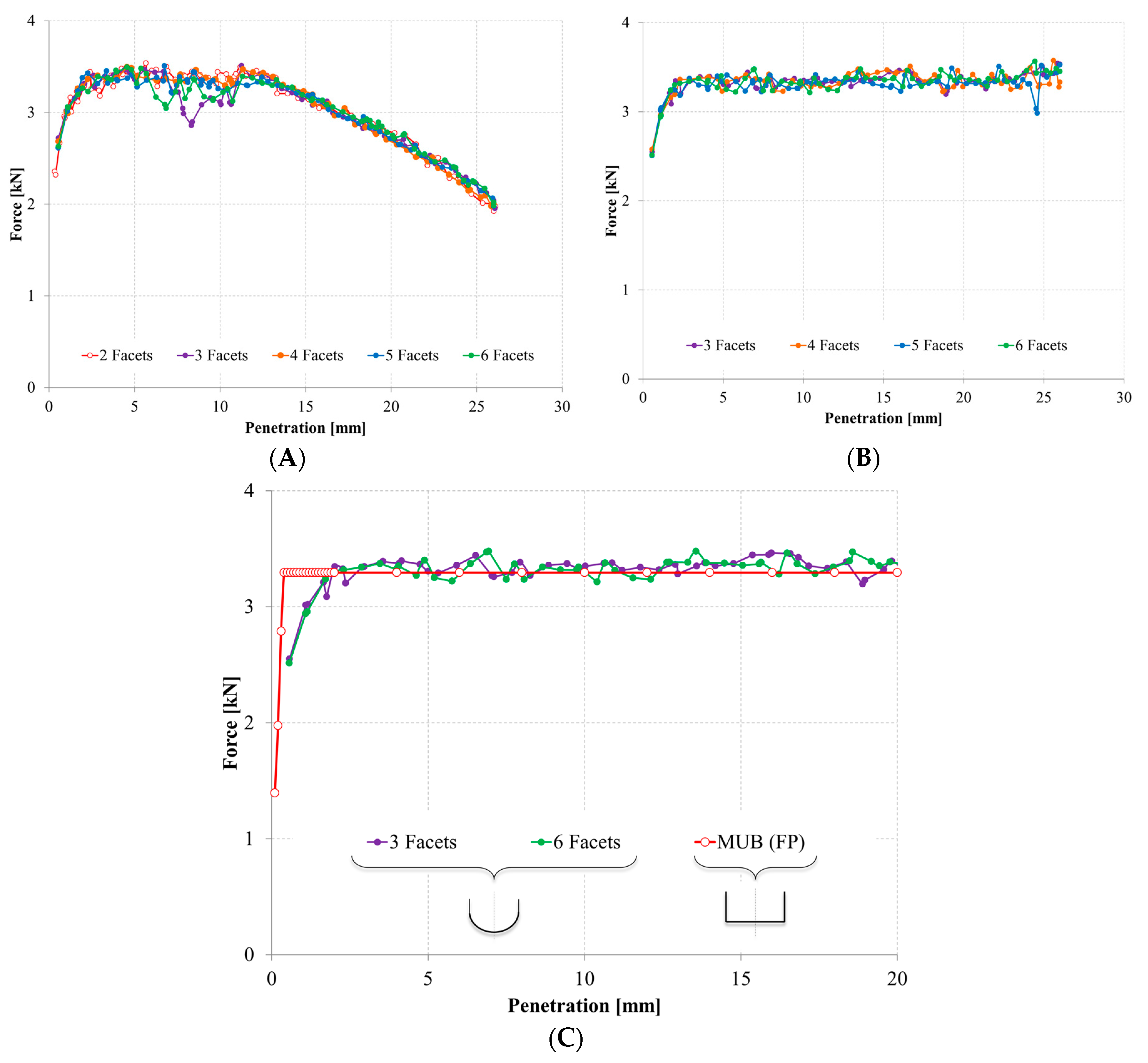
3.4. Geometry 4: Curved Punch

Finally, taking geometry 2 as the starting case (Figure 7D), more divisions or facets can be introduced as far as a curve geometry is approached (Figure 15). The evaluation of each case is implemented with FEM to observe the stress variation.
Results reveal close similarities in terms of strain in every sub-case, as the force/displacement graphic confirm (Figure 16A). Evolution changes in punches with three and six facets—between a 5 mm and a 10 mm penetration—are due mesh distortions in those stages. These deviations can be neglected given the analogy of the rest of the results obtained.
Knowing that the infinite phase is the one that plays an important role in this investigation, a closer analysis is worth performing. To this end, a higher workpiece was designed, establishing the infinite stage for a longer penetration. Figure 16B perfectly shows the likenesses highlighted between the different sub-cases simulated and Figure 16C the MUB approach. This last figure provides evidence that the FP MUB solution agrees well with the results obtained from the FEM analysis implemented, providing the maximum force value sought with less computational time and effort.

4. Conclusions

The main purpose of this study was to examine the influence of the punch geometry in indentation and validate MUB as a suitable method of analysis against other analysis methods, like FEM. Different punch geometries were implemented throughout these analysis procedures.
Based upon the numerical and analytical work carried out in this paper, the following conclusions were reached:
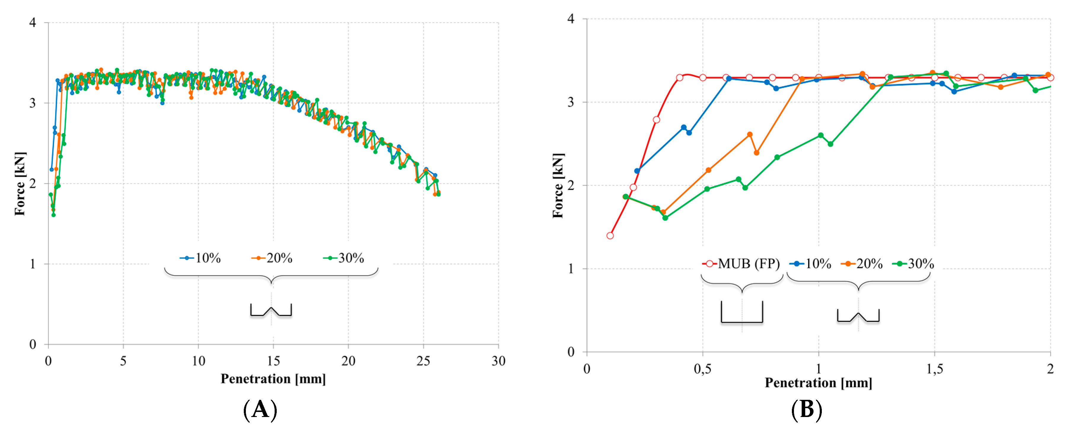
  • A general trend was observed. Working with deep indentations, punch geometries present low influence, always reaching a maximum force value when the punch surface has total contact with the workpiece indented, as demonstrated with FEM analysis and MUB.
  • By comparing results, it could be stated that the MUB developed method shows a good correlation with FEM results. The FEM and MUB solutions agree well with each other, being results in the same range.
  • On the one hand, to obtain a maximum effort value when a total contact of the punch surface is needed, the analysis of different punch geometries can be reduced to the application of the FP MUB model. On the other hand, in case a closer analysis of the deformations’ initial stages is wanted, the application of the IP MUB model provides a more accurate solution.
  • The evaluation of a curve punch was achieved by approximating the IP + FP geometry. The facets were increased until a curve geometry was obtained with six facets. The results obtained show similarities with the IP geometry and they also reach the same maximum force value.
  • Unlike the conventional UBT method and FEM analysis, MUB presents much simpler constitutive equations and relations. In addition, its modular configurations confer versatility, being able to better adapt to different shapes with less resolution time.
Therefore, MUB presents an easier application and resolution. It requires less calculation effort than the conventional UBT method and the analysis complexity does not increase aggregating more modules to the model. In addition, directly compared with FEM, MUB offers better computational efficiency, obtaining the same results with less fluctuation in their evolution, which makes result interpretation easier. The main disadvantage of FEM is that computational times are long—it could last minutes or hours depending on the analysis vs. seconds applying MUB—and coarse meshes are needed to solve problems in a reasonable time, which sacrifices accuracy.

Acknowledgment

The authors want to thank the University of Malaga–Andalucía Tech, International Campus of Excellence, for its financial support on this paper.

Author Contributions

Carolina Bermudo, Francisco Martín and Lorenzo Sevilla conceived and designed the experiments; Carolina Bermudo performed the experiments; Carolina Bermudo, Francisco Martín and Lorenzo Sevilla analyzed the data; Francisco J. Trujillo contributed in the analysis tools; Carolina Bermudo wrote the paper.

Conflicts of Interest

The authors declare no conflict of interest.

References

  1. Zhuang, W.; Hua, L.; Han, X.; Dong, L. Distribution of microstructure and Vickers hardness in spur bevel gear formed by cold rotary forging. Adv. Mech. Eng. 2014, 6, 1–13. [Google Scholar] [CrossRef]
  2. Nowak, J.; Madej, L.; Grosman, F.; Pietrzyk, M. Material flow analysis in the incremetal forging technology. Int. J. Mater. Form. 2010, 3, 931–934. [Google Scholar] [CrossRef]
  3. Tkocz, M.; Grosman, F. Application of incremental metal forming for production of aircraft integral panels. Solid State Phenom. 2014, 212, 243–246. [Google Scholar] [CrossRef]
  4. Grosman, F.; Madej, Ł.; Ziółkiewicz, S.; Nowak, J. Experimental and numerical investigation on development of new incremental forming process. J. Mater. Process. Technol. 2012, 212, 2200–2209. [Google Scholar] [CrossRef]
  5. Choi, S.; Na, K.H.; Kim, J.H. Upper-bound analysis of the rotary forging of a cylindrical billet. J. Mater. Process. Technol. 1997, 67, 78–82. [Google Scholar] [CrossRef]
  6. Gisbert, C.; Bernal, C.; Camacho, A.M. Improved analytical model for the calculation of forging forces during compression of bimetallic axial assemblies. Procedia Eng. 2015, 132, 298–305. [Google Scholar] [CrossRef]
  7. Bouffioux, C.; Eyckens, P.; Henrard, C.; Aerens, R.; Bael, A.; Sol, H.; Duflou, J.R.; Habraken, A.M. Identification of material parameters to predict single point incremental forming forces. Int. J. Mater. Form. 2008, 1, 1147–1150. [Google Scholar] [CrossRef]
  8. Camacho, A.M.; Marín, M.M.; Rubio, E.M.; Sebastián, M.A. Modeling strategies for efficient FE simulation of localised-incremental forging processes. AIP Conf. Proc. 2012, 1431, 725–732. [Google Scholar]
  9. Bernal, C.; Camacho, A.M.; Marín, M.; de Agustina, B. Methodology for the evaluation of 3D surface topography in multiple indentation processes. Int. J. Adv. Manuf. Technol. 2013, 69, 2091–2098. [Google Scholar] [CrossRef]
  10. Liu, Z.B.; Li, Y.L.; Daniel, W.J.T.B.; Meehan, P. Taguchi optimization of process parameters for forming time in incremental sheet forming process. Mater. Sci. Forum 2014, 773–774, 137–143. [Google Scholar] [CrossRef]
  11. Sieczkarek, P.; Isik, K.; Ben Khalifa, N.; Martins, P.A.F.; Tekkaya, A.E. Mechanics of sheet-bulk indentation. J. Mater. Process. Technol. 2014, 214, 2387–2394. [Google Scholar] [CrossRef]
  12. Song, Z.; Komvopoulos, K. Elastic-plastic spherical indentation: Deformation regimes, evolution of plasticity, and hardening effect. Mech. Mater. 2013, 61, 91–100. [Google Scholar] [CrossRef]
  13. Kukureka, S.N.; Craggs, G.; Ward, I.M. Analysis and modelling of the die drawing of polymers. J. Mater. Sci. 1992, 27, 3379–3388. [Google Scholar] [CrossRef]
  14. Moon, Y.H.; van Tyne, C.J.; Gordon, W.A. An upper bound analysis of a process-induced side-surface defect in forgings: Part 1: The velocity fields and power terms. J. Mater. Process. Technol. 2000, 99, 169–178. [Google Scholar] [CrossRef]
  15. Medeiros, N.; Moreira, L.P.; Bressan, J.D.; Lins, J.F.C.; Gouvêa, J.P. Upper-bound sensitivity analysis of the ECAE process. Mater. Sci. Eng. A 2010, 527, 2831–2844. [Google Scholar] [CrossRef]
  16. Parvizi, A.; Abrinia, K. A Two dimensional upper bound analysis of the ring rolling process with experimental and FEM verifications. Int. J. Mech. Sci. 2014, 79, 176–181. [Google Scholar] [CrossRef]
  17. Johnson, W.; Mellor, P.P.B. Engineering Plasticity; Ellis Horwood Limited: Chichester, UK, 1983. [Google Scholar]
  18. Kudo, H. An upper-bound approach to plane-strain forging and extrusion-I. Int. J. Mech. Sci. 1960, 1, 57–83. [Google Scholar] [CrossRef]
  19. Bermudo, C.; Martín, F.; Sevilla, L.; Martín, M.J. Experimental validation of the new modular application of the upper bound theorem in indentation. PLoS ONE 2015, 10, e0122790. [Google Scholar] [CrossRef] [PubMed]
  20. Bermudo, C.; Martín, F.; Sevilla, L. Application of the upper bound theorem to indentation processes with tilted punch by means of modular model. Procedia Eng. 2015, 132, 274–281. [Google Scholar] [CrossRef]
  21. Martín, F.; Camacho, A.M.; Domingo, R.; Sevilla, L. Modular procedure to improve the application of the upper-bound theorem in forging. Mater. Manuf. Process. 2013, 28, 282–286. [Google Scholar] [CrossRef]
  22. Fereshteh-Saniee, F.; Pillinger, I.; Hartley, P. Friction modelling for the physical simulation of the bulk metal forming processes. J. Mater. Process. Technol. 2004, 153–154, 151–156. [Google Scholar] [CrossRef]
  23. Kačmarčik, I.; Movrin, D.; Ivanišević, A. One contribution to the friction investigation in bulk metal forming. J. Technol. Plast. 2011, 36, 35–48. [Google Scholar] [CrossRef]
  24. Hill, R. The Mathematical Theory of Plasticity; Oxford Classic Texts in the Physical Sciences: Oxford, UK, 1998. [Google Scholar]
  25. Backofen, W.A. Deformation Processing; Addison-Wesley Educational Publishers Inc.: Boston, MA, USA, 1972. [Google Scholar]
Figure 1. Upper Bound Theorem (UBT) Indentation Analysis. Triangular Rigid Zone (TRZ) distribution (A) and Kinematically Admissible Velocity Field (KAVF) analysis (B).
Applsci 06 00203 g001
Figure 2. Flat (A) and inclined (B) punch Modular Upper Bound (MUB) application. h is the height, b/b’ is the base and θi is the angle of the modules, m is the friction coefficient, α is the angle and L is the length of the punch, represented each module with a letter.
Applsci 06 00203 g002
Figure 3. Dimensions and geometries (red frame) of the indentation process simulated.
Applsci 06 00203 g003
Figure 4. Mesh optimization study. Initial stage (A) and optimized mesh (B).
Applsci 06 00203 g004
Figure 5. Mesh window display.
Applsci 06 00203 g005
Figure 6. Material flow law.
Applsci 06 00203 g006
Figure 7. Geometries studied. Flat punch (FP) + inclined punch (IP) (A); IP + FP (B); inverted punch (C) and curve punch (D).
Applsci 06 00203 g007
Figure 8. Module B (MB) approach.
Applsci 06 00203 g008
Figure 9. FP + IP simulation. Results obtained for different α compared with result from IP simulation (A); FP + IP and MUB for FP comparison (B) and first deformation stage details (C).
Applsci 06 00203 g009aApplsci 06 00203 g009b
Figure 10. Refined mesh implementation (A) and results (B).
Applsci 06 00203 g010
Figure 11. IP + FP study.
Applsci 06 00203 g011
Figure 12. Geometry 3 analysis. Strain (A) and stress (B) during deformation.
Applsci 06 00203 g012
Figure 13. Nook study: 10% (A); 20% (B); and 30% (C).
Applsci 06 00203 g013
Figure 14. Geometry 4 results (A) and first deformation stage details and comparison with MUB (B).
Applsci 06 00203 g014
Figure 15. Curve punch approximation with three (A) and six (B) facets.
Applsci 06 00203 g015
Figure 16. Geometry 4 results (A); detail (B); and MUB approach (C).
Applsci 06 00203 g016
Table 1. General simulation settings.
Simulation SettingsValue
Number of Simulation Steps100
Step Increment to save5
With equal die displacement0.26 (mm)
Remesh maximum step increment3
Table 2. New mesh implemented.
Mesh SettingsValue
Number of Elements10,000
Mesh Windows4
Mesh Windows Relation0.2/2/4/20

