Article

Biaxial-Type Concentrated Solar Tracking System with a Fresnel Lens for Solar-Thermal Applications

Department of Mechanical Engineering, National Kaohsiung University of Applied Sciences, Kaohsiung 80778, Taiwan
*
Authors to whom correspondence should be addressed.
Appl. Sci. 2016, 6(4), 115; https://doi.org/10.3390/app6040115
Submission received: 28 December 2015 / Revised: 8 April 2016 / Accepted: 11 April 2016 / Published: 20 April 2016

Abstract

:
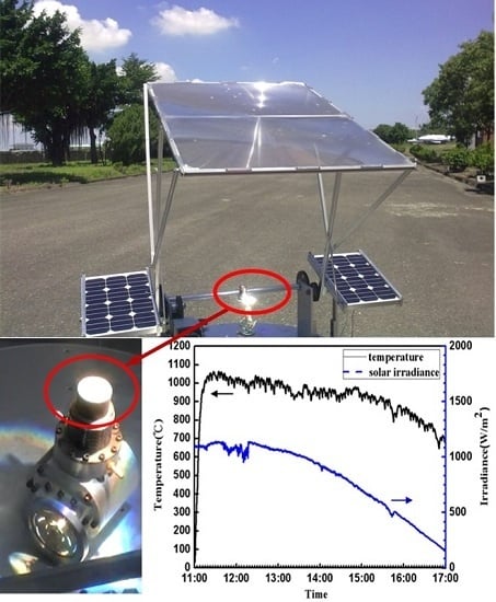
In this paper, an electromechanical, biaxial-type concentrated solar tracking system was designed for solar-thermal applications. In our tracking system, the sunlight was concentrated by the microstructure of Fresnel lens to the heating head of the Stirling engine and two solar cells were installed to provide the power for tracking system operation. In order to obtain the maximum sun power, the tracking system traces the sun with the altitude-azimuth biaxial tracing method and accurately maintains the sun’s radiation perpendicular to the plane of the heating head. The results indicated that the position of heating head is an important factor for power collection. If the sunlight can be concentrated to completely cover the heating head with small heat loss, we can obtain the maximum temperature of the heating head of the Stirling engine. Therefore, the temperature of heating head can be higher than 1000 °C in our experiment on a sunny day. Moreover, the results also revealed that the temperature decrease of the heating head is less than the power decrease of solar irradiation because of the latent heat of copper and the small heat loss from the heating head.

Graphical Abstract

1. Introduction

The growth of technology and the economy is heavily dependent on energy consumption and the demand for energy is increasing steadily every year. Environmental issues such as global warming and eco-friendliness have begun to attract attention in mainstream society. In addition, the consumption of fossil fuels also seriously affects our global environment; therefore, seeking other, environmentally friendly energy resources has become a worldwide priority. Solar energy, due to its green nature, and its easy acquisition at low cost, has demonstrated great potential as one of the top clean energy sources. According to a marketing report from the US marketing research and analysis company, BCC Research, the global markets for industrial and utility solar thermal technologies amounted to $929 million in 2008, which increased further to $3.7 billion in 2009 [1]. Therefore, the market for solar energy has great future potential.
To date, many countries have devoted efforts and resources to Stirling engine research for varying applications such as national defense, power generation, and aerospace [2]. Waste-heat [3,4], solar [5,6,7], biomass [8], low-temperature [9], and small Stirling engine systems [10,11] are examples of new power generation applications. Among these power systems, the solar Stirling engine is the most promising technology. The solar Stirling engine uses a parabolic reflector as the main heating element. The engine is installed at the base of the optical tracker with a rotational mechanism where the parabolic reflector is connected. This rotation/reflector subassembly is then assembled with engine, heating head, and power generation system to form the complete solar power system. The parabolic reflector focuses and projects the sunlight onto the surface of the heating head to drive the Stirling engine to generate electricity. In 2008, U.S. SES, Inc. and Sandia National Laboratories co-developed a Stirling solar dish collector power system, the Suncatcher [12]. The power generated from this system is 5–25 kW and the system operation temperature is 750 °C with energy efficiency of 29.4%. Infinia, Inc. [13] built a small dish Stirling generator, the Infinia Solar System, which was the size of a television satellite receiver. The system can generate 3 kW of power with 30% efficiency. These improvements in power generation techniques heavily depend on the sunlight tracking technology. Therefore, this study explored the effect of the focal point position of the focused sunlight to the heating surface area on the heating head. In addition, we are hoping it can also be applied to the development of future heating head modules.
The tracking approach and the system structure for the solar tracking system need to be compatible. Different tracking structure requires different tracking approaches. Generally, the two major solar tracking systems [14] are altitude-azimuth with biaxial rotation and west eastern-south northern with individual axis rotation. The advantages of the altitude-azimuth system are its wide rotation angle for the azimuth and less interference during tracking. This mechanism can also be used at broader regions on earth. However, it is more challenging to prepare the control algorithm for tracing the trajectory of the sun. For the solar tracking mechanism, passive and active tracing are the two major control approaches. The difference between them is mainly due to the use of electrical energy and the control program. The passive system uses passive components or physical/mechanical changes of the materials to change the structure of the tracking mechanism for sunlight tracking. However, the active control mechanism needs motor, control IC, tracking program, and sensing elements for tracking the position of the sun [15,16,17,18,19]. Chin et al. [20] designed an active single axis solar tracker with two light-dependent resistor (LDR) sensors that are located on the surface of the photovoltaic (PV) panel. The proposed control structure provides the flexibility to accommodate different weather conditions, and the system will be in “sleep” mode when night falls to prevent unnecessary energy loss. Clifford and Eastwood [21] used aluminum/steel bimetallic strips and viscous dampers to design the passive solar tracker. Their system allows efficiencies of up to 23% beyond that of fixed panels. In addition, Tripanagnostopoulos et al. [22] emphasized that Fresnel lenses were suitable for solar radiation concentration with lower volume and weight, smaller focal length and lower cost, compared to the thick ordinary lenses. It was found that the collection of 60%–80% of the transmitted solar radiation through the Fresnel lenses on linear absorbers leaves the remaining amount to be distributed in the interior space for illumination and thermal building needs. Xie et al. [23] also indicated that Fresnel lenses could be combined with thermal, photovoltaic, or hybrid-type photovoltaic/thermal absorbers to collect and extract concentrated solar radiation in the form of heat, electricity or both. By using thermal absorbers and for low operating temperature, efficiency of about 50% could be achieved, and, by considering photovoltaics, satisfactory electrical output could be obtained. Therefore, a biaxial-type concentrated solar tracking system with Fresnel lens, which was designed for Stirling engine application, was developed in this paper.

2. Experimental Methods and Apparatus

The altitude-azimuth biaxial-type concentrated solar tracking system as shown in Figure 1 in this study contains the following sub-systems: (i) solar cells and battery; (ii) control system; (iii) structure mechanism; and (iv) Fresnel lens module.
In order to track the sun trajectory accurately, we use the following Equation (1) as the sun tracking method in our experiment. In this equation, the altitude and azimuth trajectory formula use the hour angle (H) and declination (δ) in the sun-tracking formula by Chong and Wong [24]. The horizontal coordinate is very convenient to define the sun position for prerequisite initial position of the solar tracker. The altitude and azimuth of sun can be measured through Equation (1). If the angles difference (Δα, Δβ) is greater than the stepping motor step angle, the microprocessor will send a signal to the motor driver to actuate the solar tracker.
α = sin 1 ( sin φ · sin δ + cos φ · cos δ · cos H )
β = π cos 1 ( sin α · sin φ sin δ cos α · cos φ ) , when   H 0
If   δ φ , β = cos 1 ( sin α · sin φ sin δ cos α · cos φ ) π , when   H > 0 or   β = π + cos 1 ( sin α · sin φ sin δ cos α · cos φ ) , when   H > 0
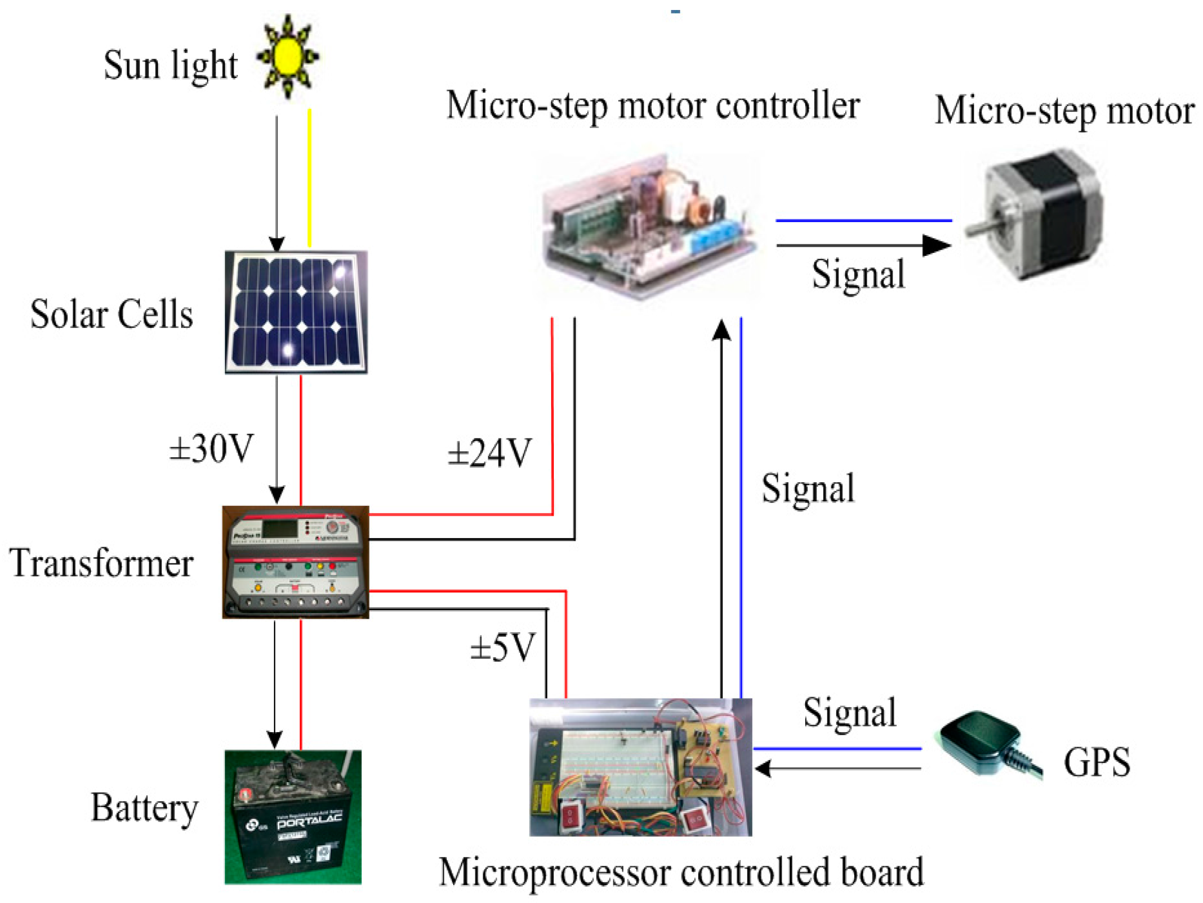
The tracking system used in this study belongs to the concentrated solar type of structure. This system uses solar cells installed on both sides of the solar tracking system to convert the solar power and store the power in its battery. The battery storage energy from these two solar cells can supply themicroprocessor power sources (AT89S52), GPS (SEN10752P), and two-step motors (TS3630N1210E3) (TAMAGAWA SEIKI CO., LTD, Matsusaka, Japan). Firstly, we use GPS to determine the tracking system location and then use the microprocessor (following Equations (1)–(3)) to control these two motors to rotate the azimuth angle and altitude angle to trace the sunlight, respectively. Besides, in our concentrated tracking system, the sunlight was concentrated by the microstructure of the Fresnel lens (area 1.3 m × 0.9 m) to the heating head of the Stirling engine. The system block diagram is shown in Figure 2.
The focal length of the selected Fresnel lens is defined in its specification. When the sunlight is focused through the lens, it forms a focal area on the heating head of the Stirling engine. In this experiment the position of the heating head was moved to obtain the effect of the size of the focal point on the temperature change of the heating head at varying heating times. The function of the heating head can absorb external heat and supply this thermal energy to the gas inside the Stirling engine. Therefore, the materials of the heating head must have high thermal conductivity and be able to withstand large temperature changes (600 °C–1200 °C).
In order to track the sun stability, the solar tracker needs to have sufficient mechanical strength and be suitable for machining operations. First, stainless steel, SUS304, was selected and the dimensions of the collector structure were unified for later side-by-side performance comparison. To reduce the weight, the main structure for the tracking system was made of aluminum alloy. The stepper motors, worm gears, and gear reducer were used to drive the overall tracking mechanism. Without an external power source, the on-board solar cell panels arranged on the side of the solar tracker converted the solar energy and then stored this energy in the battery. We also added the ProStar 30 solar charger controller to protect the battery from overcharging and provide electronic protection. In the meantime, the solar panel also supplied power to the motors and the control tracking system, as shown in Figure 2. The tracking control system has both manual and automatic modes. The control algorithm was uploaded to the micro-controller. A switch was integrated in the circuit to control the manual mode on demand to help to achieve quick system debugging. The program of the auto-model can adapt to different time zones and geographical locations based on the coordinate system of celestial bodies to simulate the trace of the sun. This control algorithm was very useful for the purpose of long-term, un-manned solar trace tracking.
In addition, since focused sunlight is extremely bright, for ease to interpret the change of focal point, a filter was added for observation. To expand the magnitude of the temperature curve change in order to facilitate the determination, the heating head was not wrapped with thermal insulation cotton. The interval of the tracking time was set as constant and the temperature data were stabilized to be compared from different testing conditions. Moreover, a copper heating head with better thermal conductivity was used to replace the steel heating head. This replacement was evaluated by eliminating the effect of the daily sunlight change. The result of this experiment yields the feasibility of the current heating head design and future improvement directions.

3. Results and Discussions

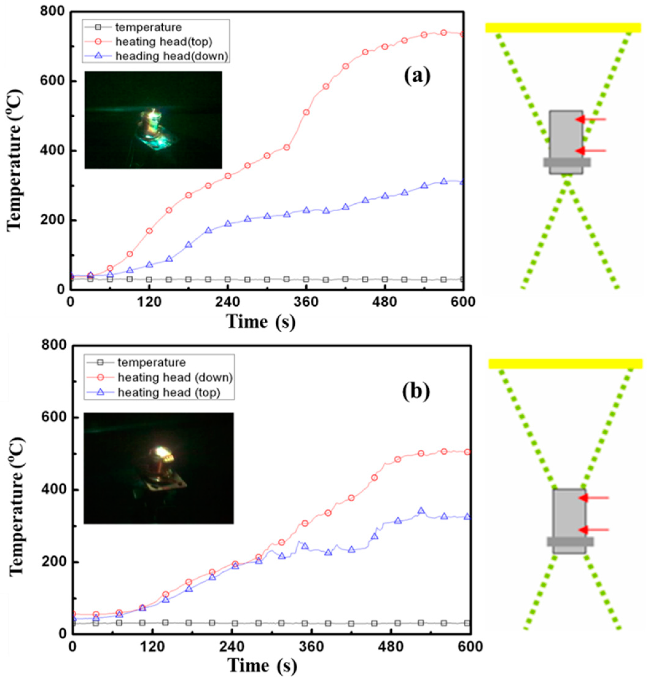
Figure 3 shows the temperature profile of the heating head with solar tracking. In Figure 3a, with light focused on the bottom of the heating head, the temperature began to rise rapidly because the sunlight irradiation covered the largest area of the heating head. In this condition, the heat loss of the heating head is very small and it will cause a larger initial slope of temperature profile. As time goes on, the focal point began to shift away from the heating head and the slope of the curve became less steep. Soon after a re-tracking of the trace of the sun by the solar tracker, the temperature rose quickly again. Then the slope of the temperature curve became stable because of the balance of heat loss of the heating head and heating source from the sunlight and the final stable temperature can reach 718 °C. Comparing the temperature curves for both the upper and lower surfaces of the heating head, it can be seen that the higher temperatures are on the top of the heating head. In addition, since the largest areas of the top surface of the heating head are heated by the sunlight, due to the different heat dissipation rates at other regions of the heating head, there was a temperature difference between the top and the bottom surfaces. In Figure 3b, with light focused on the top of the heating head, the temperature rises slowly because there is less heating area for the sunlight. The heat loss area of the heating head is very large so that the stable temperature only reaches 523 °C. This is because the operating principle for the Stirling engines depends on the temperature difference between hot and cold ends of the engine to produce work. Therefore, since the goal of the current system is to obtain a maximum temperature difference, having focal point projects covering the whole heating head surface is a better method than being located exactly on top of the heating head surface. Therefore, thermal insulation cotton wrapped around the engine body to prevent heat dissipation is a good method. Moreover, the slope of the temperature curve also depends on the material of the heating head. Since thermal conductivity of the material affects the speed of temperature change, when a higher thermal conductivity material is used, temperature will increase quickly with sunlight heating. However, when the focal point is shifted, heat dissipates sooner and the temperature also drops faster. In summary, the control accuracy of the focal point position, the tracking time interval, the material selection of the heating head and the design of the heating head all affect the efficiency of the temperature rise.
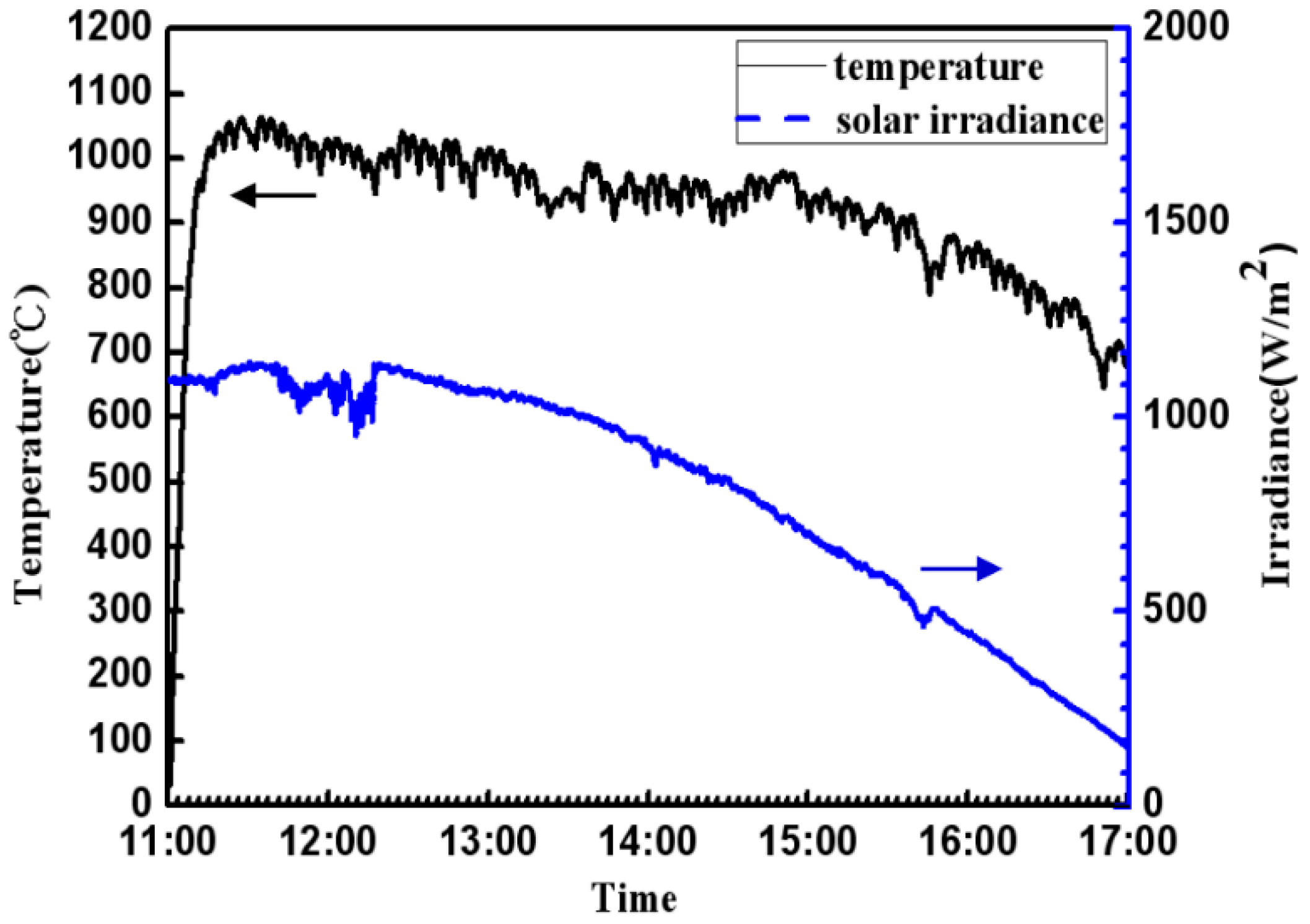
Although the theoretical efficiency of solar heating power with Stirling engine is higher than high-concentrating photovoltaic (HCPV), it may be limited by the accuracy requirement for the focus control and needs a frequently tracking operation to make sure the focus of solar power can be gathered on the engine heating head. Therefore, the accuracy of the solar tracking system is very important for solar heating application. In our experiment, because the thermal conductivity of copper is superior to steel, a copper heating head was applied to enhance the heating system. As shown in Figure 4, the temperature profile of the copper heating head shows the same trend as the solar irradiation measured directly from the sunlight by pyrheliometer. The heating head reaches its maximum temperature over 1000 °C. In the temperature profile as shown in Figure 4, the small temperature fluctuation is due to the shifting interval from the tracking system. In addition, in the afternoon around 16:00–17:00, when the decrease of solar irradiation is only about 80% compared to noon time, the decrease in the temperature curve is only approximately 35% because the heating head was covered by sunlight with small heat loss and the latent heat of copper heating head itself both decrease the temperature drop of the heating head. Hence, the temperature still maintained at a relatively higher temperature of around 650 °C even when the ambient solar irradiation is small.
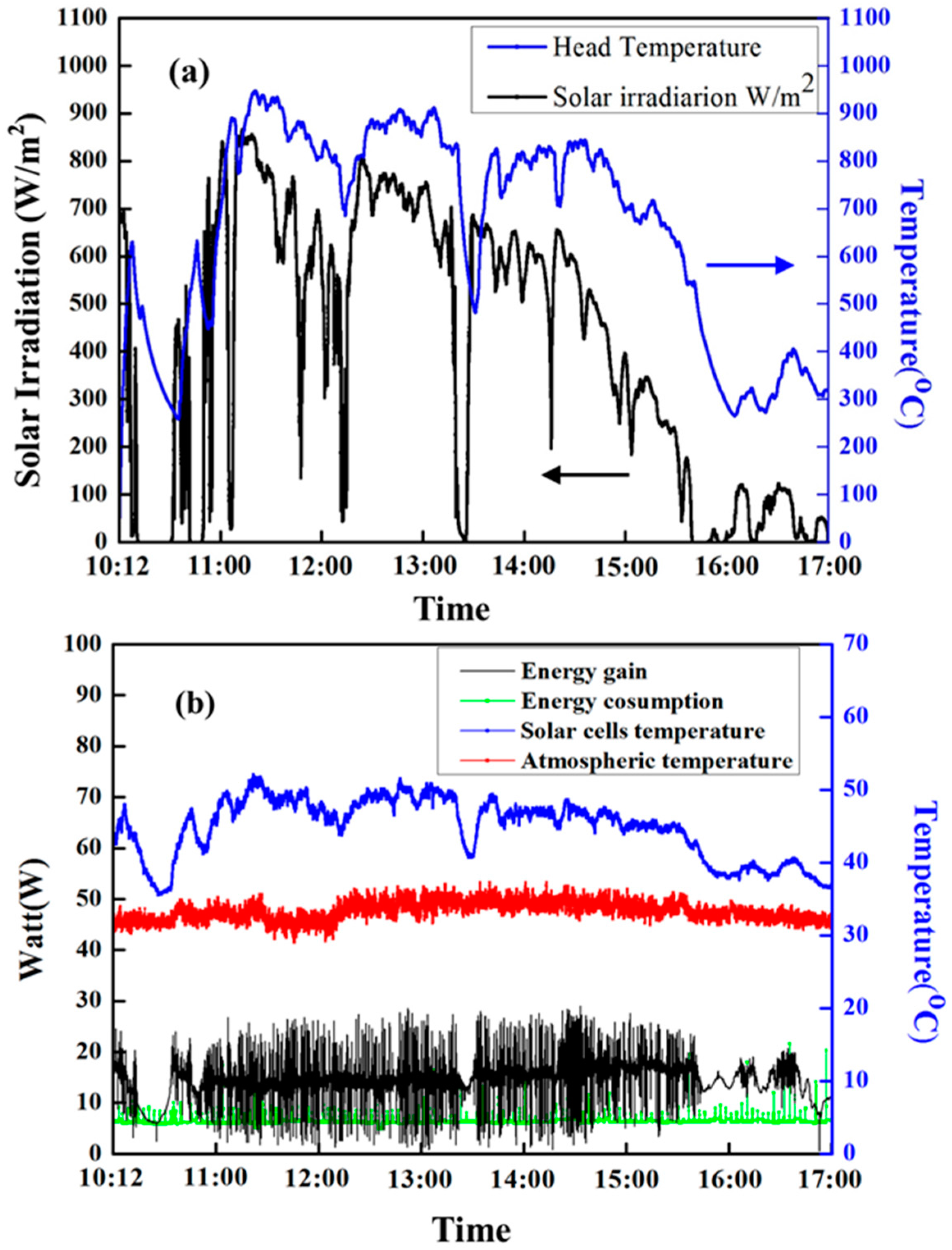
Figure 5a presented the relationship between heating head temperature and solar irradiation in summer on June 22, 2013. The heating head temperature is very similar and follows the incident solar irradiation because the power of solar irradiation was absorbed by the copper heating head. However, the temperature response of the heating head is clearly slower than the incident solar irradiation. The reason for this is due to the thermal insulation cotton and latent heat of the copper heating head. The temperature of the copper heating head will increase after the incident power of solar irradiation so that the temperature of the heating head has the some response delay as the solar irradiation. Therefore, for the same reason, the profile of the heating head temperature is smoother than the profile of solar irradiation. Besides, Figure 5b shows the energy gain by solar cell module, total energy consumption of the solar tracker system, the temperature profile of the solar cells and the ambient temperature profile on the same day. In this figure, energy consumption is derived from the operation of the motors. In our solar system, the two tracking motors are operated every four minutes. Therefore, the energy loss is about 6.5 W as the motor is resting and because the energy loss will increase immediately as the motor is tracking. This is why the energy consumption curve has intermittent pluses during a one-day test. Besides, the average energy gain from the two solar cells arranged on both sides of the solar tracker is related to the irradiation from the sunlight. In general, the average energy gain from the solar cells module is about 18.3 W from 10:46 to 15:35 and then it decreases with the decrease of solar irradiation because there are clouds obscuring the solar light after 15:35. The solar irradiation and energy gain from solar cells also shows the same trend. In Figure 5, we also measure the temperature of solar cells and the energy gain from solar cells which is independent of the temperature of solar cells because the temperature fluctuation is not very large (44 ± 7 °C). Moreover, according to the results in Figure 5, the energy gain is larger than the energy consumption. This means that our designed solar tracker did not require additional power supply, but only used the power supply from the solar cells module on our solar tracking system, and it can be operated by itself.

4. Conclusions

An automatic passive biaxial azimuth/altitude concentrated solar tracking system with Fresnel lens was developed for solar-thermal application in this paper. In our experiment, the performance of the concentrated solar tracking system depends mainly on focus location, material of heating head, and sun irradiation. The results indicated that the smaller temperature decrease because of less heat loss from the heating head to the environment is achieved by larger projected sunlight area on the heating head. This means that we can obtain the maximum solar energy from sunlight if the sunlight can be concentrated to completely cover the heating head every time. Besides, it is worth mentioning that the two solar cells were arranged on both sides of solar tracker and these two solar cells can successfully reduce the required altitude torque to rotate the solar system and can also fully supply enough power for operating the tracking control system without any extra energy supply. In our daily test, the results also indicated that the sunlight can be focused on the heating head only by the Fresnel lens on sunny days with less cloud, and the temperature of heating head can be higher than 1000 °C. Therefore, in the future, solar energy concentrated by a solar tracking system with a Fresnel lens is an environmentally friendly energy source suitable for many solar-thermal applications, such as surface materials treatments, desalination, solar Stirling engine, etc.

Author Contributions

Tsung Chieh Cheng is the project leader who designs the experiments and experiment procedure, write the manuscript, analyst results data and is the corresponding author; Chao kai Yang is also corresponding author who performs experiments, derive the equations, and manuscript writing together; I Lin help for performing experiments and results checking; Tsung Chieh Cheng and Chao kai Yang help for manuscript proofreading/revising and the simulation results checking.

Conflicts of Interest

The authors declare no conflict of interest.

References

  1. BCC Research, Global Markets for Industrial and Utility Solar Thermal Technologies. Available online: http://www.bccresearch.com/report/EGY070A.html/ (accessed on January 2010).
  2. Ross, B. Status of the emerging technology of stirling machines. IEEE AES Syst. Mag. 1995, 10, 34–39. [Google Scholar] [CrossRef]
  3. Finat, A.G.; Liberali, R. Concentrating So-Lar Power: From Research to Implementation; European Commission: Europe, 2007. [Google Scholar]
  4. Ortega, J.I.; Burgaleta, J.I.; Téllez, F.M. Central receiver system solar power plant using molten salt as heat transfer fluid. J. Sol. Energy Eng. 2008, 130, 024501. [Google Scholar] [CrossRef]
  5. Singh, N.; Kaushik, S.C.; Misra, R.D. Ex-ergetic analysis of a solar thermal power system. Renew. Energy 2000, 19, 135–143. [Google Scholar] [CrossRef]
  6. Stine, W.B.; Diver, R.B. A Compendi-um of Solar Dish/Stirling Technology; Report SAND93-7026 UC-236; Sandia National Laboratories Technical Library: Albuquerque, NM, USA, 1994.
  7. Tavakolpoura, A.R.; Zomorodiana, A.; Golneshanb, A.A. Simulation, Construction and Testing of a Two-Cylinder Solar Stirling engine Powered by a Flat-Plate Solar Collector without Regenerator. Renew. Energy 2008, 33, 77–87. [Google Scholar] [CrossRef]
  8. Lane, N.W.; Beale, W.T. A Biomass-Fired 1 KW Stirling Engine Generator and Its Ap-plications in South Africa. In Proceedings of the 9th International Stirling Engine Conference, Athens, South Africa, 2–4 June 1999; pp. 1–7.
  9. Price, H.; Lüpfert, E.; Kearney, D.; Zarza, E.; Mahoney, R. Advances in parabolic trough solar power technology. J. Sol. Energy Eng. 2002, 124, 109–125. [Google Scholar] [CrossRef]
  10. Hirata, K. Development of a Small 50W Class Stirling Engine. In Proceedings of the 6th International Symposium on Marine Engineering, Tokyo, Japan, 23–27 October 2000.
  11. Cinar, C.; Karabulut, H. Manufacturing and testing of a gamma type Stirling engine. Renew. Energy 2005, 30, 57–66. [Google Scholar] [CrossRef]
  12. Kongtragool, B.; Wongwises, S. A review of solar-powered Stirling engines and low temperature differential Stirling engines. Renew. Sustain. Energy Rev. 2003, 7, 131–154. [Google Scholar] [CrossRef]
  13. Mraz, S.J. Infinia uses Stirling cycle for solar power and air conditioning. Available online: http://machinedesign.com/energy/infinia-uses-stirling-cycle-solar-power-and-air-conditioning (accessed on 11 August 2011).
  14. Chaudhari, M.; Waghmare, A.; Fernandes, S.; Sinkar, S. Dual axes maximum light intensity tracker. Int. J. Emerg. Sci. Eng. 2014, 3, 388–391. [Google Scholar]
  15. Baker, K.A.; Karp, J.H.; Tremblay, E.J.; Hallas, J.M.; Ford, J.E. Reactive self-tracking solar concentrators: Concept, design, and initial materials characterization. Appl. Opt. 2012, 51, 1086–1094. [Google Scholar] [CrossRef] [PubMed]
  16. Edwards, B.P. Computer based sun following system. Sol. Energy 1978, 21, 491–496. [Google Scholar] [CrossRef]
  17. Rumala, S.S.N. A shadow method for auto-matic tracking. Sol. Energy 1986, 37, 245–247. [Google Scholar] [CrossRef]
  18. Lynch, W.A.; Salameh, Z.M. Simple electro-optically controlled dual-axis sun tracker. Sol. Energy 1990, 45, 65–69. [Google Scholar] [CrossRef]
  19. Poulek, V.; Libra, M. New solar tracker. Sol. Energy Mater. Sol. Cells 1998, 51, 113–120. [Google Scholar] [CrossRef]
  20. Chin, C.S.; Babu, A.; McBride, W. Design, modeling and testing of a standalone single axis active solar tracker using MATLAB/Simulink. Renew. Energy 2011, 36, 3075–3090. [Google Scholar] [CrossRef]
  21. Clifford, M.J.; Eastwood, D. Design of a novel passive solar tracker. Sol. Energy 2004, 77, 269–280. [Google Scholar] [CrossRef]
  22. Tripanagnostopoulos, Y.; Siabekou, C.; Tonui, J.K. The Fresnel lens concept for solar control of buildings. Sol. Energy 2007, 81, 661–675. [Google Scholar] [CrossRef]
  23. Xie, W.T.; Dai, Y.J.; Wang, R.Z.; Sumathy, K. Concentrated solar energy applications using Fresnel lenses: A review. Renew. Sustain. Energy Rev. 2011, 15, 2588–2606. [Google Scholar] [CrossRef]
  24. Chong, K.K.; Wong, C.W. General formula for on-Axis sun-tracking system. In Solar Collectors and Panels, Theory and Applications; InTech: Rijeka, Croatia, 2010. [Google Scholar]
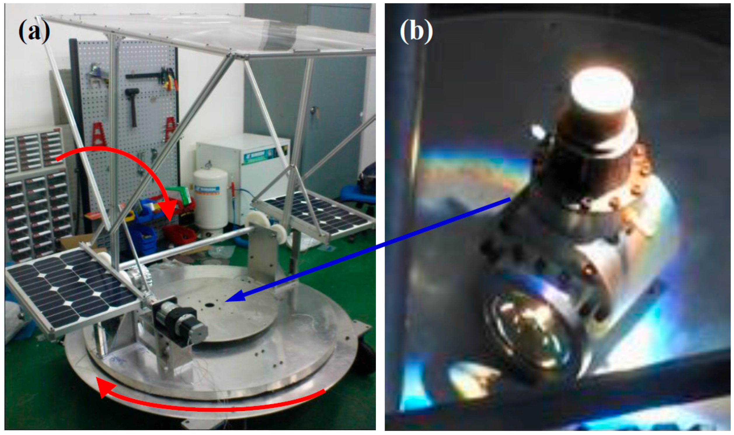
Figure 1. Biaxial-type tracking system: (a) System photo; (b) Sunlight focused on the heating head of the Stirling engine at the center of solar tracker (arrow pointing).
Applsci 06 00115 g001
Figure 2. The solar tracking system block diagram.
Applsci 06 00115 g002
Figure 3. Heating temperature diagram with different focus location of the heating head. (a) Sunlight cover the heating head (b) Sunlight focused on top of the heating head.
Applsci 06 00115 g003
Figure 4. The power of sunlight and the temperature of the copper heating head with thermal insulation cotton.
Applsci 06 00115 g004
Figure 5. (a) the temperature profile of the heating head and solar irradiation and (b) the energy gain energy consumption, solar cells temperature and atmosphere temperature at June 22, 2013.
Applsci 06 00115 g005