Article

Effect of Slot at Blade Root on Compressor Cascade Performance under Different Aerodynamic Parameters

1
National Key Laboratory of Science and Technology on Aero-Engine Aero-thermodynamics, School of Energy and Power Engineering, Beihang University, Beijing 100191, China
2
Collaborative Innovation Center of Advanced Aero-Engine, Beihang University, Beijing 100191, China
*
Author to whom correspondence should be addressed.
Appl. Sci. 2016, 6(12), 421; https://doi.org/10.3390/app6120421
Submission received: 9 November 2016 / Revised: 30 November 2016 / Accepted: 6 December 2016 / Published: 10 December 2016
(This article belongs to the Special Issue Gas Turbines Propulsion and Power)

Abstract

:
The effects of compressor aerodynamic parameters, such as pitch-chord ratio, aspect ratio, and fillet, on the cascade performance have been studied in this paper. Slot configuration at the root of the blade has been proved to be an efficient passive control method for the corner separation control in compressor cascade. The combined effects of the pitch-chord ratio, aspect ratio, and blade fillet with a slot configuration on the blade, have also been studied. Larger corner separation caused by the high pitch-chord ratio can be eliminated by the slot, which leads to fewer blades with almost the same or even better cascade performance. Various aspect ratios, together with the slot configuration, have been investigated and all of them have a positive effect on the cascade performance. For the blade with the blade fillet, the slot still has a positive effect on the control of the corner separation, while cascade performance with just a slot configuration is better than the slot configuration under the influence of the blade fillet.

1. Introduction

Corner separations always occur at the corner between the suction surface and the endwall, and are inherent flow features in compressors [1]. With the increased compressor loading or incidence angle, this 3D separation phenomenon can lead to the corner stall, thus contributing greatly to blockage and passage losses; therefore, it is considered as one of the most important factors limiting the loading capacity of a compressor. In the past few decades, many researchers have focused on understanding the mechanism of corner separation by experiment [2,3] or advanced numerical simulation methods (Delayed detached-eddy simulation (DDES) [4], hybrid LES/RANS [5], and Large eddy simulation (LES) [6]).
The onset of corner separations can be influenced by many parameters, such as compressor loading, inflow boundary layers, and real blade geometrical parameters including pitch-chord ratio, aspect ratio, and blade fillet. Many studies have been done to investigate the relationship between these parameters and the corner separation.
The pitch-chord ratio is the inverse of the solidity, which is an important parameter for the loading assessment. In the mid-20th century, Zweifel et al. [7] and Lieblein et al. [8] identified that the pitch-chord ratio (also solidity) is an important feature in compressor design. It strongly affects the flow turning angle, blade loading, and also the available range of incidence angles. In the past decades, lower pitch-chord ratio in compressors has become a routine design, as described by Obrecht et al. [9]. Keeping the chord length constant, a lower pitch-chord ratio means an increased number of blades, which leads to the increased compressor weight, higher fuel consumption, and more NOx emissions. The advanced aero engines now demand a higher pitch-chord ratio in the compressor in order to reduce the number of blades. A higher pitch-chord ratio creates larger separation zones, including corner separation in blade passages, which leads to more serious consequences, such as increased passage blockage, considerably higher pressure loss, and reduced compressor efficiency. Sans et al. [10] conducted a numerical study for the pitch-chord ratio effect on high Mach number flow regimes, which is more typical for modern compressors. This study concludes that at high positive incidence, the higher pitch-chord ratio cascade experiences more losses as compared to the lower pitch-chord ratio cascade. This can be explained by the higher loading endured for the higher pitch-chord ratio profile which also decreases the stability range of the cascade.
In the earlier axial compressor design, high aspect ratios were characterized to make the flow within the blade-row to be two-dimensional. The current trend towards the designing of low aspect-ratio airfoils in pursuit of higher stage loading can increase the three dimensionality of the flow within the entire blade-row. By lowering the aspect ratio an increase in stall pressure limit, operating range, and peak efficiency has been observed by Wennerstrom et al [11].
Some research has also been done to investigate the effects of blade fillet on three-dimensional separations. Goodhand et al. [12] have considered the effects of blade fillet geometry on the three-dimensional separation in compressor blade rows. The effects of the fillet radius were found to be of secondary importance. The effect of removing fillets was found to be detrimental by increasing the hub losses by 18%. Increasing the fillet radius to 10% of the chord was found to cause a small decrease in hub losses. The geometry of the leading edge fillet was found to have no effect on losses, even when it was extended out of the hub boundary layer. Curlett [13] has reported that by varying the fillet radius, the separation size, as well as the blade losses, were both influenced. Furthermore, the lowest losses have occurred with no fillet, while the highest losses have occurred with the largest fillet tested (rfillet/c = 15%). Brockett et al. [14] have considered the influence of fillet size in axial flow turbine stators. Small fillets, with a radius of about 5% of the chord, increased the efficiency by 1.4% compared with rfillet/c = 0%. It was anticipated that the increase in efficiency was due to the fillet, which has limited the corner separation; however, a further increase in fillet radius did not continue to increase in efficiency because of the additional associated profile drag. Stratford et al. [15] reported that in a compressor cascade, the addition of a fillet has increased the size of the separation region as well as the losses. Tweedt et al. [16] have investigated the influence of fillet size on stator performance in a two-stage axial flow compressor using double circular arc blades. The result did not show any prominent effects related to the fillet size. From the aforementioned literature study, it has not been determined concisely if the fillet geometry will have a positive or negative influence on corner separation for different blade profiles. Meyer et al. [17] have conducted three radius of blade fillet in a high speed compressor cascade. 3D flow structures of the secondary flow have been found shifting towards the symmetry plane which producing higher losses in the middle of the passage, but less near the endwall.
Due to the determinant effects of the corner separation, a significant amount of research has been done on various flow control techniques [18,19,20], but the passive control methods remain preferable because of their simplicity and cost effectiveness. For the research work of slot configurations, Razmi [21,22] has explored the potential of passive control via slotted blades in linear cascade configurations under stall conditions. 2D numerical study was conducted and the effects of location, width, and slope of slots were analyzed to identify the optimum configuration. The obtained results for the 2D case showed that the maximum of about a 28% reduction in loss coefficient has been observed and the flow turning was increased to approximately 5° with the slot. Wang et al. [23,24] have conducted research on a whole span slot on a National Advisory Committee for Aeronautics (NACA) blade and reported that, within the majority of the area of flux, the jet flow from the slot can reduce, as well as control, the separation of the tail of the suction surface, which can increase the efficiency and the stability of the blade. The slot configuration at the root of the blade was imposed by Mu et al. [25] to control the corner separation near the endwall.
In this research, the magnitude of changes in solidity, aspect ratio, and blade fillet radius, combined with effect of slot configuration at the blade root has been investigated for a highly-loaded compressor cascade. The objective was to find out how the design parameters (e.g., solidity and aspect ratio), the real geometrical aspect (blade fillet), and the slot configuration influence the corner separation, and also the overall performance of the cascade.

2. Numerical Methods
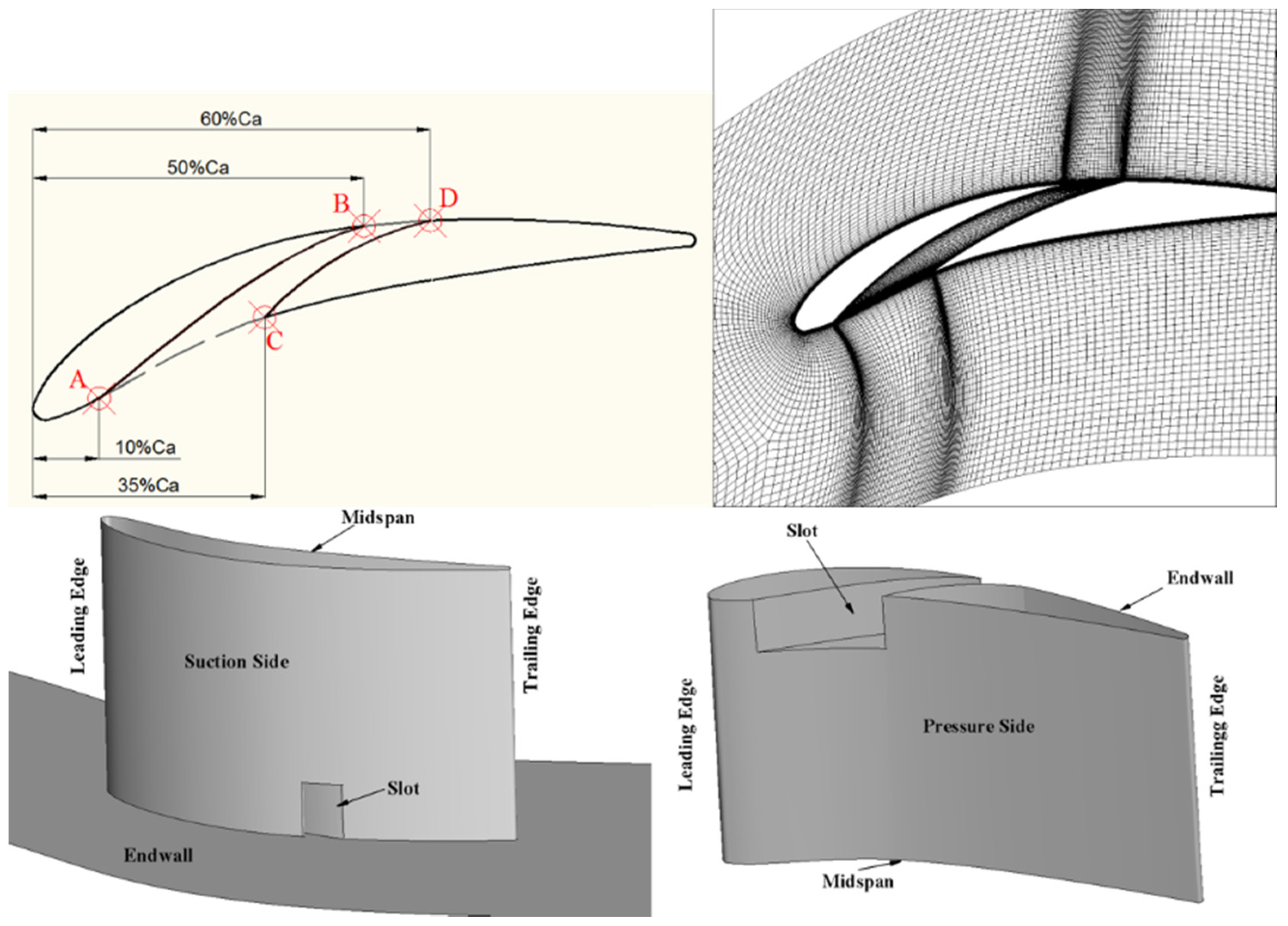
2.1. Cascade Model

In the current research, a linear compressor cascade, which was tested in the Whittle laboratory of the University of Cambridge [26,27], has been selected for the investigation of the corner separation. In our previous studies, turbulence model modification, flow mechanisms, and flow control for corner separation were conducted in the same cascade [28,29,30,31,32]. The test rig used in the experiment consisted of five modern PVD (prescribed velocity distribution) blades. Detailed aerodynamic and geometric parameters are listed in Table 1. The inlet Mach number is approximately 0.07 to yield a blade-chord-based Reynolds number Rec = 2.3 × 10⁵. The inlet free stream turbulence intensity is about 1.5% according to the experiment.
Figure 1 shows the geometry of the slot configuration used in this study. Line AB and CD are the boundaries of the slot, respectively. In order to introduce the mainstream flow from the blade pressure side into the slot without additional losses, line AB is set to be tangent to the pressure surface at point A. For the same purpose, line AB is tangent to the suction surface at point B to reduce the mixing losses between flow from the slot and the mainstream flow on the blade suction side. Hence line AB is defined as an S shape. Line CD is a circular arc which is tangent to the blade suction side at point D. The position of the slot is given in Figure 1. Point A is set at 10% axial chord from the leading edge and Point C is set at 35% of the axial chord from the leading edge to yield the slot inlet length lAC = 25%Ca. Point B is set at 50% of the axial chord from the leading edge and point D is set at 60% of the axial chord from the leading edge to yield the slot outlet length lBD = 10%Ca. The height of the slot is set at 10% of the whole blade span, which is 0.02 m. In order to guarantee y+ in the slot, a structure mesh is generated and the first mesh near the wall is set the same as the mesh around the blade, which is 10−5 m.

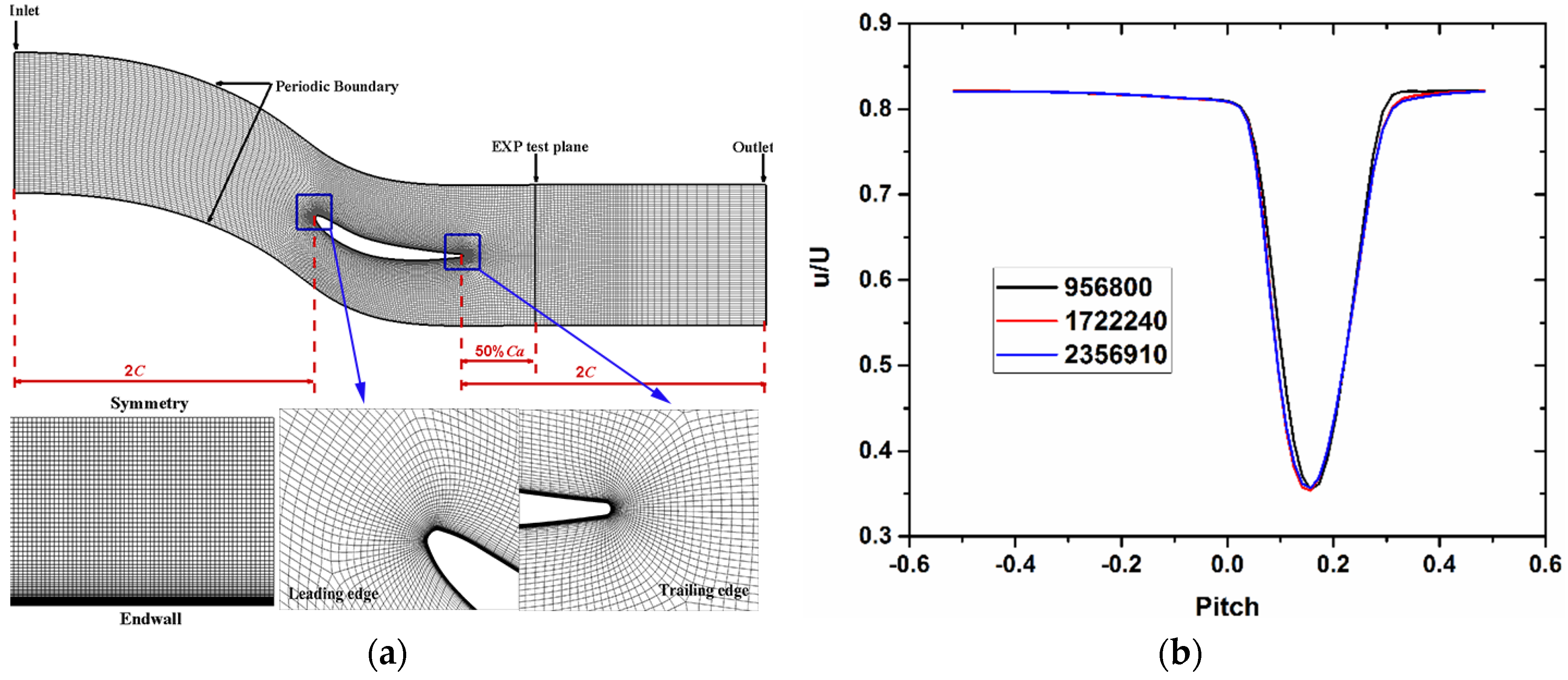
2.2. Grid and Numerical Technique

The numerical investigation presented was performed by using the commercial software Fluent (12.0, ANSYS Inc. Pittsburgh, PA, USA). The Reynold-stress model (RSM) is used for turbulence closure with enhanced wall treatment, since the previous work about corner separation has shown that the RSM model provided better correlation with the experimental data at a 0° incidence angle [32]. One blade passage is simulated and a periodic boundary condition is set on both sides of the flow passage. A structured O4H mesh topology is generated by using the commercial grid generation software Autogrid 5 in the investigation. Figure 2a shows the representative computational grid of the cascade, and the mesh is duplicated along the spanwise direction into 91 planes (half span) to obtain 3D mesh. The value of y+ adjacent to the wall is less than 1.0. Figure 2b shows the velocity distribution at 10% spanwise at the blade trailing edge for different number of grid at a 0° incidence angle. Results show little difference when the grid number reaches 1.7 millon, so case 2 with the total number of about 1.7 million grid points for the half-span of computational domain is selected for the simulation. The inlet plane is located at 2c upstream of the blade leading edge imposed with the same inlet velocity profile which has been configured to fit the experimental boundary layer. The outlet plane is located at 2c downstream of the blade trailing edge and the experimental downstream area traverses were carried out at about 50% of the axial chord from the trailing edge. Since only half of the blade span is simulated to reduce the computational cost, the midspan is set to be symmetric and the pitchwise boundaries are connected by the periodic condition. Both the blade and the endwall are set to be non-slip adiabatic walls.
The simple algorithm is used for the pressure-velocity coupling and the second-order upwind scheme is used for the spatial discretization of the equations. Enhanced wall treatment, which is a near-wall modeling method that combined a two-layer model with enhanced wall functions, was used to represent the turbulent flow in the near-wall region.

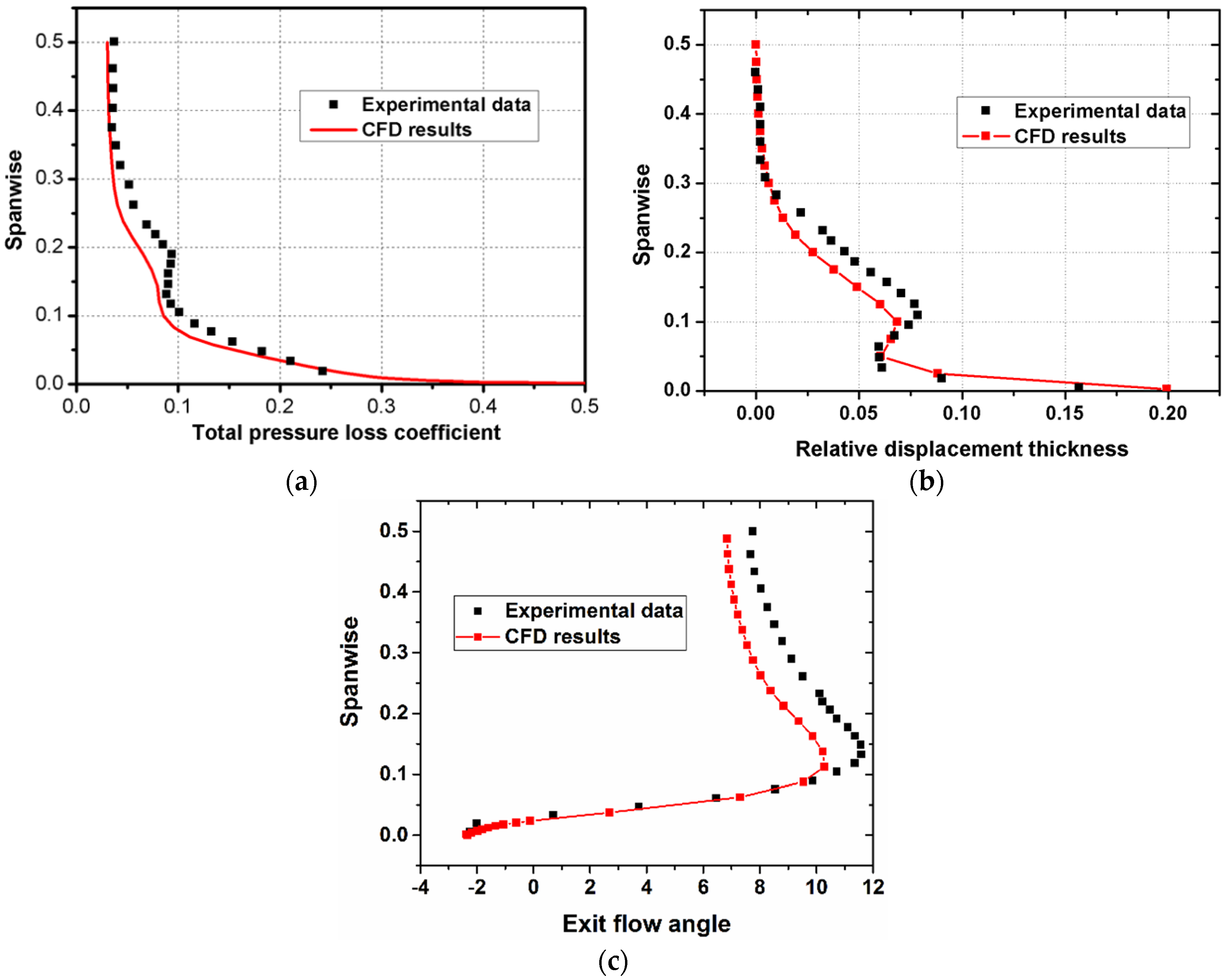
2.3. Validation of the Simulation Results

To further validate the CFD tool and the computational method, comparisons between the CFD result and the experimental results at a 0° incidence angle were performed. Figure 3 shows the computational results and the corresponding experimental data. Although some small deviations exist between the CFD and experimental results, reasonable agreement can be seen from Figure 3, which indicates that the size of 3D separation region in the blade passage is realistically predicted.
The total pressure loss coefficient is defined as:
Y p   =   P 02 P 01 P 01 P 1
where P 02 is the local total pressure, P 01 is the inlet total pressure, and P 1 is the inlet static pressure.
The relative displacement thickness can be expressed as:
δ r e l   =   { δ * ( r ) δ m i d s p a n * } / c
The displacement thickness is given as:
δ * ( r )   =   0 δ [ 1 ρ v ( r , s ) ρ f s V f s ] d s
Based on above analyses, it can be concluded that the numerical techniques and the commercial software FLUENT is reliable and can be used for the prediction of the 3D separation in this study.
The main mechanism for controlling of corner separation by the slot configuration is the flow induced from the pressure surface to the suction surface by the pressure difference can accelerate flow in the slot, which forms the jet flow from the slot, removing the low energy flow in the corner separation. Figure 4 shows the volume streamlines in the flow passage for the original cascade with and without the slot configuration. As shown in Figure 4, the adverse flow and blockage in the passage caused by the corner separation has been eliminated by the jet flow from the slot. The most important criteria for the slot is the outlet position of the slot which is correlated with the separation point of the corner separation. For the increasing of the incidence angle, separation point moves towards to the leading edge which also indicates the development of the corner separation. Based on the analysis of the outlet position of the slot, slot outlet position is set at 50% of the axial chord (which is the position of point B). In order to further accelerate the flow in the slot, a tapered shape is chosen for the slot. Thus, the inlet length and outlet length of the slot are set the 25% and 10% of the axial chord, respectively.

3. Results and Discussions

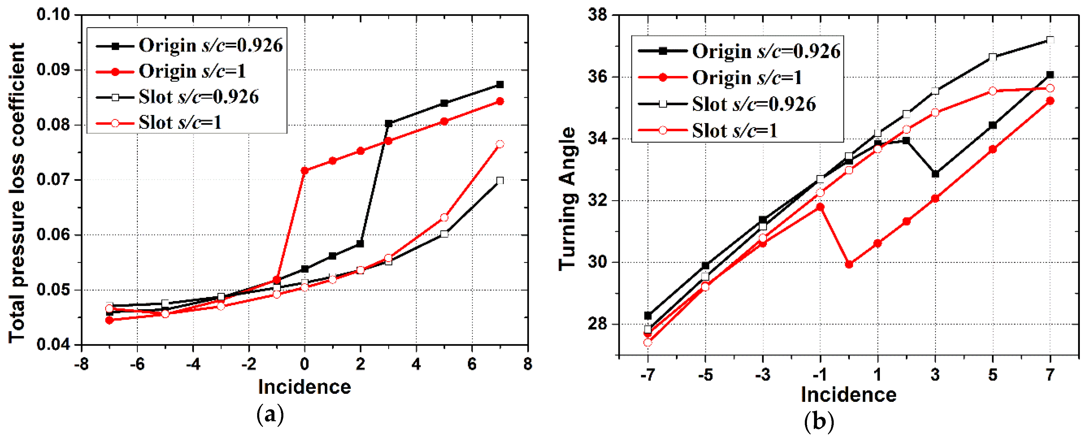
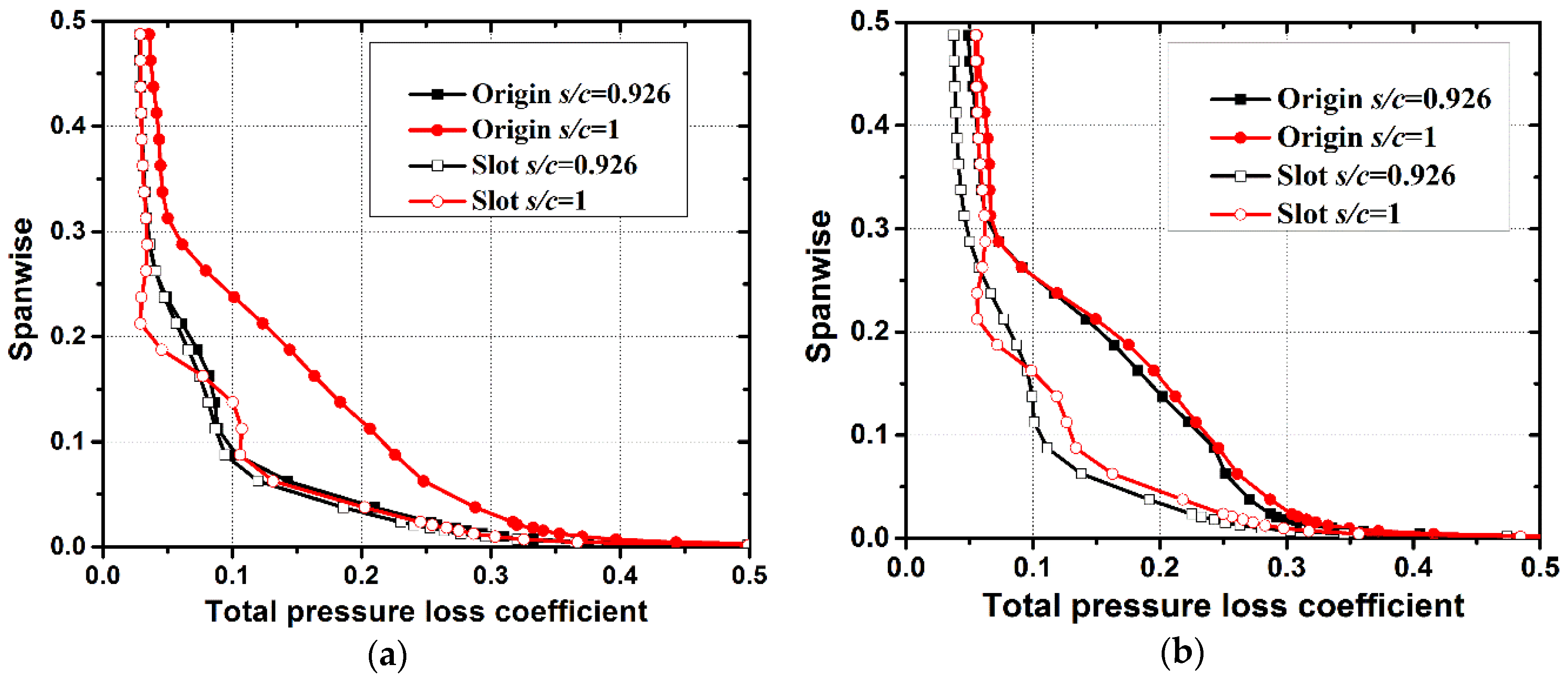
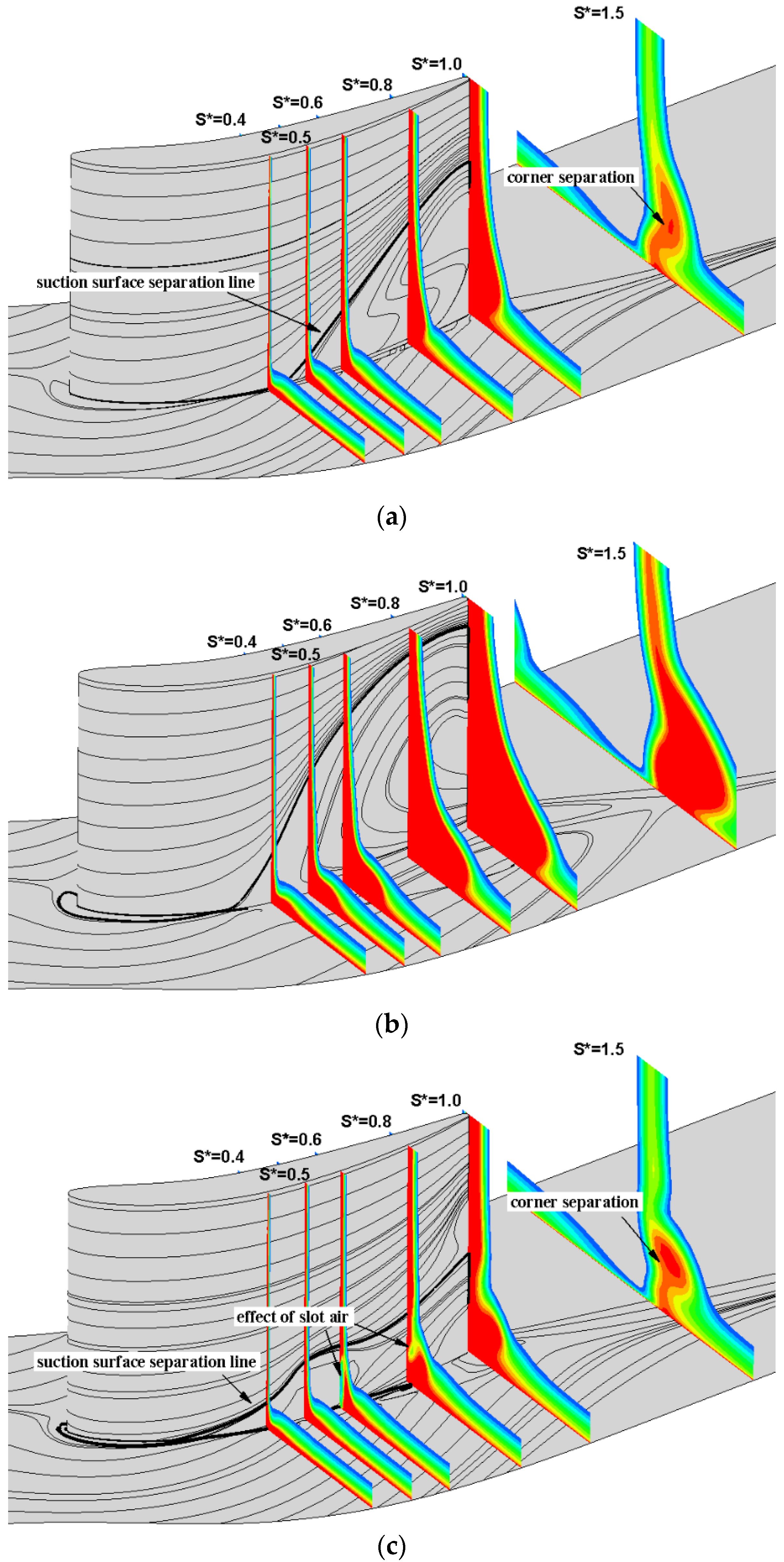
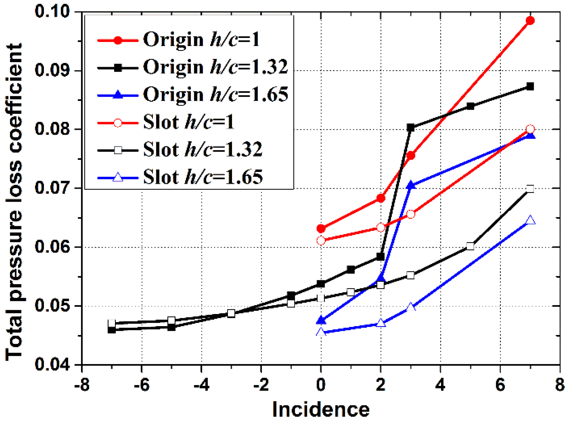
3.1. Effect of Pitch-Chord Ratio

Improvement of the pitch-chord ratio would cause an improvement of the loading and diffusion factor of the blade, which would also have a great impact on the corner separation in the passage. A large spread of the separated region with a significant extent of reverse flow was observed by Gbadebo [33] when the pitch-chord ratio increased from s/c = 0.6 to s/c = 1.25 (reduction in solidity). Based on the previous work of Mu et al. [25], the slot at the root of the blade has a significant effect to control the corner separation.
In order to understand the part played by the pitch-chord ratio with effects of the slot configuration at the root of blade, the datum chord length is maintained and the pitch-chord ratio is varied from the datum s/c = 0.926 to s/c = 1 with and without the effect of the slot configuration.
Figure 5 shows the influence of the pitch-chord ratio on the overall performance of the cascade from −7° to 7° incidence angles. The total pressure loss increases 33% in s/c from 0.926 to 1 at 0° incidence angle for the original cases. The slotted cascade significantly improved the overall performance, especially for the slotted cascade with s/c = 1. Although the original cascade stalls at a 0° incidence angle by the increase of the pitch-chord ratio, the performance of the slotted cascade is basically the same as the slotted cascade with s/c = 0.926 and the total pressure loss is significantly reduced compared with the original ones. Similar changes are also observed in Figure 4b for the turning angle.
Figure 6 shows the variation of the total pressure loss coefficient for the EXP test plane at i = 0° and 3° incidence angles. It is evident that the total pressure loss increases with increasing pitch-chord ratio for the original cases. This illustrates that more of the flow tends to be separated when the number of blades is decreased. The average total pressure loss reduces significantly in the corner region from the endwall to 30% spanwise by the slot configuration. The results correspond well to the above incidence characteristics. Furthermore, it can be predicted that the reduction of the flow blockages would be beneficial for improving the inlet working conditions of the downstream blade rows.
The surface flow pattern shown in Figure 7 indicates the influence of the pitch-chord ratio and slot configuration on the formation of the topological structure on the suction surface and the endwall. From Lei’s theory [34], three-dimensional separation develops from corner separation at s/c = 0.926 to hub-corner stall at s/c = 1 for the original cascade at a 0° incidence angle. The corresponding total pressure loss increases for the hub-corner stall case. While, for the slotted cascade at a larger pitch-chord ratio, the injection flow from the slot alters the nature of the hub-corner stall vortex. The most noticeable phenomenon is the remarkable reduction of the hub-corner stall in both its strength and size. The total pressure loss at the blade trailing edge is significantly weakened due to the changed endwall flowfield. Overall, the cascade performance has been significantly improved, which can be seen from Figure 4.

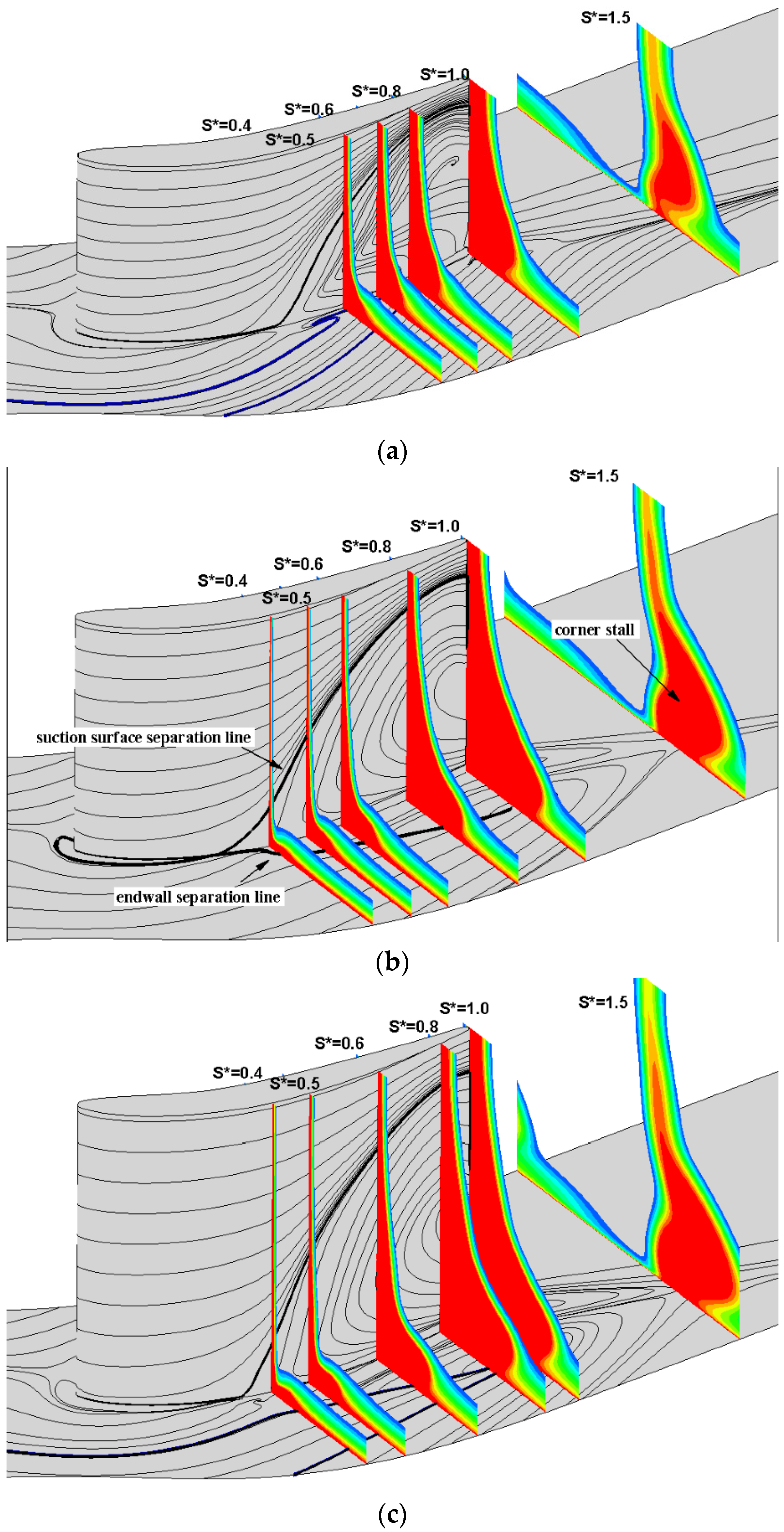
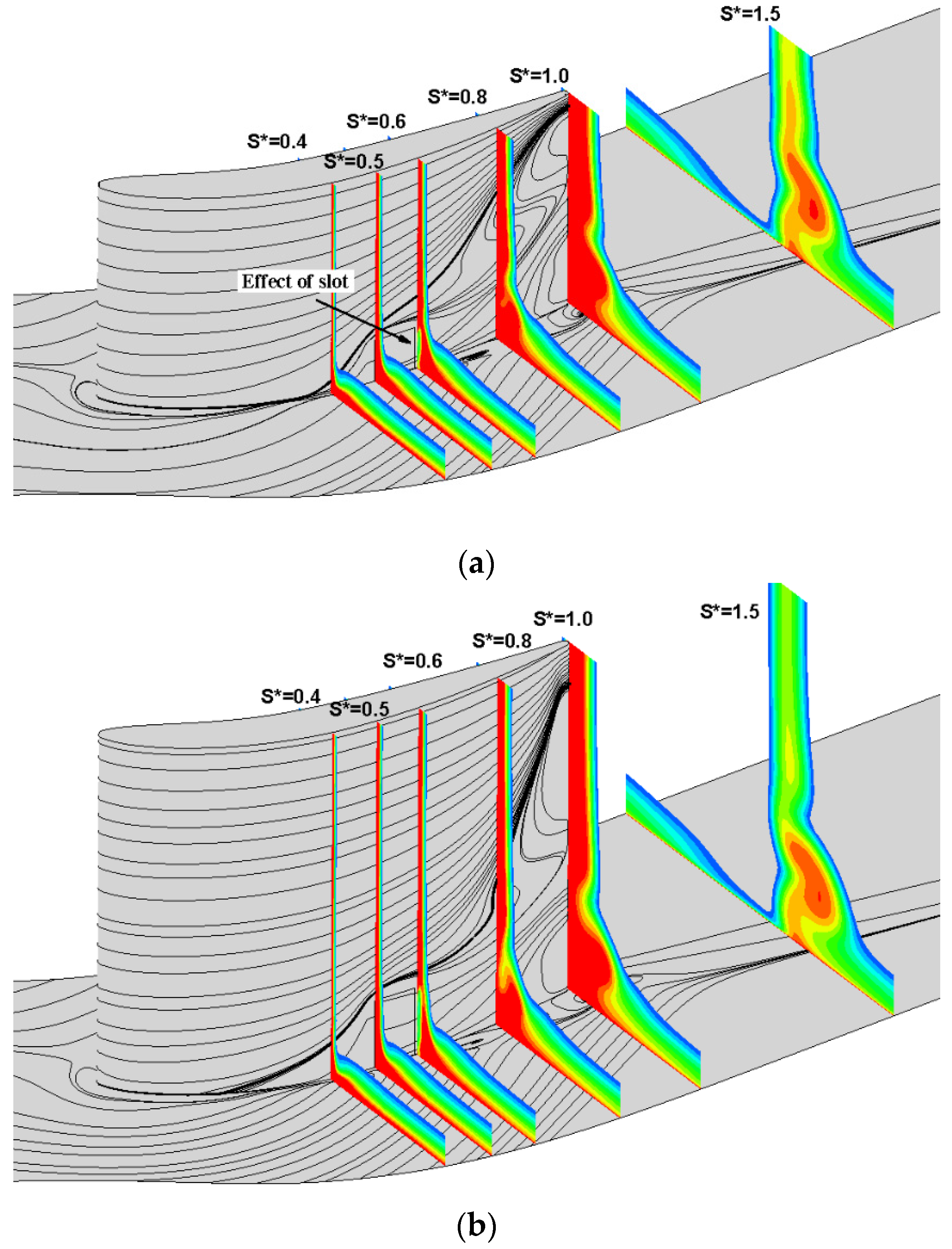
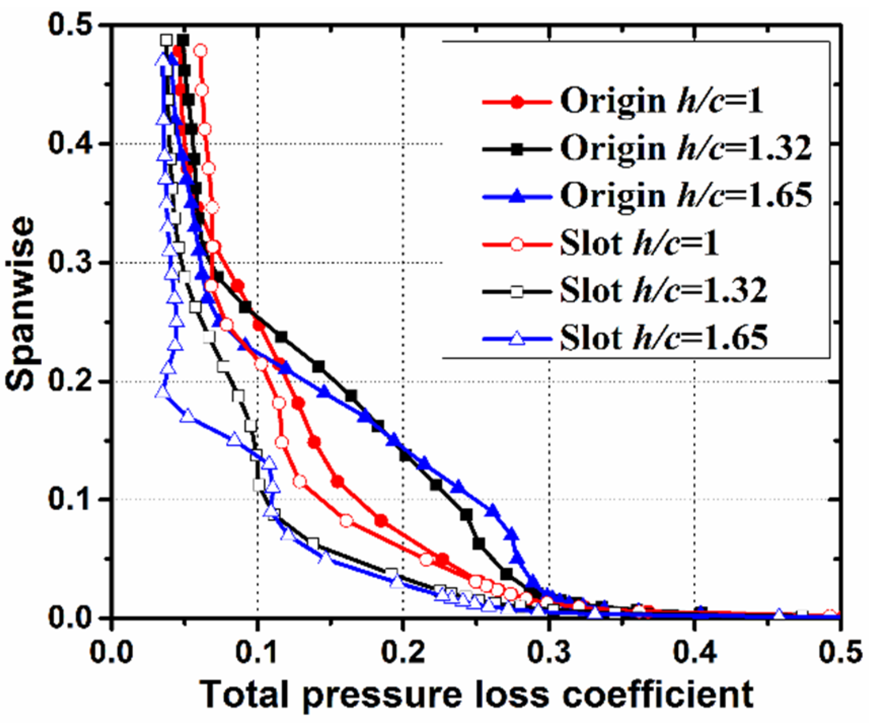
3.2. Effect of Aspect Ratio

A high aspect ratio is known to reduce secondary flow effects in the blade passage, but such blades are inclined to stall. The combined effect of aspect ratio and the slot configuration on the cascade performance is not known. In this study, the aspect ratio is set as an independent variable by changing the blade height, while keeping the chord constant. In order to understand the part played by the aspect ratio with effects on the slot configuration at the root of blade, the aspect ratio is varied from the datum h/c = 1.32 to h/c = 1 and h/c = 1.65, with and without the effect of the slot configuration. As for the original aspect ratio cascade, the height of the slot is set 10% of the whole span, so for the aspect ratio varied to h/c = 1 and h/c = 1.65, the height of the slot compared to the span height is kept as 10%, so the heights of the slot for these two cases are 0.01515 m and 0.025 m, respectively.
Figure 8 shows the influence of the aspect ratio on the overall performance of the cascade at positive incidence angles. For the incidence angle characteristics, just four representative incidence angles (i = 0°, 2°, 3°, 7°) were investigated. The original cascade tends to be easier to stall with the increasing aspect ratio. The total pressure loss increases gradually as the incidence angle increases for the h/c = 1 case. For h/c = 1.32 and h/c = 1.65 cases, total pressure loss increases rapidly at a 3° incidence angle, which corresponds to the generation of the corner stall. For the slotted cases total pressure loss decreases with the increase of the aspect ratio. This can be explained: as blade height increases, the proportion of the corner separation in the whole flow passage decreases.
Figure 9 shows the variation of the total pressure loss coefficient for the EXP test plane at the i = 3° incidence angle for three aspect ratios. The slot configuration for all the aspect ratio cascades worked well for the control of the corner separation. The total pressure loss decreased by 13%, 29.5%, and 31% for the aspect ratios of h/c = 1, h/c = 1.32, and h/c = 1.65, respectively. As the slot height increased along with the increase of the blade height, the slotted blade with h/c = 1.65 obtained the lowest loss at the blade trailing edge.
Figure 10 and Figure 11 shows the surface flow pattern and passage total pressure loss contour at the i = 3° incidence angle. With lower aspect ratio, the separation lines extend very close to the midspan in Figure 10a. While with the increase of the span height, flow near the endwall is uncoupled with the flow at the midspan, so a large separation near the endwall is generated and the three-dimensional separation is developed into the corner stall with a high aspect ratio. From the flow pattern of the slotted cases, jets from the slot have an impact on the high loss region on the blade suction surface side and prevented the flow drift towards the midspan and also caused an upward displacement of the limiting streamlines.

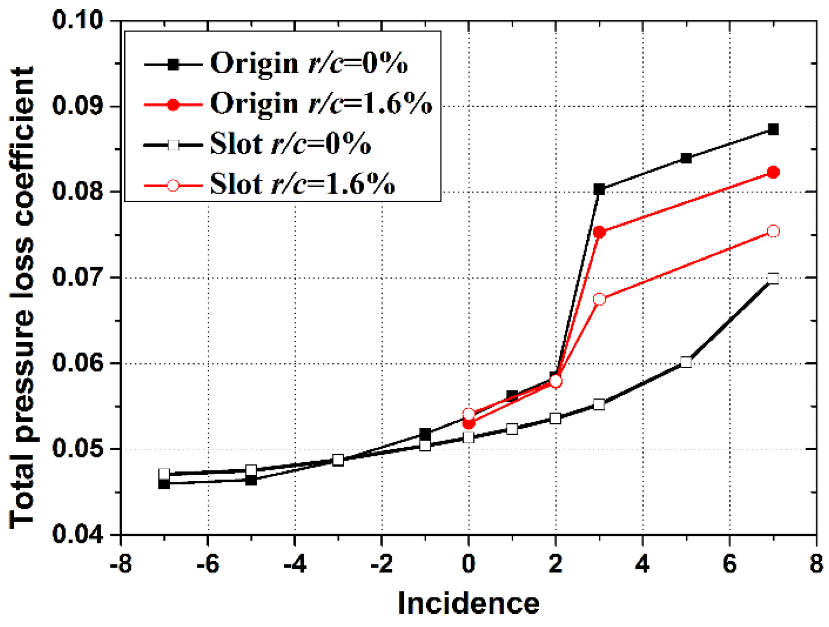
3.3. Effect of Blade Fillet

The small geometry deviations which are likely to occur in real machines, such as blade fillet, sometimes is recommended in conventional stators to improve structural integrity. The size of the fillet is usually minimized because increasing the fillet radius will decrease aerodynamic performance due to increased profile drag. However, the addition of a fillet between the blade and the hub will reduce the interaction between the endwall and blade boundary layers. Therefore, it has not been determined if the fillet geometry will have a positive or negative influence on corner separation [13]. In this study, fillet radii (rfillet/c = 0%, 1.6%) are tested on the PVD cascade to determine the effect of the fillet on this specific blade. Moreover, the slot configuration on blades with a fillet is also investigated to determine the combined effect of these two methods.
The effect of the fillet is shown in Figure 12. When a fillet is present, the total pressure loss coefficient decreases. For all of the cases, removing the fillet was found to increase loss, which is consistent with the results Goodhand [12] found in his study. For the cascade with blade fillet and slot configuration, the performance of the slotted cascade with rfillet/c = 1.6% is improved, compared with the original cascade with rfillet/c = 1.6%, while the total pressure loss coefficient is larger than the slot configuration without fillet. As the slot configuration is defined and analyzed from the original case, the slot geometry needs to be modified together with consideration of the blade fillet influence. In order to know the relationship between the blade fillet and the slot configuration, flow details in the passage are analyzed at the i = 3° incidence angle below.
Figure 13 shows the limiting streamlines and the total pressure loss coefficient in the passage for different fillet radii at the i = 3° incidence angle. As the fillet would affect the interaction of the suction surface boundary layer with the overturned endwall flow, from the red streamline in Figure 13b, flow near the endwall has a tendency to move along the suction surface and shift to the midspan. The total pressure loss decreases slightly near the endwall, while increasing near the midspan, which is consistent with the results of Meyer et al. [17]. From Figure 13c, the slot configuration still has a positive effect on the corner separation and the large reverse region on the endwall has been eliminated. While 2D separation is generated about 20%h to the midspan and the profile loss on the suction surface has been increased.
For the results on PVD cascade, comparing with the cascade without fillet, the slot configuration still has a positive effect on controlling the corner separation, while the effect of the slot configuration under the influence of the blade fillet is worse than the slot configuration without fillet. The reasons are as follows: one reason is that as the fillet can influence the interaction of the blade suction flow with the endwall overturned flow, the corner separation flow structure might be changed compared with the original case. Slot geometry needs to be modified or improved for the new flow pattern. The other reason is the combination effect of the slot configuration and the blade fillet leads to the increase of the total pressure loss coefficient near the midspan.

4. Conclusions

Compressor aerodynamic parameters and the blade fillet have shown strong influences on the corner separation and also on the cascade performance for a certain range of incidence angles. Based on the previous work, the slot configuration on the reference PVD cascade can decrease the total pressure loss and blockage in the passage and then improve the cascade performance. The slot configuration, combined with the aerodynamic parameters and fillet which may influence the corner separation, have been studied to determine how cascade performance would be affected by these parameters. The following are a few findings of this research work:
(a)
High pitch-chord ratio blades are inclined to stall with the increase of the loading for each blade. With the slot configuration, the overall performance of the high pitch-chord ratio cascade is almost the same with reference to low pitch-chord ratio by reducing the corner separation in the cascade. Therefore, a slot can be used to decrease the number of blades to improve the thrust-weight ratio and to avoid large separation caused by the high loading of the blade.
(b)
High aspect ratio blades are also inclined to stall. For the low aspect ratio, flow becomes three-dimensional almost over the entire blade span and the influence of the corner separation plays a more important role in the flow passage. For all of the aspect ratios studied, slot configuration still has a positive effect on the corner separation and the overall performance of the cascade has been improved.
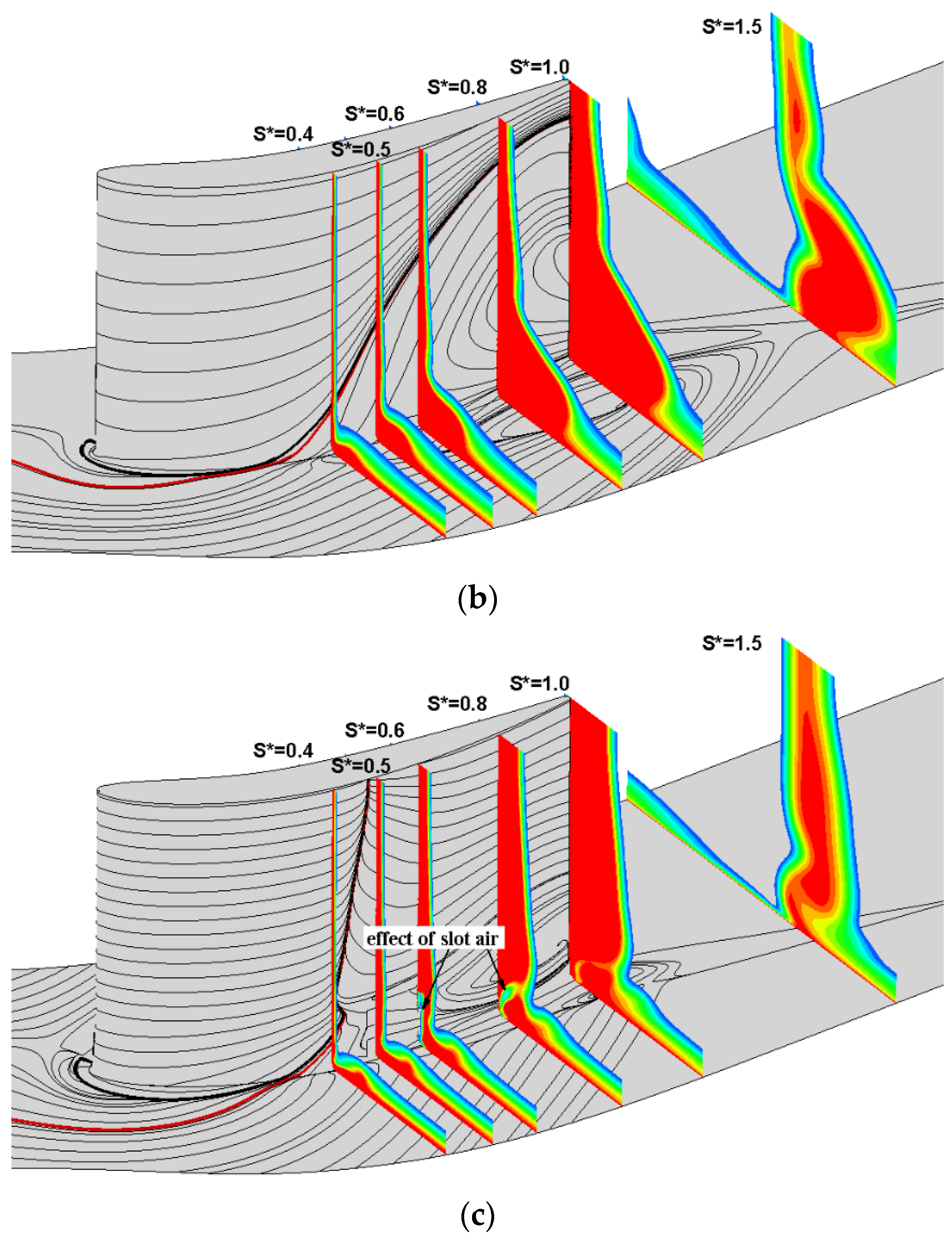
(c)
For the PVD cascade investigated in this study, flow near the endwall has shown some improvement, while a radical shift of the results is also evident. For the blade with fillet more studies are required to be carried out to understand the relationship between blade fillet, slot configuration, and the corner separation.

Acknowledgments

This work is supported by the National Natural Science Foundation of China (No. 51676007, No. 51376001, No. 51420105008, No. 51136003), and the National Basic Research Program of China (2014CB046405). Yangwei Liu was supported by the China Scholarship Council (CSC). Theauthors would like to thank Whittle Laboratory and Rolls-Royce Plc for providing their experimental results.

Author Contributions

This paper is a result of the collaboration of all authors. All authors have previous experience on flow control and numerical simulation that have been shared in order to reach the results discussed in the paper. Yangwei Liu and Jinjing Sun meditated this paper. Yumeng Tang has done the validation of the turbulence model and grid independence. Lipeng Lu has supervised the research work. All authors discussed the results and implications and commented on the manuscript at all stages.

Conflicts of Interest

The authors declare no conflict of interest.

References

  1. Wisler, D.C. Loss reduction in axial-flow compressors through low-speed model testing. J. Eng. Gas Turbines Power 1985, 107, 354–363. [Google Scholar] [CrossRef]
  2. Zambonini, G.; Ottavy, X. Unsteady pressure investigations of corner separated flow in a linear compressor cascade. In Proceedings of the ASME Turbo Expo 2015: Turbine Technical Conference and Exposition, Montreal, QC, Canada, 15–19 June 2015.
  3. Zambonini, G.; Ottavy, X.; Kriegseis, J. Corner Separation Dynamics in a Linear Compressor Cascade. In Proceedings of the ASME Turbo Expo 2016: Turbomachinery Technical Conference and Exposition, Seoul, Korea, 13–17 June 2016.
  4. Liu, Y.; Yan, H.; Lu, L.; Li, Q. Investigation of Vortical Structures and Turbulence Characteristics in Corner Separation in a Linear Compressor Cascade Using DDES. ASME J. Fluids Eng. 2016. [Google Scholar] [CrossRef]
  5. Wang, Z.; Yuan, X. Unsteady mechanisms of compressor corner separation over a range of incidences based on hybrid LES/RANS. In Proceedings of the ASME Turbo Expo 2013: Turbine Technical Conference and Exposition, San Antonio, TX, USA, 3–7 June 2013.
  6. Gao, F.; Ma, W.; Zambonini, G.; Boudet, J.; Ottavy, X.; Lu, L.; Shao, L. Large-eddy simulation of 3-D corner separation in a linear compressor cascade. Phys. Fluids 2015, 27, 085105. [Google Scholar] [CrossRef]
  7. Zweifel, O. The spacing of turbo-machine blading, especially with large angular deflection. Brown Boveri Rev. 1945, 32, 436–444. [Google Scholar]
  8. Lieblein, S.; Schwenk, F.C.; Broderick, R.L. Diffusion Factor for Estimating Losses and Limiting Blade Loadings in Axial-Flow-Compressor Blade Elements; No. NACA-RM-E53D01; National Advisory Committee for Aeronautics, Lewis Flight Propulsion Lab: Cleveland, OH, USA, 1953.
  9. Obrecht, T. HP compressor preliminary design. In Advances in Axial Compressor Aerodynamics; Von Karman Institute for Fluid Dynamics Lecture Series VKI-LS 3; Von Karman Institute for Fluid Dynamics: Sint-Genesius-Rode, Belgium, 2013. [Google Scholar]
  10. Sans, J.; Resmini, M.; Brouckaert, J.F.; Hiernaux, S. Numerical investigation of the solidity effect on linear compressor cascades. In Proceedings of the ASME Turbo Expo 2014: Turbine Technical Conference and Exposition, Dusseldorf, Germany, 16–20 June 2014.
  11. Wennerstrom, A.J. Low aspect ratio axial flow compressors: Why and what it means. J. Turbomach. 1989, 111, 357–365. [Google Scholar] [CrossRef]
  12. Goodhand, M.N.; Miller, R.J. The impact of real geometries on three-dimensional separations in compressors. J. Turbomach. 2012, 134, 021007. [Google Scholar] [CrossRef]
  13. Curlett, B.P. The Aerodynamic Effect of Fillet Radius in a Low Speed Compressor Cascade; NASA TM-105347; NASA Lewis Research Center: Cleveland, OH, USA, November 1991.
  14. Brockett, W.; Andrew, K. Small Axial Turbine Stator Technology Program; NASA CR-165602; NASA: Stratford, CT, USA, April 1982.
  15. Stratford, B.S. The prevention of separation and flow reversal in the corners of compressor blade cascades. Aeronaut. J. 1973, 77, 249–256. [Google Scholar]
  16. Tweedt, D.L.; Okiishi, T.H. Stator Blade Row Geometry Modification Influence on Two-Stage, Axial-Flow Compressor Aerodynamic Performance; No. ISU-ERI-AMES-84179; Iowa State Univ Ames Engineering Research Inst.: Ames, IA, USA, 1983. [Google Scholar]
  17. Meyer, R.; Schulz, S.; Liesner, K.; Passrucker, H.; Wunderer, R. A parameter study on the influence of fillets on the compressor cascade performance. J. Theor. Appl. Mech. 2012, 50, 131–145. [Google Scholar]
  18. Siemann, J.; Krenz, I.; Seume, J.R. Experimental Investigation of Aspiration in a Multi-Stage High-Speed Axial-Compressor. In Proceeding of the ASME Turbo Expo 2016: Turbomachinery Technical Conference and Exposition, Seoul, Korea, 13–17 June 2016.
  19. Liesner, K.; Meyer, R.; Lemke, M.; Gmelin, C.; Thiele, F. On the efficiency of secondary flow suction in a compressor cascade. In Proceedings of the ASME Turbo Expo 2010: Power for Land, Sea, and Air, Glasgow, UK, 14–18 June 2010.
  20. Liesner, K.; Meyer, R.; Schulz, S. Non-symmetrical boundary layer suction in a compressor cascade. J. Theor. Appl. Mech. 2012, 50, 455–472. [Google Scholar]
  21. Ramzi, M.; AbdErrahmane, G. Passive Control via Slotted Blading in a Compressor Cascade at Stall Condition. J. Appl. Fluid Mech. 2013, 6, 571–580. [Google Scholar]
  22. Ramzi, M.; Gérard, B.; Abderrahmane, G. Numerical study of passive control with slotted blading in highly loaded compressor cascade at low Mach number. Int. J. Fluid Mach. Syst. 2011, 4, 97–103. [Google Scholar] [CrossRef]
  23. Zhou, M.; Wang, R.; Bai, Y.; Zeng, L. Numerical research on effect of stator blade slot treatment on single stage compressor characteristic. Acta Aerodyn. Sin. 2008, 26, 0258. (In Chinese) [Google Scholar]
  24. Zhou, M.; Wang, R.; Cao, Z.; Zhang, X. Research on effect of slot inlet angle and turning angle on the flow field characteristic of cascade. J. Aerospace Power 2008, 1, 021. (In Chinese) [Google Scholar]
  25. Mu, X.; Lu, L. Corner separation control by bleed slot at the root of blade. Gas Turbine Exp. Res. 2007, 20, 28–33. (In Chinese) [Google Scholar]
  26. Gbadebo, S.A.; Cumpsty, N.A.; Hynes, T.P. Three-dimensional separations in axial compressors. J. Turbomach. 2005, 127, 331–339. [Google Scholar] [CrossRef]
  27. Gbadebo, S.A.; Cumpsty, N.A.; Hynes, T.P. Control of three-dimensional separations in axial compressors by tailored boundary layer suction. J. Turbomach. 2008, 130, 011004. [Google Scholar] [CrossRef]
  28. Liu, Y.; Yan, H.; Liu, Y.; Lu, L.; Li, Q. Numerical Study of Corner Separation in a Linear Compressor Cascade Using Various Turbulence Models. Chin. J. Aeronaut. 2016, 29, 639–652. [Google Scholar] [CrossRef]
  29. Liu, Y.; Yan, H.; Fang, L.; Lu, L.; Li, Q.; Shao, L. Modified k-ω model Using Kinematic Vorticity for Corner Separation in Compressor Cascade. Sci. China Technol. Sci. 2016, 59, 795–806. [Google Scholar] [CrossRef]
  30. Liu, Y.; Lu, L.; Fang, L.; Gao, F. Modification of Spalart–Allmaras Model with Consideration of Turbulence Energy Backscatter Using Velocity Helicity. Phys. Lett. A 2011, 375, 2377–2381. [Google Scholar] [CrossRef]
  31. Liu, Y.; Yan, H.; Lu, L. Numerical Study of the Effect of Secondary Vortex on Three-Dimensional Corner Separation in a Compressor Cascade. Int. J. Turbo Jet-Engines 2016, 33, 9–18. [Google Scholar] [CrossRef]
  32. Liu, Y.; Sun, J.; Lu, L. Corner separation control by boundary layer suction applied to a highly loaded axial compressor cascade. Energies 2014, 7, 7994–8007. [Google Scholar] [CrossRef]
  33. Gbadebo, S.A. Three-Dimensional Separational in Compressors. Ph.D. Thesis, University of Cambridge, London, UK, 2003. [Google Scholar]
  34. Lei, V.M.; Spakovszky, Z.S.; Greitzer, E.M. A criterion for axial compressor hub-corner stall. J. Turbomach. 2008, 130, 031006. [Google Scholar] [CrossRef]
Figure 1. Geometry of the slot configuration.
Applsci 06 00421 g001
Figure 2. Grid independence test: (a) view of the computation domain and RANS mesh; and (b) velocity distribution at 10% of the span at the trailing edge.
Applsci 06 00421 g002
Figure 3. Spanwise distribution of pitch-averaged flow parameters at the EXP test plane: (a) pitch-averaged total pressure loss coefficient; (b) relative displacement thickness; and (c) exit flow angle.
Applsci 06 00421 g003
Figure 4. Volume streamlines in the flow passage: (a) original cascade; and (b) slotted cascade.
Applsci 06 00421 g004
Figure 5. Influence of pitch-chord ratio for different incidence angles on: (a) total pressure loss coefficient; and (b) flow turning angle.
Applsci 06 00421 g005
Figure 6. Influence of pitch-chord ratio on the spanwise profile of the total pressure loss coefficient: (a) i = 0°; and (b) i = 3°.
Applsci 06 00421 g006
Figure 7. Influence of pitch-chord ratio on limiting streamlines and the passage total pressure loss coefficient at i = 0° incidence angle: (a) origin, s/c = 0.926; (b) origin, s/c = 1; and (c) slot, s/c = 1.
Applsci 06 00421 g007
Figure 8. Influence of the aspect ratio for different incidence angles on the total pressure loss coefficient with and without the slot configuration.
Applsci 06 00421 g008
Figure 9. Influence of aspect ratio on the spanwise profile of total pressure loss coefficient at the i = 3° incidence angle.
Applsci 06 00421 g009
Figure 10. Influence of aspect ratio on limiting streamlines and the passage total pressure loss coefficient at the i = 3° incidence angle: (a) origin, h/c = 1; (b) origin, h/c = 1.32; and (c) origin, h/c = 1.65.
Applsci 06 00421 g010
Figure 11. Influence of aspect ratio combined with the slot on limiting streamlines and the passage total pressure loss coefficient at the i = 3° incidence angle: (a) slot, h/c = 1; and (b) slot, h/c = 1.65.
Applsci 06 00421 g011
Figure 12. Influence of fillet radius for different incidence angles on the total pressure loss coefficient without the slot configuration.
Applsci 06 00421 g012
Figure 13. Influence of blade fillet on limiting streamlines and the passage total pressure loss coefficient at the i = 3° incidence angle: (a) origin, rfillet/c = 0%; (b) origin, rfillet/c = 1.6%; and (c) slot, rfillet/c = 1.6%.
Applsci 06 00421 g013aApplsci 06 00421 g013b
Table 1. Aerodynamic and geometric parameters of the cascade.
NameSymbolMagnitude
Chordc151.5 mm
Pitch to Chords/c0.926
Aspect ratioh/c1.32
Camber angleψ14.7°
Stagger angleγ42°
Reynolds numberRec2.3 × 105

