1. Introduction
A traditional motor drive system is combined with an electromagnetic component (e.g., DC motor, induction motor, permanent magnet synchronous motor, and switched reluctance motor) and mechanical component (e.g., gear box, transmission). Some drawbacks are added into the system by using mechanical components, such as friction loss, maintenance cost and noise. Therefore, the direct drive motor system is proposed to avoid problems. In a direct motor drive system, the motor is coupled with load directly, and the direct drive motors are usually needed to own the features of low working speed and high output torque in most direct-drive applications (e.g., electrical vehicle, wave energy conversion, ship propulsion, railway traction, and wind power generation).
A series of motor technologies has been investigated for direct-drive applications, such as the multi-pole permanent magnet synchronous motor (PMSM) [
1], the brushless DC motor (BLDC) [
2], the permanent magnet vernier motor (PMVM) [
3,
4,
5] and the transverse flux motor (TFM) [
6,
7,
8,
9]. Among those motor technologies, the transverse flux motor has a unique transverse main flux path that is perpendicular to the rotate direction. In contrast to the radial flux technologies, the feature of the transverse flux path makes the electrical load and the magnetic load be decoupled from each other, which improves the torque density and the feasibility for multi-pole design. Nevertheless, the structure of TFM is usually complex as the 3D flux path, and the use of a silicon steel sheet is laminated. The soft magnetic composite (SMC) is a reasonable material for TFM [
10]; however, the mechanical strength and magnetic characteristic of SMC is lower than a silicon steel sheet.
Various transverse flux motor structures have been proposed and researched by the scholars around the world [
11,
12,
13,
14]. They can be classified into synchronous type and reluctance type [
15]: (1) if the permanent magnets are fixed on the rotor side (including mounted on the rotor core surface or buried into the rotor core), the motor can be classified as a transverse flux permanent magnet synchronous motor (TFPM) [
16,
17]; (2) if there is no permanent magnet on the rotor side, the motor can be classified as a transverse flux reluctance motor (TFRM) [
18]. The TFPM can obtain larger torque density than the TFRM; meanwhile, the manufacturing cost of TFRM is lower and reliability of TFRM is higher. Thus, the cost and the characteristics of motors should both be considered.
In this paper, a transverse-flux motor using a combined-type stator core (CS-TFM) is proposed. The CS-TFM is a kind of external rotor motor. The rotor is comprised of a rotor teeth core and non-magnetic sleeve. The stator is comprised of a core, permanent magnet and armature winding. Both the rotor core and the stator core can be fabricated by a silicon steel sheet, which can improve the mechanical strength and simplify the processing technique. Both permanent magnet and armature winding are fixed on the stator side, and the rotor structure is simple and reliable. The torque density of CS-TFM is improved more than TFRM by using a permanent magnet, and the cost is lower than TFPM as the PM volume of CS-TFM is smaller.
In
Section 2, the detailed motor structure and working principles are introduced. In
Section 3, the theoretical expressions of electromagnetic torque and cogging torque are deduced. In
Section 4, the basic characteristics such as permanent magnet flux linkage, no-load back electromotive force (no-load BMF), cogging torque, and load torque are analyzed by 3D FEM in detail. In
Section 5, the influence of structure parameters on the torque density is analyzed. In
Section 6, the torque densities of different direct-drive motor technologies are calculated and compared, and a summary is included in
Section 7.
2. Structure and Working Principles of TFM
2.1. Basic Structure
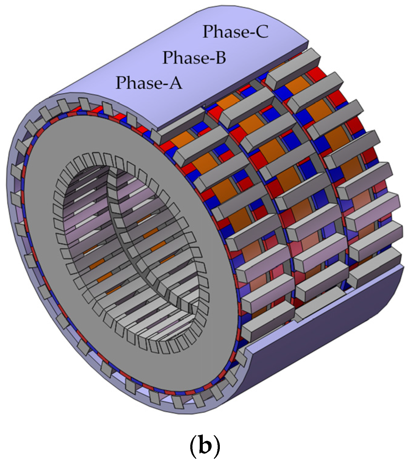
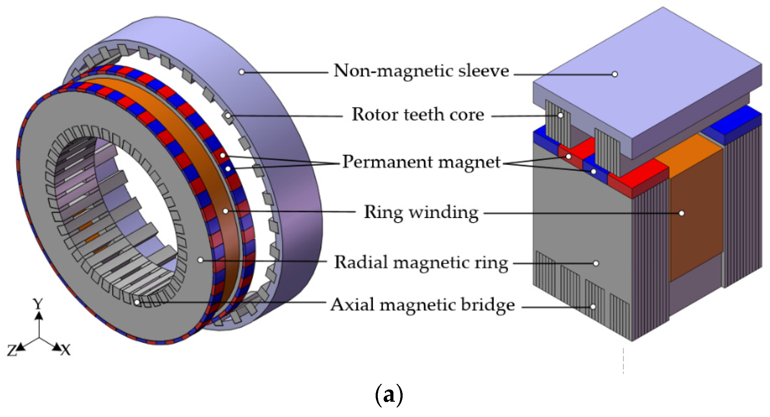
The basic single-phase unit structure is shown in
Figure 1a. The stator core is comprised of two radial magnetic rings and several axial magnetic bridges. Both the radial flux ring and the axial flux bridge can be manufactured by silicon-steel sheets, and the direction of lamination is shown in
Figure 1a; the armature winding is ring-shaped, and it is fixed in the coil window of stator core; the PMs are radial magnetized and fixed on the outer surface of the radial flux ring, each two adjacent PMs on the same radial flux ring have opposite magnetization direction, and each two axially corresponding PMs on two different radial flux rings also have opposite magnetization direction; the rotor is comprised of rotor teeth cores and a non-magnetic sleeve. Three-phase motor structure can be assembled by arranging three single-phase units along the axial direction with 120° electrical angle difference between each other, as shown in
Figure 1b.
2.2. Working Principle
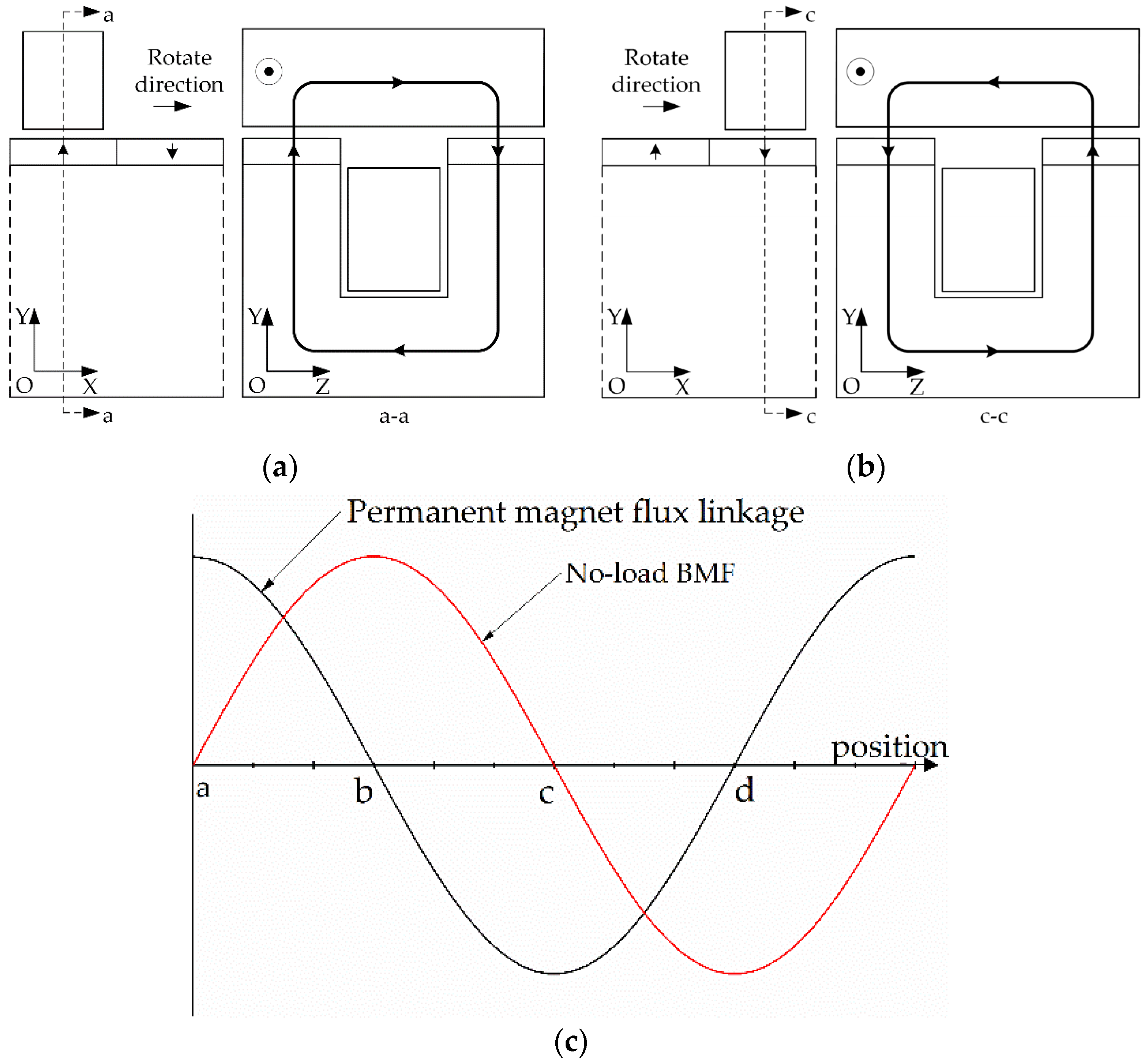
The permanent magnet flux path of CS-TFM at two special rotor positions are shown in
Figure 2a,b. The PM flux linkage reaches the positive maximum value at position a, and then reaches the negative maximum value at position c. When the leakage flux is neglected, the main flux from the PM goes radially through the air gap into a rotor teeth core, passing then axially along the rotor teeth core, again radially inward passing the air gap and the axially corresponding PM, passing then radially along the radial magnetic ring and axially along the axial magnetic bridge, again radially along the other radial magnetic ring, and finally returning to the PM, completing a flux loop. It can be seen that the flux path of proposed CS-TFM is transversal to the rotate vector of the rotor, and CS-TFM is a kind of transverse flux technology.
As the variation of the magnetic circuit reluctance is due to the “teeth-slot” structure of rotor when the rotor rotates, the PM flux linkage in the armature winding is a variable about rotor teeth core position (e.g., the flux linkage direction reverses from position a to position c), and the variable flux linkage can induce a back electromotive force (BMF) in the armature winding, as shown in
Figure 2c. When alternating sinusoidal current is applied in the winding, the BMF interacts with the current to generate electromagnetic torque.
2.3. Structure Advantages
Based on the foregoing introduction of CS-TFM, the following advantages can be listed:
Using silicon-steel sheet. The special combined-type stator core of proposed CS-TFM makes it possible to use silicon-steel sheets for 3D flux path. Thus, the magnetic performance and mechanical strength of CS-TFM can be improved more than the TFM using soft magnetic materials (SMC).
High reliability. Both permanent magnet and armature winding are fixed on the stator side, and the rotor only be comprised of tooth cores and a non-magnetic sleeve. This structure feature improves the reliability of motor.
3. Theoretical Analysis of Torque Characteristic of TFM
In order to simplify the magnetic field analysis of motor, some acceptable assumptions are adopted here: (1) the permeance of core is infinity, and the magnetic potential difference in core is ignored; (2) the permeance of permanent magnet is equal to that of air; (3) the eddy and hysteresis effects are ignored; and (4) the saturation effect of the core is ignored.
3.1. Electromagnetic Torque
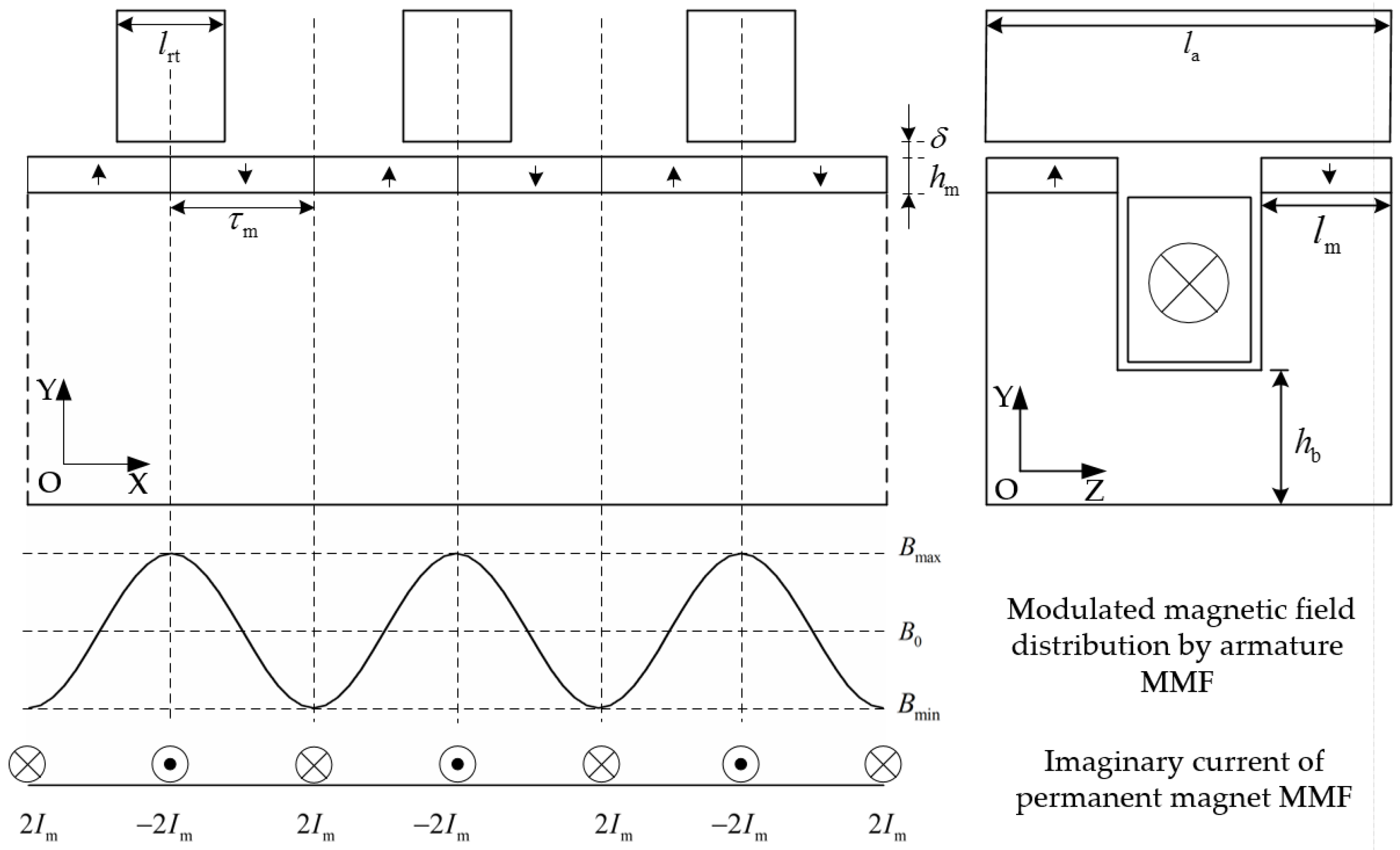
The torque of CS-TFM can be seen as the interaction between the rotor core and the air-gap magnetic field, which is the sum of the permanent magnet field and the armature current magnetic field. It can also be explained in the magnetic field modulation method as shown in
Figure 3: the distribution of magnetic field excited by armature current magnetomotive force (MMF) is modulated by the rotor teeth, and the MMF of permanent magnet can be replaced by the magnetizing imaginary current
Im at the boundaries of the permanent magnet. Then, the torque of TFM is generated by the interaction of a modulated armature magnetic field and imaginary current. Thus, the electromagnetic torque can be calculated conveniently by the classical electromagnetic equation of “BIL”.
From
Figure 3, the air-gap flux density of armature MMF is a periodic function about position, the period is two times that of permanent magnet pole-pitch τ
m When the center-line of rotor teeth is aligned to the center-line of permanent magnet (as the position shown in
Figure 2a), the position is signed as “origin”, and the expression of air-gap flux density can be written as Fourier series:
where
B0 is the constant component,
Bn is the harmonic component,
Bteeth is the flux density in the teeth area,
Bslot is the flux density in the slot area, τ
m is the permanent magnet pole-pitch,
lrt is the circumferential rotor teeth length, and
x is the distance between position and origin.
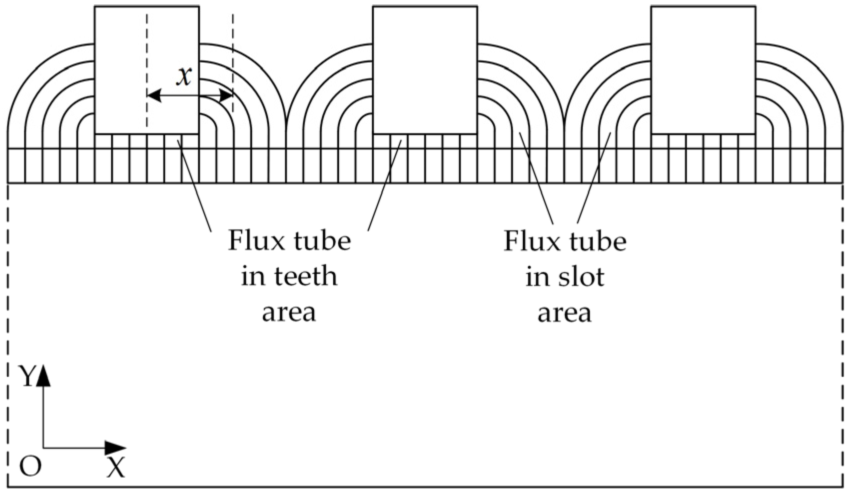
The air-gap flux density is the product of air-gap permeance and armature winding MMF [
19]; however, the permeance calculation is generally difficult in transverse flux motors as the flux distributions are three-dimensional. To avoid that complexity, the space distribution of the permeance can be obtained by using quasi-flux tubes with boundaries determined by straight line and semicircular segments drawn to approximately maximize the permeance of each path [
20], as shown in
Figure 4.
Then, the flux density in teeth area and slot area can be expressed as:
where
hm is the thickness of permanent magnet, δ is the air-gap length, μ
0 is the permeability of vacuum,
N is the armature winding turns,
ia is the instantaneous armature current,
I is the Root-Mean-Square (RMS) of armature current,
ω = 2π
f is the electrical angular velocity and ϕ is the initial phase angle of armature current.
When the high order harmonic component of Equation (1) is neglected, the air-gap flux density can be simplified as:
where
Bmax is the maximum value of air-gap flux density,
Bmin is the minimum value of air-gap flux density, and
k is the modulated factor of armature MMF field.
The imaginary current of permanent magnet [
21] can be expressed as:
where
Br is the residual magnetism of permanent magnet.
Then, the electromagnetic force of each pair permanent magnet and the torque of single phase TFM can be written as:
where
Bal is the air-gap flux density at the position of left boundary of permanent magnet,
Bar is the air-gap flux density at the position of right boundary of permanent magnet,
p is the pole-pair number of TFM, θ is the relative angle when the rotor rotates.
Then, the electromagnetic torque of single phase TFM can be written as:
where
Tmax is the maximum of the single-phase torque, and
Da is the diameter of air-gap.
When the initial phase of armature current ϕ is zero, the amplitude of the single-phase torque reaches the maximum value according to Equation (16), and the electromagnetic torque of each phase can be respectively written as:
and the total electromagnetic torque is:
From Equation (19), the total electromagnetic torque is a constant if the cogging torque and high order harmonics of air-gap flux density are neglected. However, the cogging torque and harmonics of air-gap flux density actually exist in the motor, which will lead to the generation of torque ripple.
3.2. Cogging Torque
The cogging torque is a result of the interaction between core teeth and permanent magnet in permanent magnet motors. Similar to the traditional permanent magnet synchronous motor (PMSM), the proposed CS-TFM contains a teeth-slot structure. The difference between them is that the teeth-slot structure of CS-TFM is on the rotor side instead of the one on the stator side in the PMSM. Therefore, the cogging torque of CS-TFM is caused by the interaction between the permanent magnet and rotor teeth.
The fundamental frequency of the cogging torque is the least common multiple of the rotor teeth number and the stator pole number [
17]; in the CS-TFM, the teeth number is
p and the pole number is
2p. Thus, the fundamental frequency of cogging torque is 2
p and the period is τ
m.
The cogging torque of each single-phase can be expressed as:
where
Ti and θ
i are the amplitude and initial phase angle of the
ith order harmonic, respectively.
Then, the total cogging torque of three-phase TFM is:
Compared to Equations (20) and (21), the harmonic component besides the 3ith order is counteracted, and the amplitude of the three-phase cogging torque is reduced significantly.
4. Three-Dimensional Finite Element Analysis of TFM
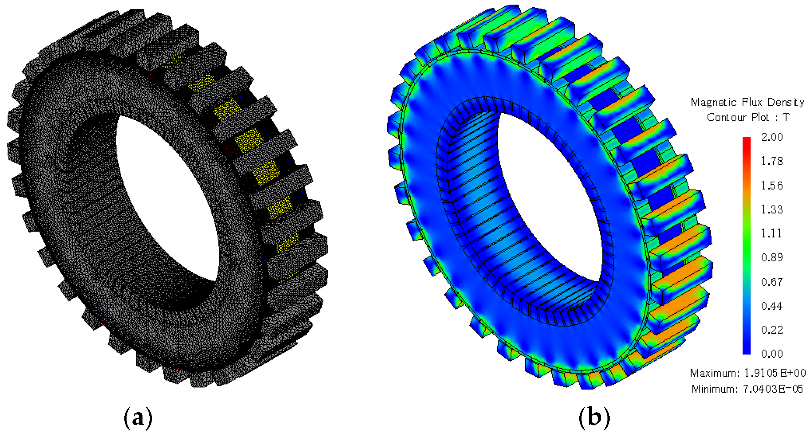
Different from traditional motors, which have 2-D flux paths, the magnetic field is complex and 3D distributional in TFMs, and the 3D FEM is necessary to analyze the electromagnetic characteristic accurately. Although 3D FEM can get accurate results, the calculation time is long when the model is large. As there is no magnetic field coupling between each phase of the TFMs, the single-phase model is built in FEM analysis to reduce the computation time, and the total result can be fitted by three single-phase results with 120° electrical angle difference.
The main design parameters of TFM are shown in
Table 1. The mesh results of model and flux density distribution under load conditions is shown in
Figure 5.
4.1. Air-Gap Flux Density
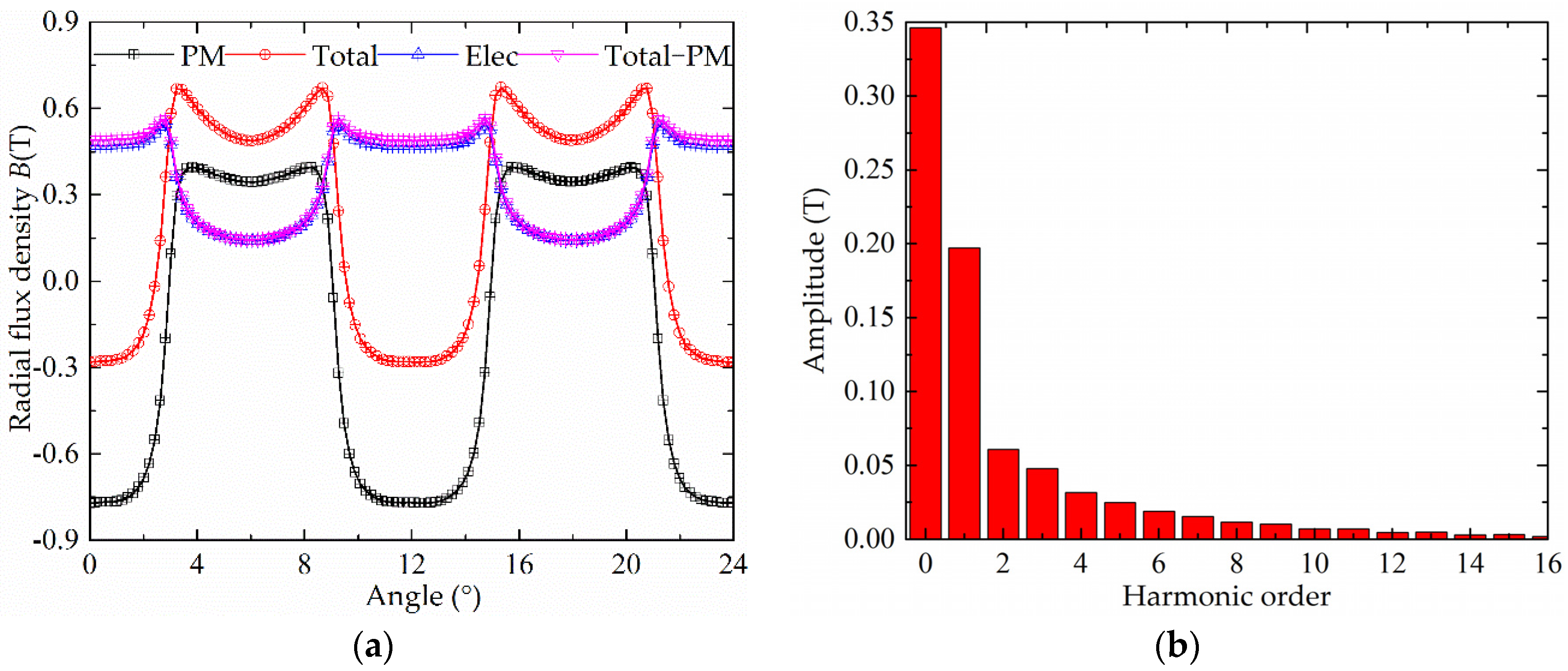
An arc is drawn under two pairs of poles in the air-gap, and the radial flux density on the arc is shown in
Figure 6a: the black line refers to the flux density under no-load condition when the magnetic field is excited by the permanent magnet; the red line refers to the flux density under load condition when the magnetic field is excited by both a permanent magnet and armature current; the blue line refers to the flux density under load condition when the permanent magnet part is replaced by air and the magnetic field is exited only by an armature current; the pink line refers to the difference between the black line and the red line, and it is almost coincident with the blue line. This verifies that the total magnetic field under load condition is comprised of the permanent magnet field and the armature current field.
The harmonic analysis is done to calculate the amplitude of each component by Fast Fourier Transform (FFT), and the results of harmonic analysis regarding the current modulated field are shown in
Figure 6b: the amplitude of fundamental harmonic is 0.197 T, and the constant component is 0.346 T.
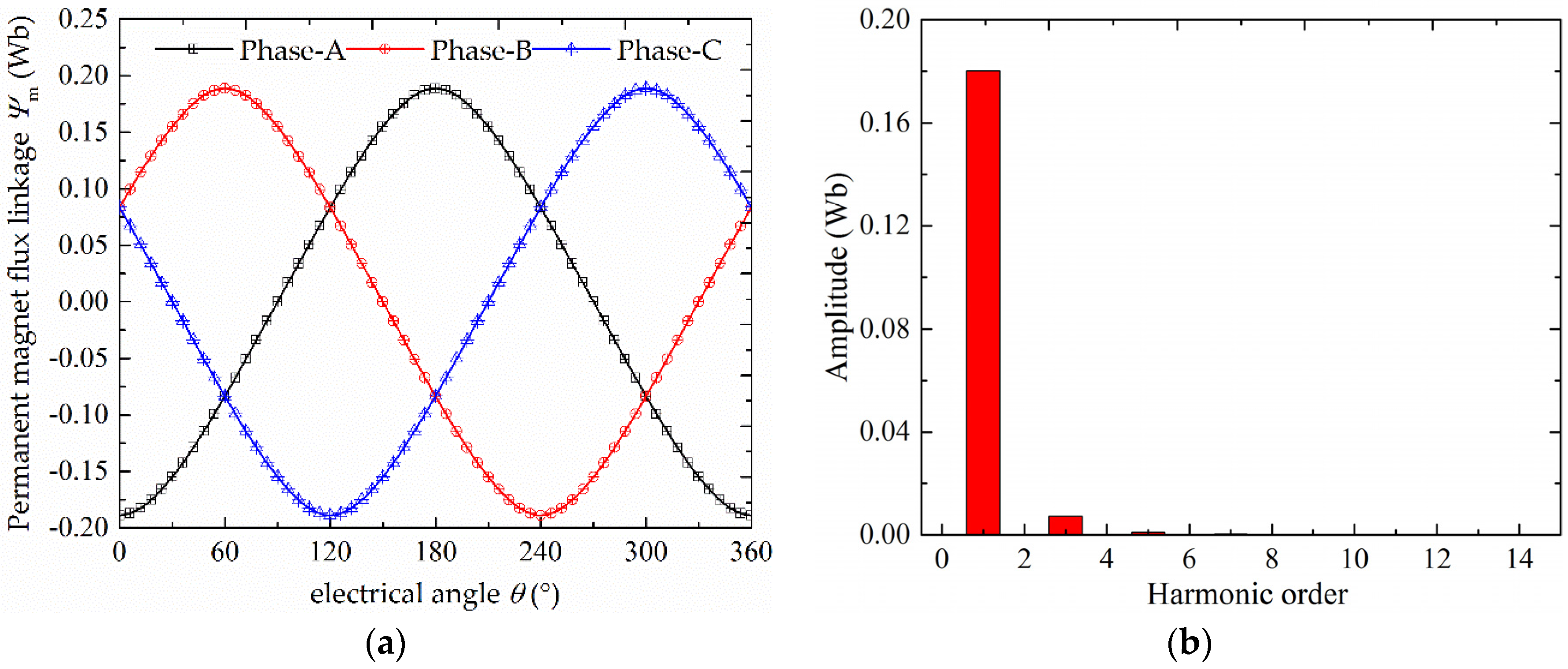
4.2. Permanent Magnet Flux Linkage
The permanent magnet flux linkage waveform in armature winding is shown in
Figure 7a, and the harmonic analysis result is shown in
Figure 7b. It can be seen that the waveform of permanent magnet flux linkage is close to sinusoidal, the amplitude of PM flux linkage is 0.19 Wb, and the total harmonic distortion (THD) is 0.41%.
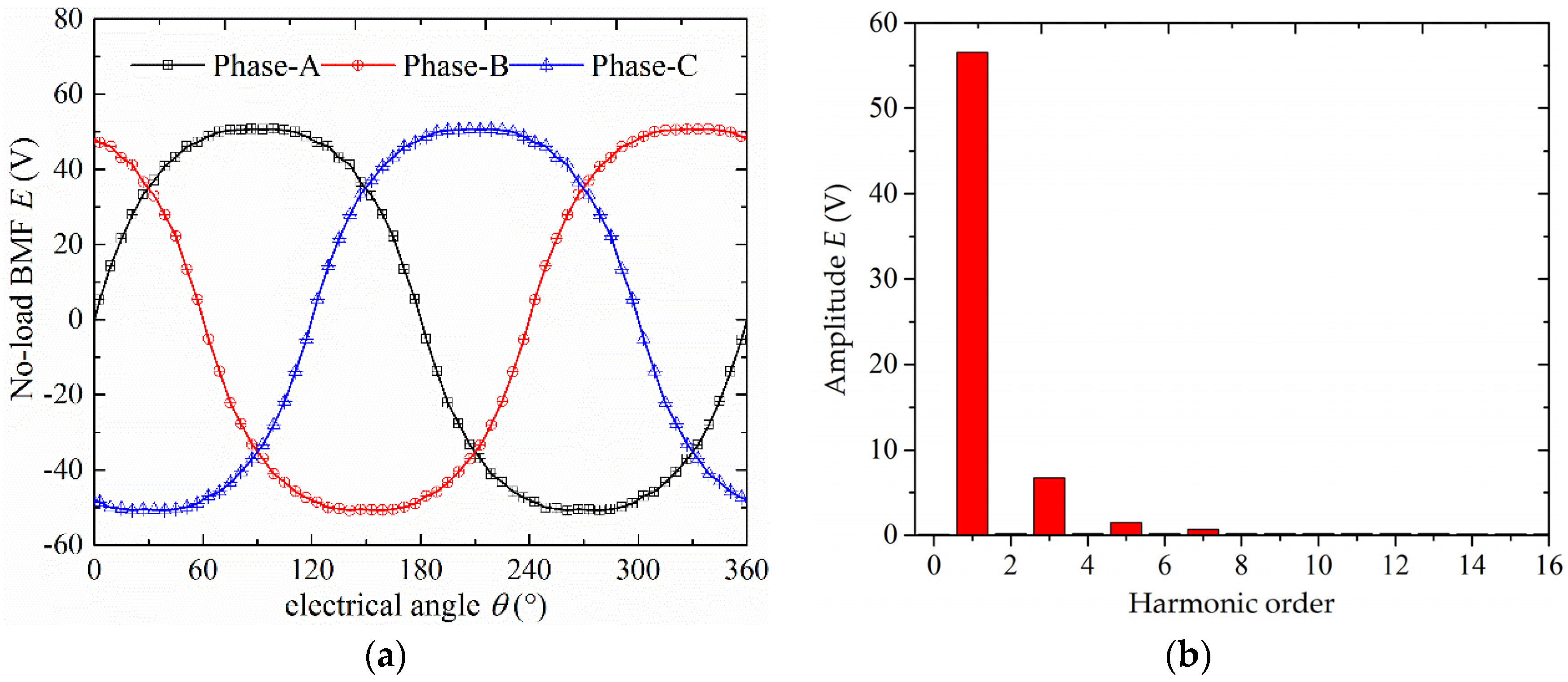
4.3. No-Load BMF
The no-load BMF waveform is shown in
Figure 8a, and the harmonic analysis result is shown in
Figure 8b. The amplitude of no-load BMF under revolving speed 100 r/min is 50.80 V, the amplitude of fundamental component is 56.55 V, and the largest components are the 3rd and 5th harmonics. The THD is 12.39%.
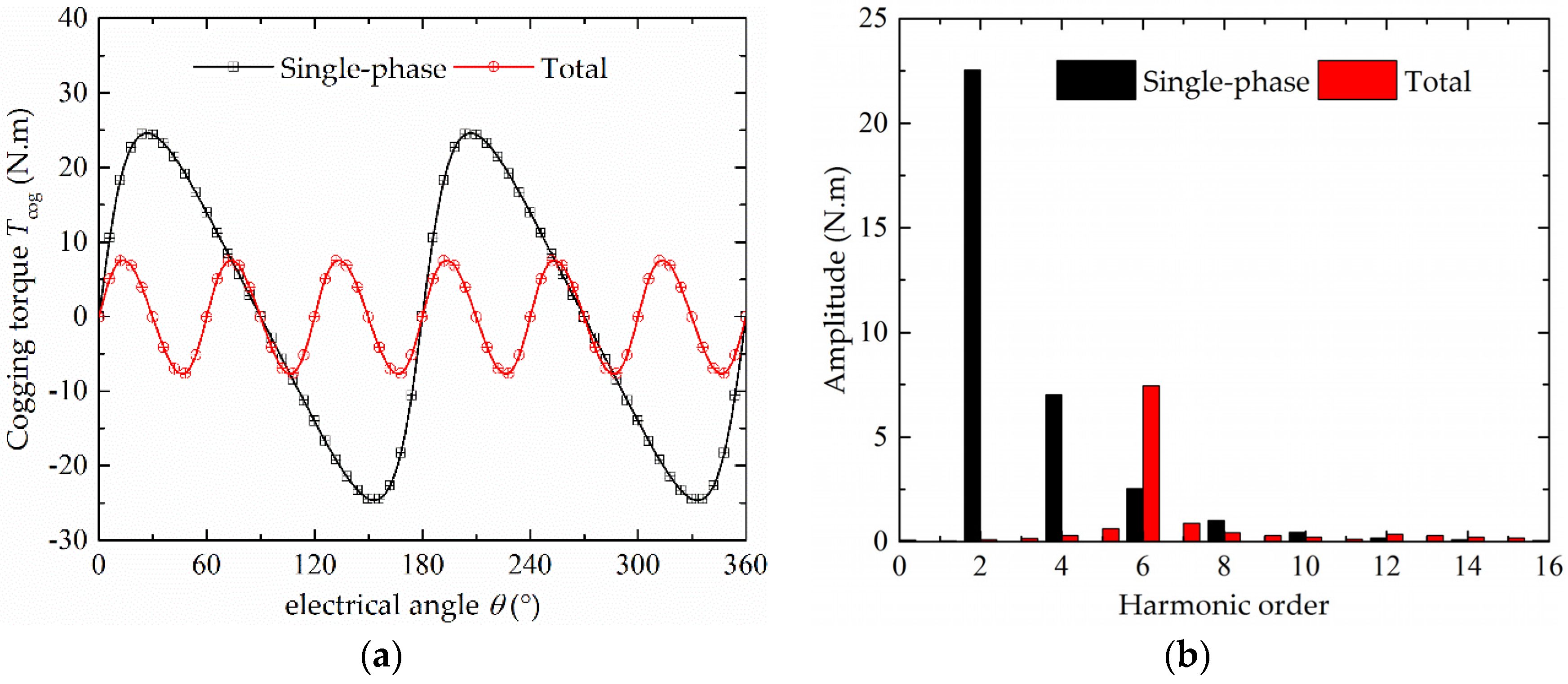
4.4. Cogging Torque
The single-phase cogging torque and total cogging torque waveforms are shown in
Figure 9a, and the harmonic analysis results of them are shown in
Figure 9b.
From the result, the amplitude of the single-phase cogging torque and the total cogging torque are, respectively, 24.43 N m and 7.63 N m. The main components of single-phase cogging torque are the 2nd harmonic, 4th harmonic and 6th harmonic, and the main component of the total cogging torque is the 6th harmonic, which is consistent with the forgoing analysis about them.
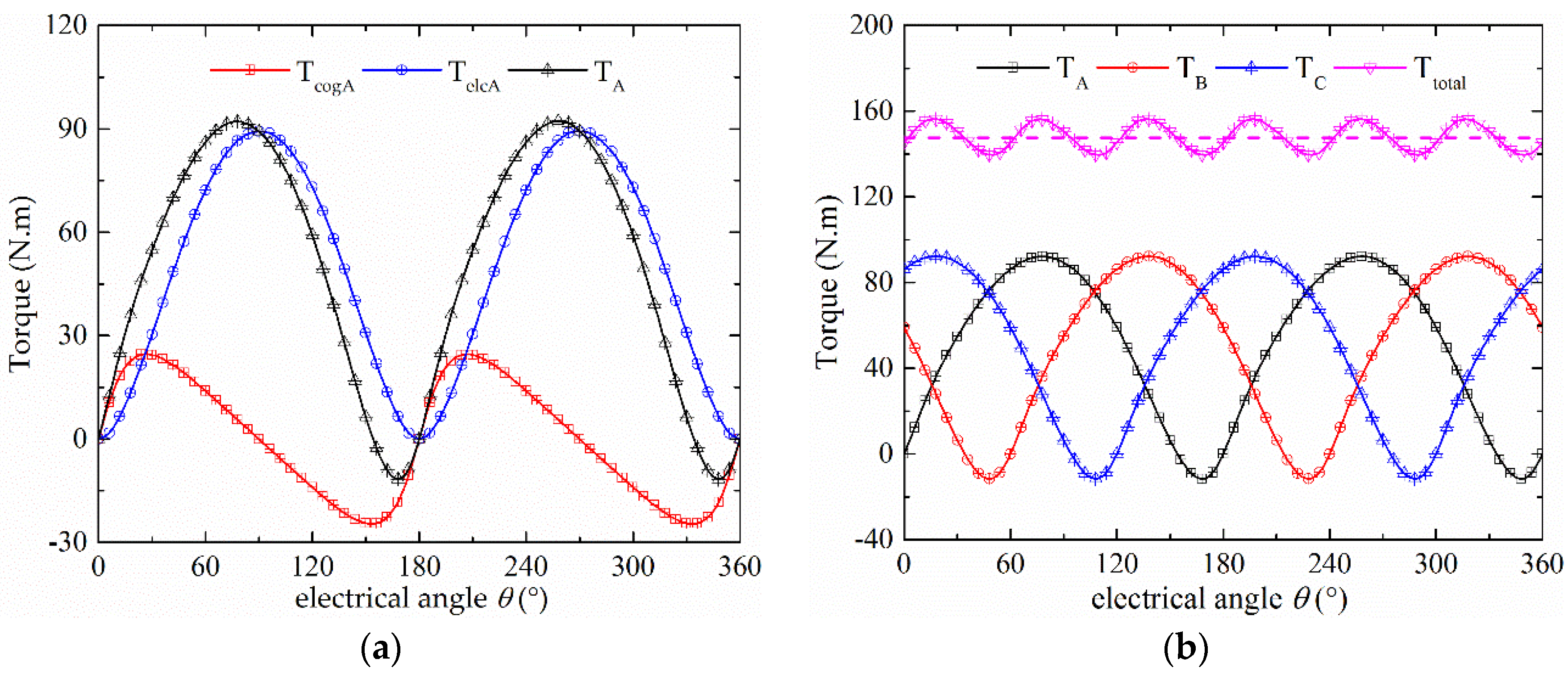
4.5. Torque
The result of single-phase torque is comprised of the cogging torque and electromagnetic torque in the FEM analysis. The electromagnetic torque can be separated out by subtracting the cogging torque from the total single-phase torque, as shown in
Figure 10a.
The electromagnetic torque of single-phase is a nearly pulsating waveform as a result of Equation (16). The total torque waveform of three-phase waveforms is shown in
Figure 10b, the average value is 145.63 N.m, which is approximately 1.5 times of the maximum value of single-phase electromagnetic torque, and the torque ripple is 4.14%.
5. Influence of Structure Parameters on Torque Density
As high torque density is the most attractive advantage of transverse flux motor, the torque density of CS-TFM should be calculated, and the influence of structure parameters on torque density should be analyzed in order to find a useful optimized method for future design process.
The total volume of motor can be expressed as:
Then, the torque density of CS-TFM can be deduced as:
The relationship between pole-pitch and air-gap diameter can be written as:
Then, the torque density of CS-TFM can be expressed as:
From Equation (25), the main influencing factors of torque density are the pole-pitch τm, the thickness of permanent magnet hm, the air-gap length δ and the field modulated factor k. When the out diameter Dout, the air-gap diameter Da and the axial length of motor la are kept as constant, the volume of motor V is a constant. Thus, the torque density corresponds with average torque, and the influence of structure parameters on average torque is analyzed by 3D FEM.
5.1. Pole-Pitch
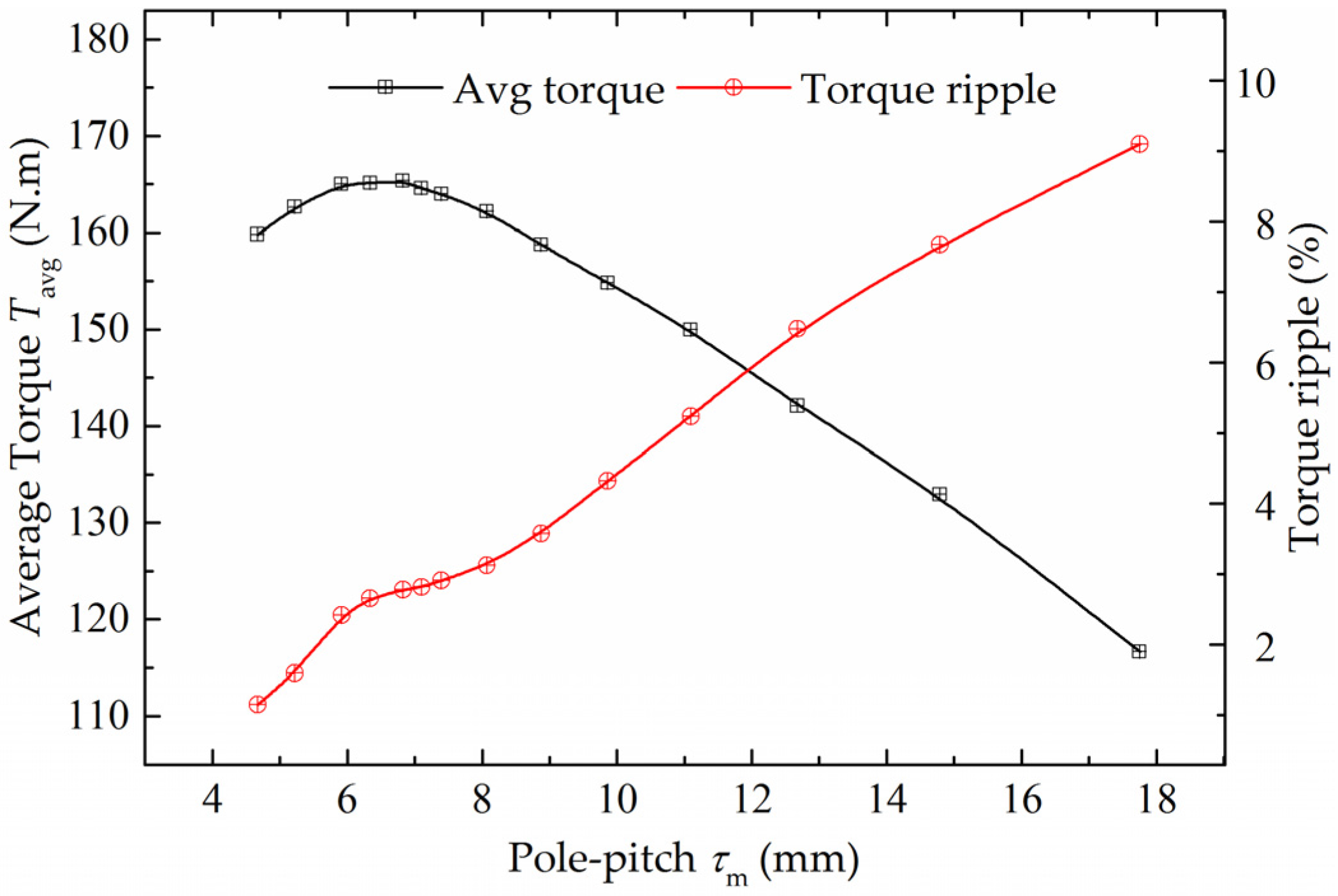
From Equation (25), if the pole-pitch is selected as the unique variable, the torque density of motor will be improved when the pole-pitch is decreased. However, the leakage flux between adjacent permanent magnets will also be increased with the decrease of pole-pitch, which brings a negative influence on the torque density. Thus, there is a reasonable range of pole-pitch.
The pole-pitch τ
m is analyzed as the unique variable by 3D FEM, and the results are shown in
Figure 11. From
Figure 11: (1) the average torque is improved significantly with the decrease of pole-pitch when pole-pitch is larger than 7.3 mm; (2) the average torque is nearly kept constant when pole-pitch is in the range of 5.8–7.3 mm; (3) the average torque is reduced with the decrease of pole-pitch when pole-pitch is smaller than 5.8 mm; and (4) the torque ripple is reduced with the decrease of pole-pitch. The pole-pitch should be chosen in the range of 5.8–7.3 mm from the FEM results.
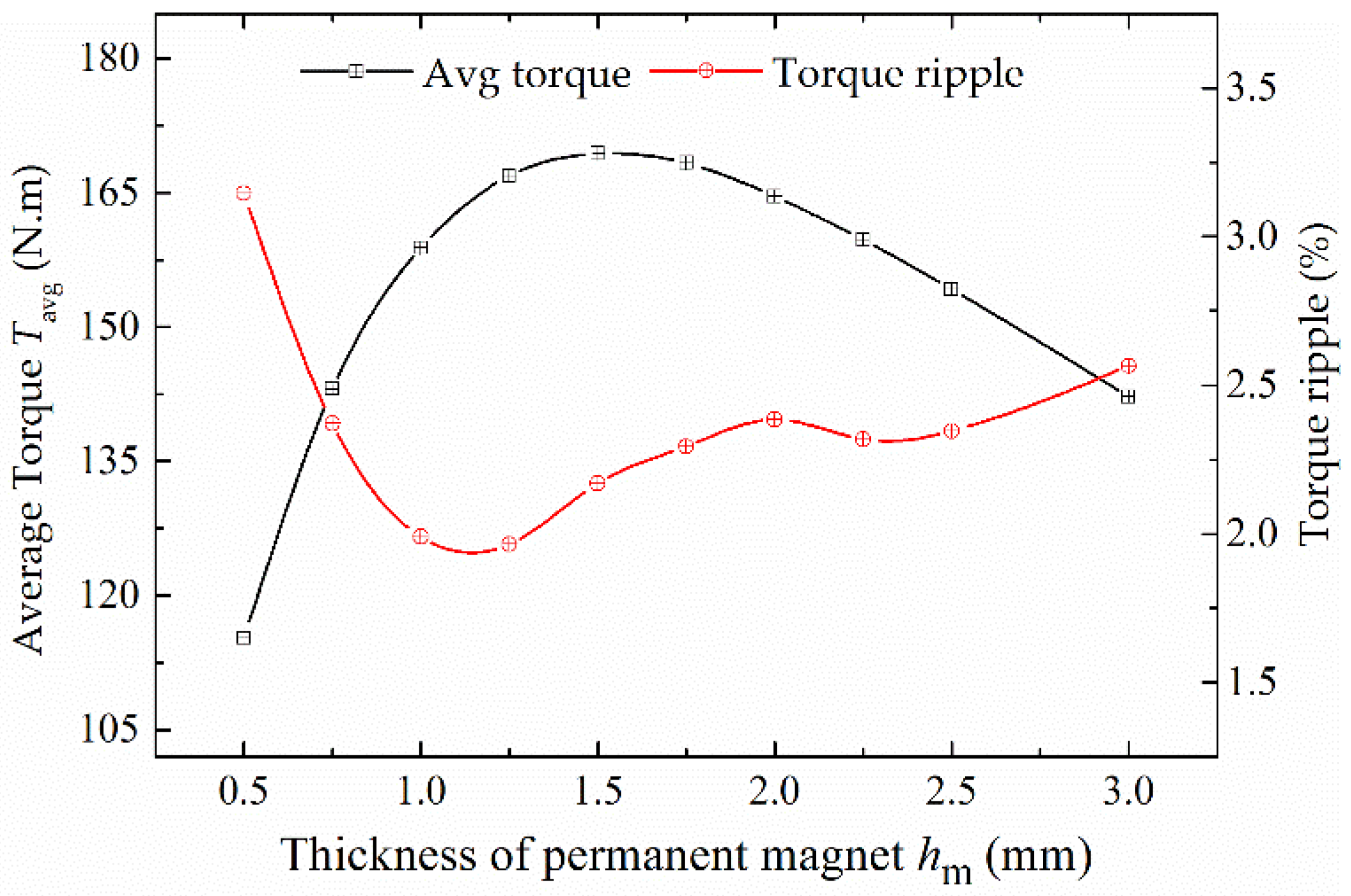
5.2. Thickness of Permanent Magnet
From Equation (8), the maximum value of a modulated field excited by an armature current will be improved when the thickness of permanent magnet is decreased, which brings a positive influence on the torque density. From Equation (11), the amplitude of imaginary current of a permanent magnet will be reduced when the thickness of the permanent magnet is decreased, which brings a negative influence on the torque density. When both positive and negative influences are considered, there is a reasonable range of the thickness of permanent magnet.
The thickness of permanent magnet
hm is analyzed as the unique variable by 3D FEM, and the results are shown in
Figure 12. From
Figure 12: (1) the average torque reaches the maximum value when the thickness is 1.5 mm; and (2) the torque ripple reaches the minimum value when the thickness is 1.25 mm.
In addition, the overload capability of the motor is influenced by the thickness. If the permanent magnet is thin, the core will become more saturated when the motor works under overload conditions, as the equivalent air-gap length is small. Moreover, the permanent magnet is more liable to be irreversibly demagnetized, which is dangerous for the motor. Thus, a larger thickness should be chosen when the overload capability is considered.
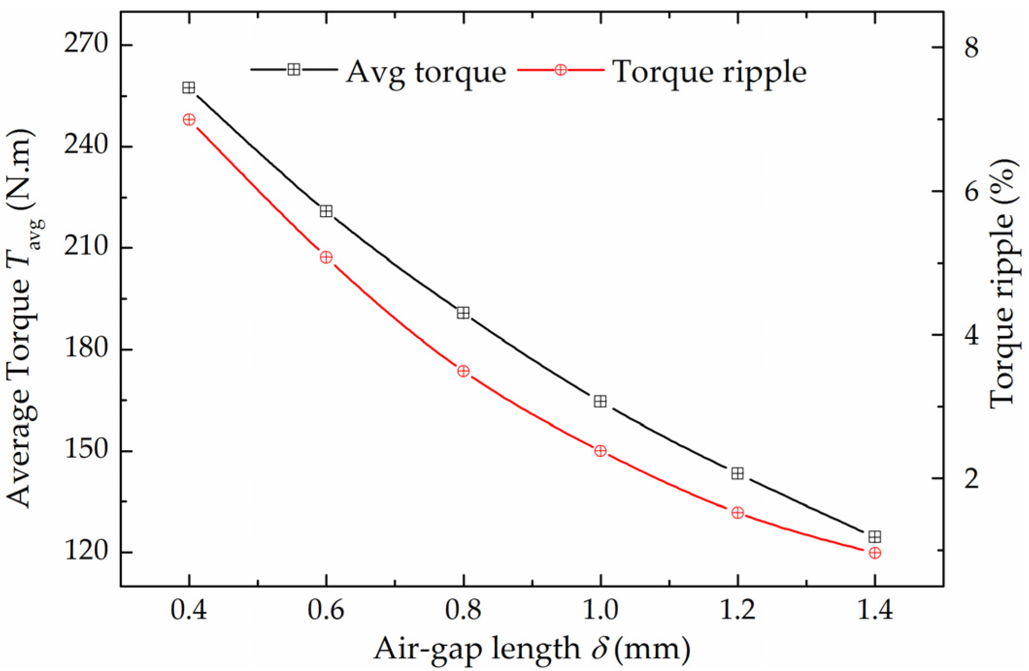
5.3. Air-Gap Length
From Equation (25), the torque density will be improved when the air-gap length is decreased. The air-gap length is analyzed as the unique variable by 3D FEM, and the results are shown in
Figure 13. From
Figure 13, when the air-gap length is decreased from 1.4 mm to 0.4 mm, the average torque is improved significantly. However, the torque ripple is increased at the same time. The average torque under 0.4 mm gap is approximately 1.56 times the one under 1 mm.
In addition, the air-gap length is always limited to the mechanical structure and manufacturing technique, and it should be chosen reasonably under the overall considerations of both working characteristics and machining technique.
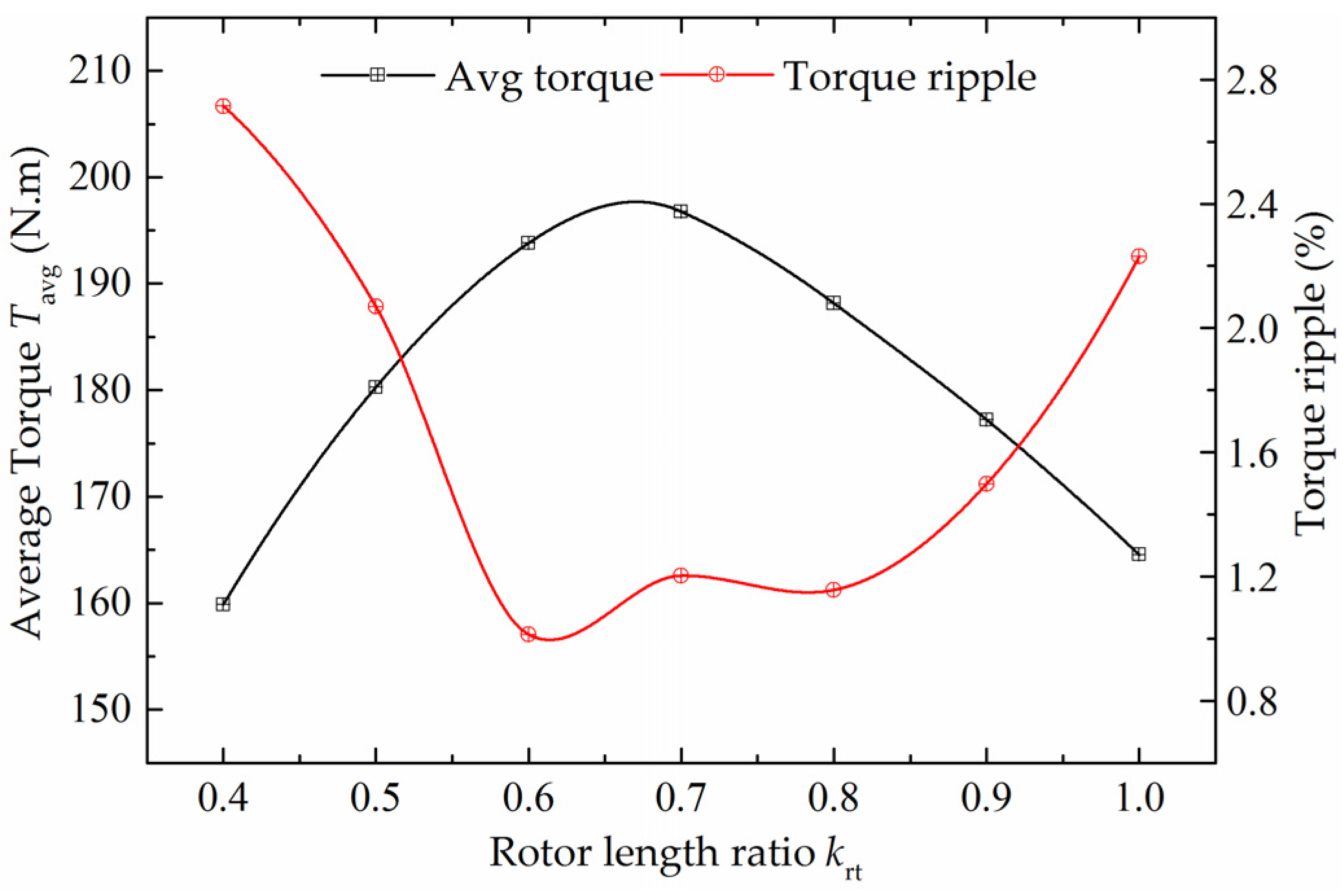
5.4. Circumferential Rotor Teeth Length
Another influencing factor of the torque density is the circumferential rotor teeth length, which influences the modulated field distribution of the armature current field. In order to analyze the circumferential rotor teeth length more conveniently, a rotor teeth ratio is introduced here:
The rotor teeth ratio
krt is analyzed as the unique variable by 3D FEM, and the results are shown in
Figure 14. From
Figure 14, the maximum average torque is generated when the rotor teeth ratio is in the range of 0.6–0.7, and the minimum torque ripple is 0.9% when the ratio is 0.6.
In addition, the overload capability of the motor is influenced by the circumferential rotor teeth length. If the circumferential rotor teeth length is small, the core will become more saturated when the motor works under overload conditions. Thus, a larger rotor teeth ratio should be chosen when the overload capability is considered.
6. Discussion
Based on the analysis results in
Section 5, an optimized CS-TFM is designed and analyzed by 3D FEM, and the comparison between initial model and optimized model is listed in
Table 2. It should be mentioned that the parameters of the optimized model in this section are preliminary optimization results based on the forgoing 3D FEM analysis. A more accurate optimization result can be obtained by using some optimization methods in the motor design process—for example, numerical optimization algorithms or approximate models [
22,
23].
According to the 3D FEM data, when the volume and ampere-turn are kept the same as that of the initial model, the electromagnetic performance of optimized CS-TFM is improved: the amplitude of no-load BMF is increased by 32.84%, the THD of no-load BMF is decreased by 38.09%, the cogging torque is decreased by 56.49%, and the average torque is increased by 29.48%. Meanwhile, the torque ripple is increased from 4.14% to 4.84%.
The torque densities are calculated and compared among various types of direct-drive motors, as shown in
Table 3. The torque density per volume of proposed CS-TFM is higher than BLDC in [
2], TFRM in [
13], and lower than ISDW-PMV in [
5] and TFPM in [
16]. The torque density per permanent magnet volume of CS-TFM is the largest among those motors.
What should be noticed is that the results of torque density are not calculated under similar conditions (air-gap length, rated speed and current density are different from each other). Thus, it is difficult to evaluate the proposed motor simply.
7. Conclusions
An external rotor transverse flux motor is proposed for direct-drive application in this paper. The combined stator core structure makes it possible to use silicon steel sheets in this transverse flux technology, and it improves the mechanical strength and simplifies the manufacturing process of the proposed motor. Both permanent magnet and armature winding of the proposed CS-TFM are fixed on the stator side, and the rotor is only comprised of a core and sleeve. This structure feature improves the reliability of the motor. The theoretical expression of electromagnetic torque is deduced by a field modulated method. Then, the electromagnetic performance of CS-TFM is investigated by 3D FEM, and the results verify the correctness of theoretical analysis. The influences of pole-pitch, PM thickness, air-gap length and rotor teeth length on torque density are analyzed, and the results show that: the pole-pitch, PM thickness and rotor teeth ratio of CS-TFM can be chosen around an optical range of 5.8–7.3 mm, 1.5–2 mm, 0.6–0.7, respectively. The torque density can be improved significantly by decreasing the air-gap length. The performance of a preliminarily optimized CS-TFM is analyzed and compared with the initial one, and the no-load BMF and average torque are increased by 32.84% and 29.48%, respectively. At last, the torque density per volume and per PM volume are calculated, and the results show that the proposed CS-TFM can provide considerable torque density by using few PMs.


