1. Introduction
Selective laser melting (SLM), as an additive manufacturing technology, is mainly used to fabricate small scale and high-precision components [
1,
2,
3,
4]. However, in recent years, large-scale manufacturing has gradually become an important trend of SLM. Until now, the size of the largest available commercial equipment has achieved 800 × 400 × 500 mm
3 (Concept Laser X line 2000R). It is highly likely that SLM can be used to fabricate large-scale components in the near future, such as large scale aerospace titanium components. Compared with other large-scale additive manufacturing technologies based on powder or wire feeding [
5,
6,
7], the predominant advantage of the large-scale SLM lies in the better mechanical properties and higher precision.
However, three problems still severely restrict the development and application of large-scale SLM. The first one is the residual stress [
8], which causes the distortion of components, the difficulty of spreading powder and even the termination of SLM process. The second one is defects, including incomplete fusion defects, and pores, etc. These defects largely reduce the fatigue performance of alloys [
9]. Currently, the residual defects are generally eliminated by post hot isostatic pressing. However, for large-scale components, this method will be difficult and costly. The third one is columnar grains. Although the grain sizes of the alloys fabricated by SLM are fine, the columnar morphology results in mechanical anisotropy, and hence restricts its application.
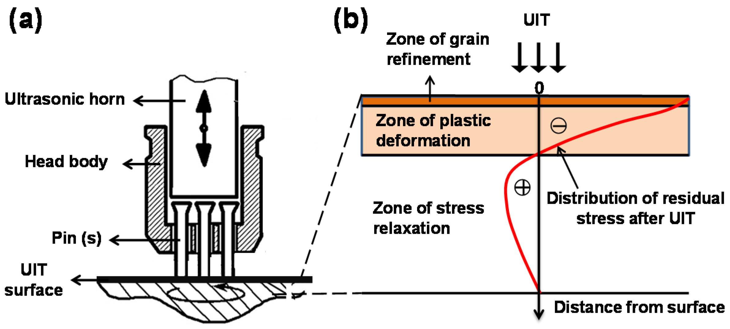
In order to solve the above problems, a novel method is proposed by combining SLM with ultrasonic impact treatment (UIT) technique. UIT is one kind of well-known surface plastic deformation methods (see
Figure 1a), which was originally developed to relax residual stress and improve the fatigue performance of welded structures [
10,
11]. It is usually used for welded processing to eliminate residual tensile stress, and is also used for the surface treatment of bulk material to implant compressive stress and form fine grain zone. UIT can provide a number of beneficial effects on the surface region of alloys by introducing compressive plastic deformation. According to the different treatment effects, the surface can be divided into three zones, as shown in
Figure 1b [
12]: (i) zone of grain refinement at the top surface. Its depth is about 10–30 μm for titanium alloys [
13,
14]. This zone is caused by severe plastic deformation and recrystallization; (ii) zone of plastic deformation with compressive residual stress, but without recrystallization. This zone has a depth of more than 200 μm for titanium alloys [
15]; (iii) zone of stress relaxation with a depth of several millimeters [
12]. For SLM, the thickness of the deposited layer is about 30–200 μm. Therefore, it is hopeful that UIT can effectively reduce the residual stresses, and may eliminate the defects and break the columnar grains. In addition, because the UIT impact head is small, it is suitable to be integrated into large-scale equipment of SLM. Based on these considerations, we explore the feasibility of UIT assisted SLM in this study. A preliminary investigation is undertaken to determine the effect of UIT on the residual stress, defects and grains of Ti-6Al-4V titanium alloy samples.
2. Materials and Methods
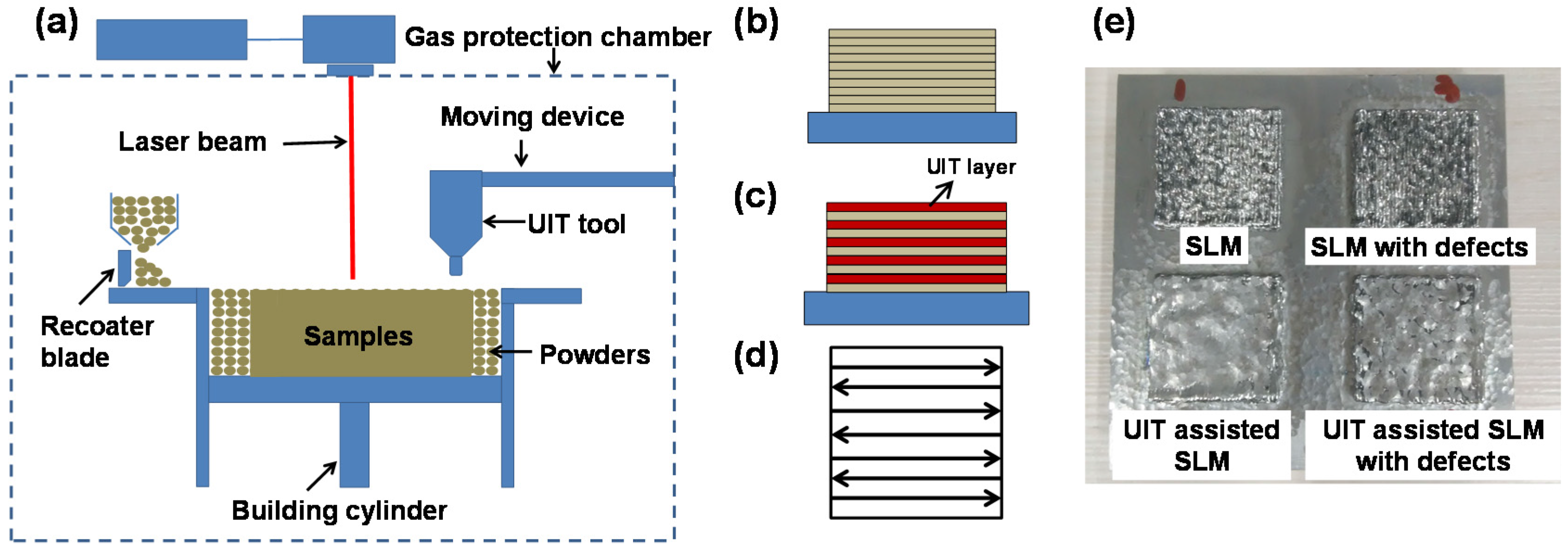
The UIT impact head was integrated into the self-developed SLM system as schematically shown in
Figure 2a. The gas atomized Ti6Al4V powder with a size range of 53–106 μm supplied by AVIC BIAM was used in the experiments. The average particle size of powder is 68 μm (d10:57 μm, d90:95 μm) and the apparent density of powder is 2.48 g/cm
3. Four Ti-6Al-4V samples about 30 mm × 30 mm × 2 mm (10 layers) were fabricated, including SLM samples without and with defects, UIT assisted SLM samples without and with defects as shown in
Figure 2e.
A fiber laser (YLR-WC, IPG Photonics Corporation, Oxford, MA, USA) with a maximum power of 500 W in continuous laser mode is used for the equipment. The size of the build envelop is Φ200 × 100, platform is at room temperature (25 °C). The working chamber provides a closed environment which is filled with Argon as a protective gas to maintain the content of oxygen below 50 ppm. Because the final purpose of this study is to fabricate large-scale components, the SLM process parameters were chosen to ensure high-efficiency. Here, laser power is 400 W, a spot size is approximately 200 µm, a laser wavelength is 1074 nm, scanning speed is 50 mm/s, hatch spacing is 0.6 mm, and layer thickness is 200 μm. The strategy for the fabrication of the cubic specimens is cross-hatching technique. Note that it is difficult to observe the defects in UIT assisted SLM sample, because the density of SLM sample has reached 99.9%. Hence, we compare the SLM sample with defects and UIT assisted SLM sample with defects, in order to study the effect of UIT on the defects. When fabricating SLM sample with defects, the hatch spacing was changed to be 0.8 mm on purpose. During UIT processing, the dimensions of the UIT head is Φ5 mm, the output frequency is 20 KHz and output power is 0.8 kW. Moreover, the moving velocity of the impact head was about 50 mm/min, and the SLM samples were treated once by UIT when the surface temperature is lower than 50 °C after every 2 layers were deposited, as shown in
Figure 2c. Each impacted layer took about 4 min and the scanning path of UIT head looks like “Z”, as illustrated in
Figure 2d.
Metallographic specimens were prepared by conventional mechanical polishing method. A mixture of 1 mL HF, 6 mL HNO3 and 100 mL H2O was used as the etching agent. The surface morphology and microstructures of the samples were characterized by optical microscopy (OM) and scanning electron microscopy (SEM). The β grain size was measured using the metallographic image analysis software SISC IAS v8.0. The quantitative measurement was conducted on at least five OM micrographs with a magnification of 200 for each specimen. The residual stress at the top surface was measured by using the hole-drilling method of ASTM standard E837. The diameter of the hole is 1.5 mm and the depth is 2 mm, the residual stress is calculated according to the measured release of the strain during the drilling process.
3. Results and Discussion
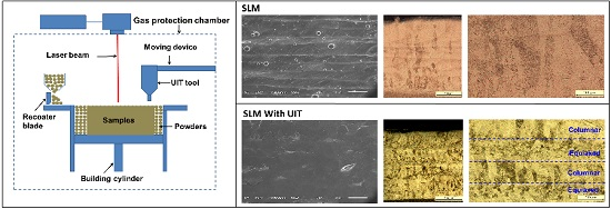
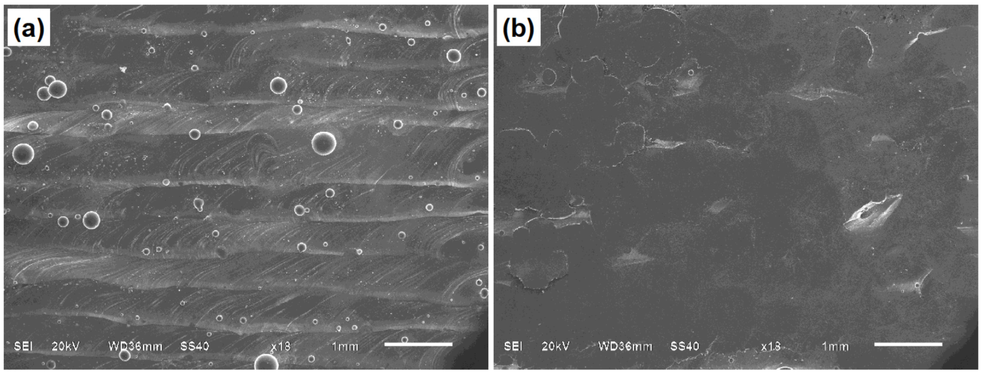
The top surface morphologies of SLM sample and UIT assisted SLM sample are presented in
Figure 3.
Figure 3a shows the multi-track morphology on the surface of the SLM sample. There are a lot of spattering powder particles on the surface. Comparatively, the surface of UIT assisted SLM sample is more smooth. It is hard to observe beads and spatter as shown in
Figure 3b. Obviously, the compressive plastic deformation produced by UIT optimizes the surface morphology, and the smooth surface is helpful to reduce the defects.
The average residual stresses of the SLM sample and UIT assisted SLM sample without defects are 176.3 MPa and 49.9 MPa, respectively. This clearly shows that the UIT assisted SLM process has a significant advantage of reducing residual stress, and the residual stress value can be largely reduced. The reasons can be simply explained as follows. The rapid solidification and high temperature gradient lead to the generation of residual stresses in SLM fabricated sample. According to the solidification shrinkage and temperature gradient mechanism [
8], tensile residual stresses exist in new deposited layers. UIT can introduce the compressive stress into the layer, and hence reduce the tensile stress.
Figure 4a shows that there are many large and irregular incomplete fusion defects in the SLM sample, due to the inappropriate hatch spacing [
16] (used on purpose to generate defects). However, since UIT is applied after depositing every two layers, some small defects are basically eliminated. Meanwhile, large defects are hammered flat, showing a trend of closure, as shown in
Figure 4b. We can clearly see from this comparison that UIT plays a significant role in reducing defects. This is due to the compressive surface plastic deformation caused by UIT. It should be noted that, during the long time SLM additive manufacturing of large-scale components, defects (pores, etc.) are unavoidable. These defects largely reduce the fatigue performance of alloys [
9]. However, our above results suggest that UIT assisted SLM may be used to obtain the full density components. Therefore, the costly post hot isostatic pressing method can be avoided.
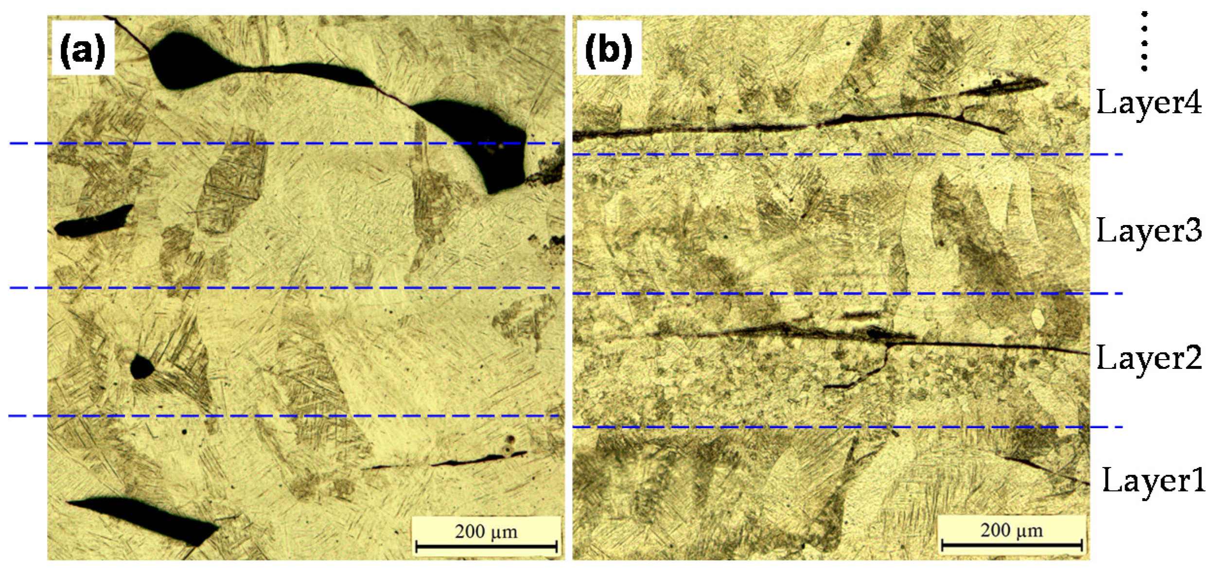
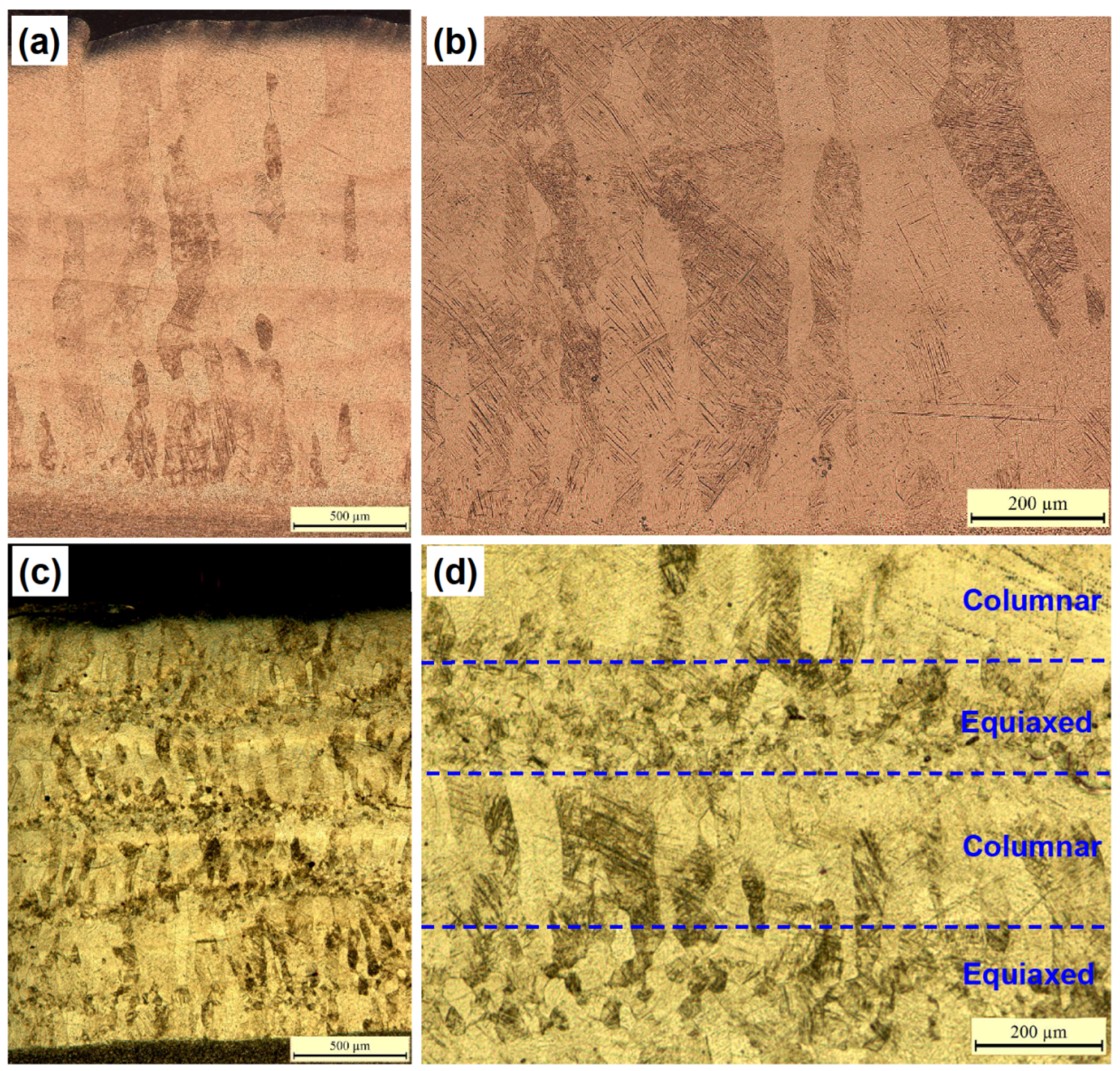
For the SLM sample, long columnar β grains dominate in the sample with the average width about 100 μm as shown in
Figure 5a,b. For the UIT assisted SLM sample, it consists of fine equiaxed grains with the diameter about 20 μm, and short columnar grains with the width about 50 μm and height about 250 μm as shown in
Figure 5c,d. Meanwhile, it is interesting to find that the columnar grains and equiaxed grains are distributed alternately, forming a novel bamboo-like morphology (see
Figure 5d). Besides, the height of these bamboo-like grains is about 400 μm, which is identical to the thickness of 2 layers. Considering that the sample was treated once by UIT every 2 layers, this morphology implies that the formation of fine equiaxed grains is associated with UIT.
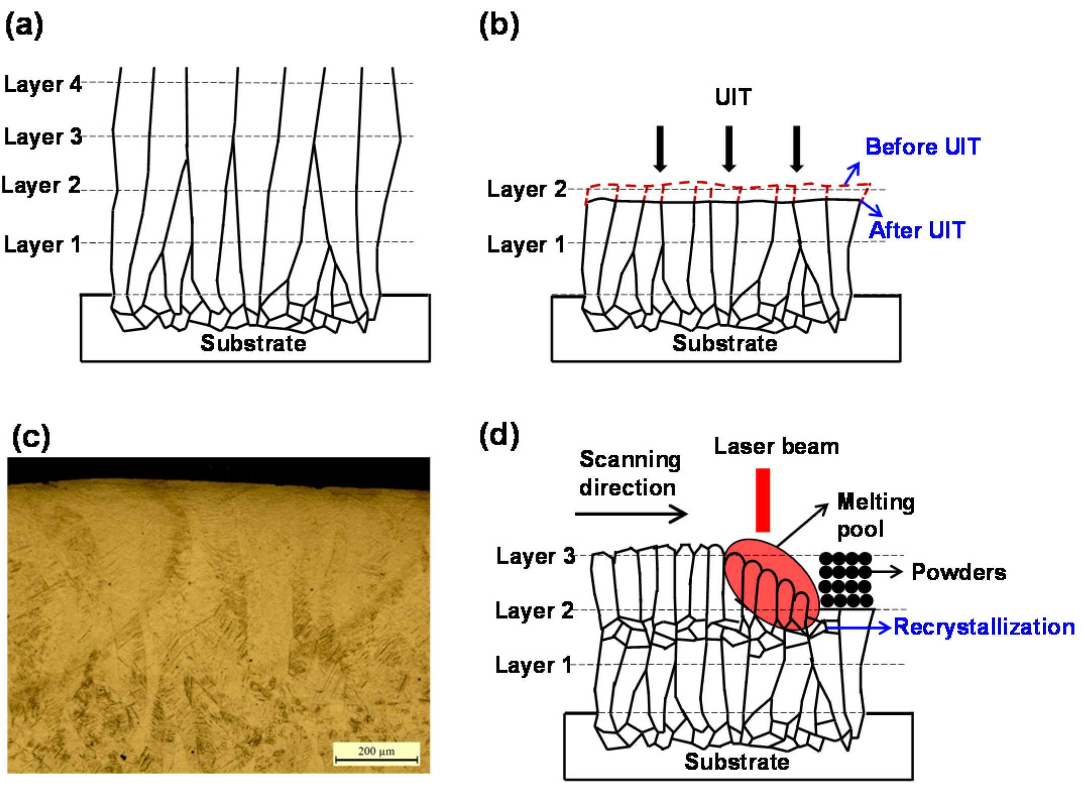
Next, the grain evolution during UIT assisted SLM is proposed as shown in
Figure 6. Firstly, during SLM process, there is high temperature gradient due to rapid heat loss through the substrate or previously deposited layers. This results in the epitaxial growth of β grains as schematically shown in
Figure 6a [
5,
17], and hence leads to the long columnar grain morphology in SLM samples (see
Figure 5a). During UIT assisted SLM process, when layer 1 and 2 (counting from the bottom layer) are deposited, the columnar grains are also formed. Then, the UIT is applied. Compressive plastic deformation occurs in the surface region as schematically shown in
Figure 6b. There are two possible mechanisms for the formation of fine equiaxed grains. One is dynamic recrystallization, which occurs during heavily plastic deformation. The other is reheating and recrystallization. In this case, the sample may also be subjected to some extent of deformation, but the deformation extent is not high enough to directly induce recrystallization. Here, dynamic recrystallization is thought to be not the key mechanism due to the following two clues. Firstly, according to previous research, the depth of dynamic recrystallization zone (i.e., zone of grain refinement in
Figure 1b) is generally only about 10–30 μm [
13,
14], which is too thin to be observed. Meanwhile, it can be completely remelted during the depositing of next layer. Furthermore, the depth of the equiaxed grain regions observed in
Figure 5d is significantly larger than this value. Secondly, dynamic recrystallization can results in very fine grain size (about 20–100 nm) [
13,
14]. However, the averaged equiaxed grain size is about 20 μm. Accordingly, it can be inferred that the fine equiaxed grains generate in the plastic deformation zone, because the compressive plastic deformation can induce high dislocation density and internal energy storage in this zone. During the depositing of Layer 3 (see
Figure 6d), the rapid heating will lead to the recrystallization in the heat treated zone under the melting pool. Therefore, the fine equiaxed grains gradually form, and the grain morphology turns to be bamboo-like.


