1. Introduction
Within the aerospace industry there is a constant drive to produce more environmentally friendly aircraft. Although at present the aerospace sector is not a major contributor to greenhouse emissions, historical trends show that global air travel is doubling every fifteen years [
1]. One way of reducing the environmental impact of such an increase in air travel is to produce aircraft that are lighter in mass through the use of advanced composite materials and construction techniques which provide improved strength and stiffness to weight ratios when compared to traditional materials and methods.
Aircraft structures are typically constructed from thin load bearing skins with stiffeners attached to provide the structure with the required amount of rigidity [
2]. There are two predominant methods of attaching the stiffeners to the skin; mechanical fasteners such as rivets, or bonding with an adhesive. Traditionally, mechanical fasteners have been used in primary structure of the aircraft (
i.e., the structure in which failure would be catastrophic) because of their ability to transfer loads between components with predictable performance. However mechanical fasteners create high stress concentrations which can lead to crack initiation [
3,
4].
Adhesively bonded metallic joints have been used in the secondary structure of aircraft for the past fifty years [
5]. Bonding stiffeners to the aircraft’s skin is advantageous when compared to riveting as it can reduce the mass of the joints, distribute the stresses more evenly and be more resistant to environmental effects (such as temperature, humidity and vibration) which an aircraft experiences [
6]. Adhesively bonding stiffeners is also less labour intensive and more cost effective than using mechanical fasteners as it does not require the structure to go through repetitive drilling operations [
7]. Adhesive bonding is particularly suited to composite structures where the use of mechanical fasteners presents additional difficulties. Due to the hardness and high tensile strengths of some composites, drilling can cause rapid deterioration of the drill bits [
8] resulting in high machining costs and thus skilled operatives are required to carry out the operation. Drilling can also cause damage to the composite such as interlaminar crack propagation, micro cracking, fibre breakage, fibre pull-out, matrix cracking, thermal damage and delaminations. The presence of the hole also forms a reduction in the strength of the material due to the fibres no longer being continuous.
Though adhesives bonds have been used in the secondary structure without arrestment fasteners (
i.e., fasteners that would still bear the load should the adhesive fail) they are rarely used in the primary structure without the use of arrestment fasteners due to the lack of confidence in the reliability of the joint [
9]. From the experience of the Royal Australian Air Force (RAAF) 53% of defects detected in aircraft structures such as the F-111 were found to be bond failures [
10]. Many cases of adhesive bond failure have been found to be the result of improper application of the adhesive or insufficient surface preparation [
9]
i.e., human error in the manufacture of the joint.
Though it has been proven that bonded joints are more resistant to fatigue loading as well as being able to withstand higher peak loading [
10], the degradation of the adhesive layer over time is not yet fully understood [
11]. This uncertainty in the condition of the bond throughout the aircraft’s in-service life requires monitoring using non-destructive techniques to ensure airworthiness. Traditional non-destructive (NDT) techniques can be used to inspect the structural integrity of bonds on aircraft structures. However with the increasing size of commercial aircraft, the influence of human error and pressures from aircraft operators to reduce maintenance times [
12], alternative solutions to traditional NDT techniques have to be found to enable the application of airworthy adhesively bonded stiffeners. If a sensor network could be installed to monitor damage and degradation of the bonded joint an “as required” inspection program could be used. The most straightforward method of implementing such a structural health (SHM) network onto an aircraft is during the design stage [
13]. It has been suggested that by implementing structural health monitoring during design, weight savings of up to 15% could be achieved at component level [
14].
A long-established technique for detecting damage in structures is by using acousto-ultrasonic induced Lamb waves. The principle involves exciting a piezoelectric transducer mounted to the structure’s surface which induces a Lamb wave that is then detected by another transducer mounted at a different location on the structure. If damage occurs within the field between the two sensors, the signal propagation is altered resulting in a quantifiable difference in the signal received. This technique can be extended to networks of multiple sensors to improve detection capability.
To enable complex adhesive bond defects such as kissing bonds (where bond fails but still remains in close contact with the bond face hence appearing to still be bonded. These are notoriously difficult to detect [
15]) to be detected using acousto-ultrasonic techniques, sensor networks need a high probability of detection. An understanding of Lamb wave interaction with stiffeners and their defects will enable better sensor network design whilst also driving towards minimizing the weight penalty the sensors add to the overall structure.
Following a review of the use of Lamb waves in SHM and their study using laser vibrometry, this paper presents the results of an experimental investigation of the interaction of Lamb waves with adhesively bonded stiffeners (with and without disbonds) using 3D scanning laser vibrometry. Results demonstrating Lamb wave interaction are shown, together with post-processing of the vibrometry data with a windowed root-mean-square technique. The results are further compared with the results of ultrasonic inspection of the disbond and its associated geometry is shown to correlate very closely with disturbances of the Lamb waves as they interact with the stiffener and the damage, demonstrating the power of Lamb wave-based SHM systems to detect the presence of adhesive failure.
2. Lamb Waves
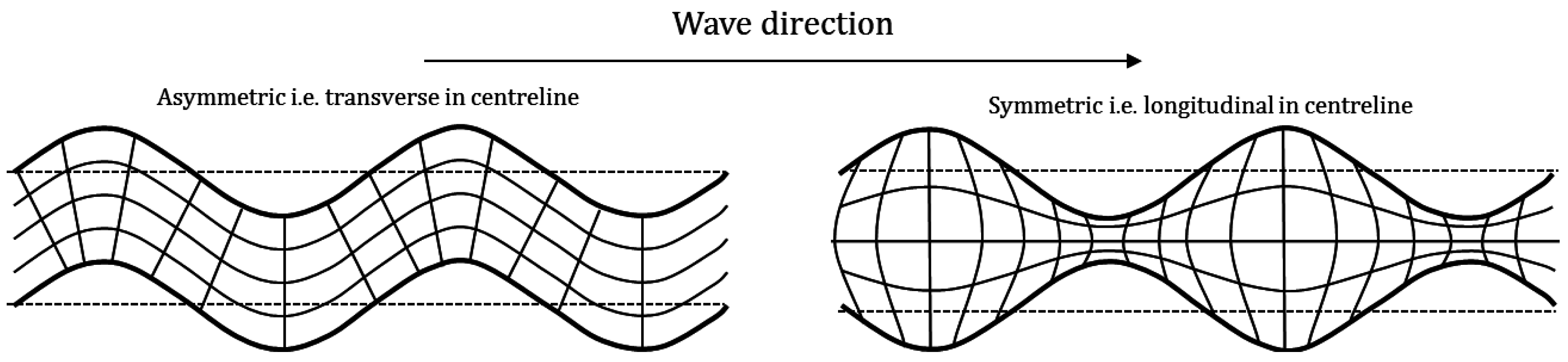
Lamb waves are traction free surface waves that are induced in thin plates. There are two main types of modes of Lamb wave, the symmetrical (S) modes which can be represented by cosine functions and the asymmetric (A) modes which can be represented by sine functions. A diagrammatic presentation of these two wave modes are presented in
Figure 1. The full numerical solutions are presented in [
16].
Theoretically there are an infinite number of number of wave modes [
17]. Though high order modes have shown potential for monitoring structures, particularly for small defects in their microstructure, their low amplitudes [
18] and higher frequency content mean that they experience greater attenuation limiting their use in SHM systems [
19]. It is for this reason that for monitoring larger structures the S
0 and A
0 modes are only typically excited in an SHM system to reduce the number of sensors required and limit the processing costs.
Figure 1.
A diagrammatic representation of symmetrical and antisymmetric wave modes.
Figure 1.
A diagrammatic representation of symmetrical and antisymmetric wave modes.
Lamb waves exhibit a phenomenon known as dispersion where the velocity of the wave through a plate is a function of its frequency [
20]. Typically, the symmetrical mode has a higher wave velocity than the antisymmetric mode of the same order. Due to velocity and wavelength being a function of the frequency of a Lamb wave, excitation frequency is an important consideration for pulse-receive type SHM systems.
There have been extensive studies carried out on the behaviour of Lamb waves in plate like structures [
21,
22]. A comprehensive experimental study supported by mathematical prediction of Lamb wave behaviour in metallic plate-like structures with adhesively bonded joints was performed by Rokhlin [
23]. This work investigated the Lamb wave interaction and transmission through lap-shear joints. Mode conversion was studied as the primary phenomena to determine the condition of the joint. This work goes some distance towards determining appropriate modes and frequencies to be used for inspecting the condition of adhesively bonded lap shear joints. However, it only considered higher order wave modes for detecting the presence of disbonds [
23].
The mechanics and theory behind the reflection and transmission of plate waves by vertical stiffeners was presented in [
24]. This work highlights the complexity of Lamb wave interaction with vertical stiffeners. As Lamb waves interact with a stiffener some of the wave energy is transmitted through the stiffener while a percentage of the wave energy is reflected by the stiffener back towards the source and a small amount is attenuated by the stiffener. As a Lamb wave interacts with an adhesively bonded stiffener, it is possible for mode conversion to also occur due to changes in thickness and hence boundary conditions. This was numerically investigated using a boundary element method and further experimentally investigated by Cho [
25]. Cho demonstrated that changes in thickness, particularly through a joint or a change in thickness due to a defect can result in different guided wave behaviours including reflection, transmission and mode conversion. Lemistre and Balageas [
26] also experimentally investigated the mode conversion phenomenon of Lamb waves interacting with a delamination in a composite panel based on a working hypothesis derived from the work of Han
et al. [
27]. The work demonstrated that the diffraction effect exhibited by interaction with the defect did indeed induce mode conversion. It is also possible for mode conversion to occur at other changes in acoustic impedance [
28] such as a change in material (
i.e., interaction with adhesive layer). Changes in wave mode can cause issues with the detection of Lamb waves, in particular for systems that primarily detect one wave component.
Ramadas
et al. [
29] numerically investigated the interaction of the fundamental antisymmetric mode with a bonded stiffened section made from glass fibre reinforce plastic. Transmitters and receivers were positioned on different sections of the structure to investigate the turning modes as the A
0 interacted with the structural discontinuity. The numerical simulations were validated with experimental data and it was found that the interaction resulted in a fundamental symmetrical mode being generated. It is worth noting that this work only considered the stiffened region of the plate and did not consider the full transmission of the Lamb wave through the stiffened section.
Generally, Lamb waves exhibit different and usually more complex behaviour in composites compared to metallic materials due to weave and fibre orientation. This makes the problem of implementing an SHM system more difficult. Traditionally, in metallic aircraft structures stiffeners are not bonded but are attached using mechanical fastening methods whereas composite stiffeners are either bonded or are integral to the structure. To reduce the complexity in both the Lamb wave behaviour and specimen design in this investigation, a metallic stiffener bonded to a metallic plate is considered with a view to applying the techniques presented to more complex composite components in future work.
3. Lamb Wave Measurement Using 3D Laser Vibrometry
One of the earliest set of studies to use scanning laser vibrometry to sense Lamb waves and their interaction with damage was presented in [
30,
31,
32]. In these studies, 1D scanning laser vibrometry was used to measure the out-of-plane velocities of A
0 Lamb wave propagation through aluminium plates with various defects. The Vibrometry data recorded was validated using the responses of piezoelectric transducers bonded to the surface. Numerical simulations were also found using the local interaction simulation analysis (LISA). This set of studies demonstrated the potential of using scanning laser vibrometry for investigating Lamb wave propagation and interaction with damage.
Out-of-plane scanning laser Doppler vibrometry has been previously used to successfully detect damage in a stiffened panel [
33]. Experimental work was carried out to detect the voids left by the absence of rivets used to attach a t-shaped aluminium stiffener to a flat aluminium plate. The plate was excited by a lead zirconate titanate (PZT) transducer with a 5-cycle sine wave multiplied by a Hann-window at frequencies of 5 kHz, 35 kHz, 100 kHz and random noise. By calculating the route mean square of the signal received at each measurement point it was possible to generate a visualisation that clearly showed the absence of the rivets. The best visualisations were found to be obtained from results taken at higher frequencies.
Out of plane measurements were taken by Sohn
et al. [
34] using a 1D scanning laser vibrometer to measure Lamb wave interaction with delaminations in a composite plate after impact as well as Lamb wave interaction with a disbond of a composite spar. In this work, frequency-wavenumber domain and Laplacian image filters were placed over the wave field images to enhance imaging of the defect. This successfully located the presence of the damage and highlighted the potential for image-based techniques for use in SHM applications.
3D scanning laser vibrometry has served as a successful method for validating results from finite element analysis models by Olson
et al. [
35]. This study demonstrated the capability of 3D scanning laser vibrometry to measure accurately in-plane and out-of-plane Lamb modes in thin plates for SHM applications. The advantages of using 3D scanning laser vibrometer over a 1D system were demonstrated by using the data of the in-plane modes to qualitatively and quantitatively more accurately validate finite element models.
4. Experimental Study
4.1. Panel Manufacture and Geometry
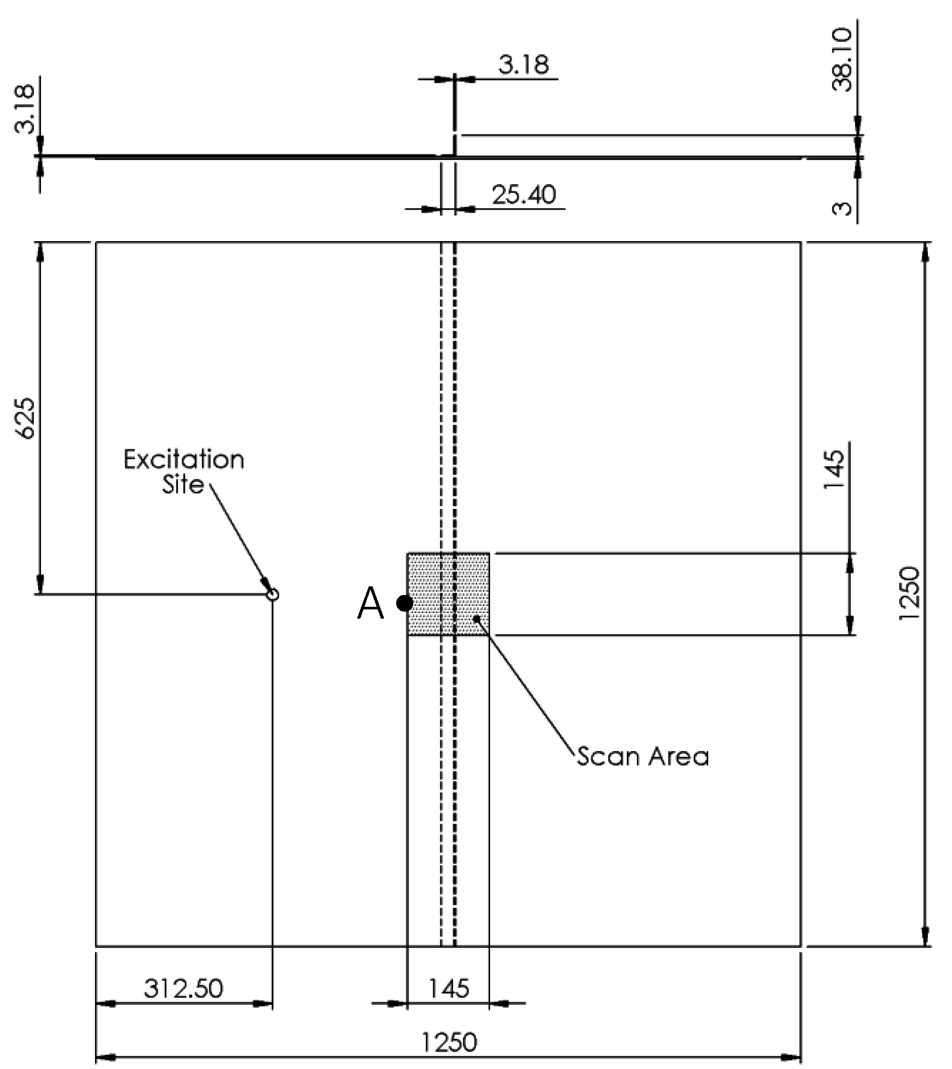
A 3 mm thick 6082-T6 aluminium plate was bonded to a 6082-T6 aluminium unequal angle stiffener to construct a stiffened panel with the dimensions shown in
Figure 2. The dimensions of the panel were chosen to reduce the effects of edge reflections. The stiffener was bonded to the plate using commercially available Araldite
® 420 (Huntsman, Woodlands, TX, USA) adhesive. The film thickness of the adhesive was regulated using 0.1 mm copper wire gauges to achieve the best shear strength [
36].
Figure 2.
Dimensions of the stiffened panel (all dimensions in mm).
Figure 2.
Dimensions of the stiffened panel (all dimensions in mm).
A geometrically similar second panel was also manufactured with an induced disbonded region of 25.4 mm length across the width of the stiffener. The disbonded region was induced by installing PTFE tape prior to applying the adhesive. This was then removed once the adhesive had cured.
A commercially available PANCOM Pico-Z (200 kHz–500 kHz) transducer (PANCOM, Huntingdon, UK) was acoustically coupled to the panel using Loctite
® (Loctite, Düsseldorf, Germany) Ethyl-2-Cyanoacrylate adhesive. This transducer was selected because of its flat broadband frequency response in the frequency range under investigation and its relatively small face (5 mm) as previous studies have shown that sources that are representative of a point source produce good results [
37]. The transducer was located at the mid-point between the panel edge and the stiffener centreline to reduce the effects of edge reflections on the transmitted wave. This also was sufficient distance from the scan area to ensure that that the Lamb waves had fully formed.
4.2. Experimental Setup
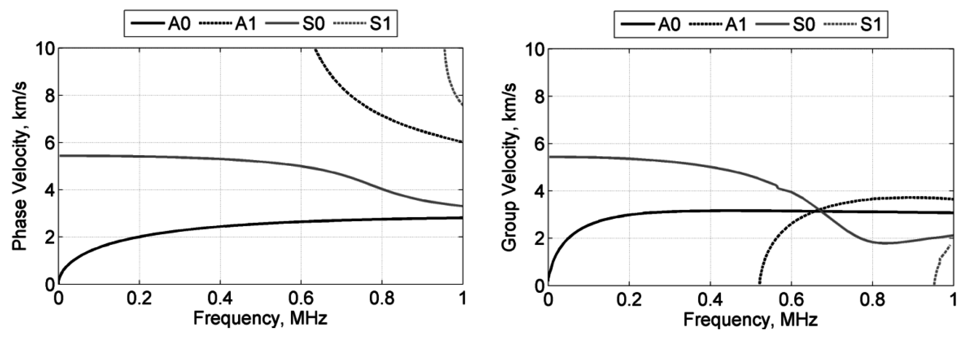
A 10-cycle sine wave was generated by the Mistras Group Limited (MGL) WaveGen function generator software (MGL, Cambridge, UK) which was connected to the MGL μdisp/NB-8 hardware (MGL). This allowed the transducer to input sufficient energy into the structure. The peak-to-peak amplitude of the excitation signal was 160 V. Three frequencies were selected for this experiment; 100 kHz, 250 kHz and 300 kHz. The frequencies investigated primarily excited the two fundamental modes as shown in the calculated dispersion curves for a 3 mm aluminium plate in
Figure 3.
100 kHz was chosen to investigate how a longer wavelength interacted with the stiffener and the disbonded region. The wavelengths for the A0 and S0 were calculated to be 15 mm and 55 mm respectively. Though this frequency fell outside the operating resonance window of the chosen transducer, the calibration certificate for the transducer showed that it would function at this frequency but at a reduced amplitude. Therefore, frequencies of 250 kHz and 300 kHz were also selected to investigate the interaction of smaller wavelengths. The wavelengths for the A0 and S0 were calculated to be 9 mm and 22 mm respectively for the 250 kHz excitation and 8 mm and 18 mm respectively for the 300 kHz excitation. Frequencies above 300 kHz were not considered due to the constraint of the sampling frequency of the acquisition card in the laser vibrometer used. A 10 V peak-to-peak wave was also generated and used as a reference signal for triggering the acquisition of the vibrometer. A repetitive trigger rate of 20 Hz was used as this gave sufficient time for the induced wave energy to fully dissipate before the next measurement was taken.
Figure 3.
Calculated dispersion curves for a 3 mm aluminium plate, Left: Phase Velocity; Right: Group Velocity.
Figure 3.
Calculated dispersion curves for a 3 mm aluminium plate, Left: Phase Velocity; Right: Group Velocity.
The vibrometer used for this experiment was the Polytec PSV-500-3D-M (Polytec, Waldbronn, Germany). This vibrometer uses three laser heads to measure each scan point. The measurements recorded by each laser head can then be used to calculate both the in-plane and out-of-plane modes using trigonometry. Since measurements are taken from three heads it is less important for the lasers to be perpendicular to the structure under test with a 3D scanning system than it is with a 1D system.
The sampling frequency was chosen as 2.56 MHz, which gave sufficient resolution for reconstructing the wave. A drawback of the vibrometry system used however is that at this sampling frequency, the lowest sensitivity range is 200 mm/s. This is not ideal as the amplitude of the measured velocities was of the order of 1 mm/s and thus the measured signal had a low signal to noise ratio. This was overcome by taking 200 measurements at each point and averaging the signal.
4096 samples were taken giving an overall sample time of 1.6 ms and a resolution of 390.625 ns. This sample length was considerably longer than required by this study resulting in the waveforms recorded capturing the Lamb wave interaction with the stiffener followed by the edge reflections with a period of no activity in between. Therefore, the sample time was reduced to capture only the first interaction of the Lamb wave with the stiffener in post-processing.
A scan area of 145 mm × 145 mm was measured which comprised of 5329 measurement points. This area was coated with retro-reflective glass beads which have a diameter of the order of 10 μm. The glass beads improved the back-scatter of the laser light and hence improved the quality of the signal. The beads were applied to the surface using a spray adhesive and a thin coverage was ensured by removing excess beads.
5. Results and Discussion
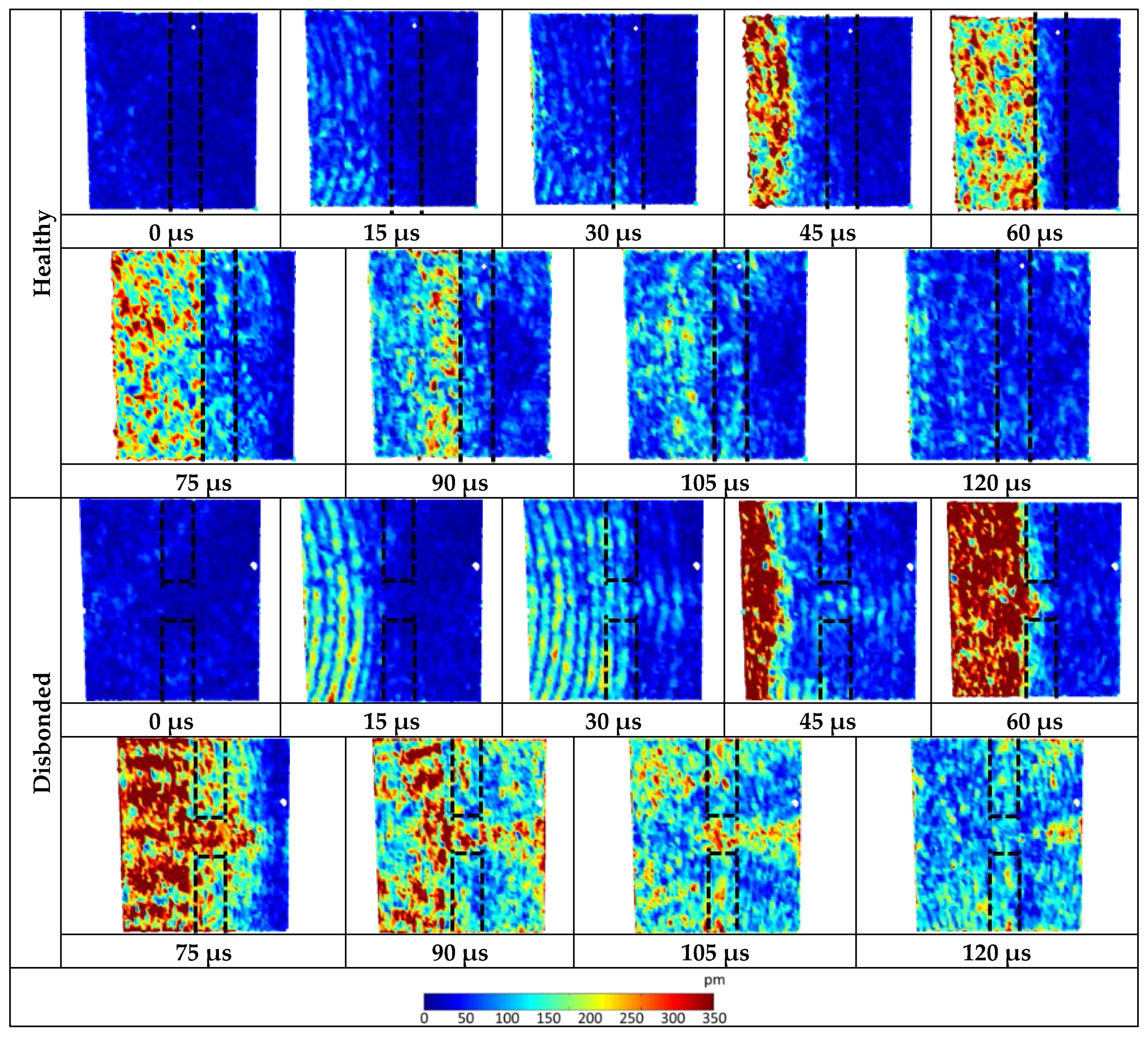
The velocity measurements were integrated using Polytec PSV software to obtain the displacement values. This was carried out to be representative of the signal that a sensor bonded to the structure would measure. The magnitude of each of the displacement components for each excitation frequency are presented in turn. For each set of a results a 0 μs datum point was taken immediately before the S0 mode reached the measurement field. In each plot presented the presence of the stiffener is denoted by the dotted lines.
5.1. 100 kHz Results
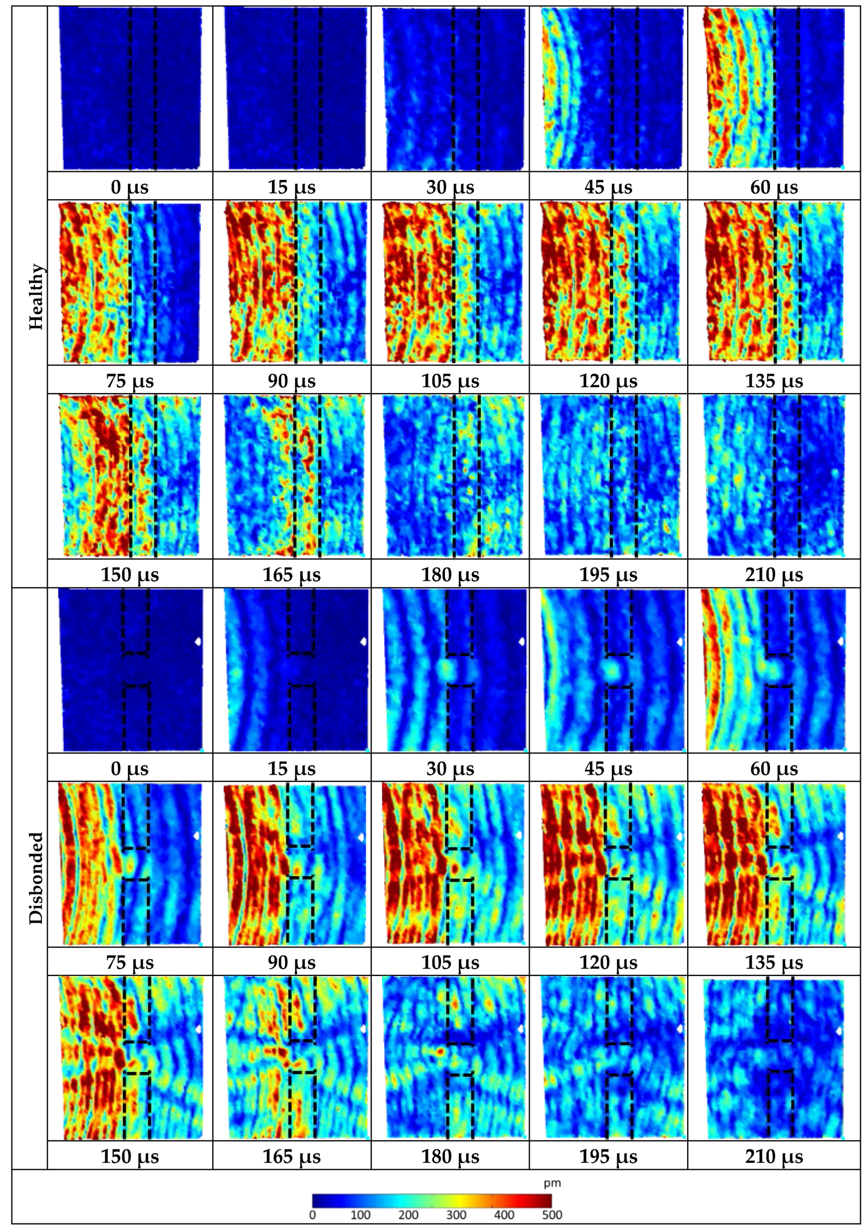
The results from the healthy panel and the panel with the disbonded region are shown in
Figure 4. The results from the healthy panel show that the higher wave velocity S
0 Lamb mode is relatively unaffected by the presence of the stiffener and is mostly transmitted straight through. The slower wave velocity A
0 mode however is greatly affected. At 105 μs in
Figure 4 the A
0 mode interacts with the stiffener resulting in a reduction in amplitude on the other side demonstrating that the majority of the wave energy is being either attenuated or reflected by the stiffeners rather than transmitted.
Figure 4.
100 kHz three-component displacement magnitude showing Lamb wave interaction with the healthy and disbonded stiffened panel.
Figure 4.
100 kHz three-component displacement magnitude showing Lamb wave interaction with the healthy and disbonded stiffened panel.
The results from the panel with the disbond show that in this case the S
0 Lamb mode interacts with the disbonded region of the stiffener. This is seen in
Figure 4 at 30 μs as an area of higher amplitude in the disbonded region. Similarly, a higher level of wave amplitude is observed as the A
0 mode also interacts with the disbonded region shown at 75 μs. As the A
0 mode continues to interact with the disbonded region, transmitted (right of the stiffener) and reflected (left of the stiffener) conical diffraction fringes are observed, clearly seen from 105 μs onwards. The behaviour of the Lamb wave outside of the disbonded region is similar to that of the healthy panel.
5.2. 100 kHz Windowed Cross-Correlation Analysis
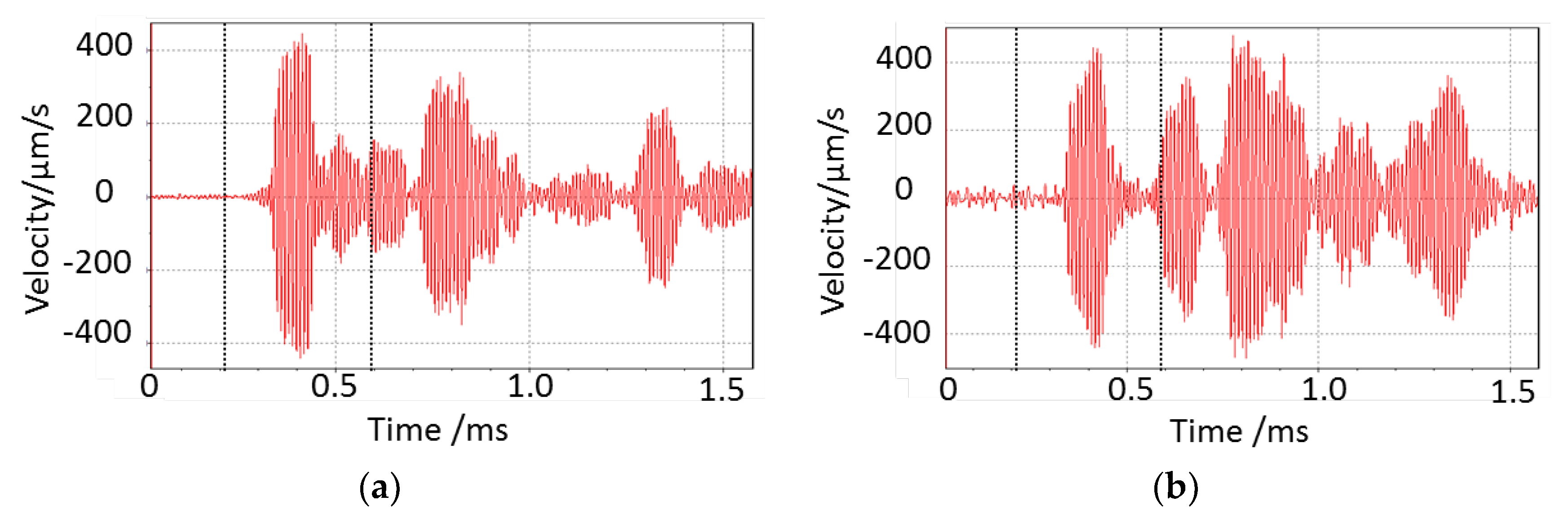
Example waveforms of the out-of-plane component from the corresponding measurement points in the area of investigation are plotted in
Figure 5 for the healthy and disbonded panel respectively. The measurements presented were at the left hand boundary on the centreline denoted by point A in
Figure 2. This measurement point lay equidistant between the excitation site and the stiffener.
Figure 5.
Waveforms from the left hand boundary of the area of investigation in-line with the disbonded region for each panel—(a) Healthy (b) Disbonded. The dashed lines denote the section of waveforms that was used for time windowing.
Figure 5.
Waveforms from the left hand boundary of the area of investigation in-line with the disbonded region for each panel—(a) Healthy (b) Disbonded. The dashed lines denote the section of waveforms that was used for time windowing.
From visual comparison, it is evident that there is a significant difference between the two waveforms. The signal measured from the disbonded panel had a higher level of noise than the signal measured from the healthy panel. This is mostly likely due to a difference in the level of backscattered light received. Even by simple visual comparison, the incoming wave is similar. However, by 0.45 ms there is a significant change in the waveforms. The healthy panel shows the reflected wave-packet from the stiffener whereas this is not present in the waveform from the disbonded panel as the wave is transmitted through the disbond.
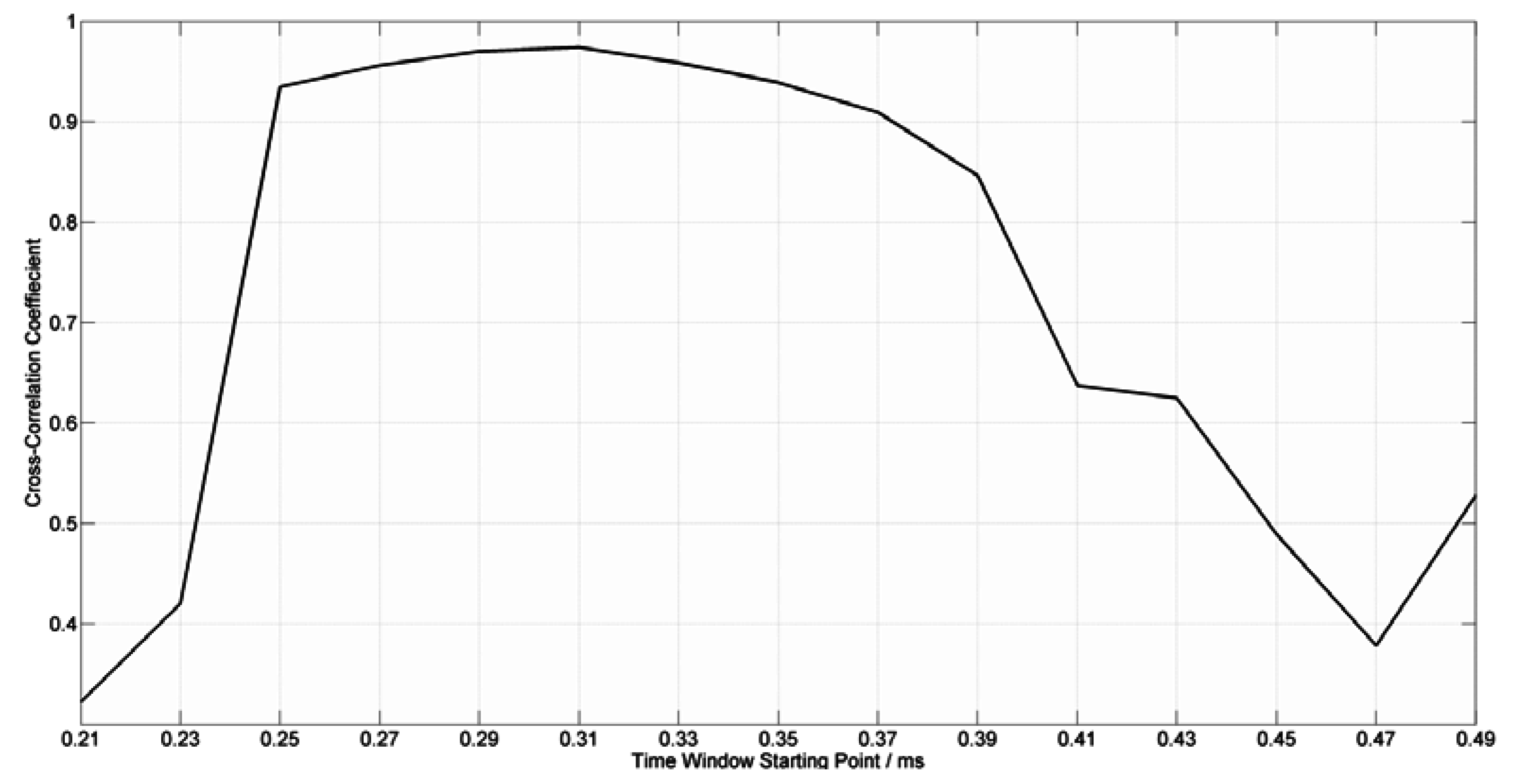
To quantify this difference in the measured waves, a windowed cross-correlation analysis was conducted. Starting at 0.21 ms, both waveforms were windowed into respective 100 μs time windows and the cross-correlation coefficient was calculated. The windows were transposed by 20 μs forward and the cross-correlation coefficient was once again calculated. The cross-correlation coefficients from this analysis are plotted in
Figure 6.
Figure 6.
Moving window cross-correlation coefficient plot.
Figure 6.
Moving window cross-correlation coefficient plot.
The first two time windows show a low value for the cross-correlation coefficient. This is due to random noise mostly being present in these windows. As the wave arrives in the 0.25–0.35 ms time window, the value of the cross-correlation coefficient significantly increases to 0.93 and continues to increase until it peaks in the 0.31–0.41 ms time window at 0.97. It is worth noting that in an installed acousto-ultrasonic system, the cross-correlation coefficient may be higher than this. However, due to two similar panels being used in this experiment and small differences in experimental setup this indicates a good correlation of the two wave forms.
As the waveforms start to differ due to the reflections, the cross-correlation coefficient starts to reduce significantly. In the 0.47–0.57 ms time window the cross-correlation coefficient was found to be 0.38 indicating a large difference in the waveforms and hence, the presence of the disbonded region.
This analysis demonstrates that wave transmitted from the excitation site was comparable on both panels during this experiment. For an installed SHM system this technique demonstrates that reflected waves from the stiffener can be used to identify the presence of disbonds.
5.3. 250 kHz Results
The results from the healthy panel and the panel with the disbonded region are shown in
Figure 7. As with the 100 kHz results, there is a significant reduction in wave amplitude as the A
0 mode interacts with stiffener. The presence of the stiffener is clearly seen in
Figure 7 at 60 μs. As with the results from the 100 kHz excitation, the S
0 mode interacts with the disbonded region illustrated at 30 μs in
Figure 7 by the increase in wave amplitude. The S
0 mode wave energy transmitted through the disbonded region is also shown by a fringe of increased amplitude to the right of the disbonded region.
Figure 7.
250 kHz three-component displacement magnitude showing Lamb wave interaction with the healthy disbonded stiffened panel.
Figure 7.
250 kHz three-component displacement magnitude showing Lamb wave interaction with the healthy disbonded stiffened panel.
The A0 mode is transmitted through the disbonded region with a lower reduction in amplitude than the bonded regions of the stiffener. This has led to a fringe of high amplitude to the right of the stiffener.
5.4. 300 kHz Results
The results from the healthy panel and the panel with the disbonded region when excited at 300 kHz are shown in
Figure 8. As with the other two excitation frequencies, the presence of the stiffener significantly reduces the amplitude of the A
0 mode as it interacts with it as shown at 60 μs in
Figure 8.
Again, as with the other two excitation frequencies, the S
0 wave transmits through the disbonded region more effectively than through the regions that are adhesively bonded as shown at 30 μs in
Figure 8.
At 60 μs the A0 mode also interacts with the disbonded region. This interaction results in a transmitted conical fringe pattern to the right hand side of the stiffener as the wave energy transmits through the disbonded region.
Figure 8.
300 kHz three-component displacement magnitude showing Lamb wave interaction with the healthy and disbonded stiffened panel.
Figure 8.
300 kHz three-component displacement magnitude showing Lamb wave interaction with the healthy and disbonded stiffened panel.
5.5. Comparative Discussion
Lamb waves exhibit a phenomena known as dispersion where the speed of the wave varies with the excitation frequency. When comparing these results, particularly the 100 kHz and 250 kHz results, the higher frequency waves can be seen to travel further in a shorter space of time.
It is due to the dispersion phenomena that the amplitude of the Lamb wave is seen to reduce as it moves across the area of investigation in the higher frequency excitations; therefore demonstrating that the higher frequencies attenuate more.
Comparing the results from the two different panels, the S0 mode is seen to have a greater amplitude in the disbonded panel results. This increase in wave amplitude can be attributed to a difference in sensor coupling. Despite using the same method to couple the sensor to each panel, it is very difficult to achieve a consistent and repeatable sensor coupling.
One significant difference between the three frequencies is the transmitted conical fringe patterns produced by the Lamb wave interaction with the disbonded region. The results from the 100 kHz excitation show a reduction in wave amplitude to the right of the disbonded region. This differs greatly to what is observed in the results from the 250 kHz and 300 kHz excitations where an increased amplitude is seen to the right of the disbonded region. It has been suggested that this may be a function of the difference in the resultant wavelengths of the different excitation frequencies [
38]. This is due to the shorter wavelengths of the higher frequencies being more sensitive to interacting with damage. In terms of the design of a damage detection system however there is a trade-off between the minimum damage size detectable and the global coverage required due to the higher attenuation of the higher frequency Lamb waves.
It may also be noted that the shape of the reflected conical fringe pattern to the left of the stiffener in the 100 kHz excitation results appears to diffract from the entire width of the disbonded region whereas in the other two sets of results the fringe pattern appears to diffract from a much smaller area. It is worth noting that this problem cannot be simply modelled in a similar manner to that of a fluid mechanics problem due to the transmission of the wave through the stiffener and the added complexity of differing wave modes.
The quality of the results from the 250 kHz and 300 kHz excitations are not as clear as the results from the 100 kHz excitation. This could be attributed to the spatial resolution of the scan points. The number of scan points was kept consistent throughout the study in order obtain results that were comparable and to allow the study to be completed in a timely fashion. By increasing the number of scan points more detailed 3D vibrometry fringe plots could be achieved allowing a better comparison to be made between the experimental results.
6. Windowed RMS Analysis
An understanding of the effects of wave interaction is fundamental for use in designing sensor networks to monitor stiffener disbonds on aerospace structures. It therefore is advantageous to obtain an understanding of the amplitude of Lamb wave modes as they interact with defects.
It has been demonstrated by Lee and Staszewski that windowing the time signal and calculating a quantitative measure of the wave amplitude can provide a useful insight for sensor positioning [
39]. This is particularly important for developing SHM systems with a high probability of detection.
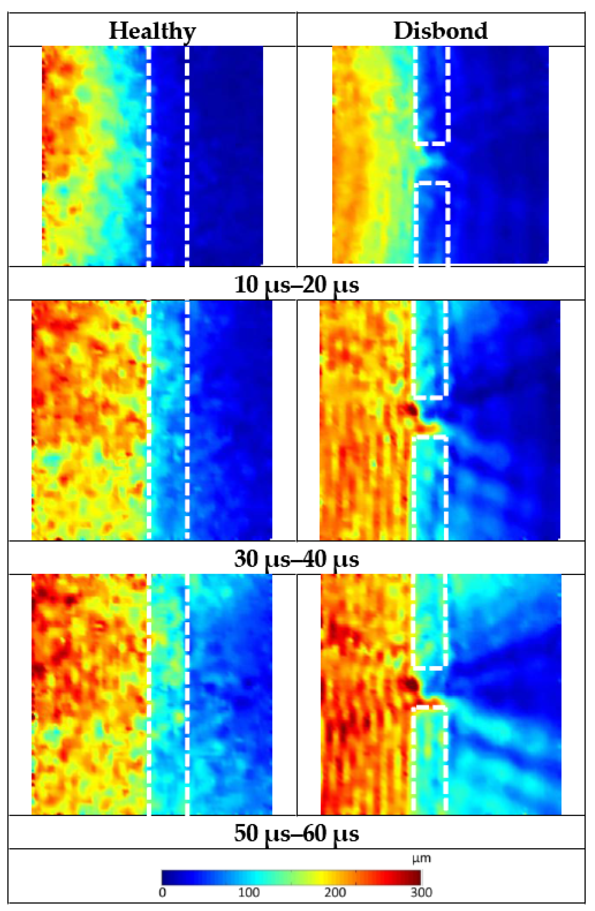
A root mean-squared (RMS) value for a 10 μs time window of the magnitude of the three displacement signals was calculated for each measurement point. For each data set three plots of the time windows have been produced which show three stages of interaction: the S0 mode interacting prior to the A0 mode interacting with the stiffener, the first interaction of the A0 mode and the subsequent transmission and reflection of the A0 mode. Due to dispersion, the higher frequency Lamb waves have higher wave velocities meaning that they interact with the stiffener earlier. Therefore, for each frequency, the three stages of Lamb wave interaction occur at different times, dependant on the wave velocity. Ten microsecond time windows between each plot have not been plotted for simplicity.
6.1. 100 kHz RMS Plots and Discussion
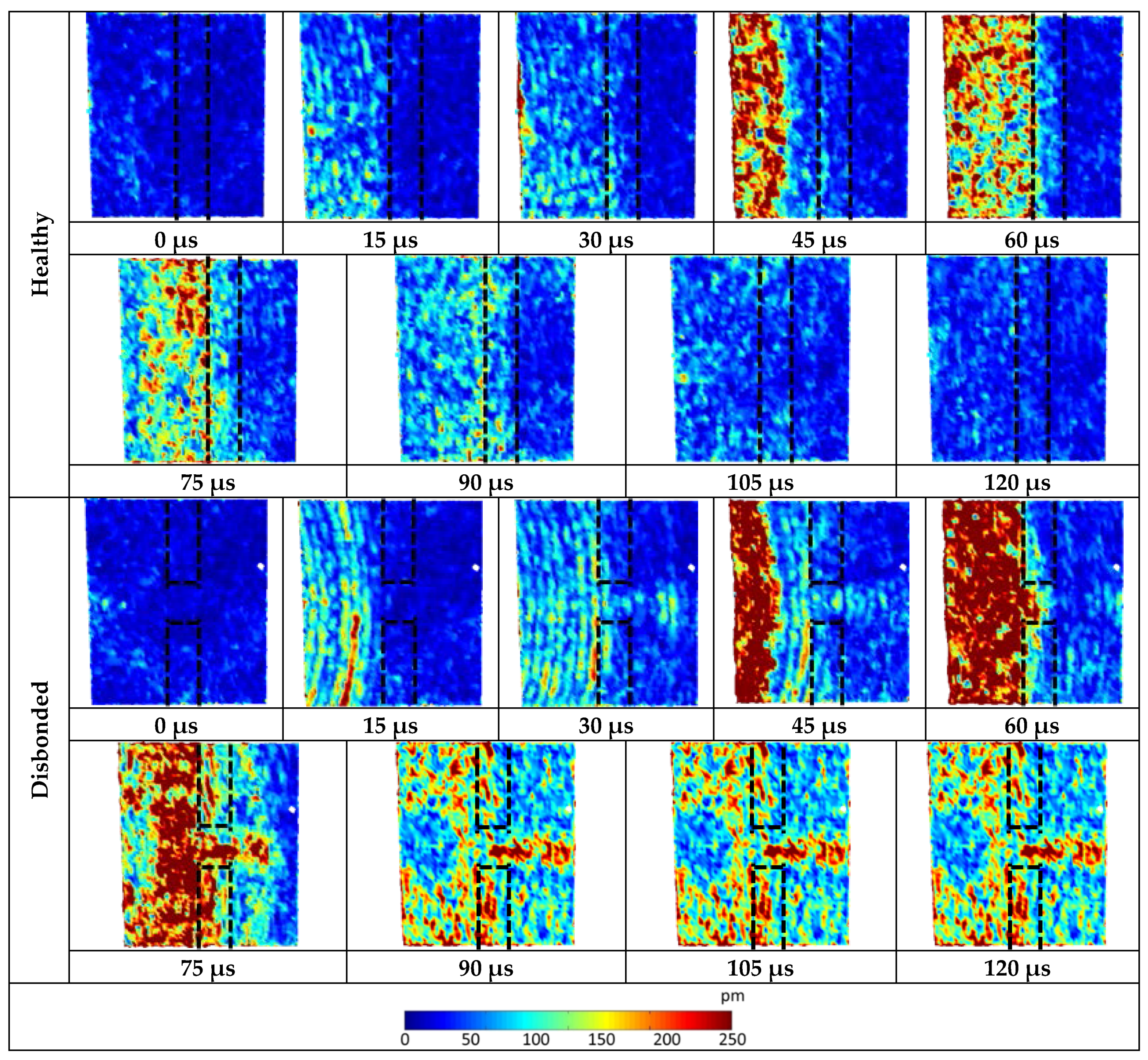
The RMS plots for the healthy and disbonded panels with a 100 kHz excitation are presented in
Figure 9. The time window of 10 μs–20 μs shows the wave packet starting to interact with the stiffeners. In this time window, the only mode present is the S
0 mode. The healthy panel shows clearly the presence of the stiffener as very little energy is transmitted through the stiffener. The panel with the disbonded region however shows an indication of a defect but not as clear or definitive as the later time windows. There is evidence of wave energy “bleeding” into the disbonded region which is initiating a low energy transmitted conical pattern. This is most likely a result of the S
0 mode interacting with the defect.
As the wave continues to interact with the stiffener it is apparent from both the healthy panel and the panel with the disbonded region that some of the energy is reflected back from the stiffener towards the source. This is shown in
Figure 9 by the “tiger-stripe” interference fringes on the left of the stiffener. In the results from the panel with the disbonded region, this interference pattern is disrupted. This is clearly shown in the 50 μs–60 μs window by the circular shape of the reflection pattern to the left of the disbonded region. This reflected conical pattern to the left of the disbonded region has higher RMS values than the neighbouring reflected signal and the reflected signal on the healthy panel. Conversely, as with the plots presented in
Figure 4 there is an area of low energy to the right of the disbonded region. This area of low energy is shown by a transmitted conical region of low RMS values as the A
0 mode interacts with the stiffener. This transmitted conical fringe pattern suggest that at this excitation frequency, a greater amount of the Lamb wave energy is reflected back towards the source than is transmitted through the disbonded region. The shape of the defect is also more prominent as the shorter wavelength of the A
0 mode interacts.
Figure 9.
Windowed root mean-squared (RMS) plots of the three-component displacement magnitude for 100 kHz excitation.
Figure 9.
Windowed root mean-squared (RMS) plots of the three-component displacement magnitude for 100 kHz excitation.
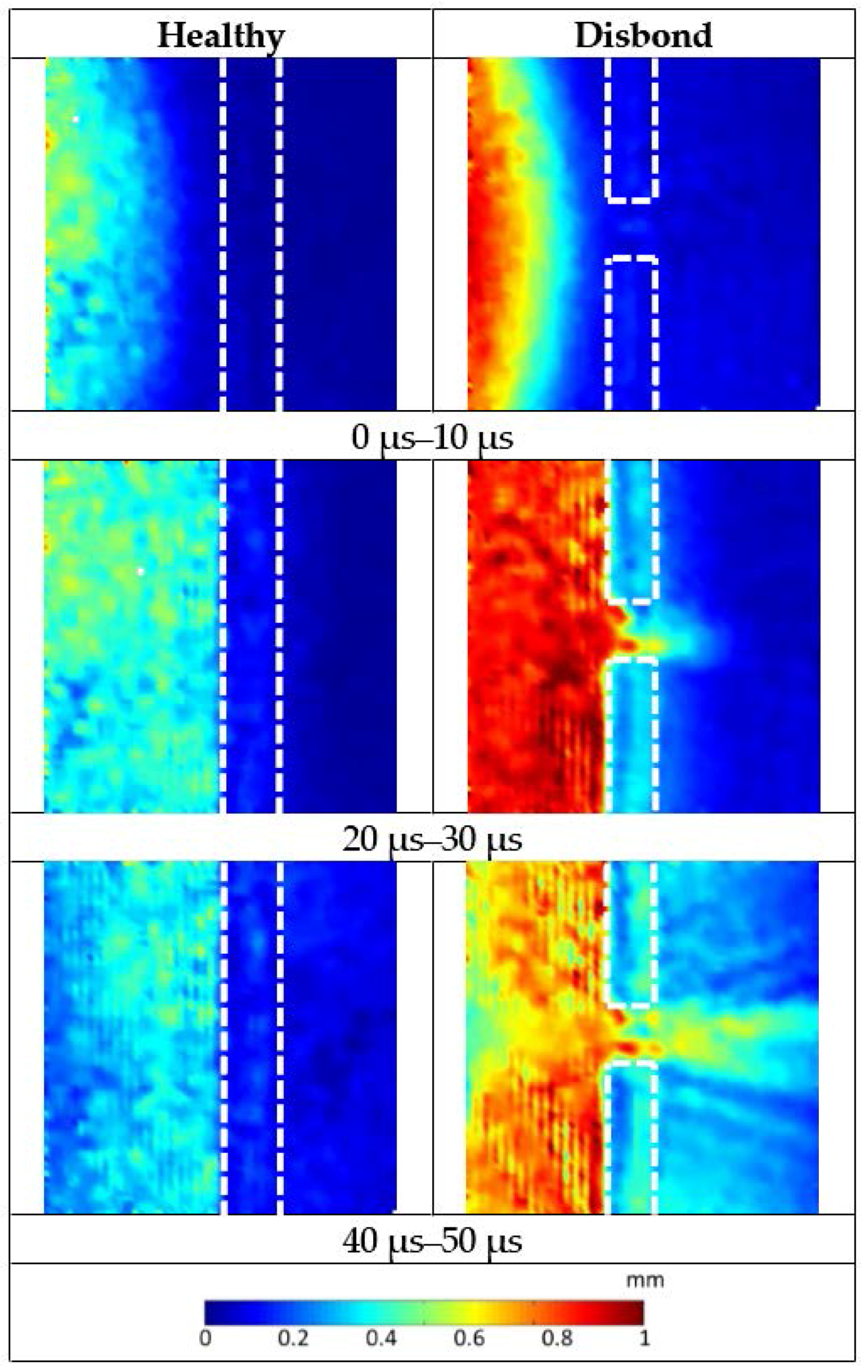
6.2. 250 kHz RMS Plots and Discussion
The RMS plots for the healthy and disbonded panel with a 250 kHz excitation are presented in
Figure 10. The 0–10 μs time window shows an indication that the lower amplitude S
0 mode interacts with the disbonded region. This is shown as two areas of higher RMS above and below the disbonded region.
As with the 100 kHz excitation, as time continues the presence of the stiffener in the healthy panel reduces Lamb wave transmission. This demonstrates that significantly more wave energy is reflected back towards the source and attenuated by the stiffener than is transmitted through it. The 20–30 μs window clearly shows the presence of the disbonded region as the short wavelength of the A0 mode interacts however, the high RMS values observed in the disbonded region do not coincide with the supposed shape of the disbonded region. Instead only a small percentage of the 25.4 mm length of the disbonded region has a high RMS across the whole width of the stiffener. This is seen in the 40–50 μs window to be the source of the transmitted conical fringe pattern. In this window a transmitted conical fringe pattern of higher Lamb wave energy is seen to be “leaking” through this part of the disbonded region. As a result of this there is a significant decrease in RMS values to the left of the disbonded region demonstrating that at this part of the stiffener more wave energy is being transmitted through the stiffener.
The difference in amplitudes of the two datasets, as with results presented in the time domain, can be attributed to a difference in sensor coupling. Despite of this, the results can still be compared qualitatively.
Figure 10.
Windowed RMS plots of the three-component displacement magnitude for 250 kHz excitation.
Figure 10.
Windowed RMS plots of the three-component displacement magnitude for 250 kHz excitation.
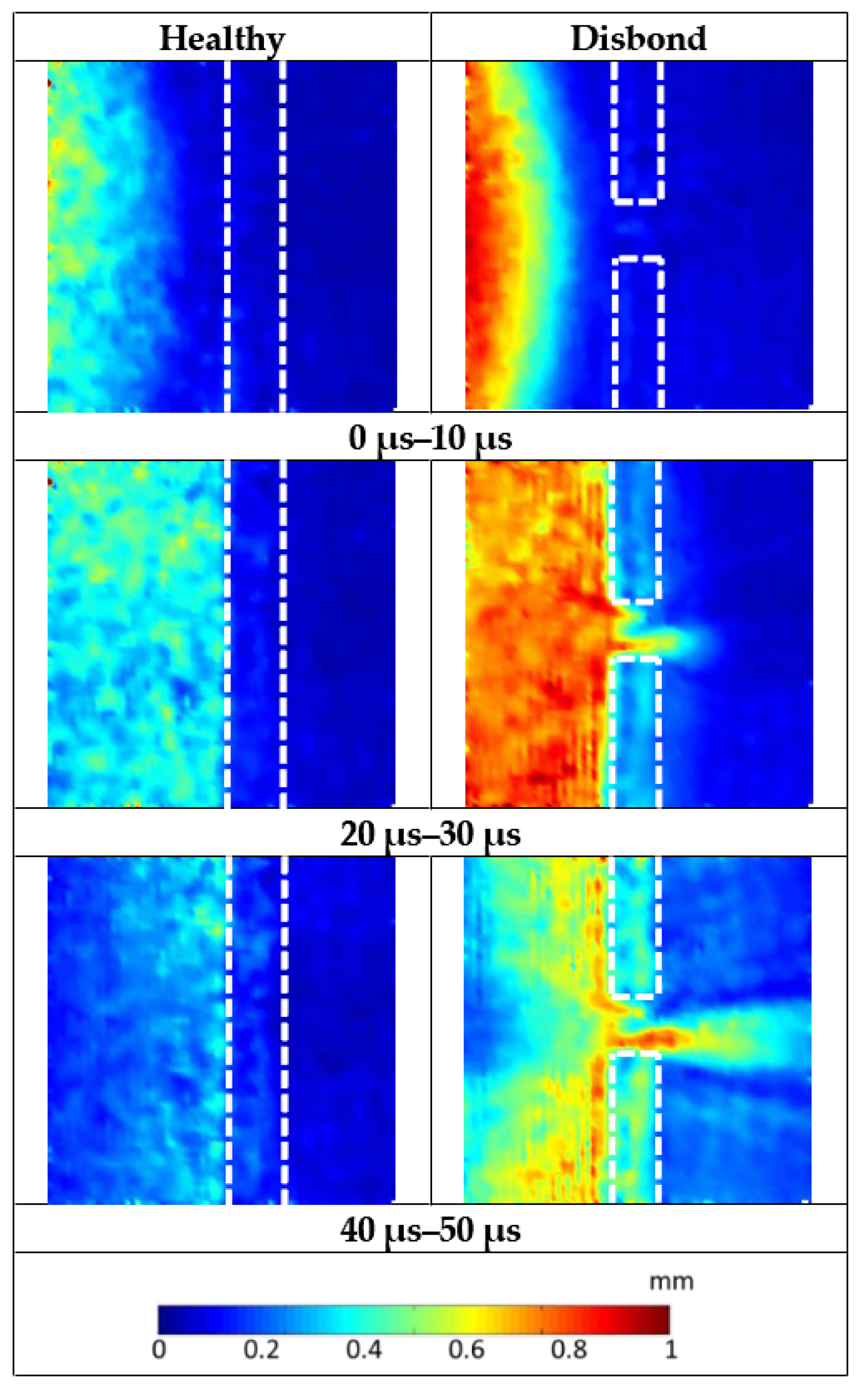
6.3. 300 kHz RMS Plots and Discussion
The RMS plots for the healthy and disbonded panel with a 300 kHz excitation are presented in
Figure 11. As with the 250 kHz a small amount of S
0 Lamb wave energy is seen to be interacting with the disbonded region in the 0 μs–10 μs window. This is shown by a small disruption in the low level RMS values in the disbonded region which are not present in the healthy plot. By adjusting the colour scales it may be possible to improve the clarity of this low energy interaction. However, this low level energy lies in the noise floor of the signal and thus the clarity of the rest of the image may be compromised.
As time progresses again the influence of the stiffener on the Lamb wave transmission is apparent. In the 20–30 μs time window, a clear division of energy is again observed as the A0 mode interacts. The plot of the disbonded panel of the RMS values in this time window again shows the Lamb wave clearly interacting with the induced defect in the disbonded region. As with the 250 kHz excitation, the indication does not appear to be as expected as the values of high RMS are not formed in a square. There is again a line of high RMS values which appear to transmit across the entire width of the stiffener to the bottom of the disbonded region. There is also a smaller region of the high RMS values at the top of the disbonded region.
Studying the 40 μs–50 μs time window, the transmitted conical fringe pattern appears to initiate from the line of high RMS values. This is similar to what was observed with the 250 kHz excitation. A secondary fringe also appears to initiate from the top of the disbonded region. This is can be observed when studying the front of the conical fringes where there are two distinct cones of high RMS values.
As with the 250 kHz excitation, there is a reflected conical fringe of low RMS values to the left of the disbonded region. This indicates that again more Lamb wave energy is being transmitted through the stiffener at this point than is being reflected and attenuated.
Figure 11.
Windowed RMS of the three-component displacement magnitude plots for 300 kHz excitation.
Figure 11.
Windowed RMS of the three-component displacement magnitude plots for 300 kHz excitation.
6.4. Comparative Discussion
There are distinct differences in the windowed-RMS results from the three excitation frequencies. The longer wavelength of the 100 kHz excitation interacts differently with the defect when compared to the shorter wavelengths of the 250 kHz and 300 kHz excitations. The primary difference is that the 100 kHz Lamb wave does not transmit through the disbonded region like the higher frequency excitations. This is demonstrated by the low RMS values to the right of the disbonded region and the higher values to the left indicating that the wave is reflected instead of being transmitted through the disbonded region.
All three sets of RMS plots indicate that the defect in the disbonded region is not a perfect square as was intended. Results at all three excitation frequencies suggest that there is a discrepancy in the defect allowing the Lamb wave to transmit better through the lower part of the disbonded region. This is seen in the RMS plots for the 100 kHz excitation however it is clearer on the higher frequency plots which also suggest that there are other inconsistencies present in the disbonded region.
There is a difference in the amplitudes between the 100 kHz vibrometry data and the higher frequencies shown by the differing values of the colour bars. This can be attributed to the higher frequencies attenuating more, thus the Lamb wave energy decreases significantly in the higher frequency plots.
7. Ultrasonic Inspection of Disbonded Region
As discussed, on reviewing the vibrometry results it was noted that the conical diffraction fringes were not as expected. From the displacement results, particularly the higher frequency excitation, the transmitted conical fringe appeared to originate from a smaller area at the bottom of the disbonded region. To investigate the condition of the induced disbonded region an ultrasonic C-scan (Midas NDT Systems Ltd, Ross-on-Wye, UK). was completed. This method uses a water-coupled ultrasonic probe which pulses out an ultrasonic wave through the structure which reflects off a glass plate on the other side of the structure. The amplitude of the reflected signal is recorded as the probe transverses the structure. Differences in received amplitude allow a plot of the inspected area to be produced [
40].
7.1. Experimental Setup
The panel with the induced disbonded was cut down to dimensions of 465 mm × 626 mm to enable it to be positioned in to the C-scan apparatus while ensuring that the cutting operation would not affect the disbonded region.
A MIDAS NDT water coupled C-scan unit was used with Zeus software (Midas NDT Systems Ltd, Ross-on-Wye, UK) to record the results.
7.2. Results and Discussion
The results from the C-scan are plotted in
Figure 12. It is apparent that there was something present in the disbonded region which had had an effect on the interaction of the Lamb wave, shown in
Figure 12 as a light grey area in the disbond region.
It was suspected that this defect occurred during the manufacturing process when the intentional disbond was being created. The disbonded region was induced by using PTFE). When the adhesive was cured the PTFE tape was removed however it was possible that some tape was left inside the bond due to the difficulty of removing it. Therefore it is believed that the conical fringe patterns were caused by the Lamb wave interaction with this PTFE tape.
With that stated, it is highly unlikely that a disbond that occurs on an aircraft during its in-service life or its manufacture would be perfectly square and is more likely to be irregular in shape. Therefore, it is fair to state that the disbonded region that has been produced in this study is potentially more representative of what is likely to be found on a real aircraft structure.
Figure 12.
C-Scan results of the panel with the disbonded region. Note the region with the induced disbond containing what appears to be remnants of PTFE tape.
Figure 12.
C-Scan results of the panel with the disbonded region. Note the region with the induced disbond containing what appears to be remnants of PTFE tape.
The C-scan results also show that there is a small discontinuity in the adhesive film thickness of the healthy region of the stiffener. This is shown by a difference in the amplitude of the frequency response. This highlights the issue of the inconsistency of adhesive bonds.
8. Swept Sine Wave
The RMS results presented in
Figure 7,
Figure 8 and
Figure 9 demonstrated that the excitation frequency of a Lamb wave has a significant influence on interaction with defects due to the difference in wavelength. An additional experiment was undertaken using a swept sine wave excitation to further investigate the Lamb wave interaction.
8.1. Experimental Setup
A conical transducer developed by the National Physical Laboratory was acoustically coupled in line with the disbonded region at a distance of 312.5 mm from the midpoint. This excitation source was chosen for its flat broadband response across a range of frequencies [
41]. The same excitation hardware was used for this investigation as previously. A swept sine wave ranging from 100 kHz to 500 kHz over a 200 μs duration was used for the excitation signal. This time window allowed the entire frequency sweep to be excited while reducing the effect of reflections.
The same vibrometry setup was used for this investigation although the area of investigation was changed to 250 mm × 90 mm with 5805 velocity measurement points. This not only improved the spatial resolution required for the higher frequency waves but also allowed the focus to be solely on the wave interaction with the disbonded region.
A sample of duration of 800 μs was used for this investigation as it allowed the whole transmitted wave to be captured at all measurement points while minimising the recording of edge reflections.
8.2. Results and Discussion
The RMS value of each of the 5805 velocity measurement points was calculated and plotted as shown in
Figure 13. Though measurements were taken for all three planes, the out-of-plane measurements most clearly show the interaction (most likely due to the source primarily exciting out-of-plane modes).
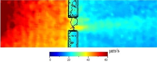
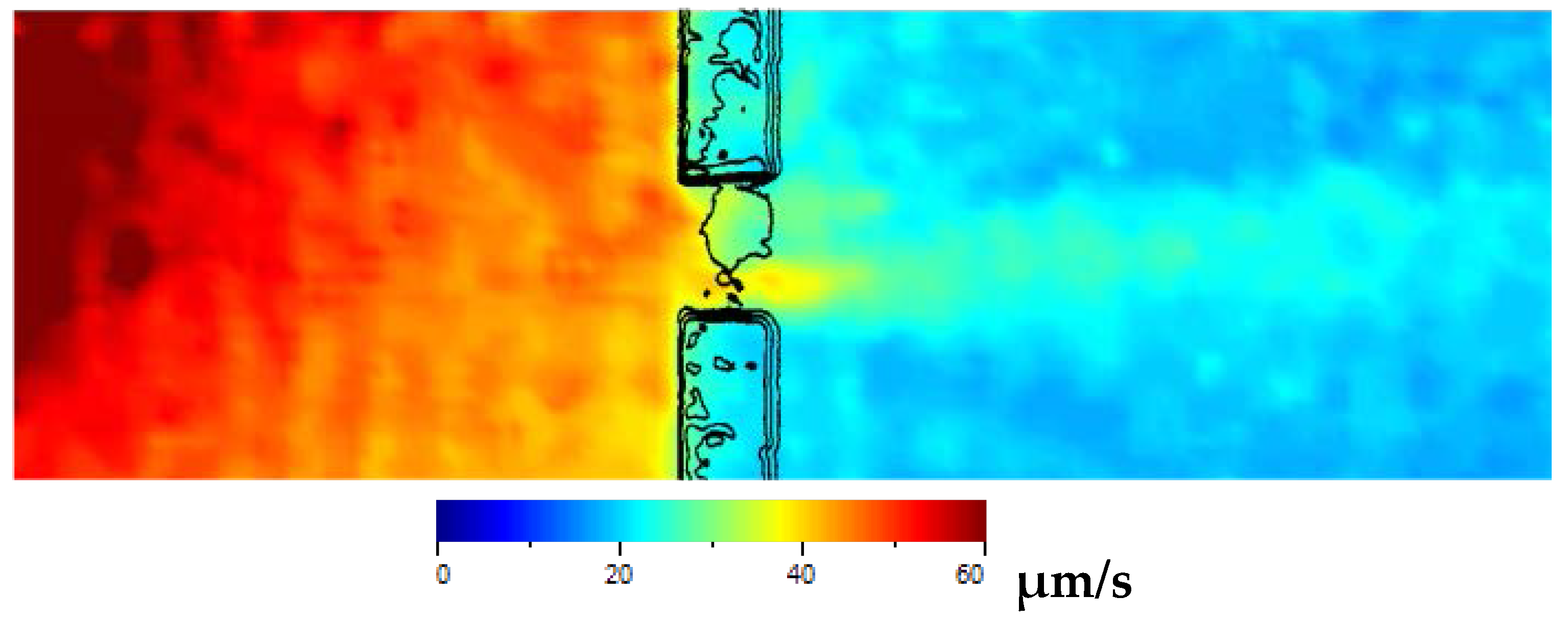
Figure 13.
100–500 kHz swept sine wave excitation out-of-plane RMS plot with an outline of the C-Scan over laid. Note the reduction in wave energy surrounding the PTFE tape region causing a reduction in high amplitude waves transmitting through the disbonded region.
Figure 13.
100–500 kHz swept sine wave excitation out-of-plane RMS plot with an outline of the C-Scan over laid. Note the reduction in wave energy surrounding the PTFE tape region causing a reduction in high amplitude waves transmitting through the disbonded region.
It is apparent that the presence of the stiffener has a significant effect on the amplitude of the Lamb wave. On the left side of the stiffener, RMS amplitudes in excess of 60 μm/s were observed. As the Lamb wave is transmitted through the stiffener the RMS amplitude reduces to less than 15 μm/s; an approximate decrease of 75%.
As observed with the time domain results, a conical transmitted diffraction fringe is present to the right of the disbonded region. This is seen in
Figure 13 as a region of higher amplitude (light blue).
As with the time domain results, particularly at 90 μs in
Figure 8 the transmitted conical fringe pattern originates from the lower part of the disbonded region. This is particularly highlighted in
Figure 13 where in the disbonded region the areas of highest amplitude (yellows) are observed in the lower part of the disbonded region.
When the results from the C-scan are superimposed onto this RMS plot it is evident that the region suspected of being remnants of PTFE tape has a significant influence on the propagation of the wave as the amplitude significantly reduces in this region.
As with the 300 kHz plots in
Figure 11, areas of high RMS values are observed at the top and the bottom of the disbonded region. When comparing this to the results of the C-Scan it is evident that no or very little PTFE tape (or other obstruction) is present across the width of the stiffener in these areas.
9. Discussion
It is apparent that the induced Lamb waves all interacted with the disbonded region of the stiffener. There was a quantifiable difference in the Lamb wave interaction when compared with the results for the healthy panel. This demonstrates that by using a statistical measure of the difference of the received Lamb wave such as the cross-correlation technique [
42] it would be possible to use an acousto-ultrasonic system to routinely inspect the condition of bonded stiffeners. By combining this technique with a statistical measure of the received energy, such as calculating the RMS value as demonstrated in this study, the location and characterisation of the damage could also be potentially assessed.
The results presented also demonstrate that the excitation frequency of an ultrasonic system is an important consideration for inspecting adhesively bonded stiffeners for disbonds. The 100 kHz excitation did not transmit through the disbonded region whereas the higher frequencies did. For damage detection systems, particularly those which are triggered on an amplitude threshold, this is particularly significant to fully ensure a high probability of detection.
This study only considered a bond which had areas where the disbond spanned the whole width of the stiffener. In the case of real aircraft structure, this may not be the case. It would be beneficial to also be able to detect this type of disbond. The results from the 100 kHz excitation suggest that this could be possible by considering the response of the reflected signal. Therefore an acousto-ultrasonic system capable of pulsing and receiving at different frequencies would be beneficial.
All three excitation frequencies used in this study demonstrated that a low amount of the induced Lamb wave energy was transmitted through the stiffener. This is clearly a consideration for acousto-ultrasonic SHM systems but should also be considered important for passive SHM systems such as acoustic emission (AE). AE induced Lamb wave propagation will be affected by the presence of adhesively bonded stiffeners on a structure. AE events occurring on one side of a stiffener may not be detected by sensors on the other side due to the decrease in Lamb wave amplitude. In addition to this, signals reflected from the stiffener may be interpreted incorrectly leading to added complication when locating and characterising damage using passive techniques. Therefore, the geometry of a structure is an important consideration for the design of a passive AE sensor network.
The results from the RMS plots demonstrate that laser vibrometry is not only a powerful tool in increasing understanding of Lamb wave interaction but can also be used to indicate the size and shape of a defect. The RMS plots serve as a useful aid in considering optimal sensor locations for an active sensor network by highlighting areas of high Lamb wave energy.
The transmission of the S0 mode through the disbonded region seems mostly unaffected by the presence of the PTFE tape regardless of excitation frequency. The S0 mode is mostly constructed of in-plane components which gives reason to suggest that in-plane modes maybe less influenced by the presence of kissing bonds. Further investigation using in-plane excitation would be beneficial to further investigate in-plane Lamb wave interaction with stiffeners.
10. Conclusions
This paper has demonstrated how 3D scanning laser vibrometry can be used to conduct a thorough investigation of Lamb wave interaction with adhesively bonded stiffeners and adhesive disbonds. The work presented has demonstrated that the way in which Lamb waves interact with disbonds is dependent on the excitation frequencies.
Analysis performed using a windowed RMS technique has revealed areas of high and low Lamb wave energy. This has revealed that, dependent on excitation frequency, conical fringes with high levels of Lamb wave energy can be found to be either reflected or transmitted through an adhesive disbond.
RMS plots are also beneficial in revealing optimal structural areas for locating sensors to ensure a high probability of damage detection using Lamb waves. These plots demonstrate the complexity of sensor network design and show that considerations such as amplitude threshold are important for use in active sensing systems.
The C-scan inspection revealed the suspected presence of PTFE tape within the disbonded region which had a significant influence on the interaction of the induced Lamb wave. By inducing a frequency swept Lamb wave and plotting the RMS of the velocity measurements taken using the 3D scanning vibrometer it was possible to clearly observe the Lamb wave interaction. This revealed the shape of the PTFE tape which correlated well with the results from the C-scan.
This study has only considered the wave interaction when the actuator is in line with disbond. In reality, this may not be the case. Therefore, it would be beneficial to investigate the effect of the actuator being at different angles and distances relative to the disbond. Other considerations could also be taken into account including defect size in order to work towards achieving an optimisation platform for sensor network design. By using the 3D scanning laser vibrometer as a validation tool, it is possible to validate computational models of a Lamb wave interaction. Therefore it would be of significant benefit to be able to model several damage scenarios which would then allow a platform for sensor location optimisation to be produced.
The work presented has shown that acousto-ultrasonically induced Lamb waves are a suitable method for the in-service monitoring of adhesively bonded structures for SHM applications. Careful consideration must be taken however when planning sensor location due to the complexity of the interaction with adhesive disbonds, in particular disbonds with irregular shapes.


