Linear Electro Optic Effect for High Repetition Rate Carrier Envelope Phase Control of Ultra Short Laser Pulses

Abstract
:
1. Introduction
2. EO CEP Shifter
2.1. Theory
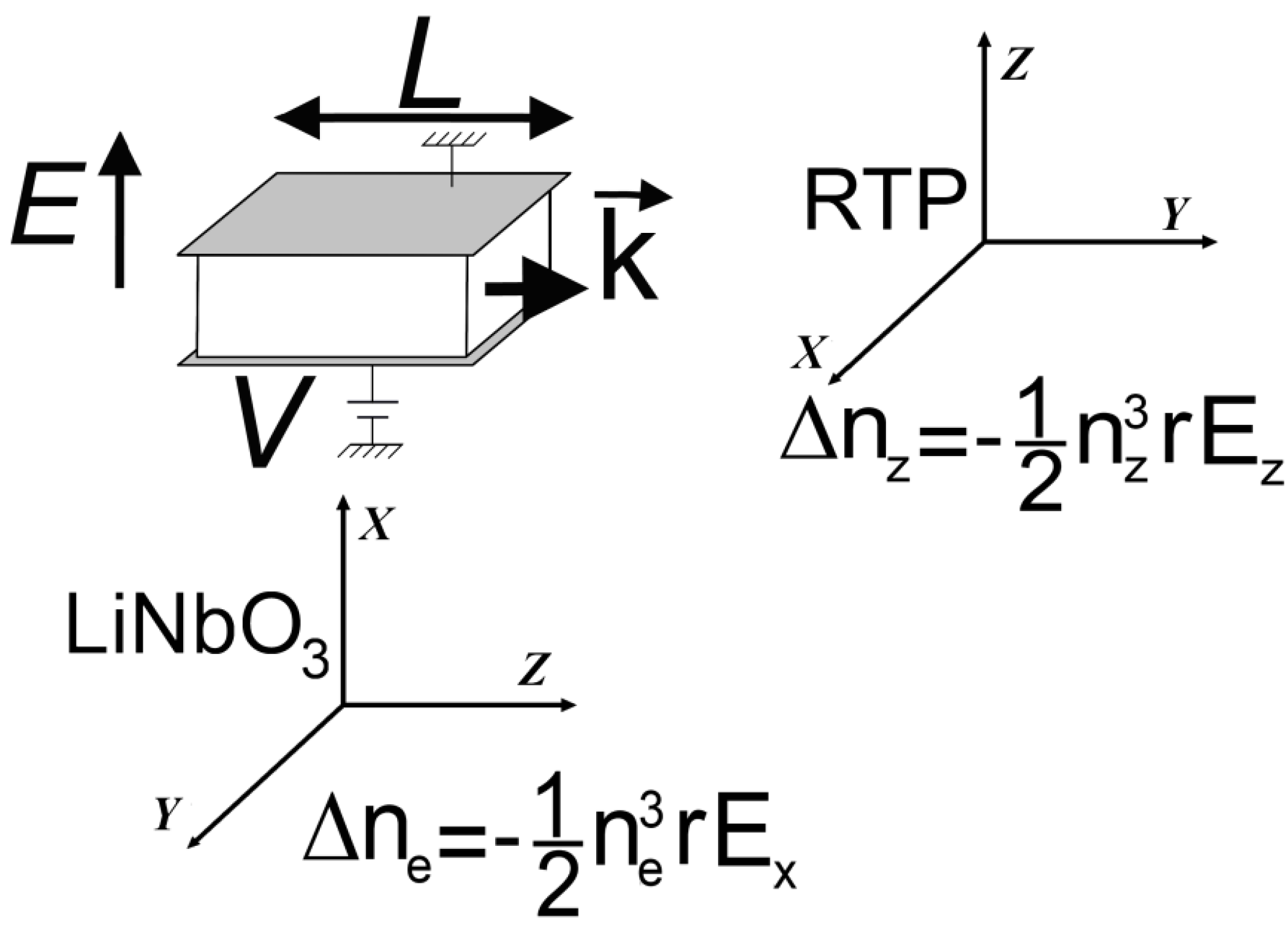
 , after propagation in the EO crystal when applying the electric field is defined by:


 is the refractive index without applied field.
2.2. Experiments
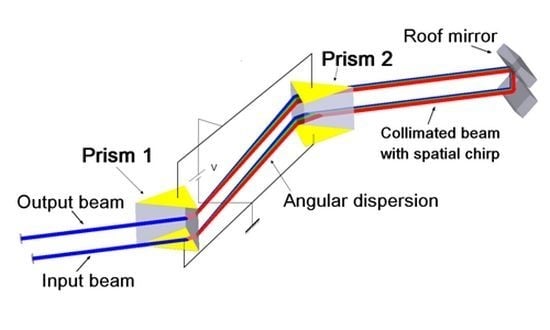
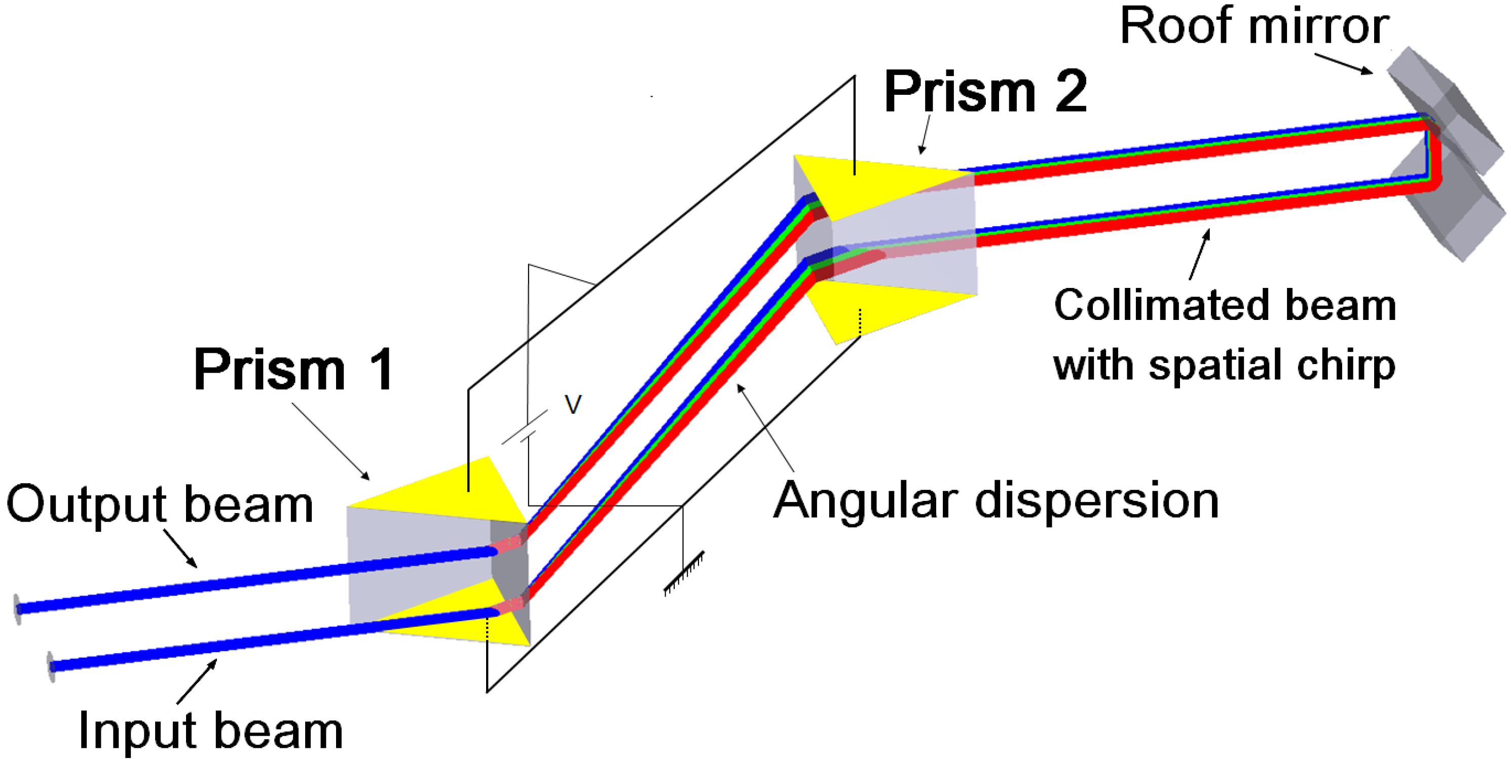
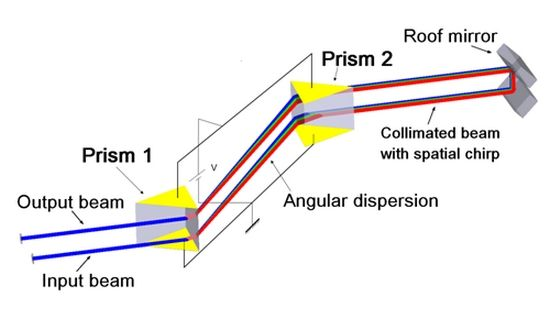
3. Prism Pair CEP Shifter
3.1. Introduction
3.2. Theory

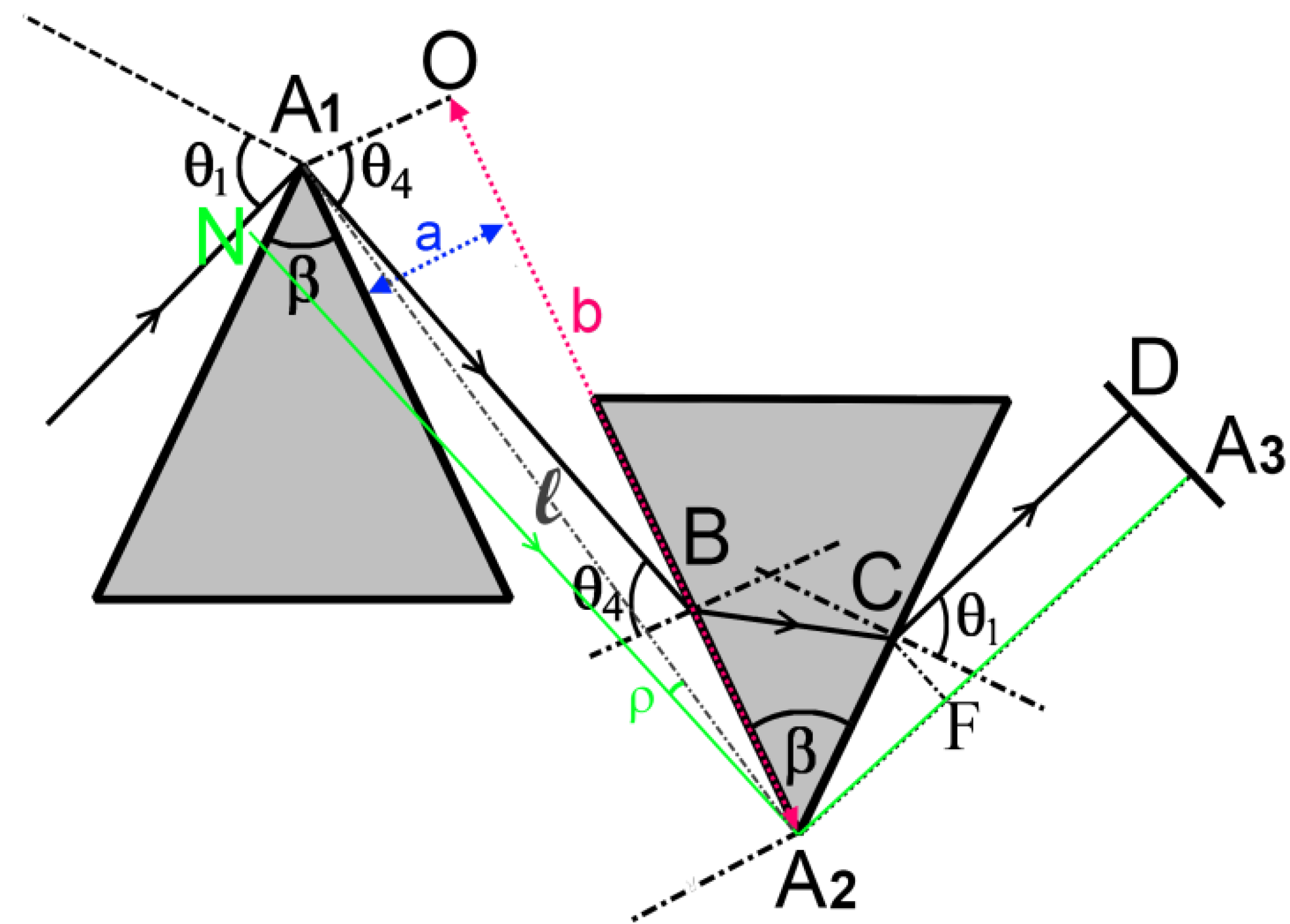
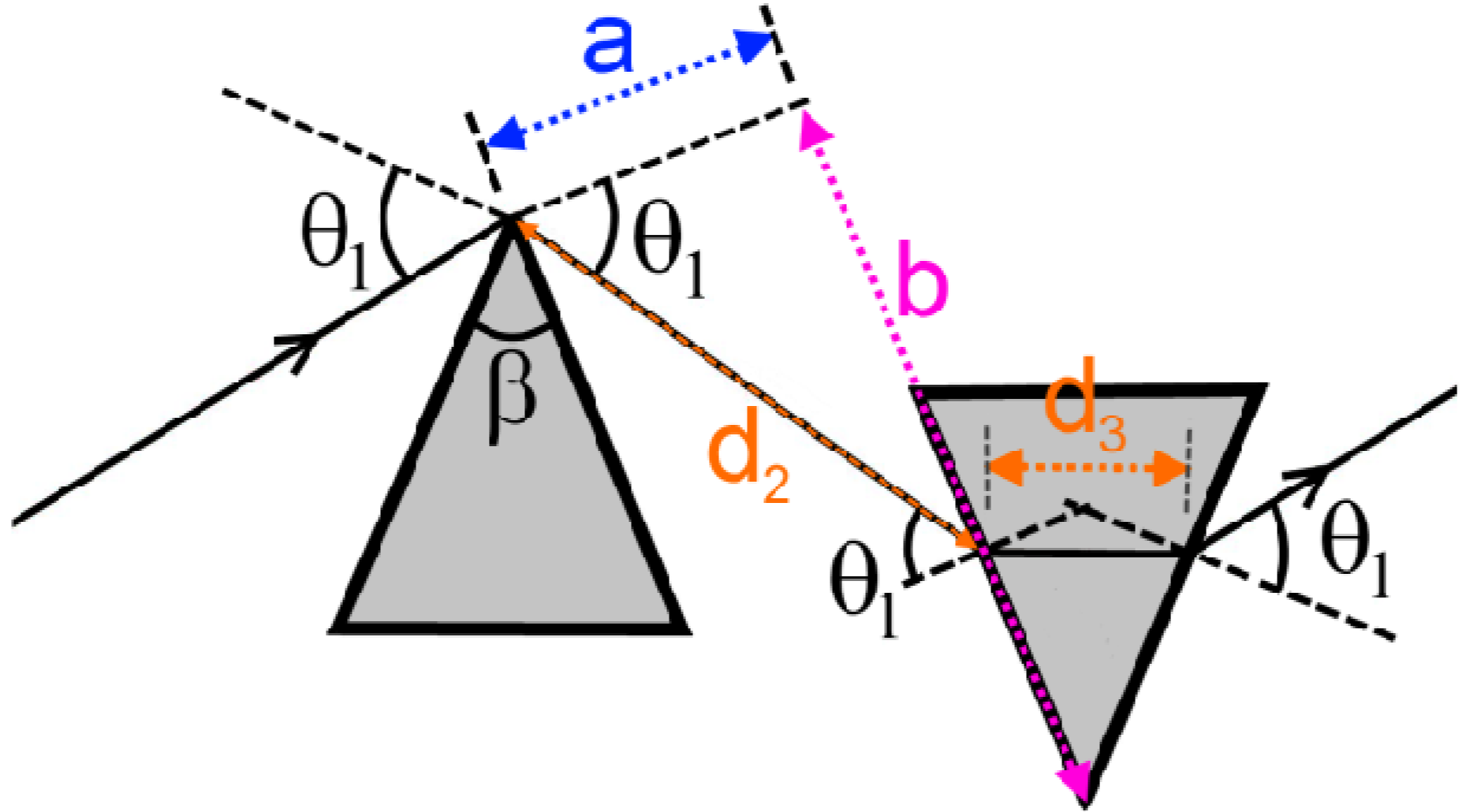
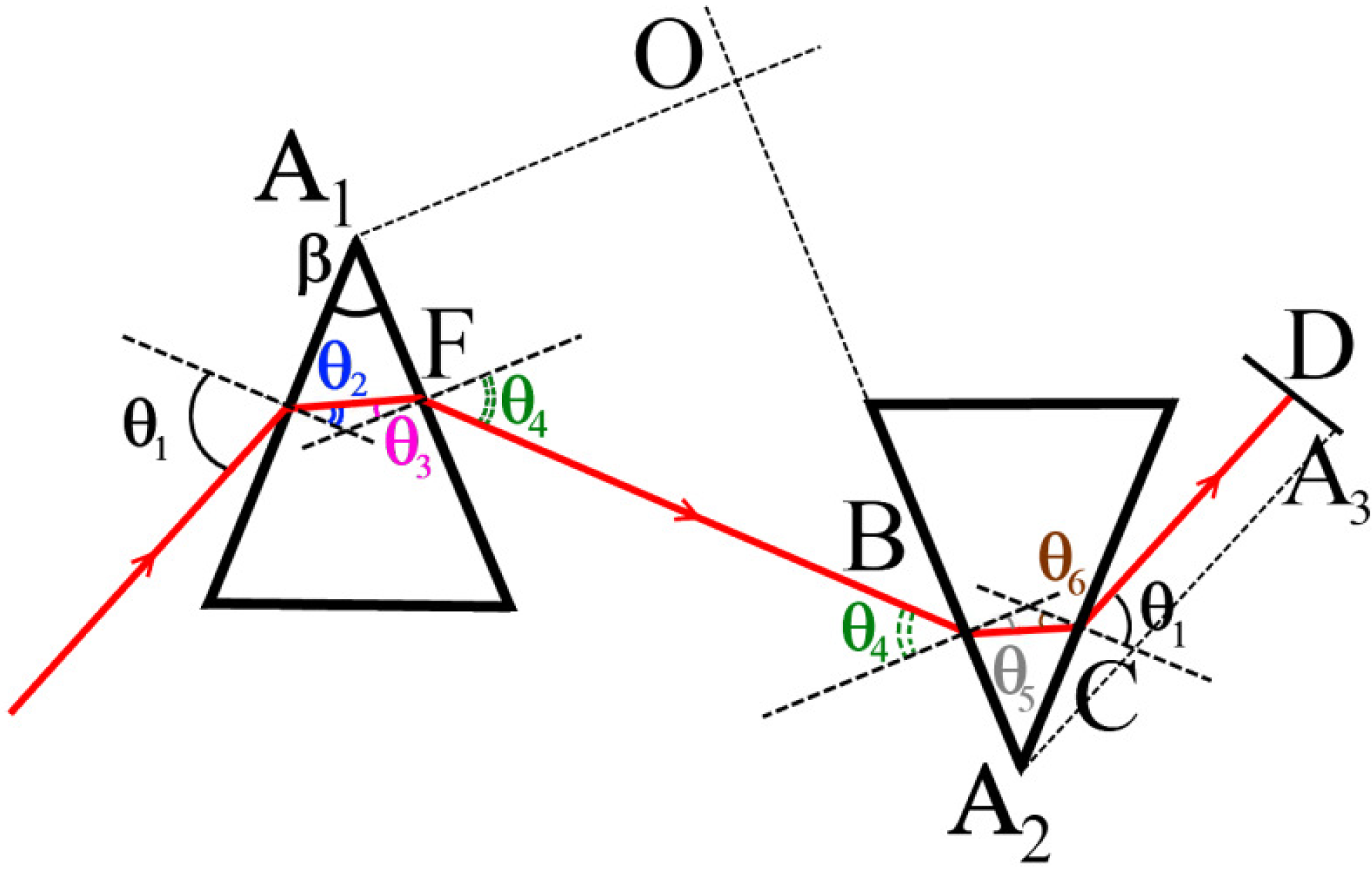
3.2.1. General Configuration


 is the angle, (A1A2O), between A1A2 and A1O, one obtains the following relation:


 , and second order dispersion,
  , have, respectively, the following expression:


3.2.2. Minimal Deviation Configuration


 , and using λ instead of ω. Equation 21 becomes (Appendix IV):


 for isochronous CEP shifter and PGD generator configuration are, respectively, given below:

 . It can be written in our notations as:

 ) at :

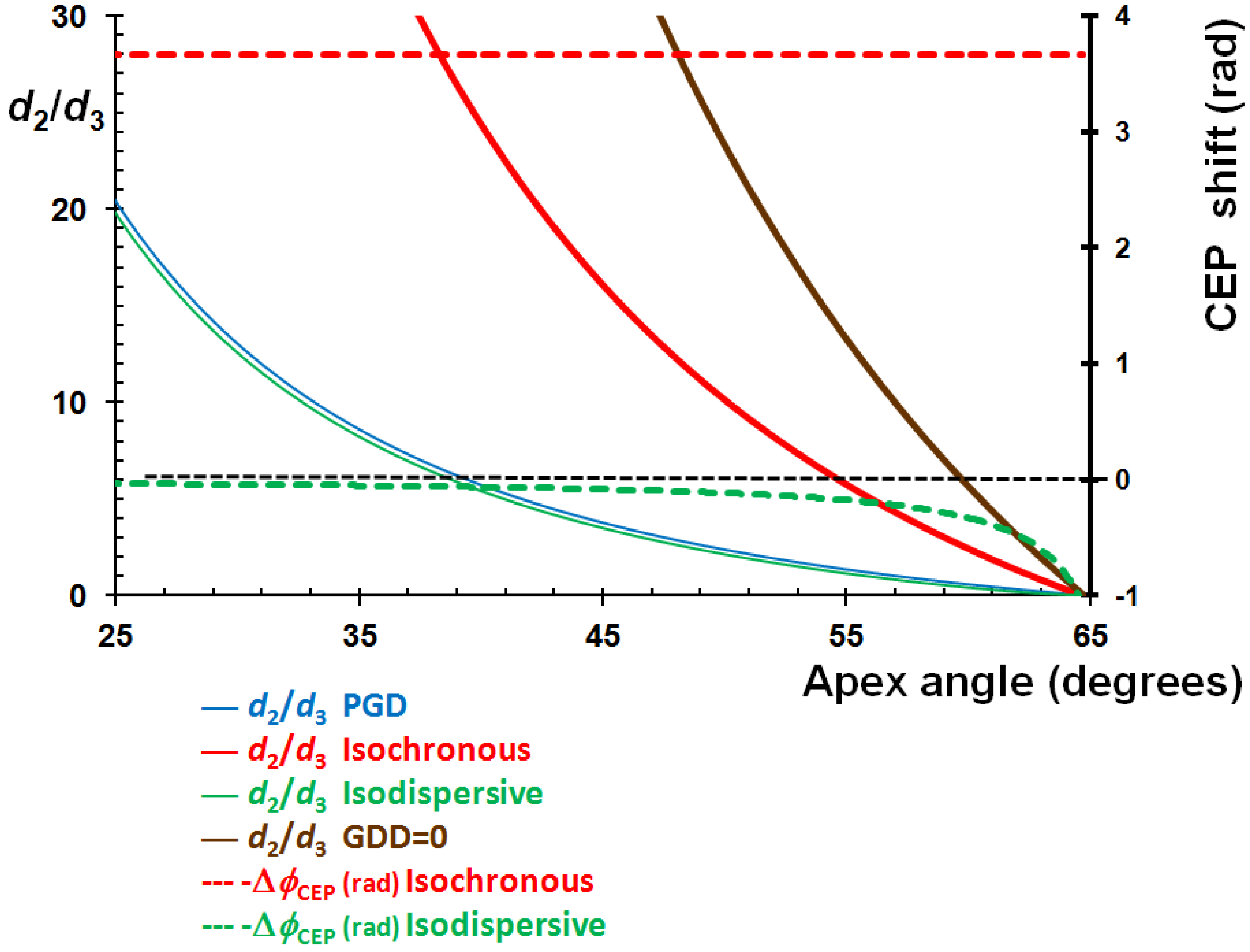
3.3. RTP Prism Pair CEP Shifter
 , thick red), the PGD (
  , thick blue) and the iso-dispersive conditions (
  , thin green) are imposed. This gives a means of comparing the performances of each configuration. The thick brown line corresponds to a zero dispersion condition when no electric field is applied (
  ) to the set-up.
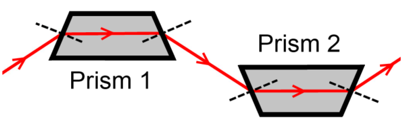

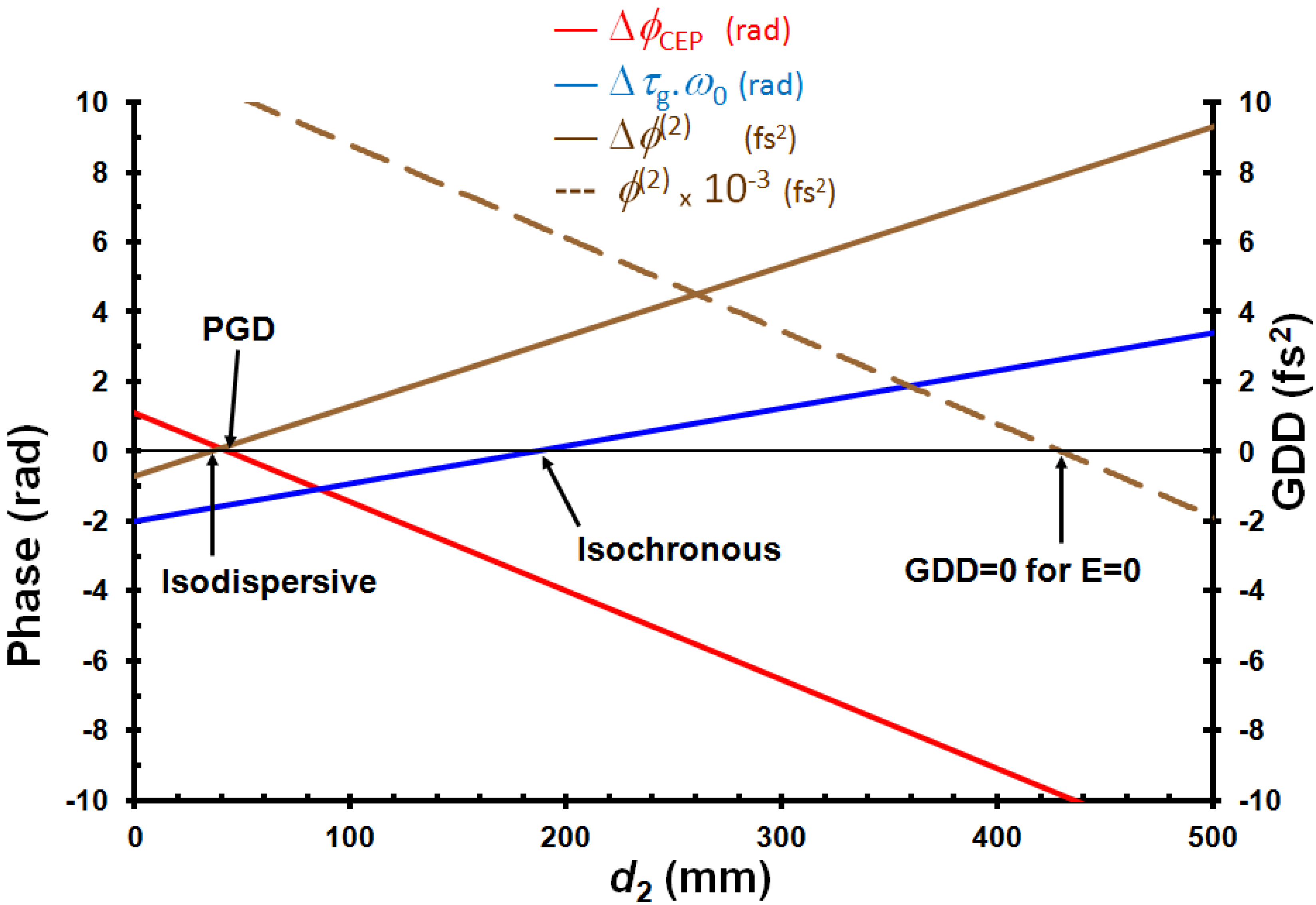
 —blue line) and the induced GDD (brown line) at central frequency, ω0, as a function of d2. The group delay dispersion,
  (GDD) for E = 0 is also plotted (dotted brown line). These results are obtained in the case of an apex angle of the prisms,
  , a total path length, d3 = 40 mm, at
  nm and a static electric field, E = 1 kV/cm.
 and introduced by a RTP prism pair CEP shifter versus d2 for the following parameters (apex angle , d3= 40 mm, E = 1 kV/cm; a value E = 0 kV/cm is assumed for the calculation).
and introduced by a RTP prism pair CEP shifter versus d2 for the following parameters (apex angle , d3= 40 mm, E = 1 kV/cm; a value E = 0 kV/cm is assumed for the calculation).
and introduced by a RTP prism pair CEP shifter versus d2 for the following parameters (apex angle , d3= 40 mm, E = 1 kV/cm; a value E = 0 kV/cm is assumed for the calculation).
3.4. Comparison between Different CEP Shifters

| EO CEP Shifter | Dazzler | Grating compressor | Glass wedges | 4f + LCD | Lens + rotating grating | ||
|---|---|---|---|---|---|---|---|
| Longitudinal single pass | Prism pair double pass | Double pass | |||||
| Δτg (fs) | −5.78 | 0 | 0 | 7.9 | 43.7 | 0 | 0 |
| Δ Ф(2) (fs2) | -2 | 2.6 | 0 | 1.7 | 1 | 0 | 0 |
| E (kV/cm) | 2.86 | −0.43 | - | - | - | - | - |
| Displacement (µm) | - | - | - | 0.54 | - | - | - |
| Bandwidth | MHz | MHz | <30 kHz | ~10–100 Hz | ~1–10 Hz | ~10–100 Hz | ~1 kHz |
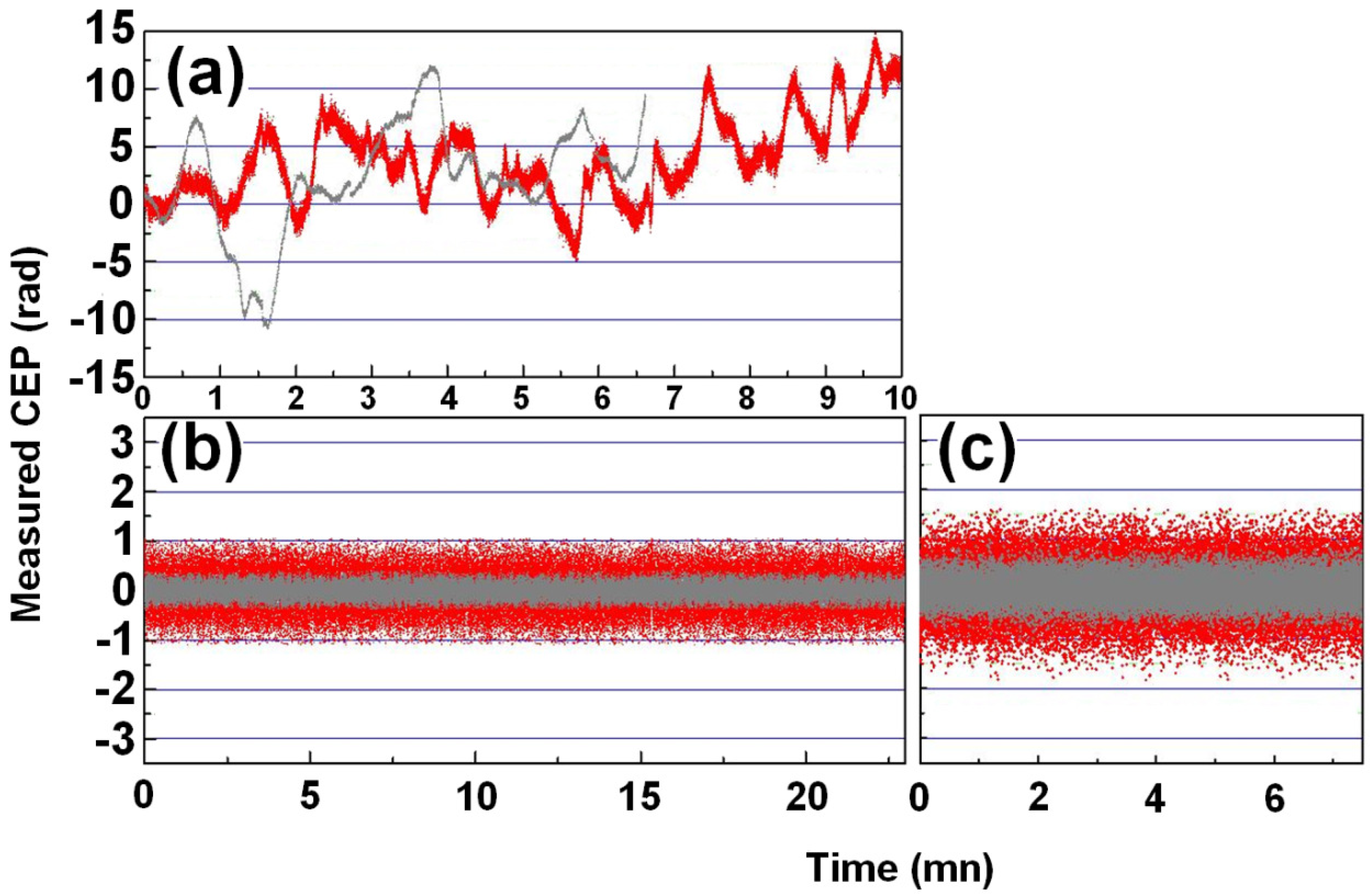
4. Conclusions
 , is verified. This shows that corrections can be made, even on very short pulses, the most important point being the ability of the system to correct the CEP at a very high speed, which can very probably be extended to the 100 kHz range.
 Acknowledgments
Conflict of Interest
Appendix 1: Derivation of the Isochronous Condition (General Case)—Equation 16
- -
- β apex angle of the prisms;
- -
- θ1 incident angle on prism 1;
- -
- θ2 refracted angle in prism 1;
- -
- θ3 incident angle on the output face of prism 1;
- -
- θ4 refracted angle after prism 1 (in air);
- -
- θ5 incident angle on prism 2;
- -
- θ6 refracted angle in prism 2;
- -
- θ7 = θ1 incident angle on output face of prism 2.

 , as a function of geometrical parameters, a,b, and the angle, θ4 (Figure 5). The variation of the group delay, Δτg, when applying the electric field, E, is given by:


1.1.Calculation of A:


 (See Figure 5), the light pass in prism 2 without electric field applied, has the following form:

1.2.Calculation of B:


1.3.Group Delay


 leads to a relation between x30 and a, which does not depend on E. Using Equation A.9 and Equation A.18, one obtains Equation 16.
 Appendix 2: Derivation of the Pure Group Delay Condition (General Case)—Equation (18)


Appendix 3: Derivation of Equation 21


Appendix 4: Derivation of the Equation 22
 . This relation is obtained using Equation 21, which is valid for any frequency. At central frequency, as represented on Figure 6, the following relations take place:

 and using the central wavelength,
  , instead of the central frequency, ω0, one obtains immediately Equation 22.
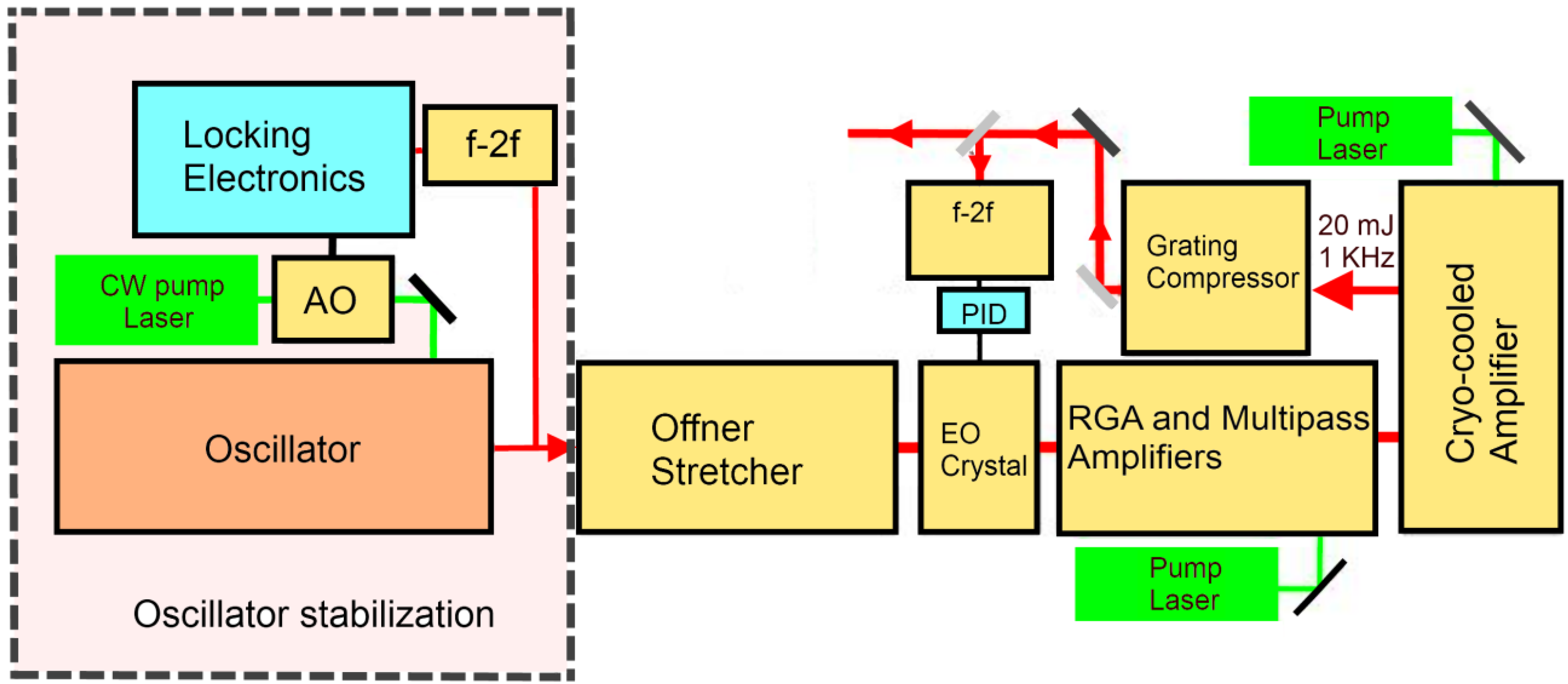
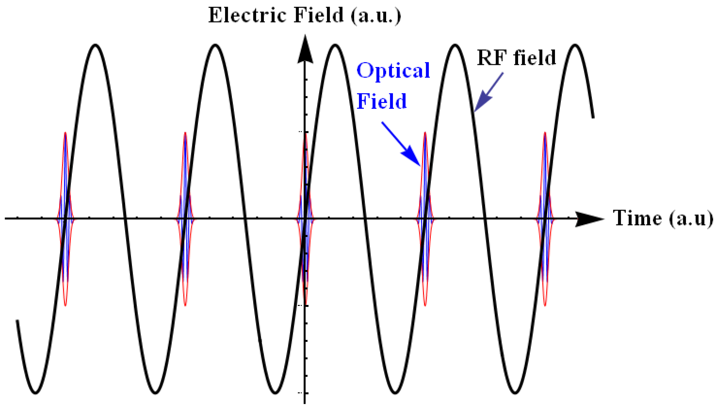
Appendix 5: Discussion on the Possibility to Stabilize the CEP of a ML Laser Oscillator with an EO System, Outside the Oscillator Cavity

 is the period between two pulses, ω0 is the circular carrier wave frequency and ΔϕCE is the phase slippage (modulo 2π) between two pulses. Applying Fourier transform and Fourier series theory, one obtains the following expression [28]:


References
- Goulielmakis, E.; Schultze, M.; Hofstetter, M.; Yakovlev, V.S.; Gagnon, J.; Uiberacker, M.; Aquila, A.L.; Gullikson, E.M.; Attwood, D.T.; Kienberger, R.; et al. Single-cycle nonlinear optics. Science 2008, 320, 1614–1617. [Google Scholar]
- Krausz, F.; Ivanov, M. Attosecond physics. Rev. Mod. Phys. 2009, 81, 163–234. [Google Scholar] [CrossRef]
- Nisoli, M.; Sansone, S. New frontiers in attosecond science. Prog. Quantum Electron. 2009, 33, 17. [Google Scholar] [CrossRef]
- Reichert, J.; Holzwarth, R.; Udem, T.; Hänsch, T.W. Measuring the frequency of light with mode-locked lasers. Opt. Commun. 1999, 172, 59–68. [Google Scholar] [CrossRef]
- Telle, H.R.; Steinmeyer, G.; Dunlop, A.E.; Stenger, J.; Sutter, D.H.; Keller, U. Carrier-envelope offset phase control: A novel concept for absolute optical frequency measurement and ultrashort pulse generation. Appl. Phys. B 1999, 69, 327–332. [Google Scholar]
- Jones, D.J.; Diddams, S.A.; Ranka, J.K.; Stentz, A.; Windeler, R.S.; Hall, J.L.; Cundiff, S.T. Carrier-envelope phase control of femtosecond mode-locked lasers and direct optical frequency synthesis. Science 2000, 288, 635–639. [Google Scholar]
- Kakehata, M.; Takada, H.; Kobayashi, Y.; Torizuka, K.; Fujihira, Y.; Homma, T.; Takahashi, H. Measurements of carrier-envelope phase changes of 100-Hz amplified laser pulses. Appl. Phys. B 2002, 74, S43–S50. [Google Scholar] [CrossRef]
- Baltuška, A.; Paulus, G.G.; Lindner, F.; Kienberger, R.; Krausz, F. Femtosecond Optical Frequency Comb Technology. Principles, Operation and Application; Ye, J., Cundiff, S., Eds.; Springer Science+Business Media: New York, NY, USA, 2005; Volume Chapter 10, pp. 263–307. [Google Scholar]
- Apolonski, A.; Poppe, A.; Tempea, G.; Spielmann, C.; Udem, T.; Holzwarth, R.; Hänsch, T.W.; Krausz, F. Controlling the phase evolution of few-cycle light pulses. Phys. Rev. Lett. 2000, 85, 740–743. [Google Scholar]
- Grebing, C.; Görbe, M.; Osvay, K.; Steinmeyer, G. Isochronic and isodispersive carrier-envelope phase-shift compensators. Appl. Phys. B 2009, 97, 575–581. [Google Scholar] [CrossRef]
- Treacy, E.B. Optical pulse compression with diffraction gratings. IEEE JQE 1969, QE-5, 454–458. [Google Scholar] [CrossRef]
- Chang, Z. Carrier-envelope phase shift caused by grating-based stretchers and compressors. Appl. Opt. 2006, 45, 8350–8353. [Google Scholar] [CrossRef]
- Tournois, P. Acousto-optic programmable dispersive filter for adaptive compensation of group delay time dispersion in laser systems. Opt. Commun. 1997, 140, 245–249. [Google Scholar] [CrossRef]
- Crozatier, V.; Forget, N.; Oksenhendler, T. Toward Single Shot Carrier-Envelope Phase Stabilization for Multi kHz Ultrafast Amplifiers. In Proceedings of the Lasers and Electro-Optics Europe (CLEO EUROPE/EQEC), 2011 Conference on and 12th European Quantum Electronics Conference, Munich, Germany, 22–26 May 2011.
- Canova, L.; Chen, X.; Trisorio, A.; Jullien, A.; Assion, A.; Tempea, G.; Forget, N.; Oksenhendler, T.; Lopez-Martens, R. Carrier-envelope phase stabilization and control using a transmission grating compressor and an AOPDF. Opt. Lett. 2009, 34, 1333–1335. [Google Scholar]
- Kakehata, M.; Takada, H.; Kobayashi, Y.; Torizuka, K. Generation of optical-field controlled high-intensity laser pulses. J. Photochem. Photobiol. A 2006, 182, 220–224. [Google Scholar] [CrossRef]
- Gobert, O.; Paul, P.M.; Hergott, J.F.; Tcherbakoff, O.; Lepetit, F.; D'Oliveira, P.; Viala, F.; Comte, M. Carrier-envelope phase control using linear electro-optic effect. Opt. Express 2011, 19, 5410–5418. [Google Scholar]
- Gobert, O.; Fedorov, N.; Tcherbakoff, O.; Hergott, J.F.; Perdrix, M.; Lepetit, F.; Guillaumet, D.; Comte, M. Measurement of Carrier-Envelope-Phase shifts using spectral interferometry with a broad frequency laser source. Opt. Commun. 2012, 285, 322–327. [Google Scholar]
- Hergott, J.-F.; Tcherbakoff, O.; Paul, P.-M.; Demengeot, Ph.; Perdrix, M.; Lepetit, F.; Garzella, D.; Guillaumet, D.; Comte, M.; D’Oliveira, P.; et al. Grating based, chirped-pulse amplified laser, using Electro-Optic effect in a LiNbO3 crystal. Opt. Express 2011, 19, 19935–19941. [Google Scholar]
- Gobert, O.; Fedorov, N.; Mennerat, G.; Lupinski, D.; Guillaumet, D.; Perdrix, M.; Bourgeade, A.; Comte, M. Wavelength dispersion measurement of electro-optic coefficients in the range of 520 to 930 nm in rubidium titanyl phosphate using spectral interferometry. Appl. Opt. 2012, 51, 594–599. [Google Scholar]
- Weis, R.S.; Gaylord, T.K. Lithium niobate: Summary of physical properties and crystal structure. Appl. Phys. A 1985, 37, 191–203. [Google Scholar] [CrossRef]
- Andrushchak, A.S.; Mytsyk, B.G.; Demyanyshyn, N.M.; Kaidan, M.V.; Yurkevych, O.V.; Solskii, I.M.; Kityk, A.V.; Schranz, W. Spatial anisotropy of linear electro-optic effect in crystal materials: I Experimental determination of electro-optic tensor in LiNbO3 by means of interferometric technique. Opt. Lasers Eng. 2009, 47, 31–38. [Google Scholar] [CrossRef]
- Martinez, O.E.; Gordon, J.P.; Fork, R.L. Negative group-velocity dispersion using refraction. JOSA A 1984, 1, 1003–1006. [Google Scholar] [CrossRef]
- Fork, R.L.; Martinez, O.E.; Gordon, J.P. Negative dispersion using pairs of prisms. Opt. Lett. 1984, 9, 150–152. [Google Scholar] [CrossRef]
- Arissian, L.; Diels, J.C. Carrier to envelope and dispersion control in a cavity with prism pairs. PRA 2007, 75, 1–10. [Google Scholar]
- Mikami, T.; Okamoto, T.; Kato, K. Sellmeier and thermo-optic dispersion formulas for RbTiOPO4. Opt. Mater. 2009, 31, 1628–1630. [Google Scholar] [CrossRef]
- Zvyagin, A.V.; Sampson, D.D. Achromatic optical phase shifter-modulator. Opt. Lett. 2001, 26, 187–189. [Google Scholar] [CrossRef]
- Cundiff, S.T. Phase stabilization of ultrashort optical pulses. J. Phys. D 2002, 35, R43–R59. [Google Scholar] [CrossRef]
- Koke, S.; Grebing, C.; Frei, H.; Anderson, A.; Assion, A.; Steinmeyer, G. Direct frequency comb synthesis with arbitrary offset and shot-noise-limited phase noise Nat. Photonics 2010, 4, 462–465. [Google Scholar] [CrossRef]
- Arfken, G.B.; Weber, H.J. Mathematical Methods for Physicists, 6th ed; Elsevier Academic Press: Burlington, MA, USA, 2005; p. 687. [Google Scholar]
© 2013 by the authors; licensee MDPI, Basel, Switzerland. This article is an open access article distributed under the terms and conditions of the Creative Commons Attribution license (http://creativecommons.org/licenses/by/3.0/).
Share and Cite
Gobert, O.; Rovera, D.; Mennerat, G.; Comte, M. Linear Electro Optic Effect for High Repetition Rate Carrier Envelope Phase Control of Ultra Short Laser Pulses. Appl. Sci. 2013, 3, 168-188. https://doi.org/10.3390/app3010168
Gobert O, Rovera D, Mennerat G, Comte M. Linear Electro Optic Effect for High Repetition Rate Carrier Envelope Phase Control of Ultra Short Laser Pulses. Applied Sciences. 2013; 3(1):168-188. https://doi.org/10.3390/app3010168
Chicago/Turabian StyleGobert, Olivier, Daniele Rovera, Gabriel Mennerat, and Michel Comte. 2013. "Linear Electro Optic Effect for High Repetition Rate Carrier Envelope Phase Control of Ultra Short Laser Pulses" Applied Sciences 3, no. 1: 168-188. https://doi.org/10.3390/app3010168
APA StyleGobert, O., Rovera, D., Mennerat, G., & Comte, M. (2013). Linear Electro Optic Effect for High Repetition Rate Carrier Envelope Phase Control of Ultra Short Laser Pulses. Applied Sciences, 3(1), 168-188. https://doi.org/10.3390/app3010168