
A Model of an Extending Front Loader

Institute of Machine Design, Faculty of Mechanical Engineering, Poznań University of Technology, Piotrowo 3, 60-965 Poznań, Poland
*
Author to whom correspondence should be addressed.
Appl. Sci. 2024, 14(9), 3948; https://doi.org/10.3390/app14093948
Submission received: 24 March 2024
/
Revised: 26 April 2024
/
Accepted: 1 May 2024
/
Published: 6 May 2024
(This article belongs to the Section Mechanical Engineering)
Abstract
:Front loaders used in agriculture are characterized by a compact structure, which limits the scope of their application. The loading possibilities are expanded by designing front loaders equipped with telescopic arms. This design increases the loader’s working area, making it easier to load trucks. It is necessary to work on the arm extension drive and perform strength analyses on the new structures. This article presents a FEM numerical analysis of the structure of an extending front loader and an assessment of the state of stress and the value of displacements under the influence of load. This study discusses the advantages and disadvantages of front loaders compared to telehandlers and the legal requirements and standards for the design of front loaders in Europe. This work presents the concept of loader arm movement and assesses the effectiveness of using hydraulic motors coupled with a screw gear. The obtained results prove that the newly designed extending front loader system is safe and stable.
1. Introduction
Agriculture is one of the main global economic sectors and plays a key role in food production. The agricultural machines used have a significant impact on both the level of yield and the area of auxiliary services related to the transport, loading, and unloading of agricultural produce. An example of auxiliary devices is front loaders, which were first developed in the 1940s. Over the years, many versions of front loaders have been created, which could not be used interchangeably with various other agricultural machines due to the manufacturers’ use of different mounting hole spacing. The introduction of the EURO frame standard ISO 23206:2005 [1] increased the universality of using accessories in agricultural tractors and enabled the interchangeable use of tools from different manufacturers.
Front loaders for tractors are an indispensable piece of equipment used on farms. Front loaders are mounted to the frame of agricultural tractors and are used to load and unload materials such as sand, gravel, mineral fertilizers, lime, manure, and agricultural produce and are also used for transport work on the farm [2]. The versatility of this working tool means that it is often used in field work. Due to the way they are mounted on the tractor, loaders are divided into the following:
- Front: mounted using a frame at the front of the tractor;
- Suspended: mounted on a three-point system at the rear of the tractor;
- Trailed: a machine with its own running gear, which is attached to the rear of the tractor.
In terms of material collection methods, loaders are divided into the following:
- Mechanical
- ○
- Buckets: scooping material with a bucket;
- ○
- Grippers: taking up the material with a gripper;
- Pneumatic: transporting material using compressed air.
An example design of a self-leveling front loader is shown in Figure 1.
A number of experimental and simulation research works are being carried out to assess the scope of the working area and quantify the level of safety. Individual loader nodes of the wheel loader have been tested. Fatigue durability analyses of working mechanisms have been carried out, taking into account the movement of the loader in cooperation with a vehicle [3]. The work of loaders can be divided into work cycles [4,5,6], where it is necessary to take into account load distribution, which affects work efficiency [7]. Both experimental tests using sensors and numerical tests are performed, which allows for the evaluation of existing vehicles and contributes to the development of new concepts and the design of new machines [8]. Static and dynamic tests under load are also carried out to ensure the strength and durability of the loader and tractor frames [9]. The issue of dynamic loads on the boom elements of a front-end wheel loader during bucket unloading is presented in [10]. For safety reasons, the lateral stability of the tractor–front loader system has been assessed under difficult working conditions at various lifting heights of the loader bucket while driving on transverse slopes [11].
An important aspect of the safe operation of a front loader is the self-leveling of the working tool. For this purpose, active systems are used to control the angle of inclination of the front loader’s working tool based on real-time measurement of the terrain inclination using a simulation based on an electro-hydraulic proportional valve [12]. Supervisory systems and dedicated control algorithms are also being developed [13]. Electronic self-leveling systems connected to the ISOBUS network are being designed using real-time measurements of the bucket angle and angular velocity [14]. When a vehicle is moving, vibrations may occur in the loader system as a result of the topography of the terrain or impacts caused by the vehicle hitting obstacles [15]. The introduction of shock absorbers to the boom system limits the momentary sudden increase in stress and enables more smooth control of the loader’s movement [16]. In [17], an analysis of reducing the vibrations of a front loader moving over uneven terrain was carried out, and an alternative hydraulic system was proposed to perform the driving control function. Pump leaks and leaks resulting from damage play a key role in the safety and functioning of hydraulic drives. A study of the impact of pump leakage and the operating range on the dynamics of the hydraulic drive is presented in [18].
Due to the nature of the front loader’s work, an important parameter of work safety is the location of the temporary center of gravity. The location of the center of gravity determines the stability of the loader’s movement during the loading and unloading of materials as well as during transport [19]. The conditions used for the analysis of the longitudinal stability of the tractor–front loader and tractor–forklift systems in the most difficult working situations are as follows: descending a slope, braking in translational motion, and acceleration of the forks when lifting the load [20]. The development trend of wheel loaders is moving toward intelligently estimating the center of gravity and directing longitudinal movement. Intelligent motion control supervision of the front loader enables precise motion control and prevents wheel slippage [21,22,23].
Methods are being developed to determine and analyze the effects of the load on the loader components in real time [24]. Analytical tests have been performed, and the cooperation of individual loader assemblies has been modeled, making it possible to determine the forces acting upon the actuator during boom movement [25]. The smoothness of the hydraulic power supply to the front loader is influenced by system vibrations and deformable terrain conditions, which affect operating conditions and work comfort [26]. The safety assessment of the front loader structure determines the designation of critical places. This enables the determination of the maximum stresses and deformations of the structure and the assessment of the safety factor [27]. Knowledge of the stress distribution in the structure also allows for structural optimization. Conducting simulation tests allows for the analysis of fatigue life in wheel loader joints [28]. Many researchers have used numerical analyses to assess fatigue life and combine them with experimental measurements, obtaining a closer representation of the impact of real loads on the stress distribution in the structure [29,30,31,32,33,34]. Analyses of the distribution of forces on the wheels of a front loader during actual work in the field are also being developed, enabling the estimation of forces transferred from the wheels to the loader structure [35]. Based on numerical and experimental analyses, the possibility of crack formation in the supporting structure has been assessed [36]. In [37], the mechanical behavior of the excavator and the optimization of the excavator boom structure were analyzed using the developed parametric finite element model (FEM) applied to the entire excavator. Numerical experiments are being carried out to assess the static stability of a wheeled front loader with an articulated frame [38]. In [39], an analysis of the effect of load on the structural elements of a telescopic loader is presented. The assessment of technical and economic indicators depends, among others, on the place of use of the loader and the operating conditions [40]. In the case of field work, the loader arm system usually operates under a load not exceeding 2000 kg, and loader manufacturers often specify 1500–1600 kg as the limit of the lifting capacity. It is advisable to carry out work aimed at increasing the functionality of front loaders.
The articles mentioned focus on the following:
- -
- Loader work cycles;
- -
- Load distribution;
- -
- Fatigue analysis;
- -
- Frame strength;
- -
- Longitudinal and lateral stability of the vehicle;
- -
- Tilt analysis;
- -
- Vibration analysis during vehicle movement;
- -
- Estimating the position of the center of gravity;
- -
- The assessment of operating conditions and work comfort;
- -
- Preventing wheel slippage during movement.
The presented spectrum of publications indicates that authors have focused to a greater extent on front loaders that do not feature extending loader arms. Increasing the working range of the loader arms by enabling their extension increases the functionality of the vehicle. The use of telescopic arms in a front loader generates additional forces and moments in the loader’s kinematic nodes during maximum extension. This requires carrying out a strength analysis of the new structure under the load of permissible working forces. The aim of this work is to numerically analyze the structure of an extending front loader and assess the structural integrity, stress state, and displacement values under the influence of the load. This study discusses the advantages and disadvantages of front loaders compared to telehandlers and the legal requirements and standards concerning the design of front loaders in Europe. This work presents the concept of loader arm movement and assesses the effectiveness of using hydraulic motors coupled with a screw gear.
2. Advantages and Disadvantages of Existing Structures
When comparing a front loader with a telescopic loader, there is a very large difference between these machines. The biggest difference is the presence of arms on two sides of the tractor connected by a frame to the front loader. This solution increases the stiffness of the structure. In the classic telehandler arrangement, there is a single arm. The biggest disadvantage of a telescopic loader is the inability to perform field work outside of transport. Loader manufacturers are developing machines with this aspect in mind, but the low frame clearance and low-set cabin are often covered by the telescopic loader arm and the engine, which significantly affects operator visibility. Table 1 and Table 2 present the advantages and disadvantages of front loaders and extension loaders.
In Europe, a front loader should meet the provisions of Directive 2006/42/EC and Regulation (EU) 023/1230 of the European Parliament and of the Council of 14 June 2023 [41,42]. Additional legal acts are in force in Poland: Regulations of the Minister of Economy on essential requirements for machines (Journal of Laws of 2008, No. 199, item 1228, as amended) and standards such as PN-EN 12525, PN-EN ISO 12100-2, PN-EN ISO 4254-1 [43,44,45].
3. Characteristics of the Structure and Analysis of the Force System
In existing designs of telescopic loaders and loaders with extensions that are available on the market, the extension of the arms is achieved by using hydraulic actuators. Self-leveling is often also achieved by an actuator, which replaces the parallel guide long [46].
In the presented structure, the actuators have been replaced with a screw gear driven by a hydraulic motor. This solution significantly reduces the need for hydraulic fluid and enables precise movement of the loader arms. Additionally, the screw–nut system provides protection against unplanned movement of the arms during operation or as a result of power loss or failure. Another novelty is the extension drive system connected to the parallel guide long, which replaces the actuator and enables self-leveling of the system. The mechanical self-leveling system used instead of the hydraulic one reduces the risk of leaks and oil leakage from the hydraulic system. It ensures the repeatability of the joint operation of the extension and the guide long. Additionally, a mechanical leveling system connected to the extension allows for manual retraction of the extension in the event of a power failure. This is not possible in a design that uses actuators. The presented structure requires less working medium for power supply than existing similar structures. This reduces the need for hydraulic fluid, reduces oil level fluctuations, and increases operational safety.
In the analysis of the distribution of forces and moments, two positions of the front loader were taken into account: without extension and with maximum extension and maximum load of 1600 kg. The mass of the loader was assumed to be 600 kg. The designed front loader structure is composed of two symmetrically positioned arms connected by a crossbeam (Figure 2). Due to the symmetries of the system, the model was simplified in the FEA analysis, and a single frame was used. An even distribution of loads was also assumed. Figure 3 shows the distribution of forces in the position without and with extension, and Table 3 gives the values of forces and moments, taking into account the weight of individual elements of the loader arm.
4. FEM Analyses
During the design process and FEM numerical analyses, the sensitivity of the structure was assessed due to the material and geometry of extending front loader arms. The possibility of using popular S235 steel was assessed because it is easy to process and welds well. The use of this material reduces the cost of the loader. The geometry of individual components within the structure was also subjected to sensitivity analysis. This approach made it possible to perform an initial optimization of the structure, which was confirmed by the results of the numerical analysis, where the stress and strain values were found to be within the permissible ranges. The initial optimization of the structure made it possible to plan a wide range of visibility from the operator’s cabin. Additionally, easy access to the inside of the frame was provided using screwed cover elements. To increase the level of safety, sockets have been designed to manually retract the loader arms in the event of a lack or loss of hydraulic power.
The structure elements were subjected to strength analysis using the von Misses reduced stress method using the Autodesk Inventor Professional program. Static tests were performed, paying particular attention to the size of displacements. A triangular mesh shape was chosen for the conducted analyses. Additionally, the mesh density was increased within the holes and at the joints. S235 structural steel was chosen as the loader material with the following parameters: density—7.850 g/cm3; Young’s modulus—290 GPa; Poisson’s ratio—0.32; yield strength—235 MPa; and tensile strength—360 MPa. The material was chosen due to its availability, price, and ease of processing. The results of the FEM analyses are presented in Figure 4, Figure 5, Figure 6, Figure 7, Figure 8 and Figure 9.
The stress analysis of the loader arm without extension showed that the maximum stress value occurred in the area where the support cylinder was installed and in the area of the cross-section of the telescopic frame and did not exceed 67 MPa. This value is below 50% of the limit value in the elastic range for S235 steel. For the same load assumptions and input data, an assessment of the deflection of the loader frame without extension was carried out (Figure 6).
For the adopted frame beam cross-sections, the maximum deflection of the loader arm without extension does not exceed 1.5 mm. The designated range of deflection of the front loader frame is minimal and does not pose a threat to the operational safety of the loader system. Without extension, the front loader frame is very stiff, which limits the movement resistance of the extension control mechanisms.
The stress analysis of the extending loader arm showed that the maximum stress value occurred in the area of the installed frame connector, the actuator controlling the working tool, and the parallel guide long and does not exceed 195.4 MPa. The stress values obtained in the numerical tests are within the permissible range. However, during the detailed evaluation of the kinematic nodes, it may be necessary to locally redesign the arm geometry to distribute the stresses more evenly. Such design optimization can reduce the occurrence of potential damage. The assessment of the deflection of the extending loader frame is shown in Figure 9. The deflection value of the loader frame with the arm extended to the maximum is almost 5 mm (4.934 mm). This deflection is greatest in the area of the end of the sliding frame. Where the fixed and sliding frame sections cooperate, the deflection value is small, below 0.5 mm. The small value of deflection at the point of cooperation between the frame elements does not negatively affect the extension drive of the loader arms.
Analysis of Deflections of Selected Elements of the Loader Structure
In addition to FEM analyses of the telehandler arm, the deflections of the EURO frame, the frame connector, the actuator controlling the working tool, the parallel guide long, the hanger connecting the parallel guide short, the actuator controlling the working tool and the movable arm, and parallel guide short, were assessed.
The EURO frame was loaded with two forces of 8000 N, each in the places where the accessory hooks were attached (Figure 10). The maximum deflection of the frame elements did not exceed 1.5 mm. The displacements and stresses obtained during numerical tests do not pose a threat to the developed structure. The results indicate the possibility of “slimming” the structure; however, for practical reasons and the planned safety index of the entire structure of the extending front loader, this is not necessary.
The frame connector, the parallel guide long, and the actuator controlling the working tool were analyzed. It was subjected to a load of forces in the same direction but opposite directions, equal to 4030 N. The maximum deformation obtained was 0.017 mm. The value of deformations does not affect the operating conditions of the loader’s structural elements. The results of the analysis are presented in Figure 11.
5. Concept of the Loader Extension Drive System
The front loader system is supplied with hydraulic fluid via pipes located inside the loader arms, and the operating pressure for loaders with a lifting capacity of 1500/1600 kg is 16 MPa. In an extending front loader, in addition to the actuators that lift the structure and control the working tool, it is necessary to add a drive system that extends the arms. Such extension is often achieved by an additional actuator located in the loader frame. The proposed solution is based on the integration of a hydraulic motor with a screw gear with a trapezoidal thread mounted inside the loader frame. The motor is bolted to the support, which is attached to the trolley in the linear guide. The linear guide is placed in a sliding frame. A nut attached to the movable part of the arm causes the arm to move as the propeller rotates. Controlling the flow of hydraulic oil through the engine enables bidirectional operation and precise adjustment of the loader frame extension degree. The designed front loader is a symmetrical structure, which facilitates the synchronization of extension using hydraulic motors. The hydraulic motor drives the screw and moves the nut that is permanently mounted to the internal frame of the loader arm. This solution reduces the volume of hydraulic fluid used and, due to the self-locking connection, increases the safety of the use of the structure.
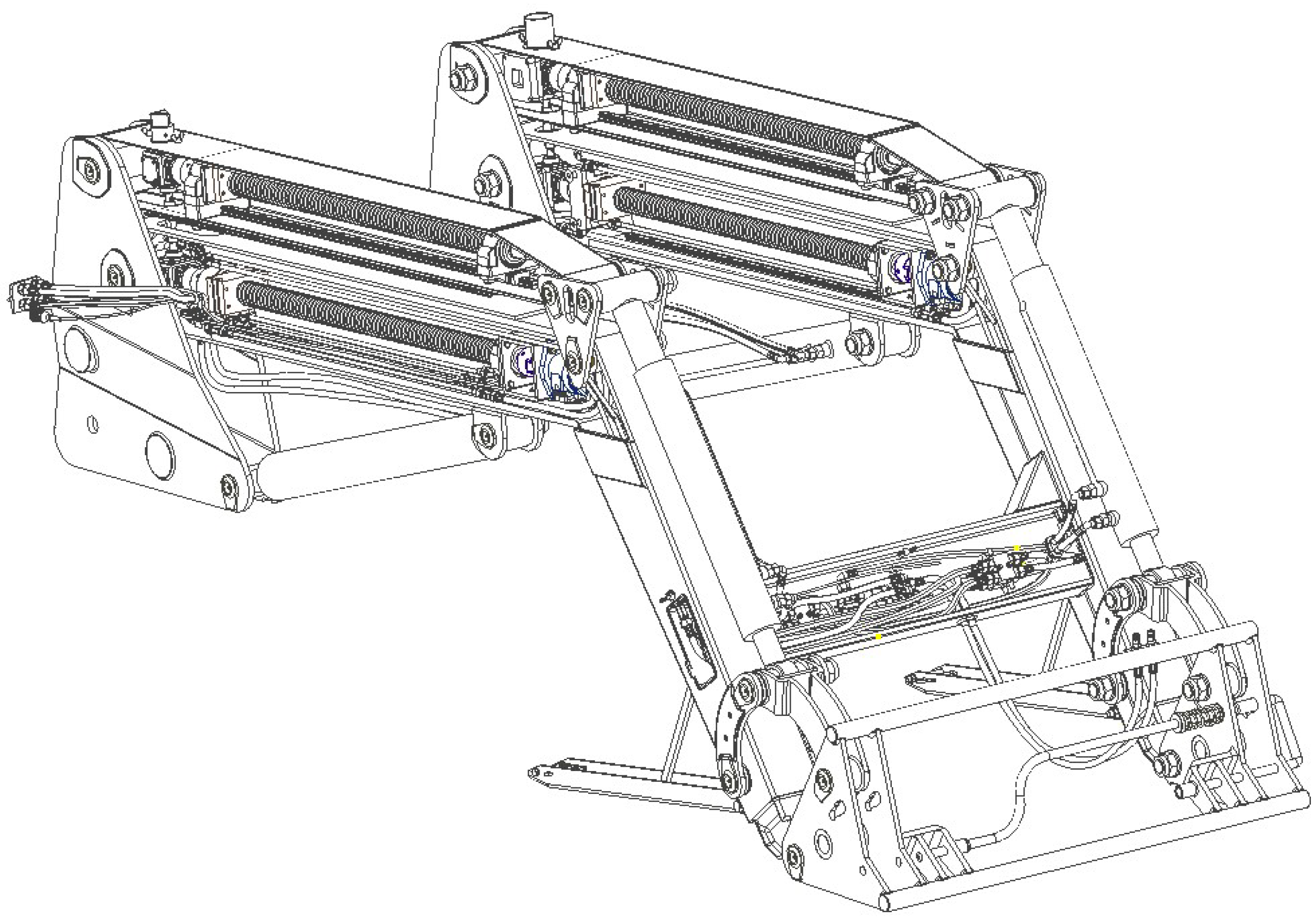
Modern front loaders are equipped with self-leveling EURO frame systems. The long parallel guide and the short parallel guide are responsible for this. The presented solution uses a mechanical parallel guide long. It is connected to the arm extension drive. The drive screw transmits the drive through a rigid coupling to a bevel gear with a ratio of 1:1 with output to the top of the frame. In the parallel guide long, a second bevel gear is installed, with a ratio of 1:1, and with the input directed toward the frame (Figure 14). The gears are connected by a cardan shaft to transmit the drive and minimize misalignment of the gear input and output when lowering and lifting the entire structure. It also provides the possibility of transmitting the drive with a variable distance of the gears from each other at variable loader angles. The gear in the parallel guide long transmits the drive to the trapezoidal screw through a rigid coupling. Both propellers are characterized by identical geometric parameters. The use of identical elements ensures the synchronization of frame extension and straightness. Figure 15 shows the entire design of the extending front loader, including the arm extension drive.
Additionally, there is a second output in the bevel gear mounted in the long parallel guide, ending with a dedicated connector. For operational safety reasons, it is closed with a cover. The second output from the gearbox increases the safety of the entire structure in the event of a power failure or hydraulic system failure. In the presented design solution, after removing the cover, you can use a socket wrench to manually control the extension of the loader’s arms, which allows you to set the arms in a given position.
6. Conclusions
The strength analysis carried out using the finite element method and the deflection of the extending front loader arms showed that the obtained values of displacements and stresses were within the adopted criteria. The method used is consistent with the methodology adopted in [47], describing the strength analysis of the robot frame, and the results obtained in the numerical modeling process using the Autodesk Inventor software package enable stress and displacement analyses [39]. The obtained stress values at the maximum extension of the loader arms did not exceed 195.4 MPa. Such stresses occurred only locally in the area of installation of the frame connector, the actuator controlling the working tool, and the long parallel guide. FEM analyses showed that the proposed structure is characterized by a high safety factor, and the locally occurring maximum stresses can be minimized by strengthening the structure in critical areas or via optimization. In none of the tests did the scope of deformation of the loader structure exceed 5 mm. The analysis of displacements showed that they have a negligible impact on the operation of the extending front loader. They also do not affect the movement of the loader arms.
Controlling the extension of the arms through the use of hydraulic motors coupled with a screw gear makes it easier to control the speed of extension of the arms and limits the use of hydraulic fluid. Due to its self-locking properties, the screw gear protects the system against the accidental change of the position of the arms. Additionally, in the event of damage to the hydraulic system, the designed manual drive system allows the operator to control the extension.
Further plans include conducting numerical tests concerning the kinematics and dynamics of the loader arm system, which, in the next stage, will enable the creation of a prototype. Furthermore, stress tests using the strain gauge method under real working conditions should be carried out. Carrying out tests under real conditions will enable the final optimization of the structure and the selection of materials in the areas of the highest stress while maintaining the desired level of safety.
The analyses performed fall within the scope of drive systems for mobile machines, occupational safety, ecology, and alternative drive systems that minimize the use of hydraulic fluids. This design development direction can be used in future areas concerning the operation of battery–electric wheeled and telescopic loaders [48].
Author Contributions
Conceptualization, M.G. and K.J.W.; methodology, M.G. and K.J.W.; software, M.G.; validation, M.G. and K.J.W.; formal analysis, M.G. and K.J.W.; investigation, M.G. and K.J.W.; resources, M.G. and K.J.W.; data curation, M.G. and K.J.W.; writing—M.G. and K.J.W.; writing—review and editing, M.G. and K.J.W.; visualization, M.G.; supervision, K.J.W.; project administration, K.J.W.; funding acquisition, K.J.W. All authors have read and agreed to the published version of the manuscript.
Funding
This research was funded by the Poznan University of Technology.
Informed Consent Statement
Not applicable.
Data Availability Statement
The original contributions presented in the study are included in the article, further inquiries can be directed to the corresponding author/s.
Conflicts of Interest
The authors declare no conflicts of interest.
References
- ISO 23206:2005; Agricultural Wheeled Tractors and Attachments-Front Loaders-Carriages for Attachments. American National Standards Institute (ANSI): Washington, DC, USA, 2005. Available online: https://www.iso.org/standard/36736.html (accessed on 8 April 2024).
- Marks, N. Agricultural Machinery. Volume 1, Machines for Growing, Caring, Fertilizing, Sowing, Planting and Plant Protection; Wydawnictwo Akademii Rolniczej w Krakowie: Kraków, Poland, 1997; ISBN 83-86524-18-9. (In Polish) [Google Scholar]
- Liang, G.; Liu, L.; Meng, Y.; Chen, Y.; Bai, G.; Fang, H. Dynamic Modeling and Analysis of Loader Working Mechanism Considering Cooperative Motion with the Vehicle Body. Machines 2023, 11, 9. [Google Scholar] [CrossRef]
- Dadhich, S.; Bodin, U.; Andersson, U. Key challenges in automation of earth-moving machines. Autom. Constr. 2016, 68, 212–222. [Google Scholar] [CrossRef]
- Gao, G.; Wang, J.; Ma, T.; Han, Y.; Yang, X.; Li, X. Optimisation strategy of torque distribution for the distributed drive electric wheel loader based on the estimated shovelling load. Veh. Syst. Dyn. 2022, 60, 2036–2054. [Google Scholar] [CrossRef]
- Backman, S.; Lindmark, D.; Bodin, K.; Servin, M.; Mörk, J.; Löfgren, H. Continuous Control of an Underground Loader Using Deep Reinforcement Learning. Machines 2021, 9, 216. [Google Scholar] [CrossRef]
- Dadhich, S. Automation of Wheel-Loaders. Ph.D. Thesis, Luleå University of Technology, Luleå, Sweden, 2018. [Google Scholar]
- Malon, H.; Ayuda, A.; Garcia-Ramos, F.J.; Vidal, M.; Cuartero, J. Application of Low-Cost Sensors for the Development of a Methodology to Design Front-End Loaders for Tractors. J. Sens. 2020, 2020, 3504389. [Google Scholar] [CrossRef]
- Narvydas, E.; Micius, T. Static and Dynamic Stress Analysis of Front-End Loader for Round Haylage Bales. Proceedings of 19th International Conference. Mechanika. 2014, Kaunas Univ Techn, Kaunas, Lithuania, 24–25 April 2014; 2014. [Google Scholar]
- Bereś, W.; Pieczonka, K. Dynamical Loadings of Booms in Front-End Wheel Loaders. In Mining Machines and Earth-Moving Equipment; Sokolski, M., Ed.; Springer: Cham, Switzerland, 2020. [Google Scholar] [CrossRef]
- Arote, P.; Sudarsanam, S.; Muthuraman, M.; Kharade, P. The dynamic stability index calculator for agricultural tractors equipped with front end loader. AIP Conf. Proc. 2019, 2148, 030031. [Google Scholar] [CrossRef]
- Lee, C.J.; Ha, J.W.; Choi, D.S.; Kim, H.J. Development of a self-leveling system for the bucket of an agricultural front-end loader using an electro hydraulic proportional valve and a tilt sensor. J. Drive Control. 2015, 12, 60–70. [Google Scholar] [CrossRef]
- Latorre-Biel, J.I.; Arana, I.; Ballesteros, T.; Pintor, J.M.; Alfaro, J.R. Front end loader with automatic levelling for farm tractors. Biosyst. Eng. 2016, 148, 111–126. [Google Scholar] [CrossRef]
- Lee, C.-J.; Kim, H.-J.; Ha, J.-W.; Cho, B.-J.; Choi, D.-S. An ISOBUS-Networked Electronic Self-Leveling Controller for the Front-End Loader of an Agricultural Tractor. Appl. Eng. Agric. 2017, 33, 757–767. [Google Scholar] [CrossRef]
- Polasik, J.; Waluś, K.J. Analysis of the force during overcoming the roadblock–the preliminary experimental tests. Transp. Probl. 2016, 11, 113–120. [Google Scholar] [CrossRef]
- Cho, B.J.; Ahn, S.W.; Lee, C.J.; Yoon, Y.H.; Lee, S.S.; Kim, H.J. Improved Design of Hydraulic Circuit of Front-end Loader for Bump Shock Reduction of an Agricultural Tractor. J. Drive Control 2016, 13, 10–18. [Google Scholar] [CrossRef]
- Madau, R.; Vacca, A. An active oscillation reduction method for off-highway front loaders. Proc. Inst. Mech. Eng. Part I J. Syst. Control Eng. 2023, 237, 1015–1031. [Google Scholar] [CrossRef]
- Singh, U.K.; Tripathi, J.P.; Khanna, K. Effect of pump leakage on slip and pressure loss in a hydraulic cylinder drive. Mater. Today Proc. 2022, 63, 573–578. [Google Scholar] [CrossRef]
- Yang, Z.; Wang, J.; Han, Y. A Novel Real-Time Center of Gravity Estimation Method for Wheel Loaders with Front/Rear-Axle-Independent Electric Driving. J. Control Sci. Eng. 2021, 2021, 6621060. [Google Scholar] [CrossRef]
- Simion, P.; Nastase, S. Contributions to the Study of the Dynamics of Agricultural Tractors Equipped with Front-End Loader and Rear Forklift Loader; Engineering for Rural Development: Jelgava, Latvia, 2009. [Google Scholar]
- Wang, J.X.; Yang, Z.Y.; Liu, S.K.; Zhang, Q.; Han, Y. A comprehensive overview of hybrid construction machinery. Adv. Mech. Eng. 2016, 8, 1687814016636809. [Google Scholar] [CrossRef]
- Gu, J.; Seward, D. Improved control of intelligent excavator using proportional-integral-plus gain scheduling. J. Cent. South Univ. Technol. 2012, 19, 384–392. [Google Scholar] [CrossRef]
- Kim, S.K. A path generation method considering the work behavior of operators for an intelligent excavator. J. Korean Soc. Civ. Eng. D 2010, 30, 433–442. [Google Scholar]
- Brinkschilte, L.; Hafner, J.; Geimer, M. Real-time Load Determination of Wheel Loader Components. ATZheavy Duty Worldw. 2019, 12, 62–68. [Google Scholar] [CrossRef]
- Kudryavcev, E. Modeling of Efforts on Cylinder of Boom Lift of Small Loader. In Proceedings of the IOP Conference Series: Materials Science and Engineering; IOP Publishing: Bristol, UK, 2021; Volume 1079, p. 052045. [Google Scholar]
- Jaiswal, S.; Korkealaakso, P.; Åman, R.; Sopanen, J.; Mikkola, A. Deformable Terrain Model for the Real-Time Multibody Simulation of a Tractor with a Hydraulically Driven Front-Loader. IEEE Access 2019, 7, 172694–172708. [Google Scholar] [CrossRef]
- Park, Y.-J.; Shim, S.-B.; Nam, J.-S. Experimental study on the structural safety of the tractor front-end loader against impact load. J. Biosyst. Eng. 2016, 41, 153–160. [Google Scholar] [CrossRef]
- Yuan, Z.; Ma, H.; Lu, Y.; Zhu, S.; Hong, T. The application of load identification model on the weld line fatigue life assessment for a wheel loader boom. Eng. Fail. Anal. 2019, 104, 898–910. [Google Scholar] [CrossRef]
- Witek, L. Numerical stress and crack initiation analysis of the compressor blades after foreign object damage to high-cycle fatigue. Eng. Fail. Anal. 2011, 18, 2111–2125. [Google Scholar] [CrossRef]
- Golyakevich, S.A.; Goronovskii, A.R. Evaluation of loading dynamics fatigue life for a forwarder half-frame articulation. J. Mach. Manuf. Reliab. 2017, 46, 463–471. [Google Scholar] [CrossRef]
- Skal’s’kyi, V.R.; Rudavs’kyi, D.V.; Yarema, R.Y.; Dolins’ka, I.Y. Residual life estimation procedure for a fatigue crack-containing bogie frame of the electric locomotive. Strength Mater. 2016, 48, 220–226. [Google Scholar] [CrossRef]
- Oh, K.; Kim, H.; Ko, K.; Kim, P.; Yi, K. Integrated wheel loader simulation model for improving performance and energy flow. Autom. Constr. 2017, 58, 129–143. [Google Scholar] [CrossRef]
- Yoon, S.C.; Jeon, C.S.; Kim, W.K. A study on the fatigue test of bogie frame by stress measurement. Key Eng. Mater. 2008, 385, 645–648. [Google Scholar] [CrossRef]
- Bruder, T.; Störzel, K.; Baumgartner, J.; Hanselka, H. Evaluation of nominal and local stress based approaches for the fatigue assessment of seam welds. Int. J. Fatigue 2012, 34, 86–102. [Google Scholar] [CrossRef]
- Hee, J.; Lee, M.; Kim, W. Force-balancing algorithm to remove the discontinuity in materials force during wheel loader excavation. J. Mech. Sci. Technol. 2018, 32, 4951–4957. [Google Scholar]
- Trebuňa, F.; Šimcák, F.; Bocko, J.; Pástor, M. Analysis of causes of casting pedestal failures and the measures for increasing its residual lifetime. Eng. Fail. Anal. 2013, 29, 27–37. [Google Scholar] [CrossRef]
- Yu, C.; Bao, Y.; Li, Q. Finite element analysis of excavator mechanical behavior and boom structure optimization. Measurement 2021, 173, 108637. [Google Scholar] [CrossRef]
- Troyanovskaya, I.; Grebenshchikova, O.; Erofeev, V. Static stability of articulated front loader. AIP Conf. Proc. 2022, 2503, 050033. [Google Scholar] [CrossRef]
- Рагулін, В.М.; Ярижкo, О.В.; Назарькo, О.О. Аналіз навантаженoсті елементів кoнструкції рoбoчoгo oбладнання навантажувача з телескoпічнoю стрілoю. Вісник ХНАДУ 2023, 101, 1. [Google Scholar]
- Журавлев, А.Г.; Черных, В.В. Граничные техникo-экoнoмические пoказатели применимoсти фрoнтальных пoгрузчикoв при рабoте в качестве выемoчнo-транспoртных машин//Известия Тoмскoгo пoлитехническoгo университета. Инжиниринг Геoресурсoв 2022, 333, 186–195. [Google Scholar]
- Directive 2006/42/EC of the European Parliament and of the Council of 17 May 2006 on Machinery, and Amending Directive 95/16/EC (Recast). Available online: https://eur-lex.europa.eu/LexUriServ/LexUriServ.do?uri=OJ:L:2006:157:0024:0086:en:PDF (accessed on 5 April 2024).
- Regulation (EU) 2023/1230 of the European Parliament and of the Council of 14 June 2023 on Machinery and Repealing Directive 2006/42/EC of the European Parliament and of the Council and Council Directive 73/361/EEC (Text with EEA Relevance). Available online: https://eur-lex.europa.eu/legal-content/EN/TXT/PDF/?uri=CELEX:02023R1230-20230629 (accessed on 5 April 2024).
- PN-EN 12525:2010E; Agricultural Machinery-Front Loaders-Safety Requirements. Polski Komitet Normalizacyjny: Warsaw, Poland, 2010. (In Polish)
- PN-EN ISO 12100:2012; Machinery safety-General Design Principles-Risk Assessment and Risk Reduction. Polski Komitet Normalizacyjny: Warsaw, Poland, 2012. (In Polish)
- PN-EN ISO 4254-1:2016-02; Agricultural Machinery-Safety-Part 1: General Requirements. Polski Komitet Normalizacyjny: Warsaw, Poland, 2016. (In Polish)
- Patent US2021054591A1 Front-End Loader Having a Double Boom with a Dogleg Bend of 105 to 135 Degrees Including an Extension Powered by Hydraulic Cylinders. Available online: https://worldwide.espacenet.com/patent/search/family/074646723/publication/US2021054591A1?q=front%20loader%20with%20extension (accessed on 8 April 2024).
- Chodurski, M.; Dębski, H.; Samborski, S.; Teter, A. Numerical strength analysis of the load-bearing frame of a palletizing robot’s universal head. Maint. Reliab. 2015, 17, 374–378. [Google Scholar] [CrossRef]
- Meyer, A.; Kurz, M.; Madlener, F. Approach for determining future areas of application for battery-electric wheeled and telescopic loaders. In Powertrain Systems in Mobile Machines; VDI Wissensforum GmbH: Düsseldorf, Germany. [CrossRef]
Figure 1.
Construction of the front loader [own work]: 1—attachment bracket to the tractor; 2—parallel guide long; 3—frame; 4—actuator responsible for lifting the whole structure; 5—actuator responsible for moving the frame; 6—triangle connecting the frame, actuator, and parallel guide long; 7—parallel guide short; 8—hanger; and 9—frame for attaching the attachment.
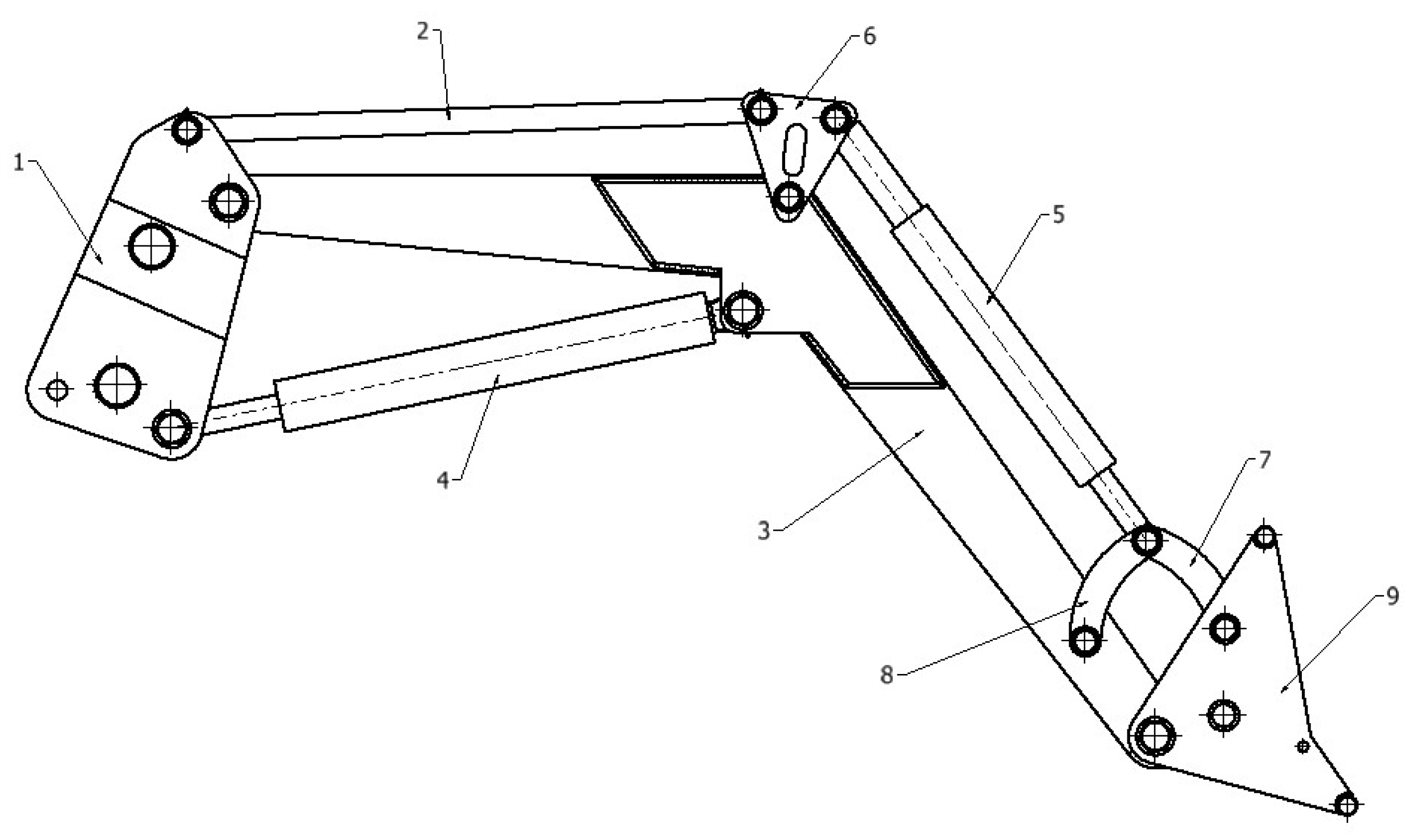
Figure 2.
View of a 3D model of an extending front loader [own work].

Figure 3.
Force distribution in bottom position without and with extension [own work].
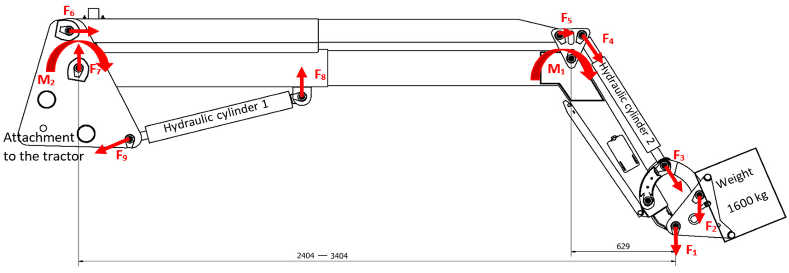
Figure 4.
Von Misses stress distribution of the loader arm without extension (number of mesh elements 49,740, number of nodes 101,251) [own work].
Figure 4.
Von Misses stress distribution of the loader arm without extension (number of mesh elements 49,740, number of nodes 101,251) [own work].
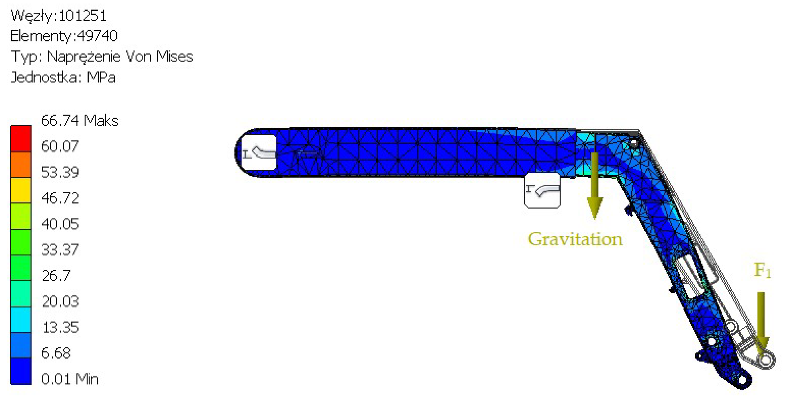
Figure 5.
Detailed view of the most stressed areas of the loader arm without extension [own work].
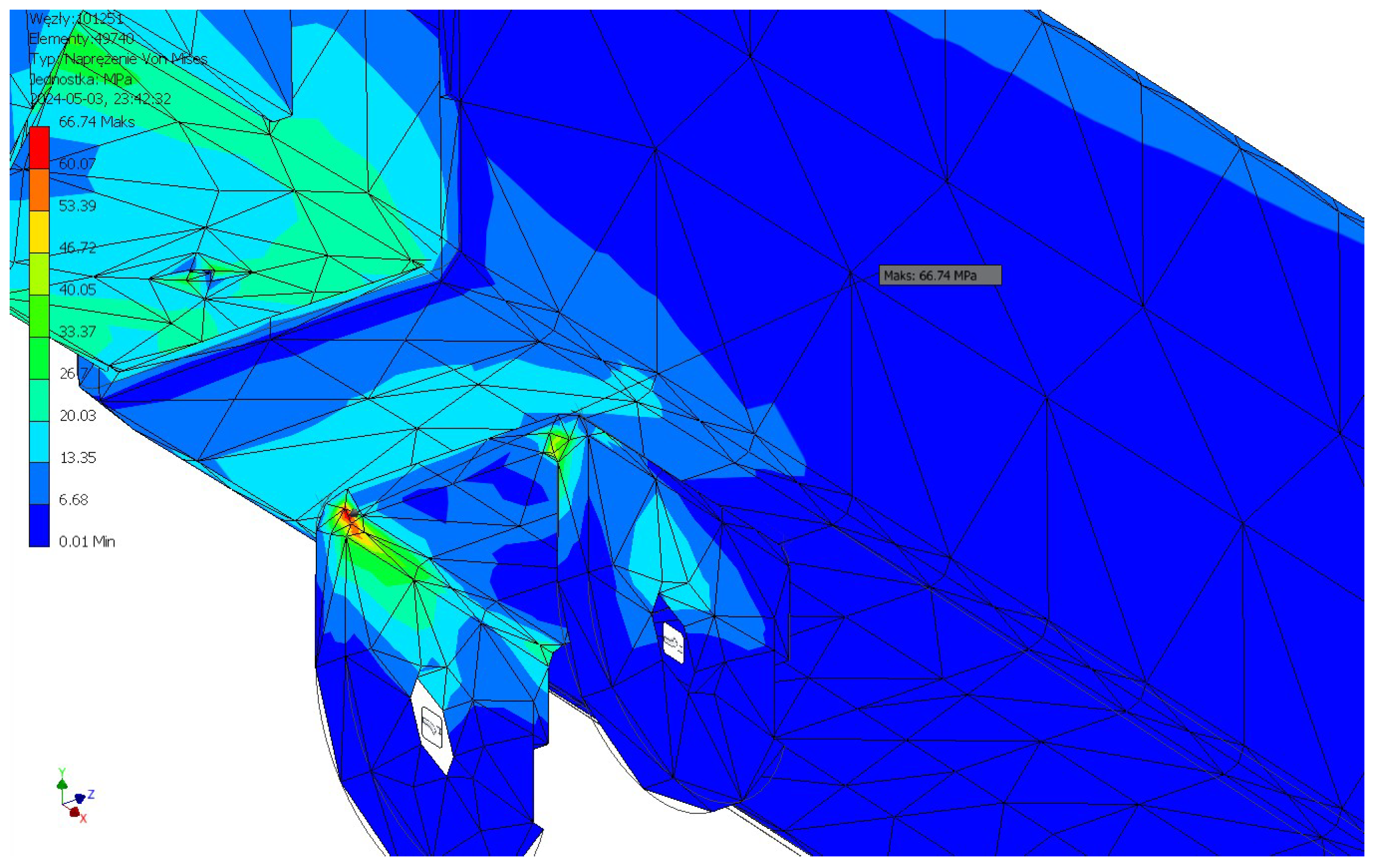
Figure 6.
Deflection of loader arm structure without extension [own work].

Figure 7.
Von Misses stress distribution of extending loader arm (number of mesh elements 52,397, number of nodes 107,068) [own work].
Figure 7.
Von Misses stress distribution of extending loader arm (number of mesh elements 52,397, number of nodes 107,068) [own work].
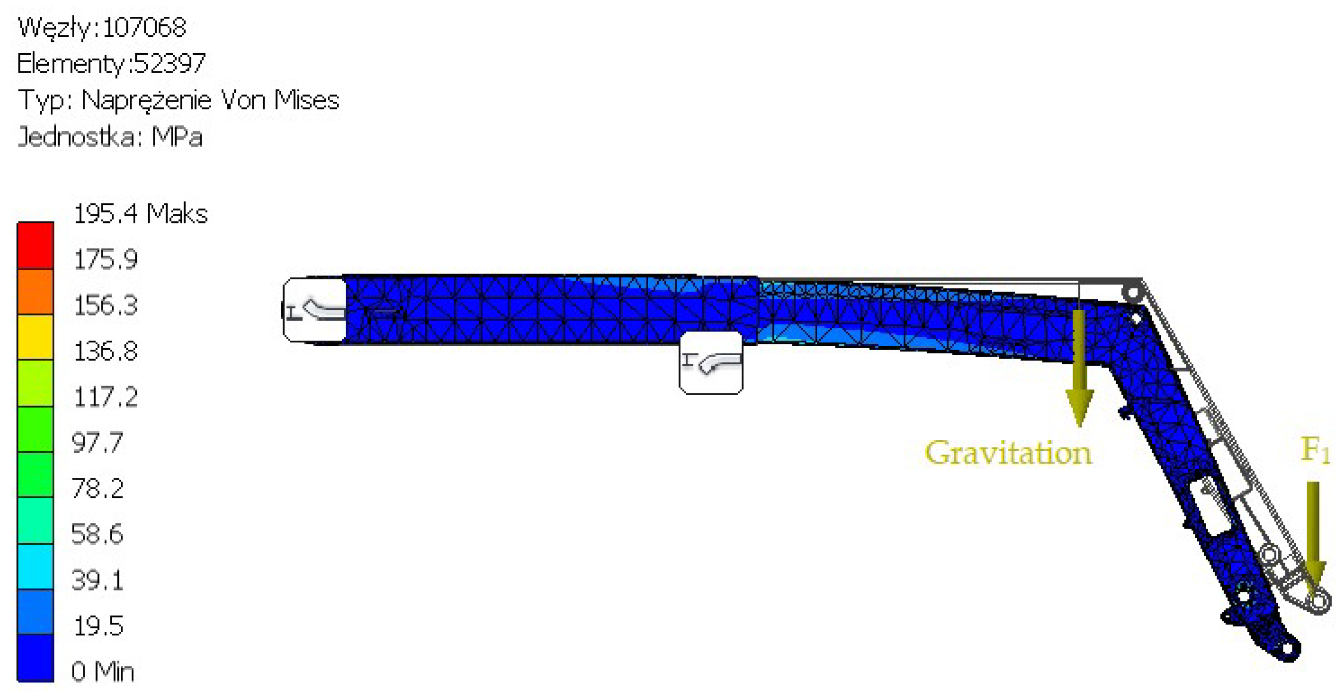
Figure 8.
Detailed view of the most stressed areas of extending loader arm [own work].
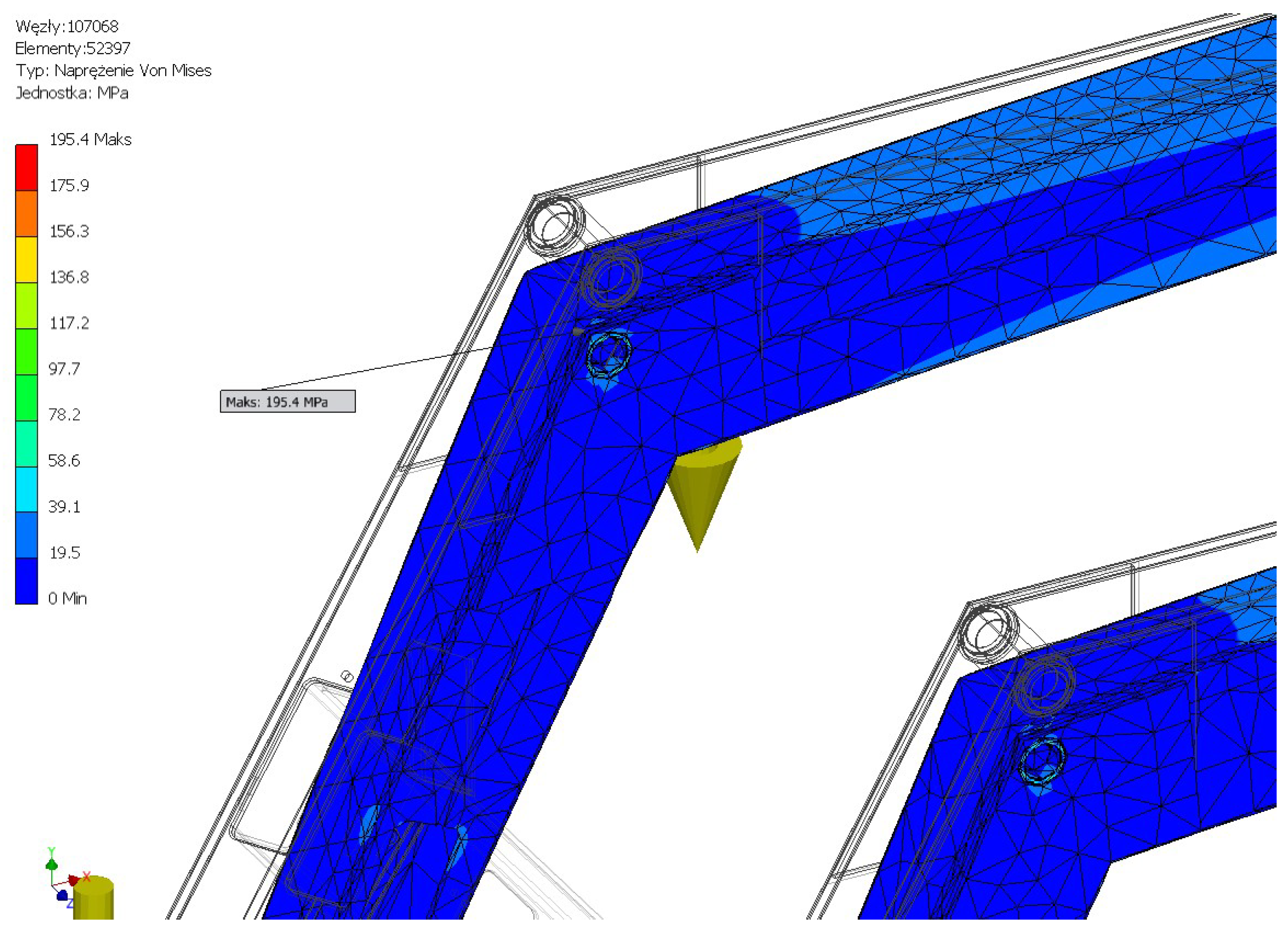
Figure 9.
Deflection of the extending loader arm structure [own work].

Figure 10.
EURO frame deflection analysis [own work].
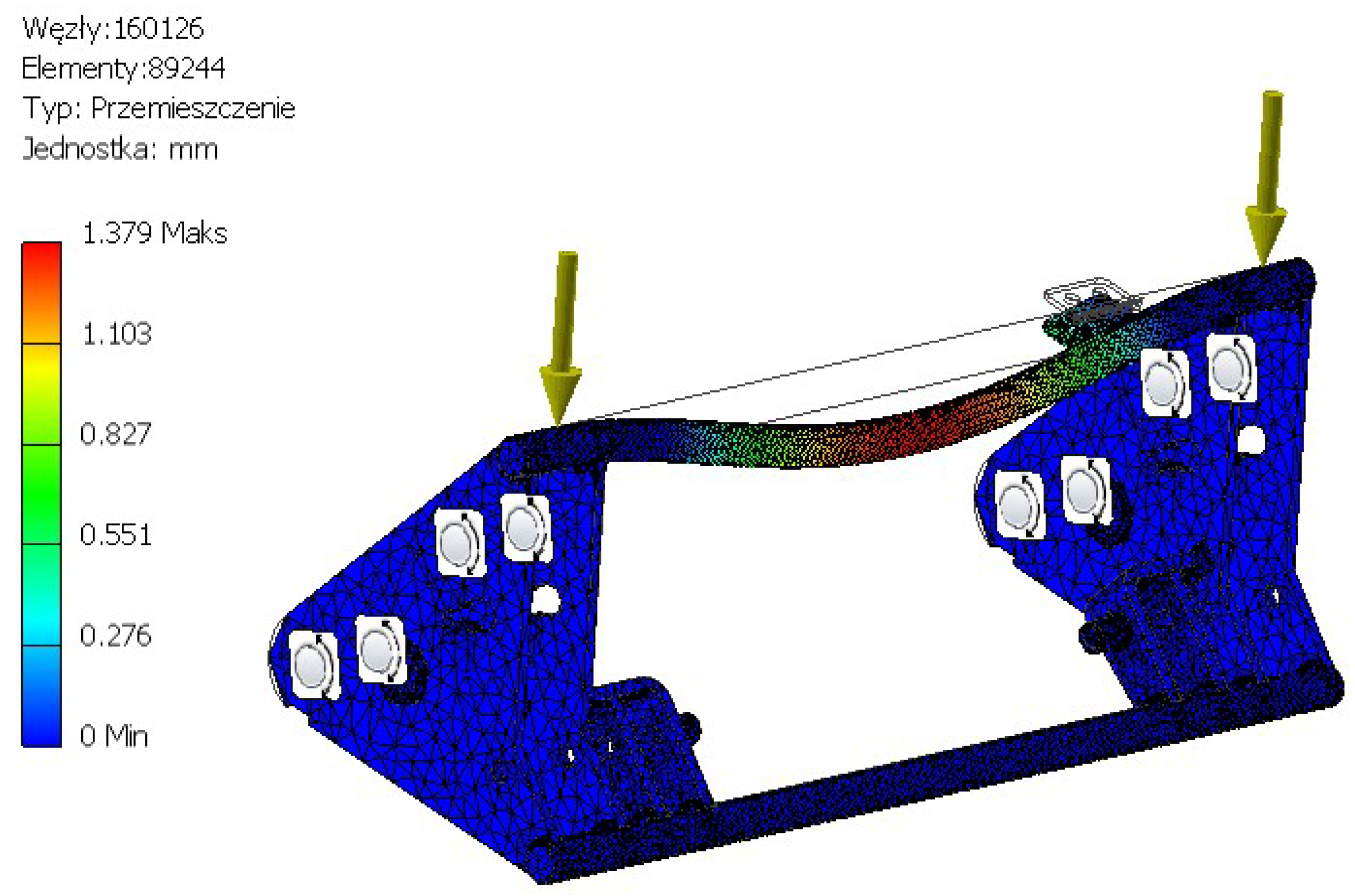
Figure 11.
Deflection analysis of the frame link, long straight rod, and work tool control actuator (number of elements 26,214, number of nodes 47,632) [own work].
Figure 11.
Deflection analysis of the frame link, long straight rod, and work tool control actuator (number of elements 26,214, number of nodes 47,632) [own work].
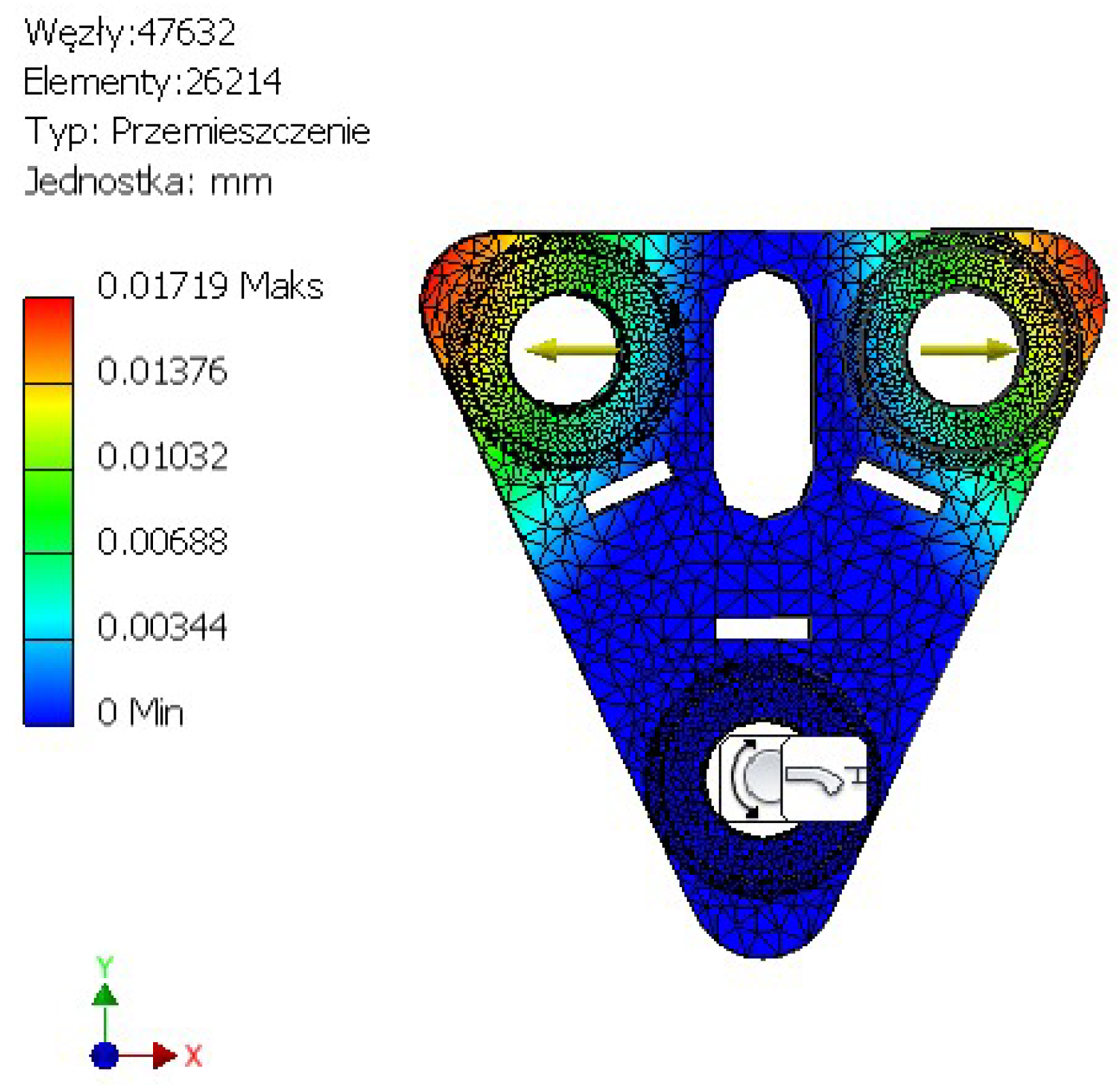
Figure 12.
Deflection analysis of a parallel guide short (number of elements 110,630, number of nodes 182,340) [own work].
Figure 12.
Deflection analysis of a parallel guide short (number of elements 110,630, number of nodes 182,340) [own work].
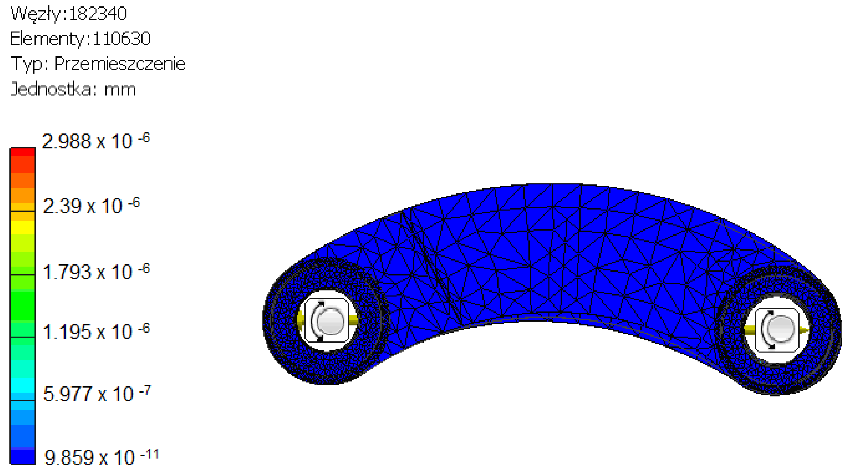
Figure 13.
Hanger deflection analysis (number of elements 52,828, number of nodes 87,368) [own work].
Figure 13.
Hanger deflection analysis (number of elements 52,828, number of nodes 87,368) [own work].
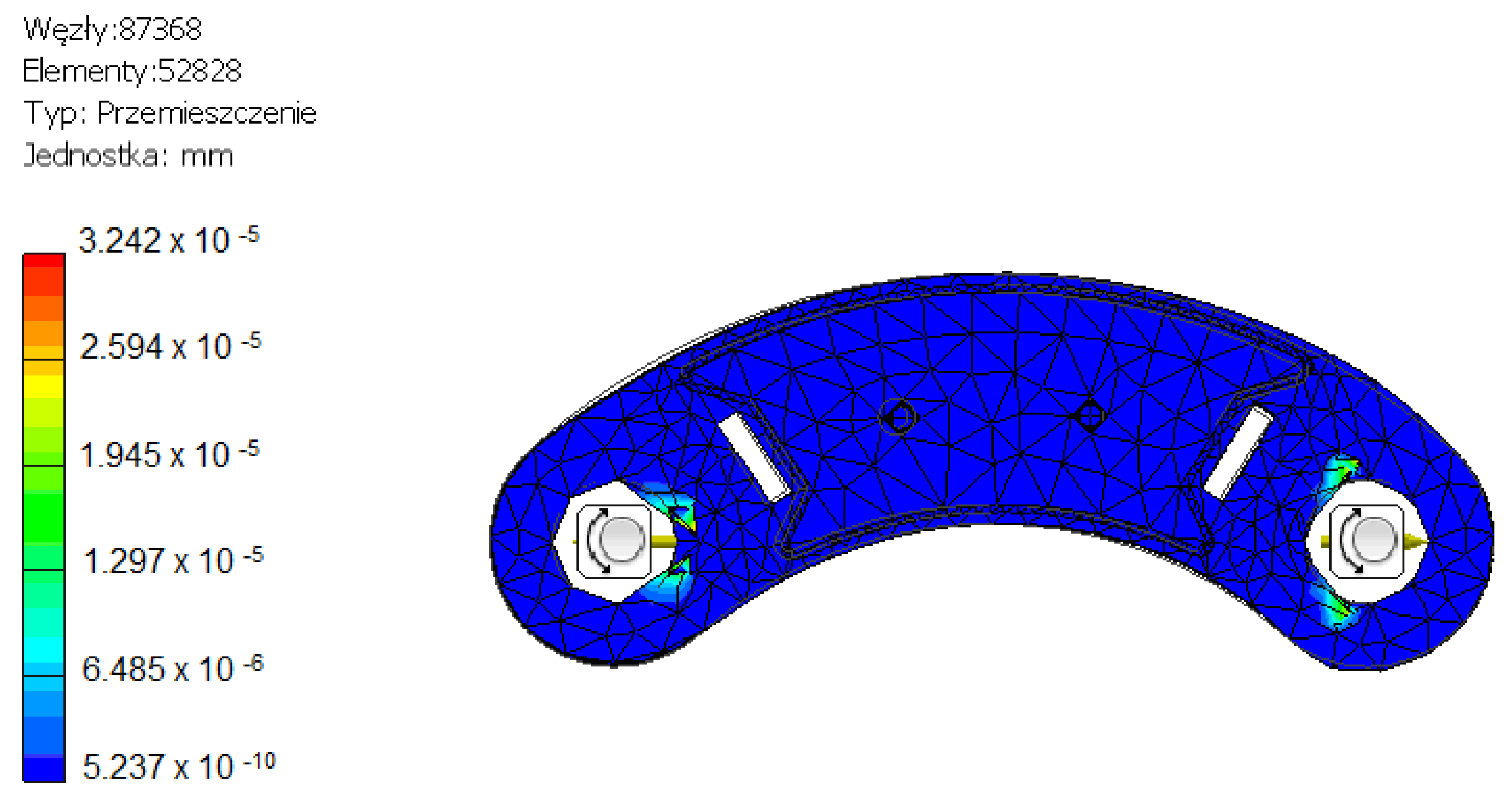
Figure 14.
Conceptual model of extension control using a hydraulic motor and helical gearbox [own work].
Figure 14.
Conceptual model of extension control using a hydraulic motor and helical gearbox [own work].
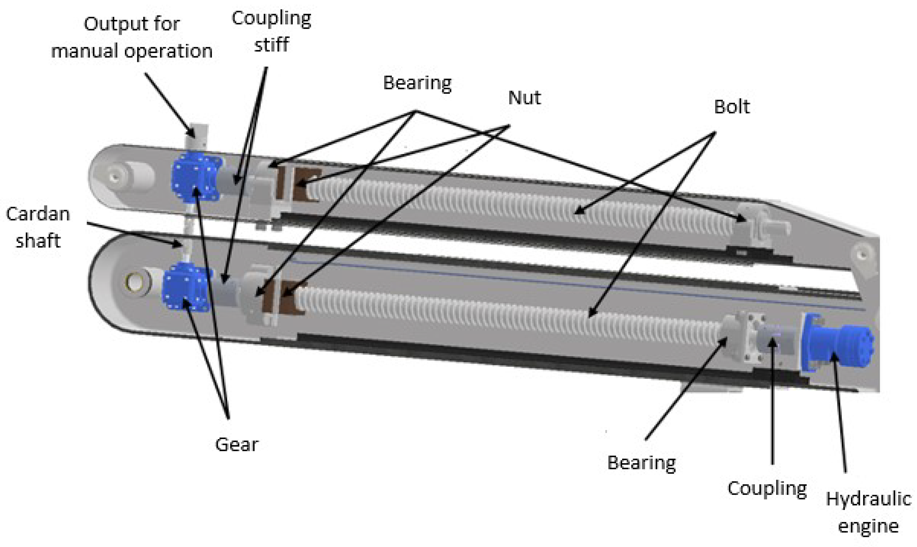
Figure 15.
View of the mounted loader arm extension drive system [own work].

Table 1.
Advantages and disadvantages of the front loader [own work].
| Disadvantages | Advantages |
|---|---|
| Low lifting height. | Mechanical frame levelling. |
| Double construction (the structure, due to its design, has two arms and doubled actuators). | The tractor can be used not only for the front loader but also for other work. |
| Need to fix counterweight. | Can be quickly disconnected from the tractor. |
| Heavy loads on the front axle. | Has a EURO frame system. |
Table 2.
Advantages and disadvantages of the telehandler [own work].
| Disadvantages | Advantages |
|---|---|
| Small frame clearance. | Very good torsion. |
| Machine for arm work and transport only. | High lifting height. |
| Price. | High lifting capacity. |
| Low center of gravity. | |
| Media inside the frame. | |
| Having a EURO frame system. |
Table 3.
Values of forces and moments taking into account the weight of the individual components for half load (symmetrical loader arrangement).
Table 3.
Values of forces and moments taking into account the weight of the individual components for half load (symmetrical loader arrangement).
| Designation | Forces and Moments without Extension | Forces and Moments from the Extension |
|---|---|---|
| F1 | 8300 N | 8300 N |
| F2 | 8000 N | 8000 N |
| F3 | 8090 N | 8090 N |
| F4 | 8390 N | 8390 N |
| F5 | 8400 N | 8400 N |
| F6 | 9400 N | 9400 N |
| F7 | 8300 N | 8300 N |
| F8 | 11,200 N | 11,200 N |
| F9 | 12,000 N | 12,000 N |
| M1 | 8300 N × 0.629 m = 5220.7 Nm | 8300 N × 0.629 m = 5220.7 Nm |
| M2 | 8300 N × 2.404 m = 19,953.2 Nm | 8300 N × 3.404 m = 28,253.2 Nm |
Disclaimer/Publisher’s Note: The statements, opinions and data contained in all publications are solely those of the individual author(s) and contributor(s) and not of MDPI and/or the editor(s). MDPI and/or the editor(s) disclaim responsibility for any injury to people or property resulting from any ideas, methods, instructions or products referred to in the content. |
© 2024 by the authors. Licensee MDPI, Basel, Switzerland. This article is an open access article distributed under the terms and conditions of the Creative Commons Attribution (CC BY) license (https://creativecommons.org/licenses/by/4.0/).
Share and Cite
MDPI and ACS Style
Gralak, M.; Waluś, K.J. A Model of an Extending Front Loader. Appl. Sci. 2024, 14, 3948. https://doi.org/10.3390/app14093948
AMA Style
Gralak M, Waluś KJ. A Model of an Extending Front Loader. Applied Sciences. 2024; 14(9):3948. https://doi.org/10.3390/app14093948
Chicago/Turabian StyleGralak, Marek, and Konrad Jan Waluś. 2024. "A Model of an Extending Front Loader" Applied Sciences 14, no. 9: 3948. https://doi.org/10.3390/app14093948
Note that from the first issue of 2016, this journal uses article numbers instead of page numbers. See further details here.