

Compressive Characteristics and Energy Absorption Capacity of Automobile Energy-Absorbing Box with Filled Porous TPMS Structures

College of Mechanical and Electrical Engineering, China University of Petroleum, Qingdao 266580, China
*
Author to whom correspondence should be addressed.
Appl. Sci. 2024, 14(9), 3790; https://doi.org/10.3390/app14093790
Submission received: 3 April 2024
/
Revised: 25 April 2024
/
Accepted: 27 April 2024
/
Published: 29 April 2024
(This article belongs to the Special Issue Additively Manufactured Mechanical Metamaterials: Design, Analysis, and Applications)
Abstract
:In order to meet the higher requirements of energy-absorbing structures in the lightweight automobile design, the mechanical design and impact energy absorption of porous TPMS structures are studied. Eight kinds of porous TPMS structure elements, Gyroid, Diamond, I-WP, Neovius, Primitive, Fischer-Koch S, F-RD, and PMY, are designed based on Matlab, and the porous structure samples composed of eight elements are printed and molded using SLM. The deformation mechanism, mechanical response, and energy absorption characteristics of different porous TPMS structures are investigated. Gyroid and Primitive elements are selected to fill the internal structure of the energy-absorbing automobile boxes. Traditional thin-walled energy-absorbing boxes served as a control group and were subjected to low-speed impact testing. The results show that the peak load of the energy-absorbing box filled with TPMS porous structures is almost equal to the average load under a 4.4 m/s impact, and the SEA of the energy-absorbing box filled with TPMS porous structures is higher than the traditional thin-walled energy-absorbing box. The problems of excessive peak load and inconsistent load fluctuation of traditional thin-walled energy-absorbing structures are effectively solved by porous TPMS structures with the assurance that the lightweight and energy-absorbing requirements are still met.
1. Introduction
The proposal of dual carbon targets has brought unprecedented challenges to the automobile industry, requiring car manufacturers to rethink their plant operations and sustainability goals [1]. Manufacturers prioritize lightweight automobiles as one of the most essential energy-saving and emission-reduction measures [2]. As a high-speed mobile manned vehicles, when the automobile collides, it poses a considerable threat to the personal safety of the occupants. Studying the performance of the car’s passive safety system is essential, as it can significantly affect the final injury of the occupants [3], absorbing the energy generated by the collision and improving the overall safety of vehicles put forward higher requirements for lightweight, impact-resistant, and energy-absorbing structures.
In impact applications, the porous structure can realize a unique combination of lightweight and superior load-carrying capacity due to its high porosity and microstructural designability. According to the order of the smallest constituent unit, porous structure can be divided into stochastic structure and nonstochastic structure. The main representative of stochastic structure is foam structure [4], and nonstochastic structure can be divided into two-dimensional nonstochastic structure and three-dimensional nonstochastic structure. The representative of two-dimensional nonstochastic structures is honeycomb structure [5,6,7,8,9,10], while the main representative of three-dimensional nonstochastic structure is lattice structure [11,12,13,14,15,16]. As a new type of nonsolid lightweight structure, lattice structure has many excellent characteristics. Its high specific strength and high specific stiffness can greatly reduce material loss while ensuring bearing capacity, playing a role in cost savings and improving material utilization. Deshpande et al. [17] compared the octet-truss lattice structure with foam structure in theory and experiment and found that octet-truss lattice structure is superior to the foam structure in corresponding performance. Kooistra et al. [18] and Moongkhamklang et al. [19] conducted mechanical experiments on lattice structures made of titanium and aluminum materials, respectively. Based on experimental data, it was proven that lattice structures have the best mechanical properties among the three. Sun et al. [20] concluded that the specific strength and specific stiffness of lattice structures are higher than those of honeycomb structures and foam structures.
In recent years, compared with the traditional lattice structure, the porous, triply periodic minimal surface (TPMS) structure has the advantages of continuous topological configuration and a smooth surface with zero mean curvature [21,22,23]. Cellular elements are the decisive factor affecting the overall performance of porous structures. Many research results have shown that as the smallest element in the construction of porous structures [24], cellular elements are the crucial factor in the fatigue strength, stiffness, and other performance of lattice structures [25,26]. Sychov et al. [27] and Berger et al. [28] respectively conducted relevant studies on the triple periodic minimal surface curvature cell and shell cell, breaking through existing cell configurations and proposing new cell configurations. In addition, a large number of researchers prepared TPMS units using additive manufacturing technology, combined with physical compression experiments for mechanical properties analysis, and verified the effectiveness of the results by finite element simulation. Lal et al. [29] designed and fabricated Periodic TPMS cell structures by composite fused deposition modeling (FDM), and subsequently, anisotropic structure–property relationships are determined using the Gibson–Ashby power law in terms of compressive modulus, peak compressive stress, and specific energy absorption under axial and lateral quasi-static compression load cases. Ge et al. [30] prepared the Ti6Al4V TPMS scaffolds for bone implant applications and improved their mechanical performances, including nanoindentation, static compression, and uniaxial tensile properties in the application of manufacturing lattice structures using aluminum alloy as the material. Leary et al. [31] and Giorleo et al. [32] completed the manufacturing of aluminum alloy lattice structures using selective laser melting (SLM) and binder jetting (BJ) processes, respectively.
In terms of component strain measurement, 3D digital image correlation (3D-DIC) is useful for the validation of finite element simulation models. Jonsson et al. [33] addressed the crash performance through high-speed imaging combined with 3D-DIC. By continuously tracking the high-speed axial compression deformation of the automobile energy-absorbing boxes, cracks can be identified and coupled to the load and intrusion history of the experiment. Depending on the application of numerical calculations and computer simulation tests, the influence of porous structural defects caused by the additive manufacturing process on the deformation process of materials such as porous structures obtained by 3D printing has also been studied widely. Doroszko et al. [34] obtained the shape of the diamond structure struts and analyzed the influence of defects in the material structure on the stress and strain distribution based on microtomographic (micro-CT) measurements. Guillou et al. [35] used in situ synchrotron radiation computed tomography (SRCT) for 3D visualization of microstructural evolution at stress levels between 10% and 90% of the damage evolution of a unidirectional flax/PLA composite loaded in uniaxial tension.
It can be seen that improving the mechanical properties and structural efficiency of lightweight structures promotes the rapid development of the optimal design of the TPMS configuration, improvement of the additive manufacturing process, selection of raw materials, and iteration of experimental methods. It is essential that we develop an efficient and reliable analysis method in order to explore the law of performance optimization of porous TPMS structures printed through additive manufacturing technology.
In this paper, the TPMS unit is designed through the Matlab implicit function equation to control the shape of the surface. The TPMS samples are completed by SLM, and the finite element simulation models based on Hypermesh and Abaqus are established. Then, through quasi-static compression experiments and axial compression simulations, the influence of vertical load on its mechanical properties is studied, and its deformation mechanism and mechanical properties are analyzed. Finally, Gyroid and Primitive are selected to design automotive energy-absorbing boxes. The AlSi10Mg energy-absorbing boxes are printed via SLM. Combined with 4.4 m/s impact simulation and experiments, their impact resistance and energy-absorbing characteristics are compared with traditional thin-walled energy-absorbing boxes. The energy absorption characteristics under impact load are explored to provide a reference for the optimization method of the lightweight design of the porous TPMS structure.
2. Materials and Methods
2.1. TPMS Unit Design
This paper realizes the construction of porous units based on the implicit function expression of surface units. The general implicit function expression of TPMS is as follows [36]:
where Ak is the amplitude factor, k is the periodic wavelength, r is the position vector in Euclidean space, hk is the kth grid vector in the reciprocal space, pk is the phase offset, and t is the distance constant of the surface.
The utilization of implicit functions allows for the construction of TPMS structures with precise periodicity and phase. A visual representation of the typical TPMS unit morphology is depicted in Figure 1 for various selected parameters t, with its corresponding implicit function expression (Table 1).
The utilization of implicit functions to express implicit surfaces is not feasible in current additive manufacturing systems. The TPMS unit’s physical representation is completed using the STL data exchange format, making it easily applicable to the additive manufacturing system. The isosurface drawing function of Matlab is used to complete the point set calculation and visualization of the implicit surface. The Delaunay triangulation principle is then utilized to triangulate the point set. The STL solid unit is created by using triangulation (Figure 2).
The distance constant of implicit surface t indicates the distance between a point on the surface Φ(X, Y, Z) defined by the implicit function and the corresponding point on the minimal surface derived from the function. Based on the condition that the integrity of the solid units built on the surface is maintained, the t values of these units exhibit varying ranges and impacts on porosity. Defects such as self-intersection and unit breakage can occur due to incorrect t values. Thus, it is crucial to initially determine the range of t values for each unit. Under the premise of ensuring the continuity of the solid elements constructed by the surface, we choose the same porosity of 30% (Figure 2), and the formability of SLM technology is verified next in Section 2.2.
2.2. Quasi-Static Compression Experiments
In order to study the influence of vertical load on the deformation mechanism and mechanical properties of the TPMS porous structure, the digital models (STL files) were processed in Matlab® v2021 software. Then, Materialise Magics® v24.0 was used to realize the array of the TPMS porous structure in the three coordinate directions of X, Y, and Z and obtain eight TPMS porous structure compression samples of 20 mm × 20 mm × 20 mm.
SLM is one of the most common metal additive manufacturing technologies and is widely used in the preparation of aluminum alloy parts [37,38]. Therefore, SLM technology is used to prepare tensile samples and lattice structures of aluminum alloy materials. In our experiments, an FS271M (Farsoon Technologies Co., Ltd., Hunan, China) selective laser melting (SLM) device was used for sample preparation (Figure 3). The samples were made of AlSi10Mg (Farsoon Technologies Co., Ltd., Hunan, China), and their mechanical properties are shown in Table 2.
After SLM molding tests, it was found that when the unit size was greater than 10 mm, a volume fraction between 15% and 45% was more conducive to forming. Therefore, we selected uniform TPMS porous structures with a cell size of 10 mm, period of 2 × 2 × 2, and volume fraction of 30% as the quasi-static compression experiments group (Figure 4). At the same time, three samples of uniform TPMS porous structures were prepared respectively.
Table 3 shows the specific characterization of print quality. The weight of the samples was measured by precision electronic balance (Zhengfeng Electronic Technology Co., Ltd., Suzhou, China), and their dimensions were measured by vernier calipers (Meinaite Industrial Co., Ltd., Shanghai, China).
The compression test of the sample prepared using SLM was carried out using the LDW-100 kN microcomputer-controlled electronic universal testing machine (Jinan Ricks Measurement and Control Technology Co., Ltd., Jinan, China) to evaluate its mechanical properties (Figure 5). Based on the ISO 13314-2011 standard [39], when the total compressive strain is 50%, the compression experiment is carried out at a strain rate of 2 mm/min, and the corresponding compressive force–displacement data are recorded. The tests were stopped when the effective crush stroke was reached. At the same time, three specimens were then repeatedly tested to ensure the accuracy of results, and a high-resolution video camera recorded the whole experiment process to observe the deformation behavior of the sample in the experiment.
Subsequently, in order to accurately describe the mechanical properties and deformation behavior of the porous TPMS structure in the compression process, a joint simulation analysis was carried out using Hypermesh® v2022 and Abaqus® v2022 software. Firstly, the porous structure was divided into a tetrahedral (C3D10M) mesh model in the Hypermesh® v2022 software, with an average mesh cell size of 0.4 mm. Then, the bottom plate was fixed during the simulated compression, and the top plate was imposed with a smooth analytical step value curve. Friction was modeled using the Coulomb friction model with a friction coefficient of 0.3 to define the friction characteristics between the contacts (Figure 6). The AlSi10Mg (Farsoon Technologies Co., Ltd., Hunan, China) was used as the material of the porous TPMS structure simulation models.
2.3. Low-Speed Impact Experiments of Automobile Energy-Absorbing Box
2.3.1. Structural Design
The automobile energy-absorbing box is a structure that absorbs the collision energy transmitted by the beam through its crushing deformation during the low-speed collision (16 km/h), reduces the collision force transmitted to the body structure, and avoids damage to essential parts of the automobile. In this section, Gyroid and Primitive porous structures are used as the core to fill the automobile energy-absorbing box. The design process of the two TPMS porous structures filled with the automobile energy-absorbing box is shown in Figure 7.
2.3.2. Properties Characterization
In order to evaluate the energy absorption performance of the automobile energy-absorbing box filled with TPMS porous structure, three groups of energy absorption evaluation indexes, including the effective stroke ratio (ESR), average load (Fm), and specific energy absorption (SEA), are introduced [40,41,42].
The ESR refers to the ratio of the effective compression stroke (Sef) to the length of the energy-absorbing box before the structure of the energy-absorbing box reaches the compacted state. The expression of ESR is as follows:
The Sef is determined by the energy absorption efficiency of the energy-absorbing box structure during compression. The corresponding compression displacement when the energy absorption efficiency reaches the maximum value is defined as the effective stroke. The expression of energy absorption efficiency (f) is as follows:
where S is the crushing stroke of the structure, F is the crushing load, and Fmax is the maximum value of the load in the length interval [0, S].
The Fm refers to the average load of the energy-absorbing box structure within the effective stroke. Its expression is as follows:
The SEA is an essential measure of the structural behavior of an energy-absorbing system. It refers to the ratio of the internal energy absorbed by the energy-absorbing box structure through buffer deformation to its structural mass m within the effective stroke. SEA characterizes the ability of structural unit mass energy absorption. Its expression is as follows:
2.3.3. Experimental Testing and Numerical Simulation
The length of the automobile energy-absorbing box filled with porous TPMS structures designed above is 100 mm, the side length of the square section is 50 mm, and the wall thickness is 0.5 mm. In order to analyze the effectiveness of the TPMS porous structures, a comparison between them and the traditional thin-walled energy-absorbing box of the same size was conducted, and the wall thickness of the traditional thin-walled energy-absorbing box was 3 mm [43,44].
The automobile energy-absorbing boxes filled with porous Gyroid and Primitive structures were prepared via an FS271M (Farsoon Technologies Co., Ltd., Hunan, China) SLM device, and the traditional thin-walled energy-absorbing box as the low-speed impact experiments control group (Figure 8). Three different styles of energy-absorbing boxes with a height of 100 mm were arranged vertically in the direction of the scraper, and corresponding square cross-sections of 50 mm×50 mm were printed layer by layer. The materials of printed energy-absorbing boxes were also selected as AlSi10Mg (Farsoon Technologies Co., Ltd., Hunan, China). Table 4 shows the specific 3D-printing quality characterization of these novelty energy-absorbing boxes.
In order to explore the mechanical response and evaluate the impact resistance and energy-absorbing characteristics of the designed energy-absorbing boxes, the joint tests of the low-speed impact experiments and the dynamic impact simulation analysis of 4.4 m/s were carried out. The experimental equipment was WED-300 universal material testing machine (Eminuo Testing Machine Co., Ltd., Wuxi, China), and simulation parameters were discussed in Section 2.2.
3. Results and Discussion
3.1. Mechanical Characterization of TPMS Structures
3.1.1. Deformation Mechanism
The high-resolution video camera records the whole experiment process in order to observe the deformation behavior of the sample in the experiment. The quasi-static compression deformation characteristics of the test samples and finite element simulation at different compression times are shown in Figure 9. The colored part represents the von Mises stress distribution of the porous material after compression.
During quasi-static compression, the small deformation and mechanical changes caused by a small amount of partially molten AlSi10Mg material blocking the porous structure of TPMS are ignored. Gyroid, Diamond, Fischer-Koch S, and PMY samples undergo apparent shear failure along with the extension of the curved surface. Different angles between the shear band and the loading direction lead to different stress conditions and deformation forms. The shear bands of Gyroid, Fischer-Koch S, and PMY samples have larger angles with the loading direction, and their deformation is mainly manifested as layered collapse. However, the Diamond sample first exhibited 45° shear deformation during loading. I-WP, Neovius, Primitive, and F-RD samples show that the middle and upper parts of the samples are damaged first. The deformation extends to the top and bottom of the sample in the form of a drum-shaped crack in the middle. As the compression process progresses further, the porous TPMS structure samples experience internal buckling deformation with local fracture failure around the surface hole until densification.
When the deformation of various porous TPMS structures reaches 20~30%, shear bands with different angles to the compression direction appear at different positions. As the compressive displacement increases, the shear bands and compressive directions change in various TPMS porous structures. The deformation mechanism of buckling collapse ensures uniform stress distribution when the TPMS porous structure is loaded.
3.1.2. Mechanical Response
During the quasi-static compression experiment, the load and displacement data are collected by sensors, and the mechanical properties of different TPMS compression samples are evaluated by measuring the load and deformation of the samples. Reaction force and displacement data of nodes on rigid platen with different TPMS porous structures are extracted in finite element simulation (Figure 10a). The load–displacement curves obtained from three sets of quasi-static compression tests and finite element simulations for each type of TPMS sample are summarized (Figure 10b).
After calculation, the error values between the data obtained from three sets of quasi-static compression tests on each TPMS sample and the data obtained from finite element simulation were within 5%. The load–displacement curve was obtained based on the post-processing results, and one data point is displayed for every 100 data points.
Three-stage compression of porous TPMS structure samples: (1) first undergo the linear elastic stage; (2) then enter the platform section with load fluctuations; (3) finally, the compaction section with the load changes abruptly, and the curve changes significantly. The slope of the linear elastic segment represents the initial structural stiffness of the porous TPMS structure. The long, stable platform segment symbolizes the excellent compression resistance of the porous TPMS structure. As the compression process proceeds, the internal stress of the porous TPMS structure reaches the ultimate strength, and the structural skeleton produces internal fracture or collapse as the load increases sharply. Finally, the structure is gradually flattened and compacted. After the test, we observed the failure parts of each sample and found that F-RD and PMY samples reach the compaction stage after experiencing smaller compression displacement, and the structures become thicker after densification. The solidity of F-RD and PMY led to greater structural stiffness during deformation, resulting in a higher average load value in its load–displacement curve.
Observing the load–displacement curves of various TPMS porous structures during loading and compression, we found that the average load and peak load of the Gyroid structure were relatively small, and the deformation was uniform. Primitive, followed by Gyroid, yielded longer and gentler plateaus compared to other structures. The load–displacement curve obtained from the quasi-static compression simulation shows results similar to those of the uniaxial compression test, confirming the accuracy of our simulation. It proves that the established porous TPMS structure’s finite element simulation model has good predictability, which lays the groundwork for crash simulation of vehicle crash box models filled with porous TPMS structure.
3.1.3. Energy Absorption Evaluation Indexes Comparison
The cumulative absorbed energy of the porous TPMS structure in the effective compression stroke and the measurement indicators mentioned above were counted, and the obtained energy absorption indicators are shown in Table 5. According to Equation (3), the energy absorption efficiency curve of different porous TPMS structures is drawn as shown in Figure 11.
The comprehensive analysis of the energy absorption index of the porous TPMS structure shows that the greater the stiffness of the porous TPMS structure, the greater the peak load and average load, and the unloading buffer effect is not good, but the SEA value is often higher, and the unit structure mass can absorb relatively more energy. Combined with the compression performance of various porous TPMS structures, as shown in Figure 9, Gyroid and Primitive porous structures with protracted effective compression displacement, flat platform stage, and ideal specific energy absorption value are selected to fill the internal structure of the automobile energy-absorbing box, which is expected to realize the lightweight design of the automobile and meet the requirements for passive energy-absorbing structures.
3.2. Low-Speed Impact Analysis of Designed Energy-Absorbing Box
3.2.1. Deformation Mechanism and Mechanical Response
The high-resolution video camera recorded the whole experiment process in order to observe the deformation behavior of the energy-absorbing box in the low-speed impact experiments. The schematic diagram of the low-speed impact compression deformation characteristics of the test sample at different compression times and the von Mises stress cloud diagram of the collision impact simulation are shown in Figure 12.
When the axial collision occurs, the failure of the traditional thin-walled energy-absorbing box is manifested as the strength failure limit at the middle position of the structure, and the macroscopic performance is the tearing of the drum structure generated by compression. The failed traditional thin-walled energy-absorbing box is cut with a wire electrical discharge machine, and then the L-shaped thin walls of the upper and bottom parts are generated. The shear stress generated by the designed energy-absorbing box structure is at an angle of 45° with the axial load along the direction generated by the curved surface structure. The complete failure of the designed energy absorption box structure is represented by shear fracture along the internal structure of the porous TPMS structure until the structure densification of the designed energy-absorbing box and the load–displacement curve transitions from the plateau section to the exponential growth stage (Figure 13).
During the low-speed impact experiment, the load and displacement data are collected by sensors, and the mechanical properties of different TPMS compression boxes are evaluated by experimental testing and finite element simulation. The load–displacement curve of the designed energy-absorbing boxes obtained after finite element simulation post-processing is shown in Figure 14a. The load–displacement curves obtained from three sets of low-speed impact tests and finite element simulations for each type of energy absorbing box are summarized (Figure 14b). After calculation, the error values between the data obtained from three sets of low-speed impact tests on each energy absorbing box sample and the data obtained from finite element simulation are within 5%.
The buckling deformation of the traditional thin-walled energy-absorbing box tympanic expansion will bring local stress concentration, and unstable deformation mechanisms are prone to bending and torsion phenomena during collisions. In contrast, the deformation form of the energy-absorbing box filled with the porous TPMS structure is stable, showing that it collapses layer by layer to the compacted state. The relatively uniform distribution of stress changes after the impact process is conducive to improving the utilization efficiency of the energy-absorbing box structure, eliminating local stress concentration, and avoiding premature structural failure caused by uneven stress distribution on the shell. When the crash box is compressed by the distance of the first breakage judgment point, the traditional thin-walled crash box only bears a load of 103.6 kN. Surprisingly, the designed energy-absorbing boxes filled with the porous TPMS structure bear 18.46% and 32.73% more than it, 122.72 kN and 137.51 kN, respectively. The results of the dynamic impact simulation are used as a corroboration of this conclusion.
3.2.2. Energy Absorption Evaluation Indexes Comparison
The automobile energy-absorbing boxes are a passive protection mechanism in a low-speed car collision, and their peak load (Fmax) and mean load (Fm) directly determine the degree of damage to the inner parts of the vehicle and the occupants. The load–displacement curve of the energy-absorbing box under low-speed impact is analyzed and processed, and the obtained energy-absorbing indexes are shown in Figure 15.
As shown in Figure 15, the peak load of the traditional thin-walled crash box is twice the average load, up to 133.47 kN. Although the average load of the traditional thin-walled energy-absorbing box is low and the effective compression stroke is better than the energy-absorbing box filled with the porous TPMS structures, it can be seen from the displacement-force curve under low-speed collision in Figure 14 that the curve of the platform stage fluctuates violently. The peak load of the traditional thin-walled crash box is higher than the energy-absorbing box filled with porous TPMS structures, which significantly reduces the protection performance of the vehicle in the event of a collision. According to the simulation calculation, in the effective compression stroke of each type of crash box, the Primitive-filled crash box absorbs 11.68 kJ of energy, the Gyroid-filled crash box absorbs 13.78 kJ of energy, and the traditional thin-walled crash box absorbs 6.62 kJ of energy. Under the same displacement, the energy-absorbing box filled with porous TPMS structures can absorb collision energy more efficiently through structural compression. Moreover, the Gyroid-filled energy-absorbing box has a higher specific energy absorption value than the traditional thin-walled energy-absorbing box, indicating that it has a better energy absorption capacity per unit mass.
After the comprehensive analysis of the mechanical response, deformation mechanism, and various energy absorbing indexes of the energy absorbing boxes filled with porous TPMS structures when subjected to low-speed impact at 4.4 m/s, the following conclusions can be drawn: In automotive anti-shock applications, the smooth load fluctuations of the energy absorbing boxes filled with porous TPMS structure can reduce injuries to accident personnel. The stable layer-by-layer collapse mechanism and shear failure deformation solve the problem of excessive peak load of the traditional square tube energy absorbing box. The excellent SEA value of the Gyroid-filled energy absorbing box can provide assistance for the lightweight of the energy absorbing structure of the vehicle.
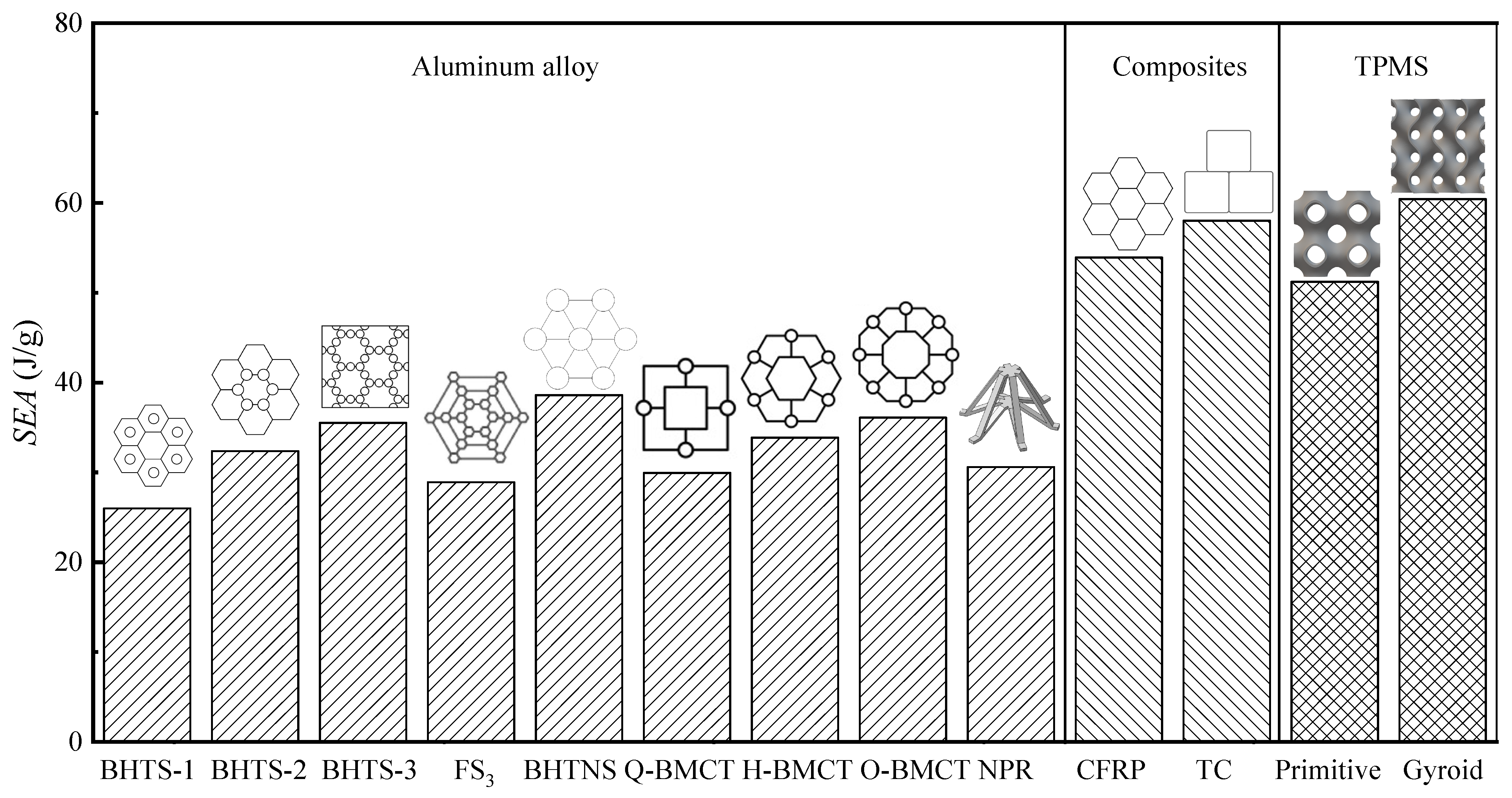
The results of this work were compared with the novelty energy absorbing boxes designed by scientific researchers in Figure 16.
Structures BHTS 1–2 [45], BHTS-3 [46], FS3 [47], BHTNS [48], Q, H, and O-BMCT [49] are biomimetic multi-cell tubes based on aluminum alloys, whereas NPR structure [50] is a novel three-dimensional double-arrow structure with negative Poisson’s ratio. The SEA values of the aluminum alloy tubes fluctuate around 30 J/g, which is clearly lower than that of CFRP [51] honeycomb boxes (53.9 J/g) and TC [52] triple-cell boxes (58.0 J/g). The SEA of energy absorbing boxes with porous, filled TPMS structures is 36.5% and 50.2% higher than that of the aluminum alloy energy absorbing boxes, approximately. The energy absorption capacity of an energy absorbing box filled with Primitive or Gyroid is comparable to composite structures of integrated biomimetic design or even slightly higher than them. This suggests that the Primitive and Gyroid samples, fabricated from FS271M, are promising candidates for improving crashworthiness.
4. Conclusions
In this paper, TPMS modeling and triangulation are realized based on MATLAB, and quasi-static compression tests are carried out on periodic porous TPMS structures printed by SLM. Subsequently, combined with the joint simulation of Hypermesh and Abaqus to realize the axial compression simulation of porous TPMS structure, the deformation mechanism, mechanical response, and energy absorption characteristics of different porous TPMS structures under axial quasi-static compressive loads are systematically analyzed. Finally, the Gyroid and Primitive structures with excellent mechanical properties are selected as the inner core to design the automotive energy-absorbing box. The boxes are printed via SLM. Combined with low-speed impact experiment and simulation, the deformation mechanism, impact resistance, and energy absorbing properties of crash boxes filled with porous TPMS structures were compared with those of the traditional thin-walled crash box. The key findings from this research are summarized below.
- Structural failure of the porous TPMS structure along the surface shear bands under axial quasi-static compressive loading conditions. Deformation is dominated by layered bending collapse, which stabilizes structural deformation while reducing peak loads.
- The load–displacement curves of the porous TPMS structures (Gyroid and Primitive) subjected to external loads fluctuate smoothly. The more prominent the shear deformation of the porous TPMS structure, the less the fluctuation degree of the platform section affected by the single load.
- The energy-absorbing box filled with porous TPMS structures is attributed to a particular deformation behavior. The failure form of layer-by-layer collapse provides it with high-quality energy absorption capacity, and its peak load and load fluctuation are significantly reduced compared with traditional thin-walled energy-absorbing boxes. On the premise of ensuring lightweight and energy absorption requirements, a new solution is provided for solving the problems of excessive peak load and unstable load fluctuation of traditional thin-walled energy-absorbing boxes.
- Comprehensive analysis shows that the porous TPMS structure has the advantages of eliminating stress concentration and improving mechanical strength. Automobile energy absorbing boxes filled with porous TPMS structures have excellent impact resistance and energy absorption characteristics compared with traditional thin-walled energy-absorbing boxes. The porous TPMS structure is an ideal candidate for lightweight multifunctional structures.
- The research is based on SLM to realize the lightweight design of automotive energy-absorbing boxes and to provide the basis for the selection of other parts. Additional research should be carried out on the influence of the parameters of additive manufacturing and the selection of raw materials on the mechanical behavior of porous TPMS structures. Through the matching of different additive manufacturing technologies and excellent raw materials, combined with the topological optimization of porous TPMS structure, the integrated design of goal–material–structure–function can be achieved.
Author Contributions
Conceptualization, X.Z. (Xuejin Zhao) and Z.L.; formal analysis, Z.L. and X.Z. (Xiaoyu Zhao); methodology, X.Z. (Xuejin Zhao); software, X.Z. (Xuejin Zhao); supervision, Z.L.; validation, X.Z. (Xuejin Zhao); visualization, X.Z. (Xiaoyu Zhao); writing—original draft, Z.L. and Y.Z.; writing—review and editing, Z.L. and Y.Z. All authors have read and agreed to the published version of the manuscript.
Funding
This research was funded by the National Natural Science Foundation of China (grant number: 51705534) and the Natural Science Foundation of Shandong Province (grant number: ZR2022MF291).
Data Availability Statement
The data presented in this study are available upon request from the corresponding author.
Conflicts of Interest
The authors declare no conflicts of interest.
References
- Du, Y.; Zhao, Y.; Li, H. Subsidy policy and carbon quota mechanism of the Chinese vehicle industry. Transp. Res. Part D Transp. Environ. 2023, 121, 103806. [Google Scholar] [CrossRef]
- Zhang, W.; Xu, J. Advanced lightweight materials for Automobiles: A review. Mater. Des. 2022, 221, 110994. [Google Scholar] [CrossRef]
- Lv, X.; Xiao, Z.; Fang, J.; Li, Q.; Lei, F.; Sun, G. On safety design of vehicle for protection of vulnerable road users: A review. Thin-Walled Struct. 2023, 182, 109990. [Google Scholar] [CrossRef]
- Yoo, S.H.; Chang, S.H.; Sutcliffe, M.P.F. Compressive characteristics of foam-filled composite egg-box sandwich panels as energy absorbing structures. Compos. Part A Appl. Sci. Manuf. 2010, 41, 427–434. [Google Scholar] [CrossRef]
- Liu, W.; Zhang, Y.; Guo, Z.; Li, D.; Zhao, S.; Xie, W. Analyzing in-plane mechanics of a novel honeycomb structure with zero Poisson’s ratio. Thin-Walled Struct. 2023, 192, 111134. [Google Scholar] [CrossRef]
- Montgomery-Liljeroth, E.; Schievano, S.; Burriesci, G. Elastic properties of 2D auxetic honeycomb structures- a review. Appl. Mater. Today 2023, 30, 101722. [Google Scholar] [CrossRef]
- Peng, X.; Liu, G.; Li, J.; Wu, H.; Jia, W.; Jiang, S. Compression property and energy absorption capacity of 4D-printed deformable honeycomb structure. Compos. Struct. 2023, 325, 117591. [Google Scholar] [CrossRef]
- Shen, X.; Hu, Q.; Zhu, D.; Qi, S.; Huang, C.; Yuan, M.; Qian, X.; Guo, R. Dynamic mechanical response prediction model of honeycomb structure based on machine learning method and finite element method. Int. J. Impact Eng. 2024, 184, 104825. [Google Scholar] [CrossRef]
- Jongpradist, P.; Tongthong, S.; Kongwat, S.; Ruangjirakit, K.; Thongchom, C.; Hasegawa, H. Optimizing functionally graded hexagonal crash boxes with honeycomb filler for enhanced crashworthiness. Structures 2024, 59, 105775. [Google Scholar] [CrossRef]
- Wei, W.; Zhang, F.; Xing, Y.; Wang, H.; Liu, R. Research on Mechanical Properties of Origami Aluminum Honeycomb for Automobile Energy Absorbing Box. Materials 2023, 16, 141. [Google Scholar] [CrossRef]
- Li, X.; Yu, W.; Liu, J.; Zhu, X.; Wang, H.; Sun, X.; Liu, J.; Yuan, H. A mechanics model of hard-magnetic soft rod with deformable cross-section under three-dimensional large deformation. Int. J. Solids Struct. 2023, 279, 112344. [Google Scholar] [CrossRef]
- Moosavian, H.; Tang, T. Statistical mechanics of coil–rod structure in biopolymer gels. J. Mech. Phys. Solids 2023, 175, 105272. [Google Scholar] [CrossRef]
- Browne, C.; Raghuwanshi, V.S.; Garnier, G.; Batchelor, W. Modulating the chiral nematic structure of cellulose nanocrystal suspensions with electrolytes. J. Colloid. Interface. Sci. 2023, 650, 1064–1072. [Google Scholar] [CrossRef] [PubMed]
- Li, X.; Cheng, S.; Wang, R.; Yan, Q.; Wang, B.; Sun, Y.; Yan, H.; Zhao, Q.; Xin, Y. Design of novel two-dimensional single-phase chiral phononic crystal assembly structures and study of bandgap mechanism. Results Phys. 2023, 48, 106431. [Google Scholar] [CrossRef]
- Xu, W.; Zhang, L.; Zhang, B.; Zhang, H.; Liu, Z.; Zhu, P. Crushing behavior of contact-aided AlSi10Mg sandwich structure based on chiral mechanical metamaterials. Int. J. Mech. Sci. 2023, 260, 108636. [Google Scholar] [CrossRef]
- Ma, X.; Zhang, N.; Chang, Y.; Tian, X. Analytical model of mechanical properties for a hierarchical lattice structure based on hierarchical body-centered cubic unit cell. Thin-Walled Struct. 2023, 193, 111217. [Google Scholar] [CrossRef]
- Deshpande, V.S.; Fleck, N.A.; Ashby, M.F. Effective properties of the octet-truss lattice material. J. Mech. Phys. Solids 2001, 49, 1747–1769. [Google Scholar] [CrossRef]
- Kooistra, G. Compressive behavior of age hardenable tetrahedral lattice truss structures made from aluminium. Acta Mater. 2004, 52, 4229–4237. [Google Scholar] [CrossRef]
- Moongkhamklang, P.; Deshpande, V.S.; Wadley, H.N.G. The compressive and shear response of titanium matrix composite lattice structures. Acta Mater. 2010, 58, 2822–2835. [Google Scholar] [CrossRef]
- Sun, G.; Chen, D.; Zhu, G.; Li, Q. Lightweight hybrid materials and structures for energy absorption: A state-of-the-art review and outlook. Thin-Walled Struct. 2022, 172, 108760. [Google Scholar] [CrossRef]
- Li, N.; Xue, C.; Chen, S.; Aiyiti, W.; Khan, S.B.; Liang, J.; Zhou, J.; Lu, B. 3D Printing of Flexible Mechanical Metamaterials: Synergistic Design of Process and Geometric Parameters. Polymers 2023, 15, 4523. [Google Scholar] [CrossRef]
- Rico-Baeza, G.; Pérez-Soto, G.I.; Morales-Hernández, L.A.; Cuan-Urquizo, E.; Camarillo-Gómez, K.A. Additively Manufactured Foot Insoles Using Body-Centered Cubic (BCC) and Triply Periodic Minimal Surface (TPMS) Cellular Structures. Appl. Sci. 2023, 13, 12665. [Google Scholar] [CrossRef]
- Xue, C.; Li, N.; Chen, S.; Liang, J.; Aiyiti, W. The Laser Selective Sintering Controlled Forming of Flexible TPMS Structures. Materials 2023, 16, 7565. [Google Scholar] [CrossRef]
- Du Plessis, A.; Yadroitsava, I.; Yadroitsev, I.; le Roux, S.G.; Blaine, D.C. Numerical comparison of lattice unit cell designs for medical implants by additive manufacturing. Virtual Phys. Prototyp. 2018, 13, 266–281. [Google Scholar] [CrossRef]
- Zargarian, A.; Esfahanian, M.; Kadkhodapour, J.; Ziaei-Rad, S.; Zamani, D. On the Fatigue Behavior of Additive Manufactured Lattice Structures. Theor. Appl. Fract. Mech. 2019, 100, 225–232. [Google Scholar] [CrossRef]
- Wu, R.; Roberts, P.C.; Lyu, S.; Zheng, F.; Soutis, C.; Diver, C.; Zhou, D.; Li, L.; Deng, Z. Lightweight Self-Forming Super-Elastic Mechanical Metamaterials with Adaptive Stiffness. Adv. Funct. Mater. 2020, 31, 2008252. [Google Scholar] [CrossRef]
- Sychov, M.M.; Lebedev, L.A.; Dyachenko, S.V.; Nefedova, L.A. Mechanical properties of energy-absorbing structures with triply periodic minimal surface topology. Acta Astronaut. 2018, 150, 81–84. [Google Scholar] [CrossRef]
- Berger, J.B.; Wadley, H.N.G.; Mcmeeking, R.M. Mechanical metamaterials at the theoretical limit of isotropic elastic stiffness. Nature 2017, 543, 533. [Google Scholar] [CrossRef]
- Lal Lazar, P.J.; Subramanian, J.; Natarajan, E.; Markandan, K.; Ramesh, S. Anisotropic structure-property relations of FDM printed short glass fiber reinforced polyamide TPMS structures under quasi-static compression. J. Mater. Res. Technol. 2023, 24, 9562–9579. [Google Scholar] [CrossRef]
- Ge, J.; Huang, Q.; Wang, Y.; Zhang, C.; Liu, Q.; Lu, Z.; Yin, S. Microstructural optimization and mechanical enhancement of SLM Ti6Al4V TPMS scaffolds through vacuum annealing treatment. J. Alloys Compd. 2023, 934, 167524. [Google Scholar] [CrossRef]
- Leary, M.; Mazur, M.; Elambasseril, J.; Mcmillan, M.; Chirent, T.; Sun, Y.; Qian, M.; Easton, M.; Brandt, M. Selective laser melting (SLM) of AlSi12Mg lattice structures. Mater. Des. 2016, 98, 344–357. [Google Scholar] [CrossRef]
- Giorleo, L.; Bonaventi, M. Casting of complex structures in aluminum using gypsum molds produced via binder jetting. Rapid Prototyp. J. 2021, 27, 13–23. [Google Scholar] [CrossRef]
- Jonsson, S.; Kajberg, J. Evaluation of Crashworthiness Using High-Speed Imaging, 3D Digital Image Correlation, and Finite Element Analysis. Metals 2023, 13, 1834. [Google Scholar] [CrossRef]
- Doroszko, M. Numerical Investigation of the Defects Effect in Additive Manufactured Ti-6Al-4V Struts on Deformation Behavior Based on Microtomographic Images. Materials 2022, 15, 4807. [Google Scholar] [CrossRef]
- Guillou, E.; King, A.; Perrin, J.; Proudhon, H.; Weitkamp, T.; Shah, D.U.; Beigbeder, A.; Ouagne, P.; Bourmaud, A. Impact of flax fibre micro-structural features on composite damage observed through micro-CT characterisation. Compos. Part A Appl. Sci. Manuf. 2024, 181, 108118. [Google Scholar] [CrossRef]
- Al Ketan, O.; Abu Al Rub, R.K. MSLattice: A free software for generating uniform and graded lattices based on triply periodic minimal surfaces. Mater. Des. Process. Commun. 2021, 3, e205. [Google Scholar] [CrossRef]
- Han, D.; Ren, X.; Luo, C.; Zhang, Y.; Zhang, X.Y.; Zhang, X.G.; Jiang, W.; Hao, J.; Xie, Y.M. Experimental and computational investigations of novel 3D printed square tubular lattice metamaterials with negative Poisson’s ratio. Addit. Manuf. 2022, 55, 102789. [Google Scholar] [CrossRef]
- Nagarajan, B.; Hu, Z.; Song, X.; Zhai, W.; Wei, J. Development of Micro Selective Laser Melting: The State of the Art and Future Perspectives. Engineering 2019, 5, 702–720. [Google Scholar] [CrossRef]
- ISO 13314:2011; Mechanical Testing of Metals—Ductility Test_Ing—Compression Test for Porous and Cellular Metals. ISO: Geneva, Switzerland, 2011.
- Fan, W.; Xie, R.; Davidson, M.; Yin, H.; Lai, K.; Wu, Q. Crashworthiness and energy absorption of UHPFRC-steel composite sandwich structures under impact loading. Compos. Struct. 2023, 311, 116813. [Google Scholar] [CrossRef]
- Wu, B.; Chen, Q.; Liu, F.; Chen, M.; Lu, Y.; Jiang, D.; Yi, Y. Study on Dynamic Mechanics of Node-Enhanced Graded Lattice Structure and Application Optimization in Automobile Energy Absorbing Box. Materials 2023, 16, 6893. [Google Scholar] [CrossRef]
- Xie, C.; Wang, D.; Zong, L.; Wang, S.; Kong, D. Multi-objective crashworthiness optimization of energy-absorbing box with gradient lattice structure. Appl. Math. Model. 2023, 121, 304–320. [Google Scholar] [CrossRef]
- Djamaluddin, F. Optimization of foam-filled crash-box under axial loading for pure electric vehicle. Results Mater. 2024, 21, 100505. [Google Scholar] [CrossRef]
- Yunus Nasution, A.; Ruzaimi Mat Rejab, M.; Parlaungan Siregar, J.; Ma, Q. Combination of frustra shapes with cross sections and trigger circles for crash box design to absorb energy. Mater. Today Proc. 2023. [Google Scholar] [CrossRef]
- Xiang, J.; Du, J. Energy absorption characteristics of bio-inspired honeycomb structure under axial impact loading. Mater. Sci. Eng. A 2017, 696, 283–289. [Google Scholar] [CrossRef]
- Hao, P.; Du, J. Energy absorption characteristics of bio-inspired honeycomb column thin-walled structure under impact loading. J. Mech. Behav. Biomed. Mater. 2018, 79, 301–308. [Google Scholar] [CrossRef]
- Zhang, Y.; Wang, J.; Wang, C.; Zeng, Y.; Chen, T. Crashworthiness of bionic fractal hierarchical structures. Mater. Des. 2018, 158, 147–159. [Google Scholar] [CrossRef]
- Hu, D.; Wang, Y.; Song, B.; Dang, L.; Zhang, Z. Energy-absorption characteristics of a bionic honeycomb tubular nested structure inspired by bamboo under axial crushing. Compos. Part B Eng. 2019, 162, 21–32. [Google Scholar] [CrossRef]
- Zhang, L.; Bai, Z.; Bai, F. Crashworthiness design for bio-inspired multi-cell tubes with quadrilateral, hexagonal and octagonal sections. Thin-Walled Struct. 2018, 122, 42–51. [Google Scholar] [CrossRef]
- Alia, R.A.; Al-Ali, O.; Kumar, S.; Cantwell, W.J. The energy-absorbing characteristics of carbon fiber-reinforced epoxy honeycomb structures. J. Compos. Mater. 2019, 53, 1145–1157. [Google Scholar] [CrossRef]
- Liu, Q.; Ma, J.; He, Z.; Hu, Z.; Hui, D. Energy absorption of bio-inspired multi-cell CFRP and aluminum square tubes. Compos. Part B Eng. 2017, 121, 134–144. [Google Scholar] [CrossRef]
- Song, Z.; Liang, H.; Ding, H.; Ma, M. Structure design and mechanical properties of a novel anti-collision system with negative Poisson’s ratio core. Int. J. Mech. Sci. 2023, 239, 107864. [Google Scholar] [CrossRef]
Figure 1.
The schematic diagram of triply periodic minimal surface (TPMS) unit morphology.
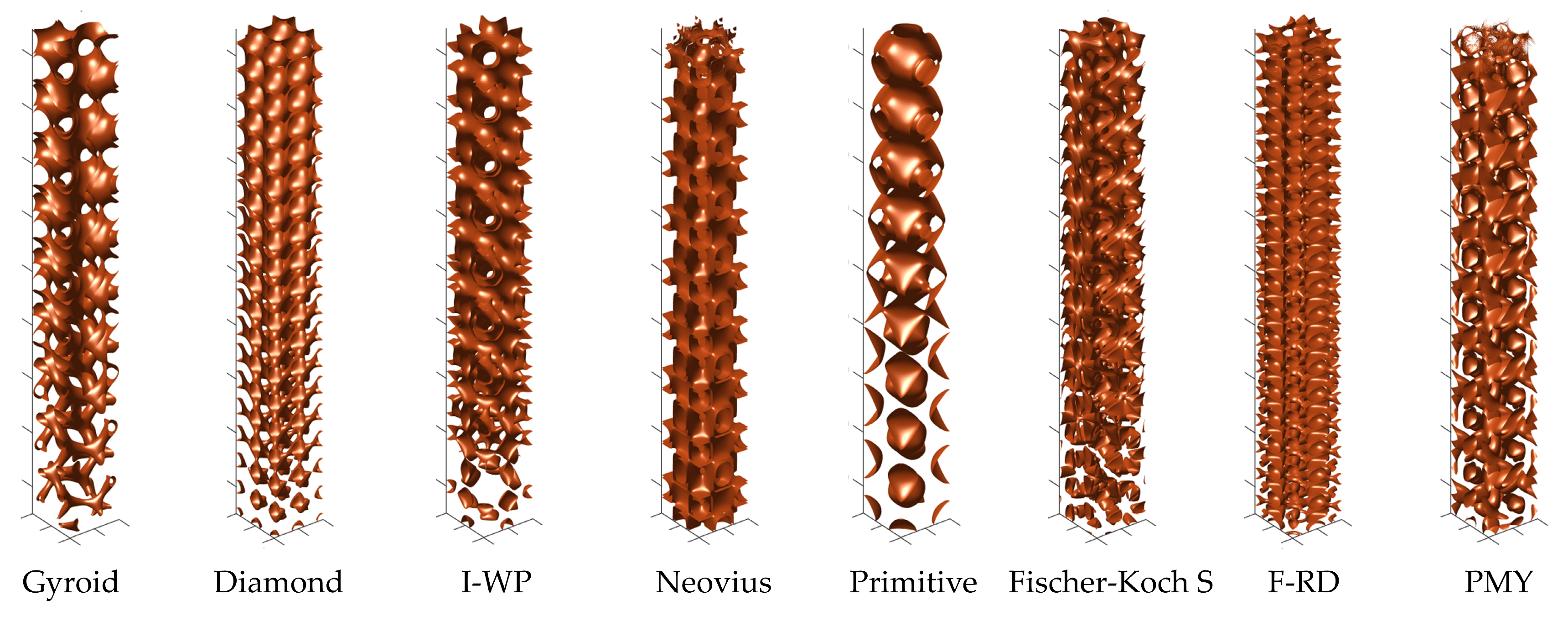
Figure 2.
The materialization of triply periodic minimal surface (TPMS) element based on the Delaunay triangulation principle and 3D-printing TPMS unit model of 30% porosity.
Figure 2.
The materialization of triply periodic minimal surface (TPMS) element based on the Delaunay triangulation principle and 3D-printing TPMS unit model of 30% porosity.


Figure 3.
SLM (selective laser melting) 3D-printing equipment.
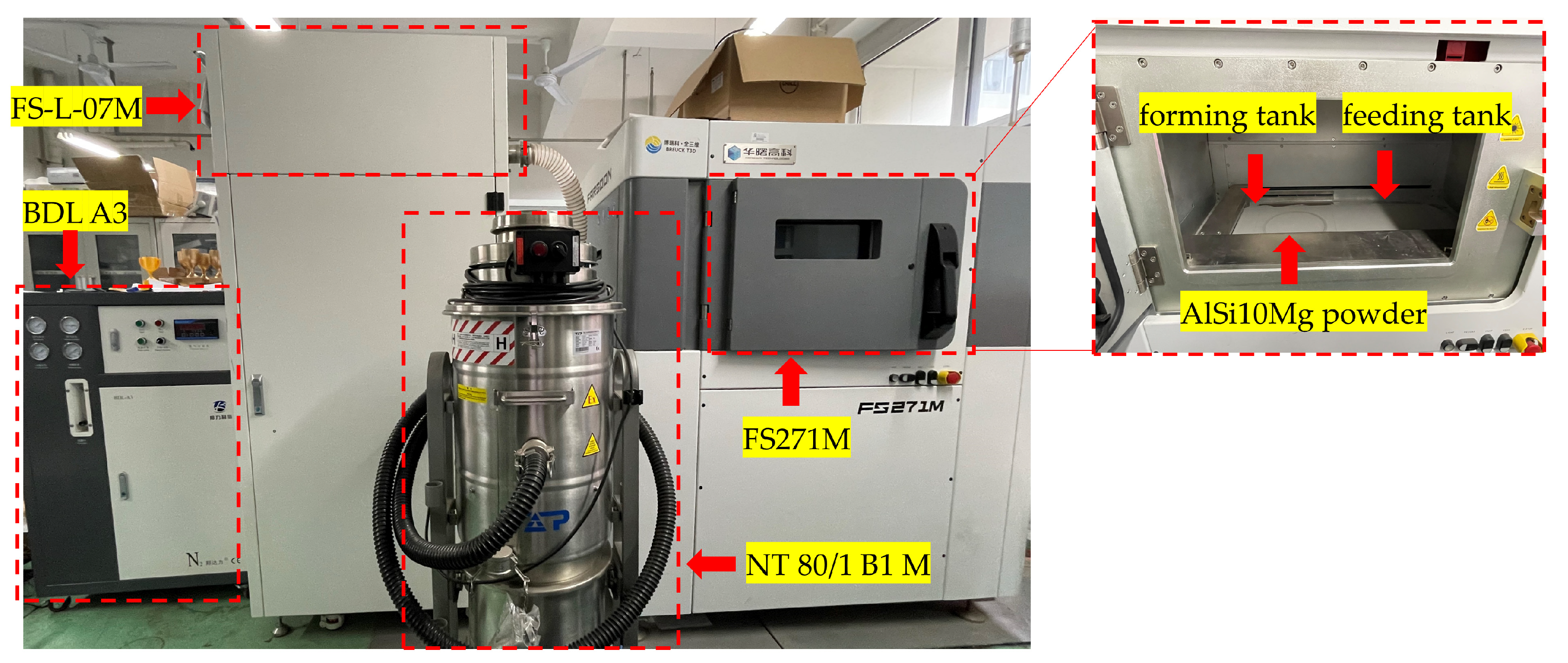
Figure 4.
The schematic diagram of the preparation of the porous triply periodic minimal surface (TPMS) structure compression samples by selective laser melting (SLM) technology.
Figure 4.
The schematic diagram of the preparation of the porous triply periodic minimal surface (TPMS) structure compression samples by selective laser melting (SLM) technology.

Figure 5.
Test setup for determining the mechanical and energy-absorbing properties.
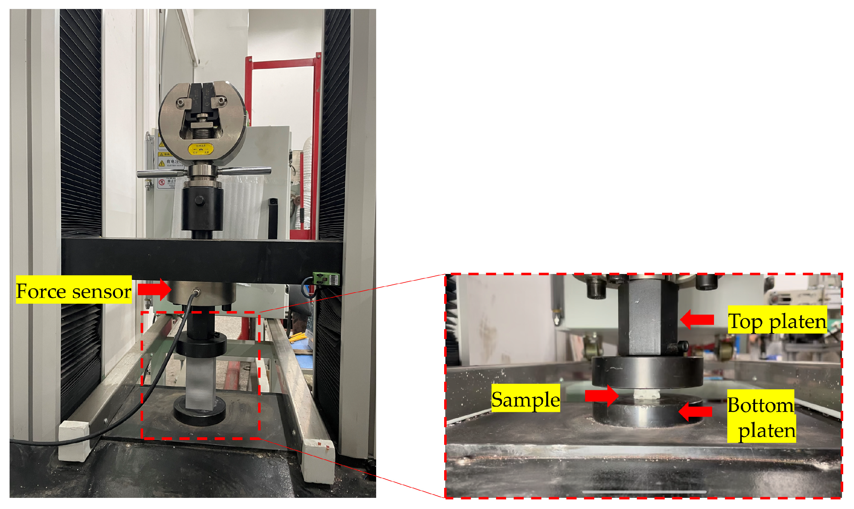
Figure 6.
The quasi-static compression finite element analysis model of the porous structure.
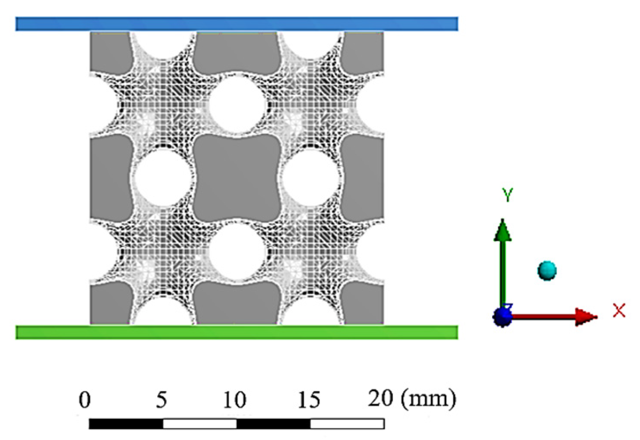
Figure 7.
Schematic diagram of the design process of the energy-absorbing box filled with porous triply periodic minimal surface (TPMS) structures (Gyroid or Primitive).
Figure 7.
Schematic diagram of the design process of the energy-absorbing box filled with porous triply periodic minimal surface (TPMS) structures (Gyroid or Primitive).

Figure 8.
The selective laser melting (SLM) printing products of the automobile energy-absorbing boxes with porous triply periodic minimal surface (TPMS) structure filled.
Figure 8.
The selective laser melting (SLM) printing products of the automobile energy-absorbing boxes with porous triply periodic minimal surface (TPMS) structure filled.

Figure 9.
Experimental characteristics of porous triply periodic minimal surface (TPMS) structure samples under different compression displacements of 1 mm, 4 mm, 7 mm, 10 mm, and the von Mises stress cloud images verify the compression test results.
Figure 9.
Experimental characteristics of porous triply periodic minimal surface (TPMS) structure samples under different compression displacements of 1 mm, 4 mm, 7 mm, 10 mm, and the von Mises stress cloud images verify the compression test results.
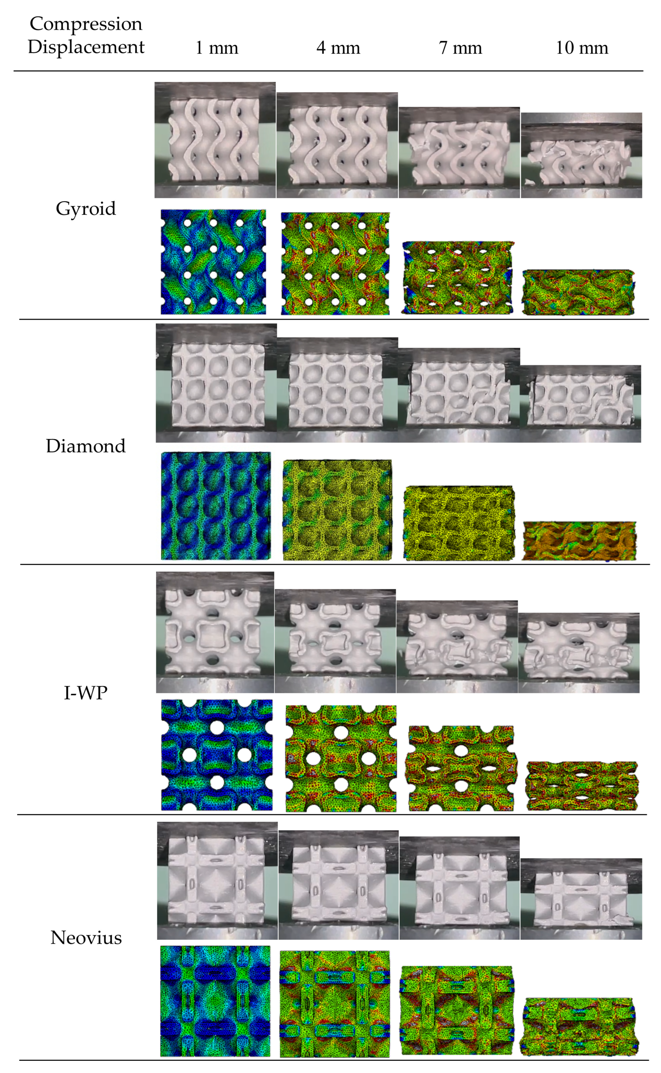
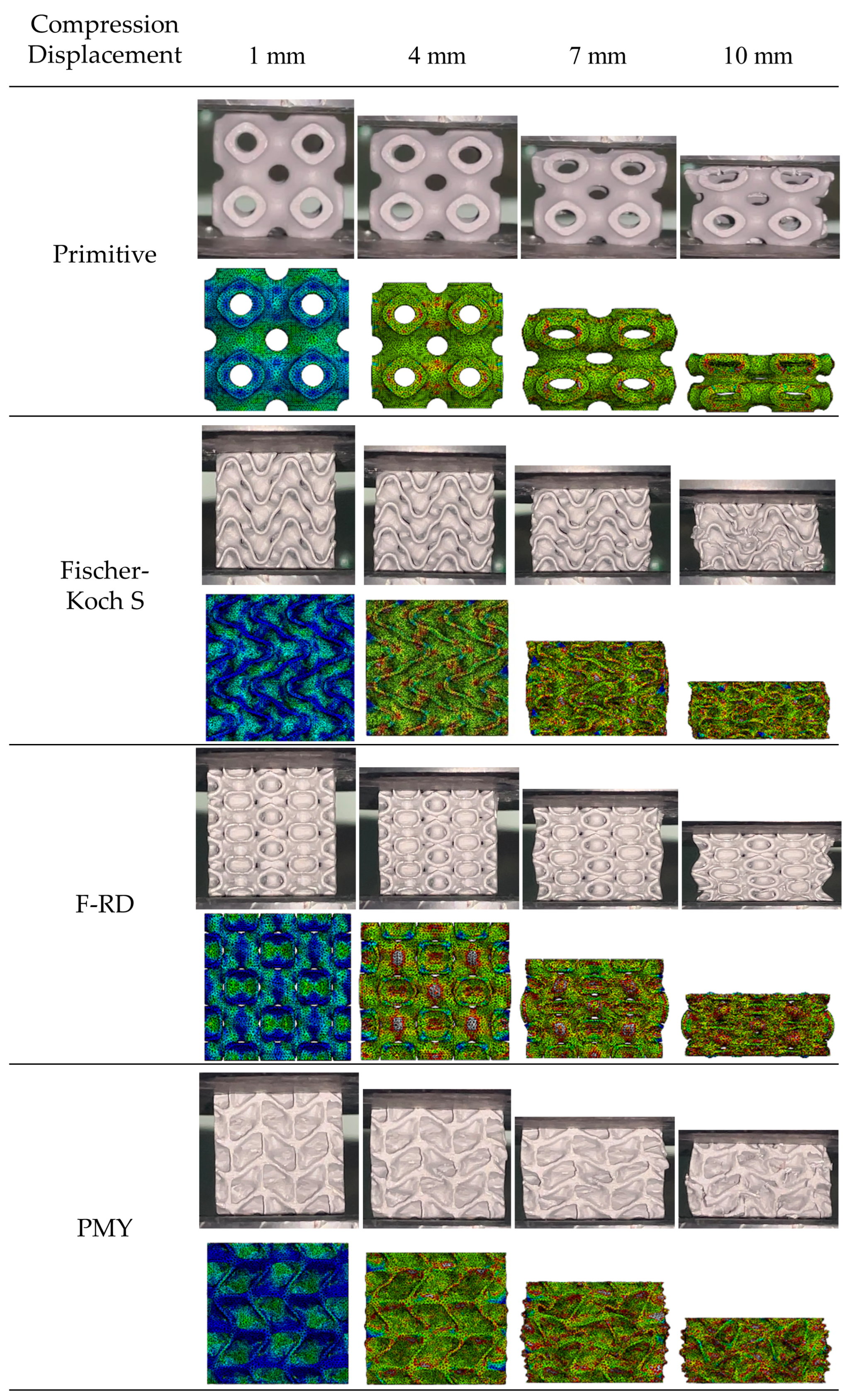
Figure 10.
The post-processing results of quasi-static compression experiments. (a) The load-displacement curves based on finite element simulation results. (b) The multi-component waterfall diagram obtained from three sets of compression tests and finite element simulation results.
Figure 10.
The post-processing results of quasi-static compression experiments. (a) The load-displacement curves based on finite element simulation results. (b) The multi-component waterfall diagram obtained from three sets of compression tests and finite element simulation results.

Figure 11.
Energy absorption efficiency curves of different porous triply periodic minimal surface (TPMS) structures.
Figure 11.
Energy absorption efficiency curves of different porous triply periodic minimal surface (TPMS) structures.
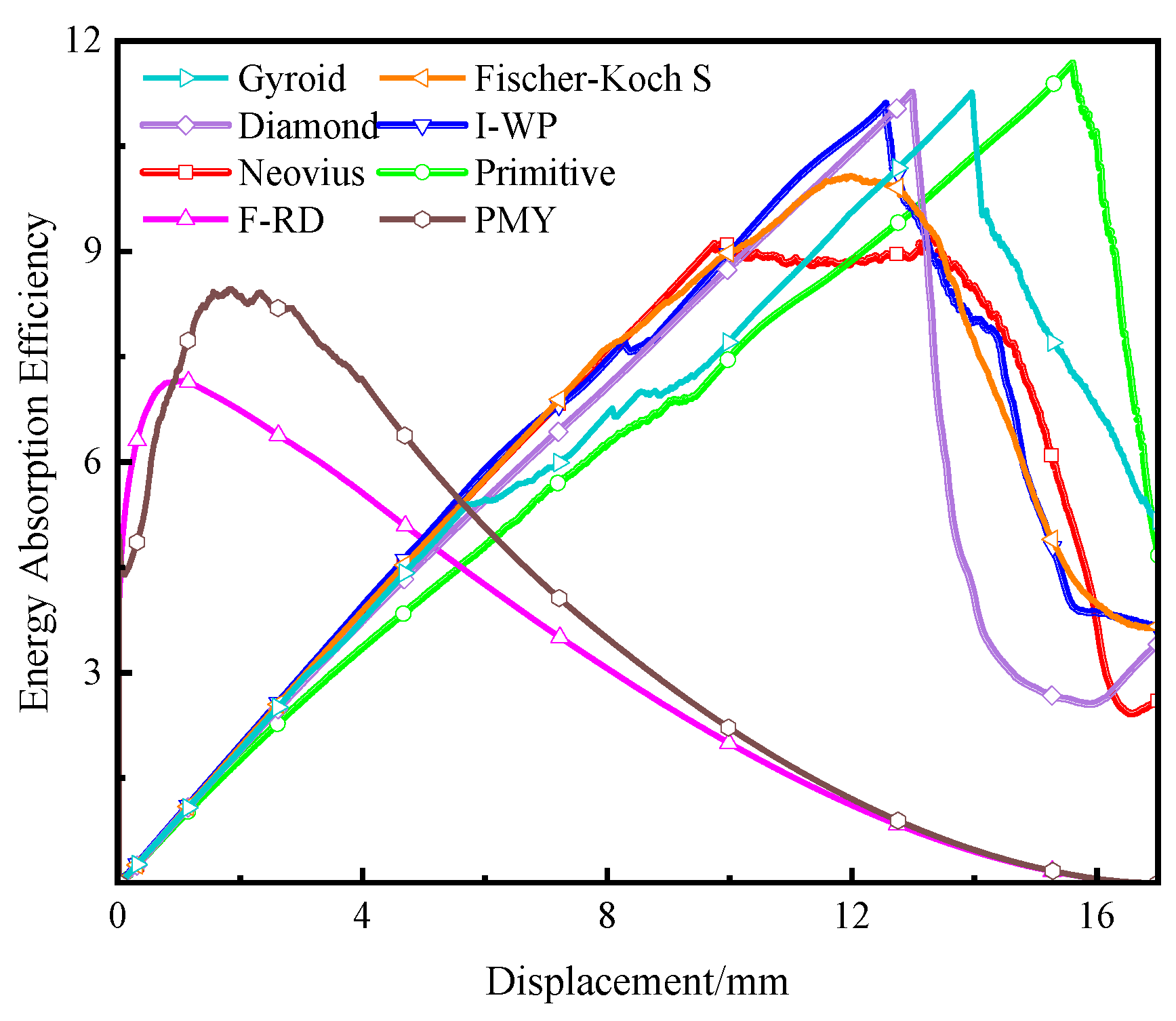
Figure 12.
Experimental characteristics of the automobile energy-absorbing box filled with porous triply periodic minimal surface (TPMS) structure under 4.4 m/s speed impact, and the von Mises stress cloud diagram of three energy-absorbing boxes under different collision moments of 0 ms, 3 ms, 6 ms, 9 ms, and 12 ms.
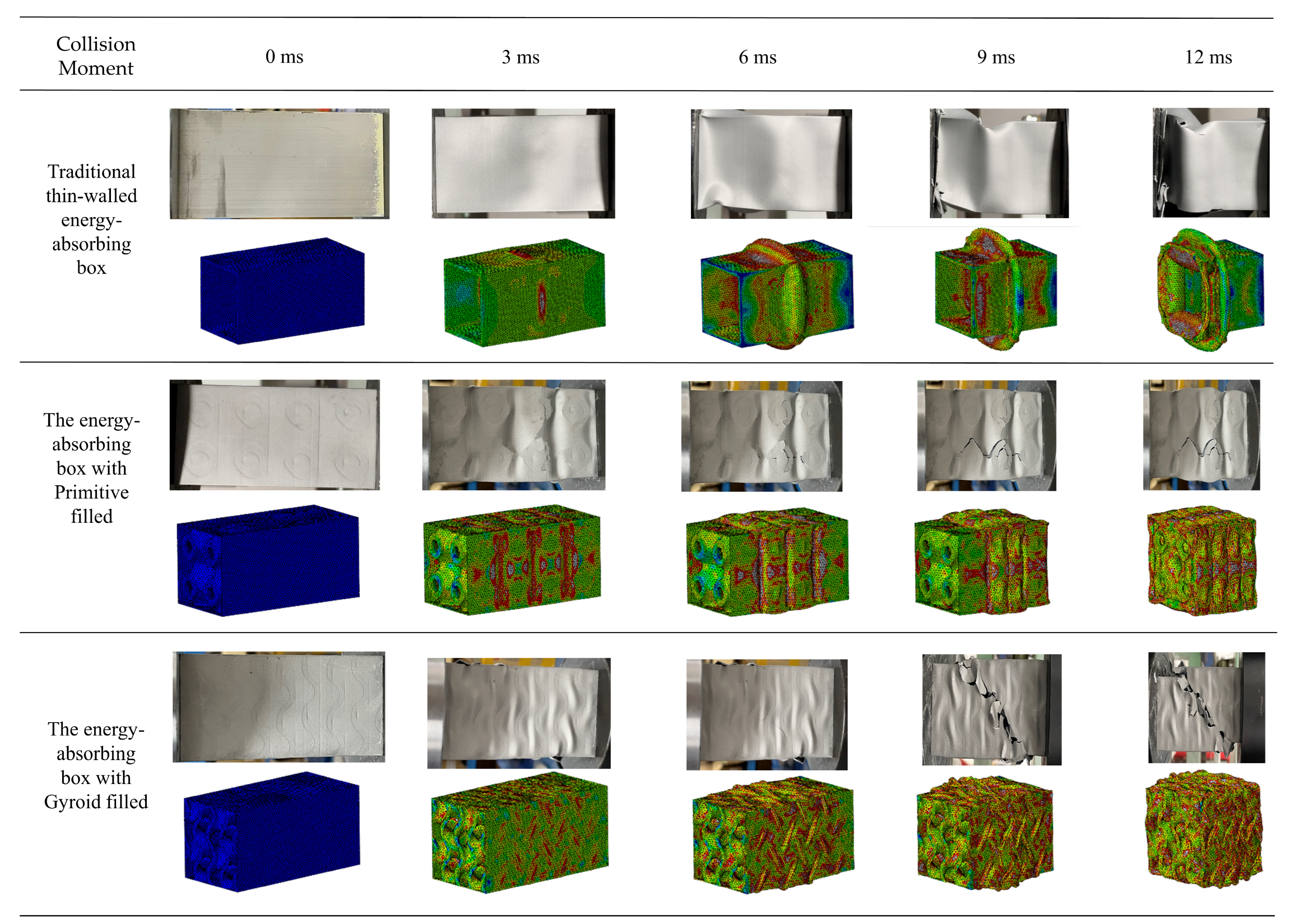
Figure 13.
Internal shape damage of three energy-absorbing boxes in the phase of collision plateau.
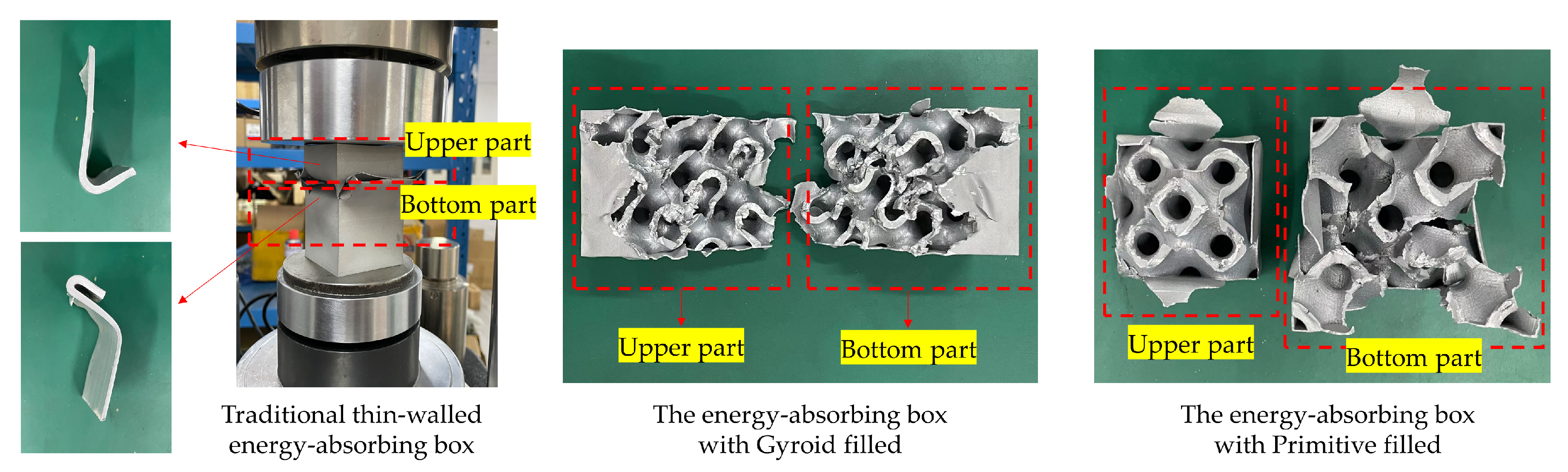
Figure 14.
The post-processing results of low-speed impact experiments. (a) The load–displacement curves drawn based on finite element simulation results (the spherical point: the first breakage judgment point of different energy-absorbing boxes). (b) The multi-component waterfall diagram obtained from three sets of low-speed impact tests and finite element simulation results.

Figure 15.
Comparison of energy-absorbing indexes of energy-absorbing boxes.

Figure 16.
The comparison between specific energy absorption values of porous triply periodic minimal surface (TPMS) structures, bio-inspired structures, and other composite structures.
Figure 16.
The comparison between specific energy absorption values of porous triply periodic minimal surface (TPMS) structures, bio-inspired structures, and other composite structures.

Table 1.
TPMS (triply periodic minimal surface) units and their implicit function expressions.
| TPMS | Implicit Function Expression |
|---|---|
| Gyroid | |
| Diamond | |
| I-WP | |
| Neovius | |
| Primitive | |
| Fischer-Koch S | |
| F-RD | |
| PMY |
where , , , L is the period of change of the implicit surface, and t is the distance constant of the implicit surface.
Table 2.
Mechanical properties of AlSi10Mg.
| Property | Magnitude |
|---|---|
| Density (g/cm3) | 2.71 |
| Young’s modulus (GPa) | 70 |
| Yield strength (MPa) | 284 |
| Poisson’s ratio | 0.33 |
Table 3.
Quality characterization of printed samples with uniform and gradient structures.
| Type | Weight (g) | Dimension (X × Y × Z mm) | |
|---|---|---|---|
| Gyroid | Sample 1 | 7.00 | 19.92 × 20.02 × 19.52 |
| Sample 2 | 7.03 | 19.92 × 20.00 × 19.82 | |
| Sample 3 | 7.01 | 20.02 × 19.88 × 19.62 | |
| Diamond | Sample 1 | 7.83 | 20.18 × 20.20 × 20.10 |
| Sample 2 | 7.63 | 20.12 × 20.18 × 20.16 | |
| Sample 3 | 7.47 | 20.20 × 20.00 × 20.12 | |
| I-WP | Sample 1 | 7.58 | 19.82 × 20.14 × 20.26 |
| Sample 2 | 7.58 | 20.02 × 20.12 × 20.20 | |
| Sample 3 | 7.22 | 20.12 × 19.94 × 20.18 | |
| Neovius | Sample 1 | 8.74 | 20.20 × 19.92 × 20.10 |
| Sample 2 | 8.66 | 20.12 × 19.98 × 20.08 | |
| Sample 3 | 8.66 | 20.10 × 19.94 × 20.12 | |
| Primitive | Sample 1 | 6.88 | 19.88 × 19.92 × 20.00 |
| Sample 2 | 6.76 | 19.92 × 19.42 × 19.92 | |
| Sample 3 | 6.66 | 19.92 × 19.62 × 19.94 | |
| Fischer-Koch S | Sample 1 | 8.46 | 19.72 × 19.72 × 20.02 |
| Sample 2 | 8.50 | 19.62 × 19.92 × 20.00 | |
| Sample 3 | 8.60 | 19.62 × 20.02 × 20.04 | |
| F-RD | Sample 1 | 9.07 | 20.09 × 20.12 × 19.92 |
| Sample 2 | 9.43 | 20.20 × 20.20 × 19.92 | |
| Sample 3 | 9.27 | 20.13 × 20.20 × 19.96 | |
| PMY | Sample 1 | 10.13 | 19.41 × 20.02 × 19.82 |
| Sample 2 | 10.18 | 19.62 × 20.00 × 19.92 | |
| Sample 3 | 10.33 | 19.42 × 20.40 × 20.00 | |
Table 4.
Quality characterization of printed boxes with porous triply periodic minimal surface (TPMS) structures filled.
Table 4.
Quality characterization of printed boxes with porous triply periodic minimal surface (TPMS) structures filled.
| Type of Automobile Energy-Absorbing Box | Weight (g) | Dimension (X × Y × Z mm) | |
|---|---|---|---|
| Traditional thin-walled box | Sample 1 | 150.83 | 49.82 × 50.12 × 99.50 |
| Sample 2 | 151.03 | 49.88 × 50.38 × 99.52 | |
| Sample 3 | 151.01 | 49.92 × 50.34 × 99.58 | |
| Gyroid filled box | Sample 1 | 228.88 | 50.01 × 50.02 × 99.62 |
| Sample 2 | 227.60 | 50.08 × 50.02 × 99.40 | |
| Sample 3 | 227.82 | 50.02 × 50.04 × 99.48 | |
| Primitive filled box | Sample 1 | 228.29 | 50.01 × 50.02 × 99.58 |
| Sample 2 | 228.36 | 50.08 × 50.08 × 99.60 | |
| Sample 3 | 228.33 | 50.02 × 50.04 × 99.60 | |
Table 5.
Comparison of compression energy absorption indexes of porous triply periodic minimal surface (TPMS) structure.
Table 5.
Comparison of compression energy absorption indexes of porous triply periodic minimal surface (TPMS) structure.
| TPMS | f (%) | m (g) | Sef (mm) | ESR (%) | Fm (kN) | SEA (J/g) |
|---|---|---|---|---|---|---|
| Gyroid | 11.27 | 7.013 | 11.88 | 59.40 | 18.38 | 31.14 |
| Diamond | 11.10 | 7.643 | 11.61 | 58.05 | 17.58 | 26.84 |
| I-WP | 10.08 | 7.460 | 10.56 | 52.80 | 17.51 | 24.79 |
| Neovius | 9.19 | 8.687 | 10.03 | 50.15 | 17.03 | 19.66 |
| Primitive | 11.68 | 6.767 | 12.28 | 61.40 | 16.09 | 29.20 |
| Fischer-Koch S | 9.61 | 8.520 | 9.99 | 49.95 | 13.58 | 15.92 |
| F-RD | 7.16 | 9.257 | 3.38 | 16.90 | 22.89 | 8.36 |
| PMY | 8.40 | 10.213 | 2.82 | 14.10 | 24.59 | 6.79 |
Disclaimer/Publisher’s Note: The statements, opinions and data contained in all publications are solely those of the individual author(s) and contributor(s) and not of MDPI and/or the editor(s). MDPI and/or the editor(s) disclaim responsibility for any injury to people or property resulting from any ideas, methods, instructions or products referred to in the content. |
© 2024 by the authors. Licensee MDPI, Basel, Switzerland. This article is an open access article distributed under the terms and conditions of the Creative Commons Attribution (CC BY) license (https://creativecommons.org/licenses/by/4.0/).
Share and Cite
MDPI and ACS Style
Zhao, X.; Li, Z.; Zou, Y.; Zhao, X. Compressive Characteristics and Energy Absorption Capacity of Automobile Energy-Absorbing Box with Filled Porous TPMS Structures. Appl. Sci. 2024, 14, 3790. https://doi.org/10.3390/app14093790
AMA Style
Zhao X, Li Z, Zou Y, Zhao X. Compressive Characteristics and Energy Absorption Capacity of Automobile Energy-Absorbing Box with Filled Porous TPMS Structures. Applied Sciences. 2024; 14(9):3790. https://doi.org/10.3390/app14093790
Chicago/Turabian StyleZhao, Xuejin, Zhenzong Li, Yupeng Zou, and Xiaoyu Zhao. 2024. "Compressive Characteristics and Energy Absorption Capacity of Automobile Energy-Absorbing Box with Filled Porous TPMS Structures" Applied Sciences 14, no. 9: 3790. https://doi.org/10.3390/app14093790
Note that from the first issue of 2016, this journal uses article numbers instead of page numbers. See further details here.