Article

Enhancing Furniture Manufacturing with 3D Scanning

1
Department of Mechanical Design, Faculty of Mechanical Engineering, University of Sarajevo, 71000 Sarajevo, Bosnia and Herzegovina
2
Institute of Machine Design, Faculty of Mechanical Engineering, Poznań University of Technology, 60-965 Poznań, Poland
3
Protodeves, 71000 Sarajevo, Bosnia and Herzegovina
4
Department of Physics and Mathematics, Faculty of Mechanical Engineering, University of Sarajevo, 71000 Sarajevo, Bosnia and Herzegovina
5
Department of Vehicle Engineering, Faculty of Mechanical Engineering, University of Sarajevo, 71000 Sarajevo, Bosnia and Herzegovina
6
Department of Woodworking and Fundamentals of Machine Design, Faculty of Forestry and Wood Technology, Poznań University of Life Sciences, 60-637 Poznań, Poland
*
Author to whom correspondence should be addressed.
Appl. Sci. 2024, 14(10), 4112; https://doi.org/10.3390/app14104112
Submission received: 8 April 2024 / Revised: 5 May 2024 / Accepted: 7 May 2024 / Published: 12 May 2024
(This article belongs to the Section Robotics and Automation)

Abstract

:
Product design and manufacturing leverage 3D scanning for various applications. This study aims to investigate the effectiveness of 3D scanning in furniture production by surveying the literature and showcasing four real-world case studies. The literature review reveals that 3D data acquired from real-world objects have applications in research, rapid prototyping, restoration, and preservation of antique furniture, optimizing CNC machining processes, and measuring furniture components for quality control. The case study descriptions demonstrated the circumstances, rationale, and methodology for 3D scanning. All the case studies analyzed stem from the collaboration between the Laboratory for Product Development and Design at the Faculty of Mechanical Engineering at the University of Sarajevo and various furniture production enterprises from Bosnia and Herzegovina. The conclusions highlight that 3D scanning in the furniture sector is advantageous for developing computer-aided design models from early-stage design prototypes, validating the dimensional accuracy of manufactured components by comparing with CAD models, safeguarding and reconstructing vintage furniture, and remanufacturing formerly produced goods that lack complete technical records (reverse engineering).

1. Introduction

The 3D scanning technology emerged in the 1960s [1]. However, its initial adoption was limited due to high hardware costs, low-quality scans, and difficulties processing large files. Today, 3D scanning has significantly advanced, finding applications from science and industry to creating digital characters for video games and movies and even archaeological and cultural heritage preservation through digitalization.
In the industry, 3D scanning is a tool for product design and development, manufacturing processes, and quality control. Its applications extend even further, providing valuable information on deformation, displacement, and movement analysis [2,3,4,5].
In the furniture industry, constantly creating products with complex shapes and forms presents a challenge for engineers, especially when dealing with prototypes of designer concepts [6]. The prototyping, from concept to final product, often involves multiple iterations due to difficulties in translating the designer’s vision into a physical form [7,8]. Three-dimensional scanning offers a significant improvement. After the designer creates a full-size, hand-crafted concept design, engineers can use 3D scanning technology to capture a digital copy. This digital model can be used to create a CAD model for future manufacturing [9]. There is a research gap in knowledge about the usefulness of 3D scanning in all stages of furniture production.
This study employs a two-fold approach to evaluate the effectiveness of 3D scanning in furniture production, including a literature survey and an analysis of four real-world case studies. All case studies stem from collaborations between the Laboratory for Product Development and Design at the Faculty of Mechanical Engineering, University of Sarajevo, and furniture manufacturing companies in Bosnia and Herzegovina.

2. An Up-To-Date Review of 3D Scanning in the Furniture Industry

Muminović et al. (2023) reviewed 3D scanning in Industry 4.0 applications [10]. Similar research is presented in the study by Javaid et al. [11]. These studies highlighted that 3D scanning is essential for manufacturers who need accurate dimensional inspection, virtual image analysis, and fast physical prototype manufacturing. Both studies discussed the potential of 3D scanning for the industrial sphere with the development of the workflow process of 3D scanners for industrial requirements. Javaid and co-authors identify and discuss sixteen main applications of 3D scanning from an industrial perspective but do not give specific furniture industry applications.
Three-dimensional scanning of furniture in scientific documents involves the use of technologies such as Terrestrial Laser Scanning (TLS) [12], custom trolley-based systems with laser scanners [13], and advanced methods such as reversible jump MCMC for structural element identification [14]. Additionally, repositories such as 3D-FUTURE provide richly annotated 3D furniture shapes for research purposes [15]. Recent advances include Mesh_CA, a method that combines neural networks and differentiable rendering for 3D object reconstruction without 3D supervision data [16]. These approaches enable the generation of accurate 3D furniture models, aiding in tasks such as furniture classification, structural element identification, and texture recovery for comprehensive research in areas like 3D modeling and object pose estimation.
Tsipotas and Spathopoulou [17], Elgewely [18], and Wang [19] described 3D scanning technology for restoring and protecting ancient furniture. These studies concluded that digitalization significantly enhances restoration quality when combined with modern manufacturing methods.
Three-dimensional scanning also has technological applications in the furniture industry. Sydor et al. [20] used 3D scanning to measure the instability of pinewood. In this study, 3D scanning was used as a metrology tool to evaluate the sustainability of wooden furniture elements for robotic montage. Bodi et al. [21] explore the relationship between cutting parameters, material properties, and part geometry in CNC machining and its impact on the quality of furniture parts. Two methods are presented to evaluate surface flatness and roughness, including manual and automated measurement techniques. The authors confirmed that 3D scanning helps automate manufacturing processes to improve the quality of components.
Curta et al. [22] present a digital close-range photogrammetry method as an inexpensive digitization technique used for abstract-shaped real objects, with the ultimate goal of being unique or mass production of the object using CNC machining. Although photogrammetry is a type of 3D scanning, it is generally not used in industrial applications. However, because of the growing need to digitize real-world objects for manufacturing in the shortest time and at a price as low as possible, such as ornamental objects or various components of furniture where the precision of the resulting 3D model is less demanding, it can be used for this purpose and only for large objects. Photogrammetric methods cannot be used to scan small and precise objects [23].
Valero et al. [12] conducted one of the first studies focusing on 3D scanning challenges for various complex surfaces of furniture using hand-held and stationary scanners. This is one of the first papers to research problems for 3D scanning different complex furniture surfaces using hand-held and stationary 3D scanners. Different materials were selected as experimental objects through the hand-held laser three-dimensional scanner mapping experiment, and three-dimensional scanner measurement technology was used to quickly transform the scanned image into one data point after another. Three-dimensional data were obtained by scanning the surface of complex furniture, and then the scan data were converted into a standard data format to simulate the model of the scanned object.
The research studies mentioned above are the only ones found on the furniture industry’s application and methodology of 3D scanning. As mentioned above, much of the research refers to general 3D scanning technology, its application, and its methods in other industries [5,24,25,26].

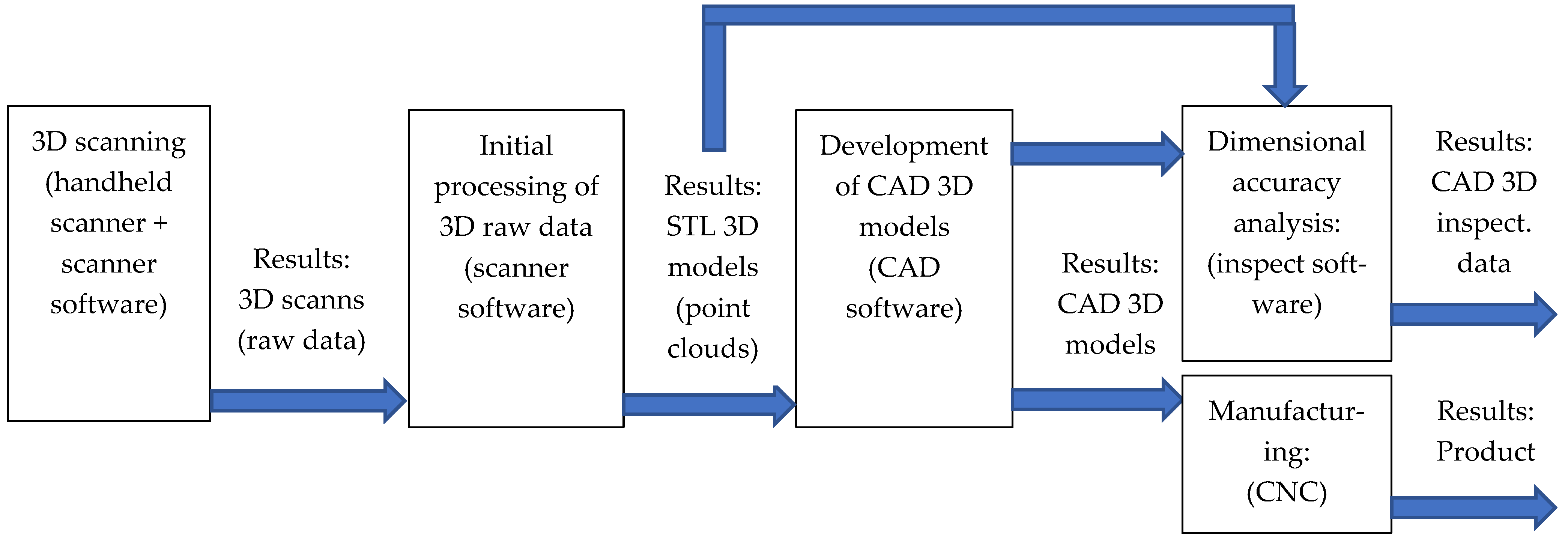
3. Experimental Setup and Methodology

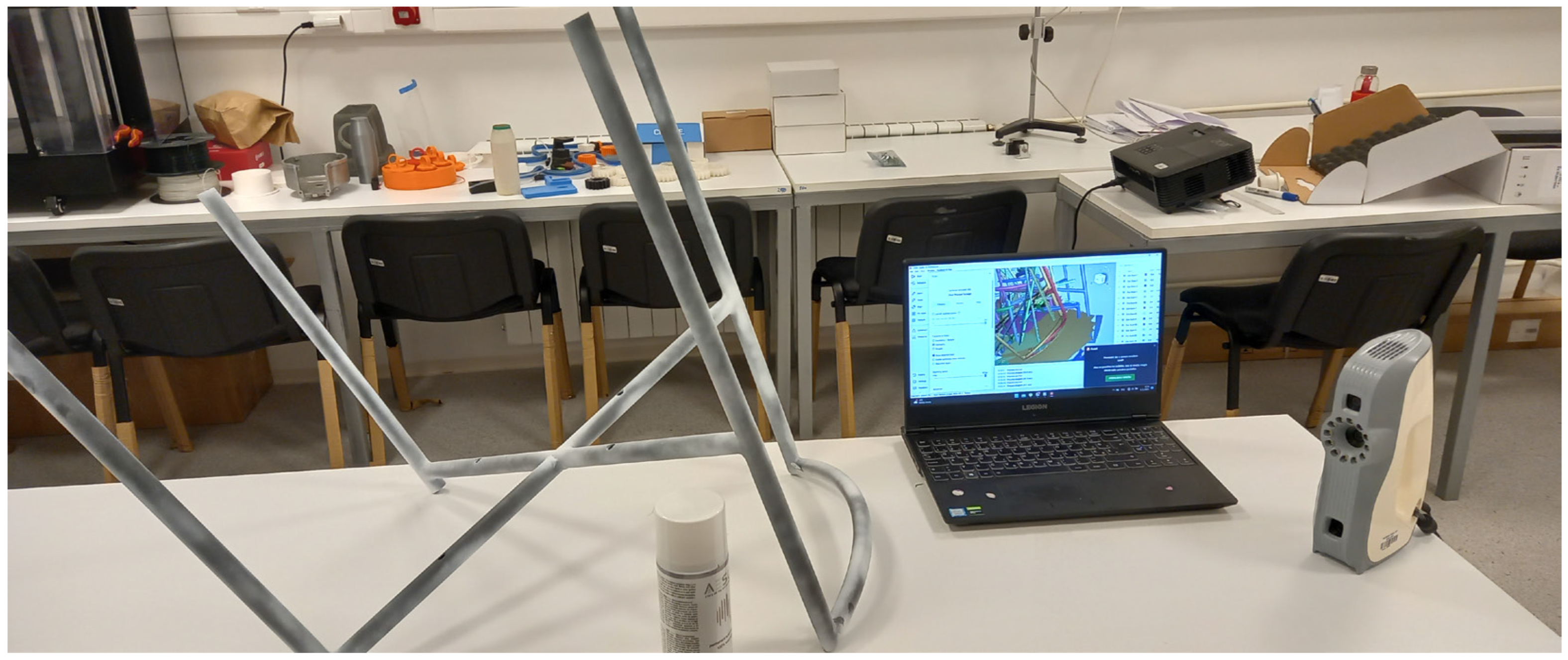
3.1. Experimental Setup

A portable hand-held 3D scanner was used (model Eva, Artec 3D, Luxembourg). Table 1 provides an overview of the scanner’s technical specifications. In-depth information can be found on the Artec 3D website [27].
Portable 3D scanners are suitable for 3D scanning medium-sized objects (from 30 cm up to 2 m). It is a perfect solution for the furniture industry. This structured light 3D scanner is suitable for making quick, textured and accurate 3D models of medium and large objects such as a human bust, an alloy wheel, a motorcycle exhaust system, or furniture products. It captures precise measurements quickly at high resolution. Light, fast, and versatile, Eva is one of the most popular scanners and a market leader in hand-held 3D scanners. Based on safe-to-use structured light scanning technology, it is an excellent all-around solution to capture objects of almost any kind, including objects with black and shiny surfaces [27]. All the 3D scans were processed using Artec Studio software (v. 15, Artec 3D, Luxembourg).
Three-dimensional scanning requires high computing power, especially when working with many scans containing many points. This research used a workstation with an Intel Core i7 processor, 32GB of RAM, and a Nvidia GeForce RTX 2060 graphics card (Legion 5 Pro Gen 8, Lenovo Group Limited, Hong Kong, China). This workstation is shown in Figure 1. In the first step, all scans were cleaned, aligned, and registered globally, and then a point-cloud 3D model was created (as an STL file). In the next step, this point-cloud 3D raw model must be imported into CAD software, such as Geomagic DesignX (3D Systems Corp., Rock Hill, SC, USA), SolidWorks (Dassault Systèmes, Vélizy-Villacoublay, France), or CATIA (Dassault Systèmes) to create a 3D CAD model. It is important to note that scanning is more manageable than creating a CAD 3D model using an STL 3D model as a reference. This process requires high engineering and 3D modeling skills. The created CAD model is then ready for manufacturing. Before manufacturing, it is vital to check the dimensional accuracy of the created CAD models compared to the scanned data. The 3D scanning process is presented in Figure 1.

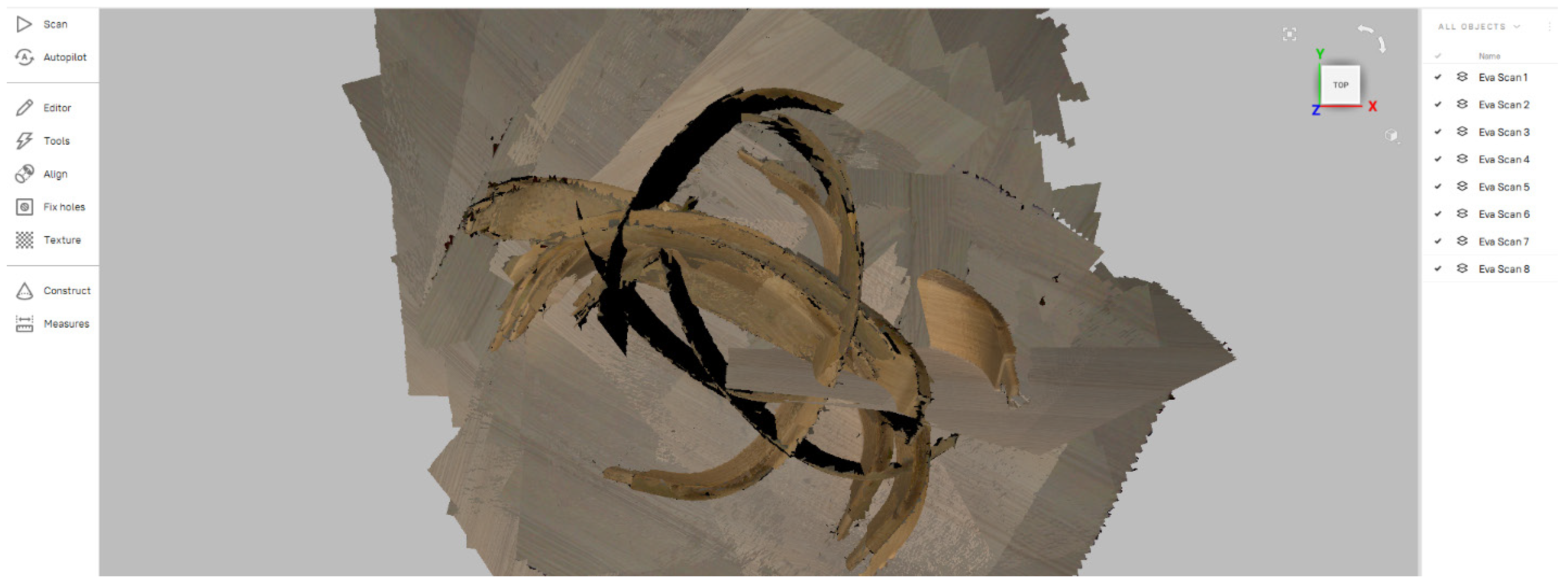
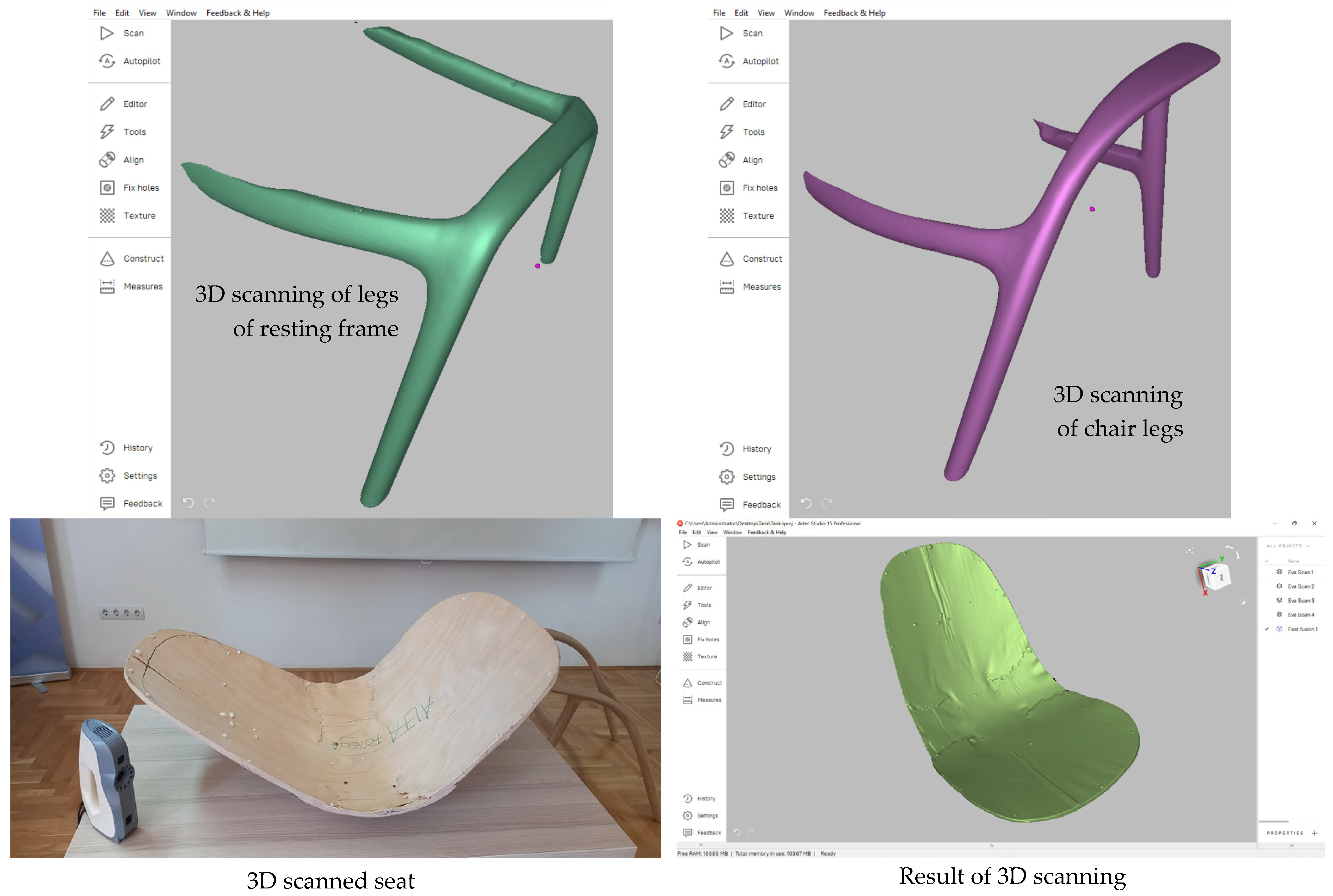
3.2. Three-Dimensional Scanning—Collect Raw Data

The first step utilized the Artec Eva 3D handheld scanner for 3D scanning. It is necessary to carry out enough scans from different sides of the object to capture all of the surface geometry. Scanned objects can be moved and rotated between scans. The 3D scanning raw data are presented in Figure 2. In this case, eight scans were captured.

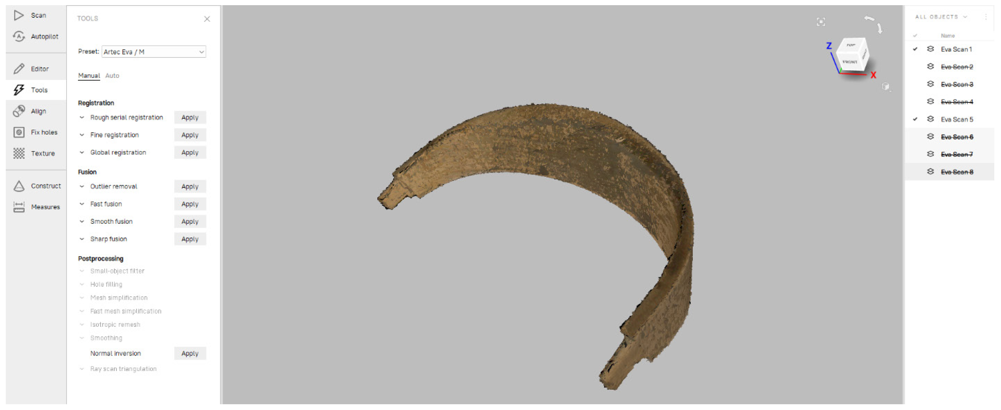
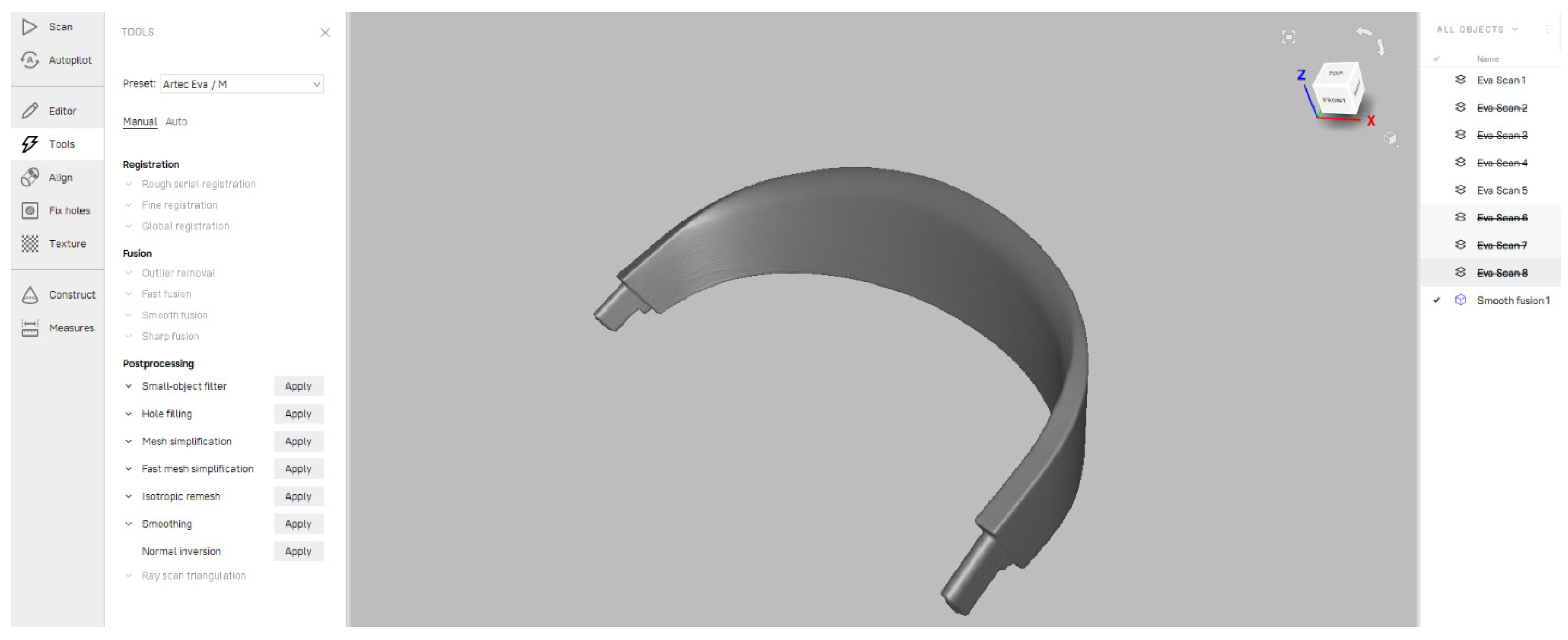
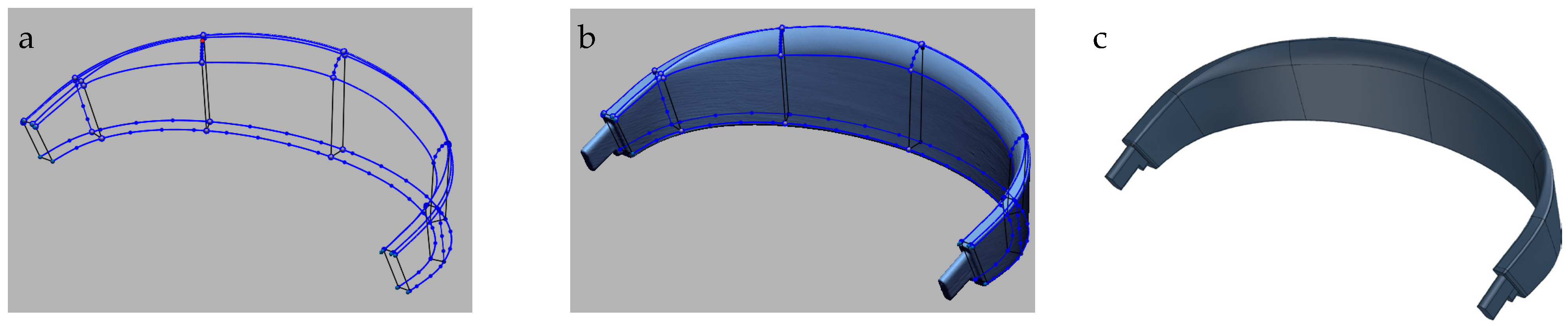
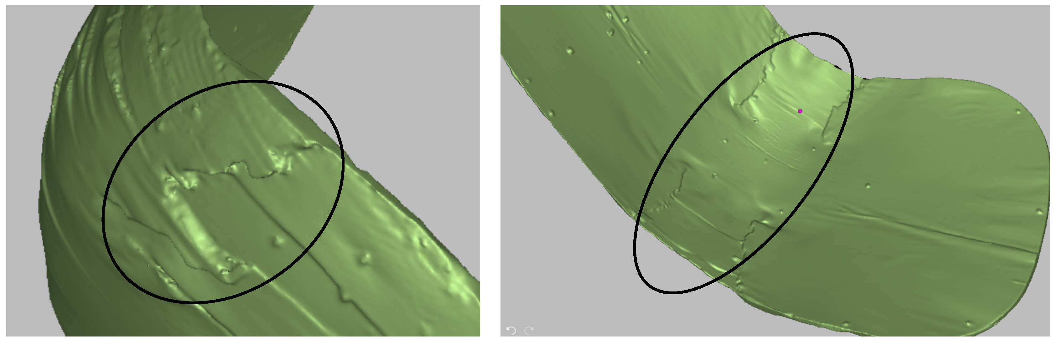
3.3. Processing of 3D Scans

The first step in raw data processing is visually analyzing the captured scans and selecting only the scans needed to construct the 3D model. It is always the best solution to build the digital 3D model from the smallest possible number of scans, which reduces time and computational demands. To achieve an accurate 3D model, the team merged scans Nos. 1 and 5 (Figure 3). In the next step, selected scans need to be processed. Processing means that the base needs to be deleted, noise needs to be filtered, selected scans must be aligned, and registration needs to be conducted. All these options are available in scanner software and can be conducted automatically in most cases (Artec Studio software, v. 15). Sometimes, alignment must be performed manually for complicated scans. After alignment, global registration is required for aligned scans. The aligned scans are shown in Figure 4. The total number of polygons for all eight scans was 201,202,756. After processing, the final STL model had 375,563 polygons.
It is important to note that this was one of the authors’ first projects. Due to a lack of experience, eight scans were captured, but only two were used. Experience helps engineers optimize the number of scans needed.
The final step is to create a mesh model, as shown in Figure 5. The great advantage of the software used is that it is always possible to go back and fix errors during raw data processing or to carry out and add additional scans if necessary. The created mesh model can be aligned to one of the planes before exporting to the STL file.

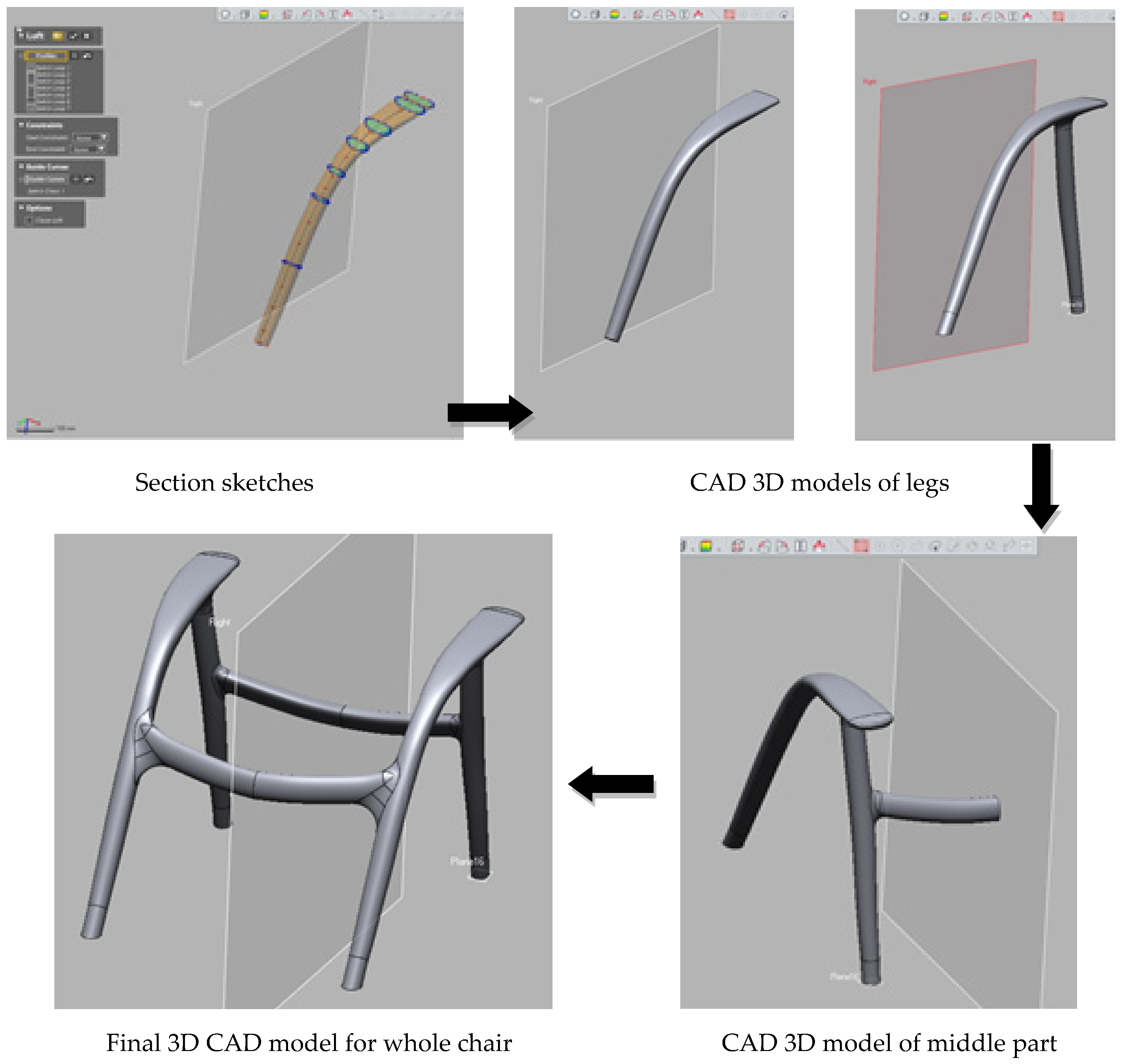
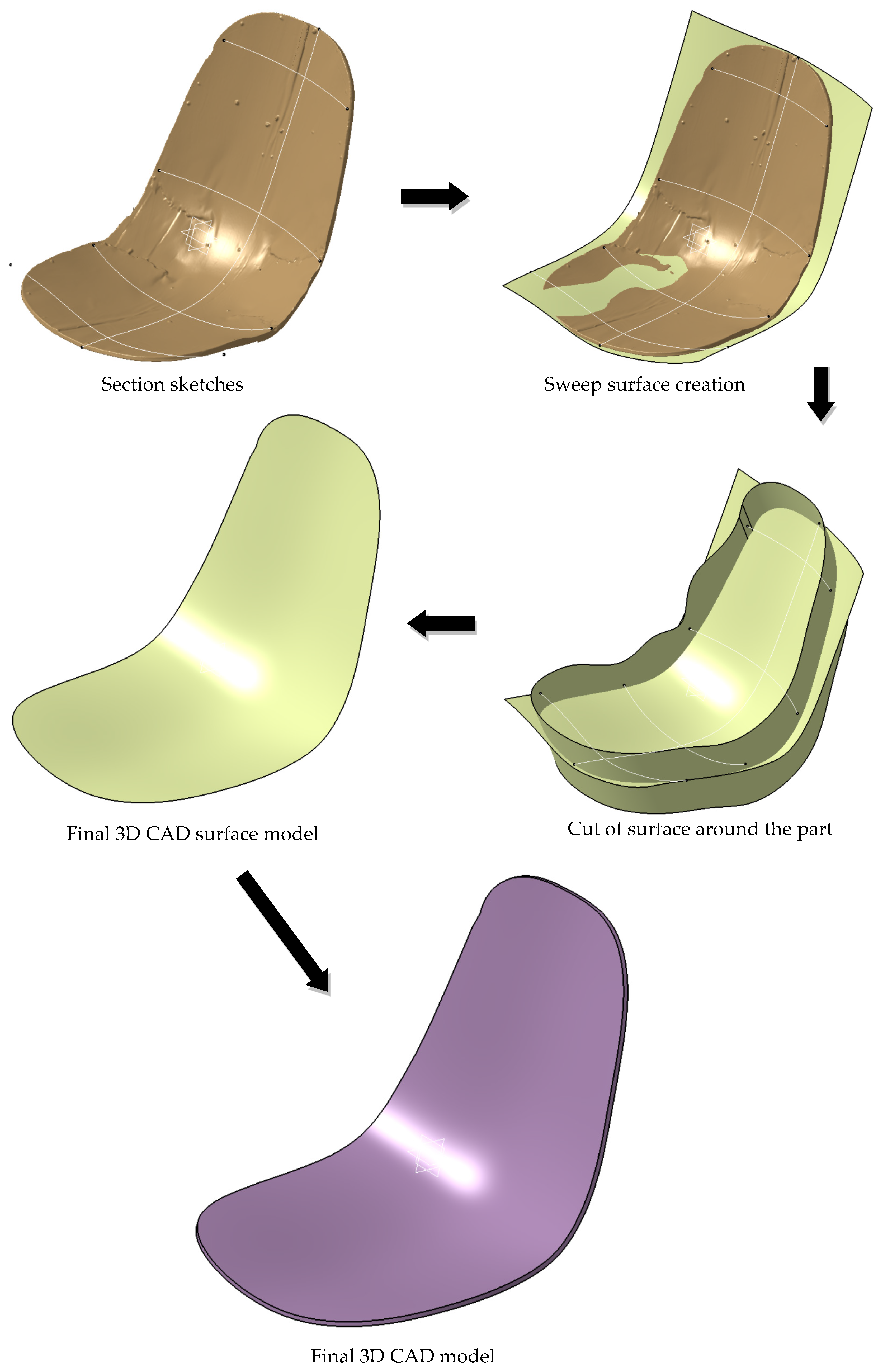
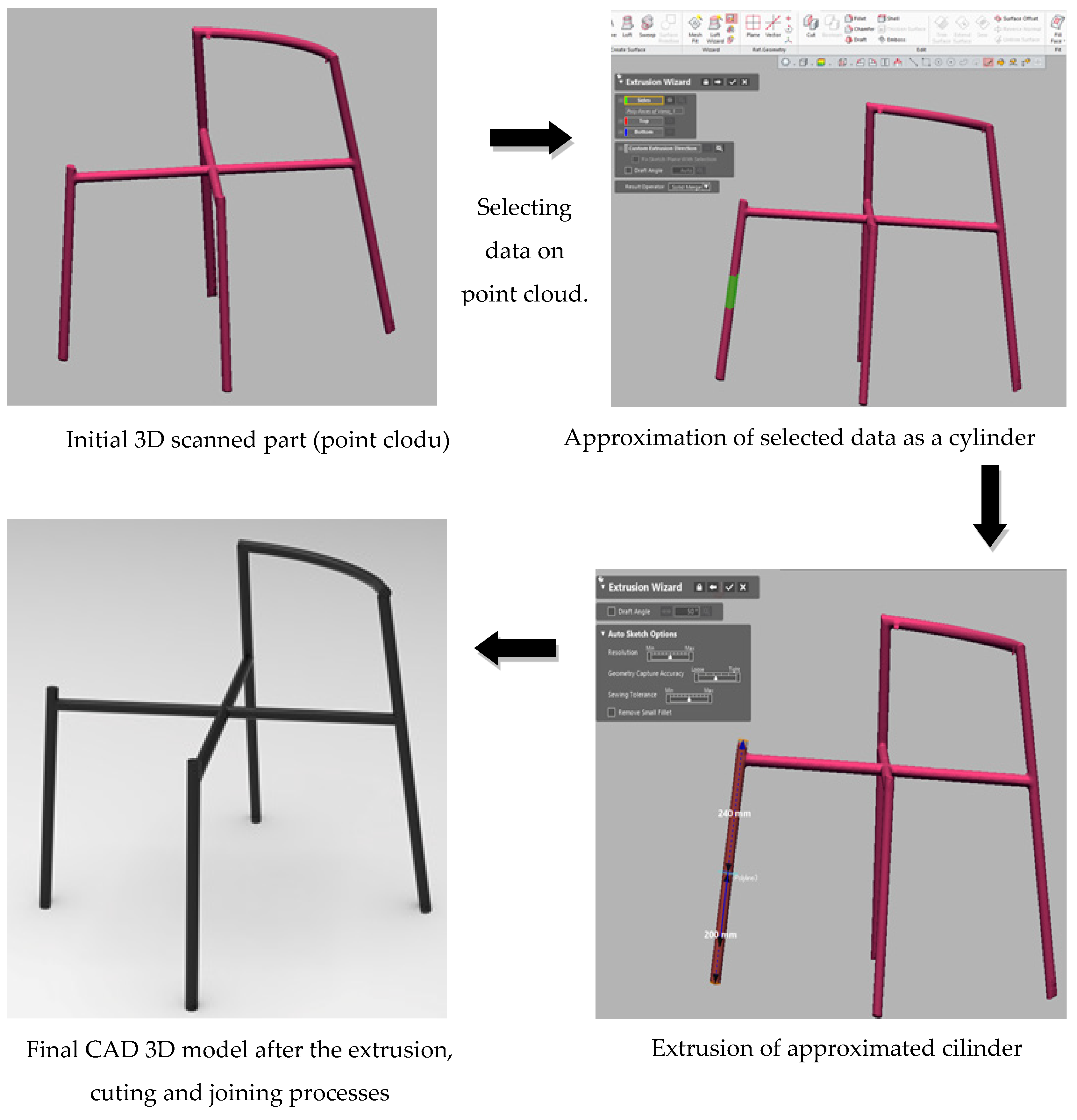
3.4. Development of CAD 3D Models

Although the mesh model in Figure 5 provides valuable visualization capabilities, it cannot be directly used in CNC machining or other automated manufacturing processes. Therefore, it was converted into a high-quality CAD 3D model using reverse engineering software (Geomagic DesignX, 3D Systems, Valencia, CA, USA). The reverse engineering software used has commands for the creation of CAD models using scanned mesh models only as a reference. It is easy to scan and process raw data, but to create a full-value 3D CAD model with topology, extensive knowledge and experience are needed.
The first step involved creating sketches using splines (Figure 6a). These sketches were then used to generate surface models (Figure 6b). Once the surface model was completed, a solid CAD model was created by adding volume to the surface (Figure 6c). Additionally, a small rectangular prong was added using the standard Part Design modeling procedures. This prong is not visible in Figure 6c because it did not require surface modeling with splines; its simple geometry could be created directly using Part Design tools. The solid model itself was generated through the regular Part Design modeling procedure, but with the scanned data serving as a crucial reference.

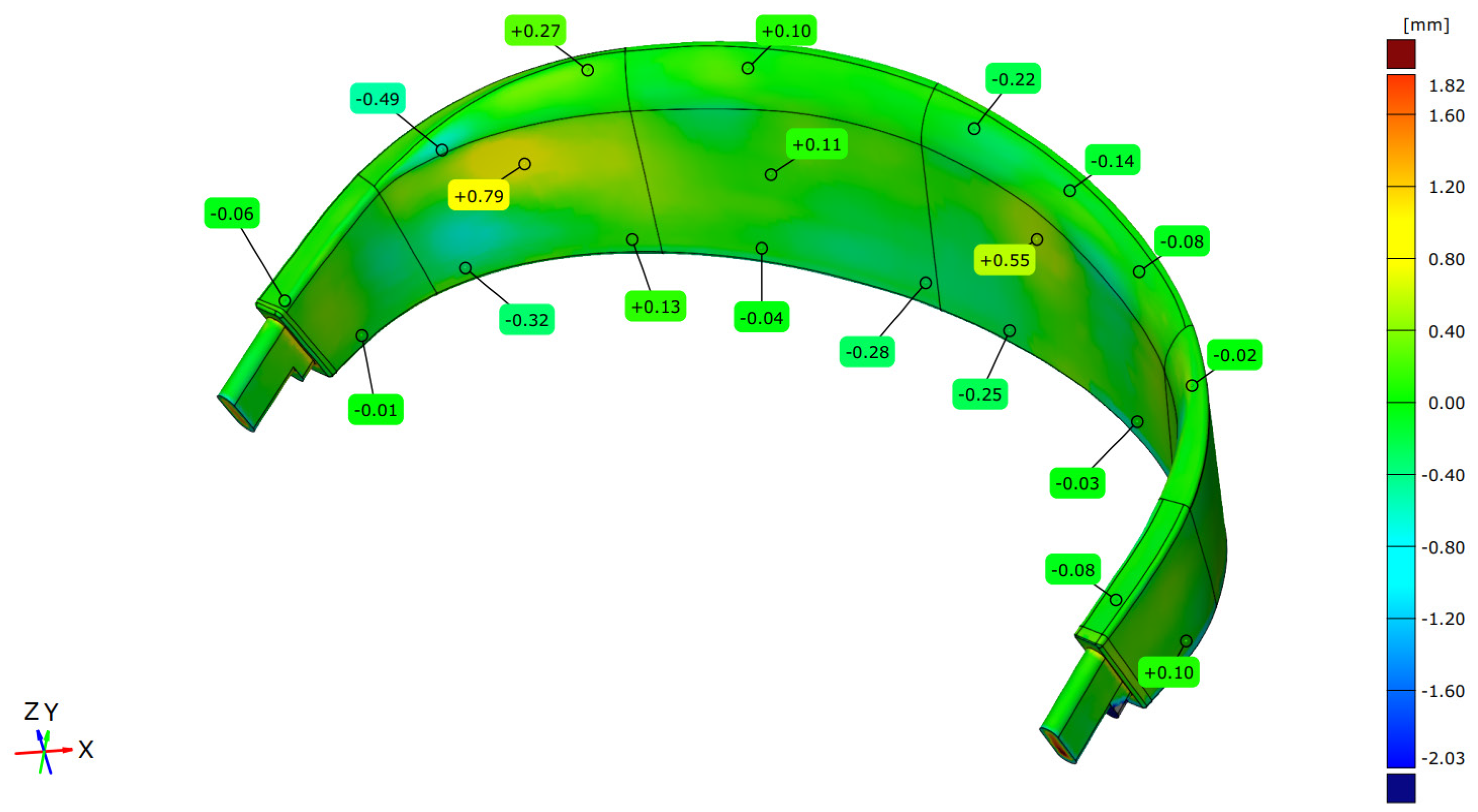
3.5. Analysis of the Dimensional Accuracy of Created CAD Models

The CAD model depicted in Figure 6 can be used for manufacturing. However, it is essential to compare the dimensions and tolerances with those of the 3D-scanned model to ensure precision. Therefore, inspection software (Zeiss Inspect Optical 3D v. 2023.2.0.1520, Carl Zeiss AG, Oberkochen, Germany) was employed. Inspecting software is usually used to measure the dimensional accuracy of manufactured parts. Manufactured parts are scanned in 3D, imported into inspection software, and correlated with the CAD model of the same part. In this case, the inspection software was used to check the quality of the CAD modeling. The created CAD models do not perfectly fit the scanned data so that some deviations may occur. In the furniture industry, all deviations below 1 mm can be accepted. Figure 7 presents the results of comparing the scanned model with the CAD model. The data in Figure 7 represent the distance values of the ideal CAD 3D model from the STL 3D point cloud model.

4. Results

4.1. Case Study No. 1

The undertaking described as c‘ase study no. 1’ was conducted by the Faculty of Mechanical Engineering at the University of Sarajevo, collaborating with Bosnia and Herzegovina’s Aptha Corporation as the producer. Stefano Bigi, an Italian furniture designer, was author of the design of the analyzed piece of furniture.
The design process began with creating initial concept models in real size by hand. These physical models were then brought into the digital realm using 3D scanning technology. These scan data, initially in the form of a point cloud (STL 3D model), were the foundation for creating CAD 3D models suitable for manufacturing. Figure 8 illustrates a prototype of a product designer’s lounge chair undergoing 3D scanning.
In the first step, the product designer created a digital design. In the second step, the mechanical engineers used that digital design to produce the first prototype. After a visual and practical examination of the first prototype, the designer was not satisfied with the chair’s shape, look, ergonomics, and practical aspects, so he used hand tools for grinding and polishing to create a new, modified prototype. The problem is that the latest prototype did not match the 3D CAD models, so it was impossible to manufacture more chairs with the modified design. It was necessary to 3D scan the new design and use 3D-scanned models to create new CAD models ready for manufacturing.
A mainly blended command was used for chair legs, combining cross-sectional sketches and mirroring another side. The CAD modeling is shown in Figure 9; the same method was used for the squat part of the legs.
The 3D modeling began with standard surface modeling techniques applied to the raw scanned raw data (point cloud). This involved creating multiple splines across the scanned surface. Next, a sweep command was used to generate the initial surface model. This surface was then refined by cutting it along the edges of the scanned data. Finally, a thickness of 10 mm was applied to create the solid 3D CAD model (Figure 10). This lounge chair comprises legs, a seat, and a separate part to rest the legs. The final form after manufacturing is shown in Figure 11. In this case, the scanning time of all three parts takes around 2 h, the processing of all scans for all three parts takes around 5 h, and 3D modeling (reverse engineering) takes an additional 6 h.
The analyses of the dimensional precision for the legs and seat are shown in Figure 12. The dimensional accuracy analysis is carried out only on one side of the chair because one side is scanned in 3D and another is created using the mirror command during 3D modeling (Figure 9).
A dimensional analysis of the lounge chair seat (Figure 13) confirms deviations well below 1mm, which is well within the acceptable tolerances for furniture manufacturing. It is important to note that for laminated wood components pressed and deformed like this seat, achieving extremely high dimensional accuracy throughout the entire structure might not be necessary. The production process can introduce minor cracks and delaminations (Figure 14). These imperfections are acceptable in this case, as the final product will be upholstered with soft material, effectively hiding them. In such components, dimensional deviations of up to several millimeters might be accepted.

4.2. Case Study No. 2

The second example of 3D scanning in the furniture industry is the case study where a 3D CAD model of an already manufactured chair part was needed.
This is the case where it is necessary to reproduce the same part but the part does not have any technical documentation. In this case, the frame of the chair must be manufactured using welded pipes (Figure 15). The frame has complex geometry that cannot be measured using traditional techniques (contact methods). This project was supported by the Standard Furniture Factory (Ilija, Bosnia and Herzegovina). In this case, the scanning time, scan processing, and 3D modeling (reverse engineering) took around 1 h each.
Reverse engineering of this part was performed using Geomagic DesignX software. The whole part is manufactured from the same diameter pipes, enabling an easy reverse engineering process. The extrusion wizard command was used. This command allows the user to select some part of the data from the scanned STL model, and the command automatically recognizes the shape of the selected data and approximates its dimensions. In this case, the command recognizes that a cylinder is the best approximation for these data. In the second step, this cylinder was extruded to the end of the pipes. This process was repeated for all parts. In the third step, the created extrusions of all pipes are cut and joined to form one part. This entire process is shown in Figure 16. After creating an ideal CAD 3D model, this product is reproduced using traditional pipe cutting and welding processes at the Standard Furniture Factory (Ilija, Bosnia and Herzegovina).
The analysis of dimensional accuracy for this case study is shown in Figure 17. It can be noticed that all deviations of the created CAD model compared to the 3D scanned point cloud are around 1 mm, except for the left rear leg. This deviation results from errors during the 3D scanning process, and the scanner does not detect the surface of the real part due to errors during the 3D scanning. There was a hole in the point cloud in this area. The software automatically filled this hole. This was not a problem for future processing of the part because, for 3D modeling purposes, the right rear leg was used and then mirrored to the left side. It can be seen that this part is symmetric from the left to the right.

4.3. Case Study No. 3

The phases of the third case study are presented in Figure 18. In this case, it was also necessary to reproduce the already manufactured part sent by the client without any technical documentation. The first step was to 3D scan to create 3D CAD models. The CAD models were then used for tool die manufacturing using the robot hand. After that, a manufactured tool die was used to reproduce the same part on a large scale. The entire reverse engineering is presented in Figure 18. This project was carried out in cooperation with the Wood Team d.o.o (Ilija, Bosnia and Herzegovina). As in case study No. 2, the scanning time, scanning processing, and 3D modeling (reverse engineering) took around 1 h each.

4.4. Case Study No. 4

The fourth example shows the necessity of developing and designing a new table support part using an old design in the Austro-Hungarian style (Figure 19). The old defective part was 3D scanned; scanned data were then used to produce a new part. This example has more complex shapes and surfaces, so scanning and scan processing take around 2 h. In this case, 3D modeling was not performed because this product will be reproduced by using sand casting. If the sand-casting manufacturing method is used, the surface quality of the 3D model does not need to be in the form of an ideal CAD model; the STL file can be used. Furthermore, superior surface quality is not necessary for this type of furniture. This 3D model can be used as an STL file. A missing leg can be easily added inside Artec Studio software using the scanned leg as a reference. Additionally, only one leg can be 3D printed and used for sand casting tool manufacturing. It is better to print only one leg due to the material serving for 3D printing. This case study is an excellent example of how additive manufacturing (3D printing) and reverse engineering (based on 3D scanning) can significantly influence and modernize old manufacturing processes like sand casting.

5. Discussion

The first analyzed case study discusses using 3D scanning to digitalize initial concept designs created by designers or architects. Hand-created designs are scanned into STL 3D models for manufacturing. An example is the 3D scanning of a lounge chair prototype. The designer then modified the design using hand tools, but it did not match the existing CAD models, requiring new scanning and CAD model creation. This iterative approach allowed the development of a piece of furniture of high-quality design. Three-dimensional scanning digitalizes the initial concept designs created by the product designer. Physical models can be converted to 3D digital CAD models, which can then be analyzed, modified, and stored [29]. This technology is becoming essential for producers who require accurate dimensional inspection, virtual imaging, analysis, and even physical prototype manufacturing in the early design stage [5,11]. Three-dimensional scanning is used in various industries, such as the automotive, healthcare, architecture, and furniture industries [5]. It enables the reverse engineering of complex curved surfaces [30,31] and the preparation of production systems [32]. Additionally, 3D scanning is used in the industry to develop business attire patterns by integrating 3D customer data obtained through the scanning process [33].
Three-dimensional scanning is used to digitalize furniture parts when there is a lack of technical documentation [34]. This scanning application is presented in the second case study. The use of 3D scanners also allows the analysis of deviations in model surfaces, dimensional deviations, and geometric tolerances [20] (second and third case study). This information helps to maintain production quality by controlling geometry errors in the production process [3]. Smart factories can enhance quality and gain a competitive advantage using 3D metrological data [35]. The fourth analyzed case study enables us to obtain geometric documentation of objects within history and the arts, allowing conservation and safeguarding of cultural heritage [36]. The application of 3D digital technologies in the conservation of cultural heritage has proven to help improve the collection, storage, and consultation of information and data related to diagnostic and restoration work [36]. Therefore, 3D scanning can be utilized to document furniture parts digitally and aid in their preservation and restoration, even in the absence of technical documentation.
From the literature review and the four case studies presented, it can be concluded that 3D scanning and reverse engineering have become integral parts of today’s industry in cases where new product development and design are needed. It is used in almost all development, design, manufacturing, and quality control aspects [6]. In the case of Bosnia and Herzegovina, it is used extensively in the furniture industry, especially for reverse engineering and design and development of new products. Also, in the case of the old-style table support, it can be seen how reverse engineering, together with 3D scanning and 3D printing, can bring significant improvement to old manufacturing processes.
Three-dimensional digitization in the furniture industry can be applied in various domains.
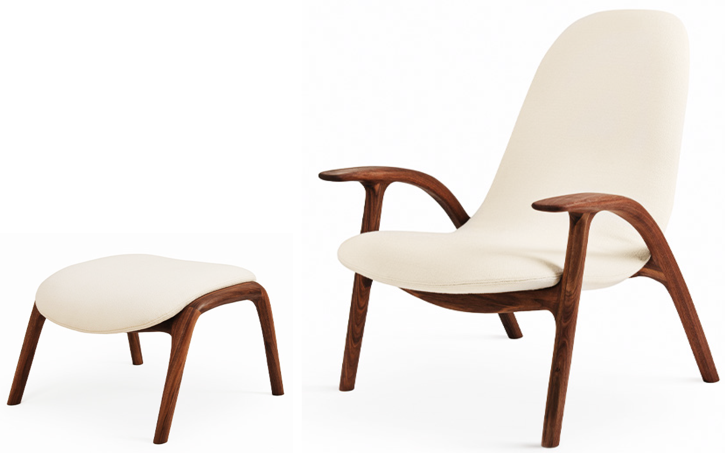
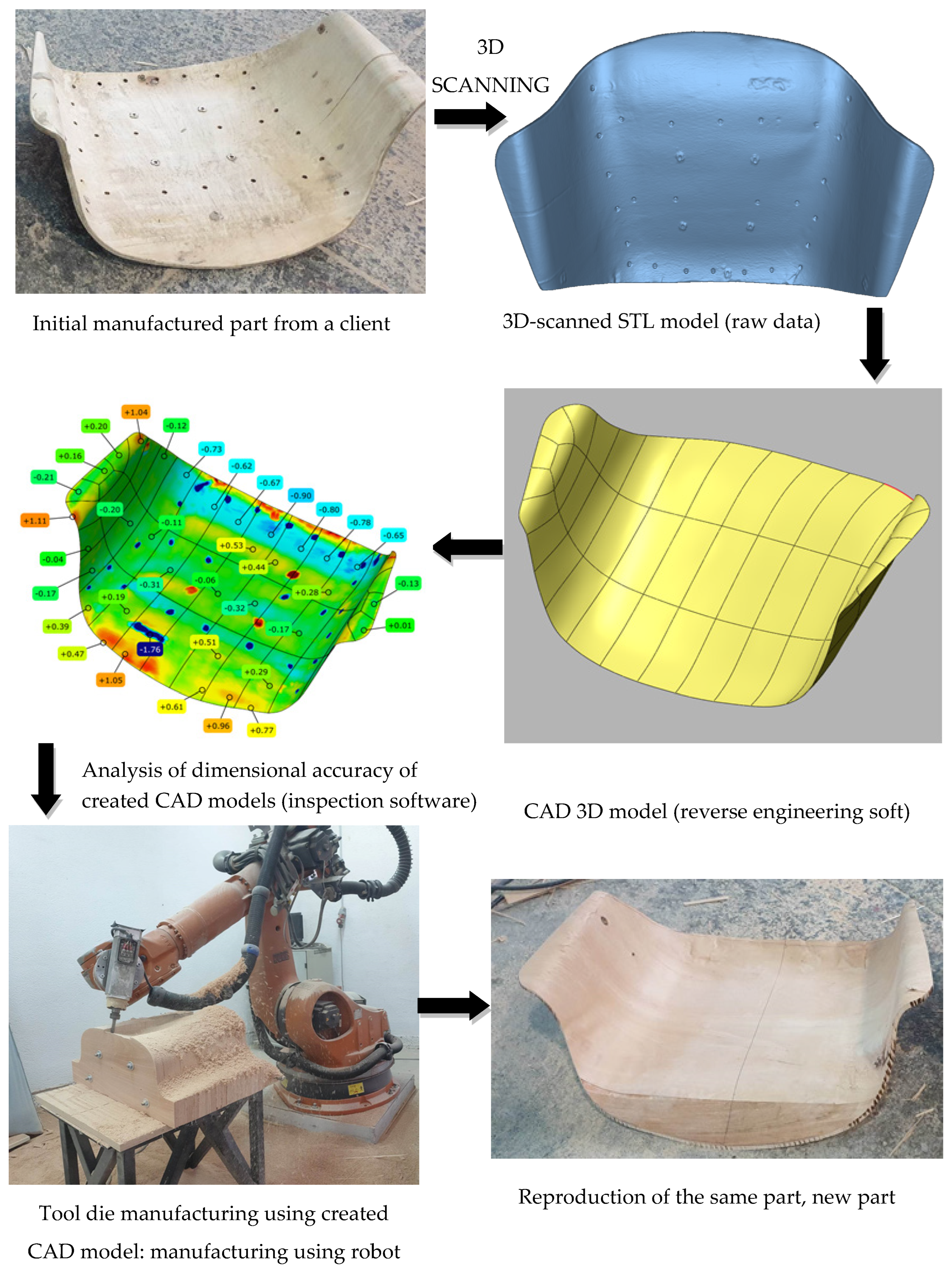
  • The designer often assembles the initial full-scale prototypes of designed furniture items manually. To replicate these prototypes in large-scale or series production using traditional manufacturing methods such as CNC machining, engineers must create a 3D CAD model. When generating 3D CAD models from physical objects, 3D digitization offers the most time-efficient and dimensionally accurate solution. Case study No. 1 showcases a practical application of this technology.
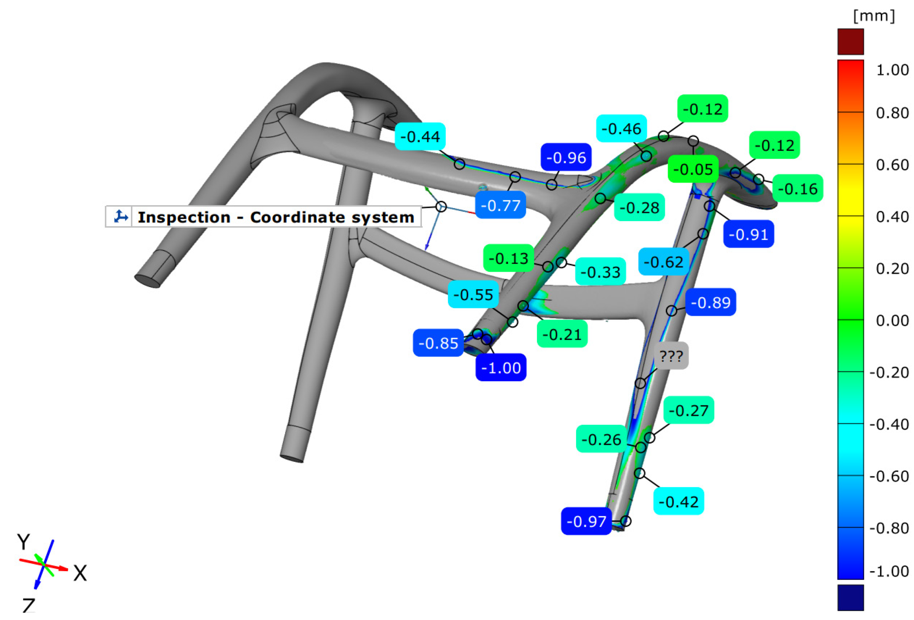
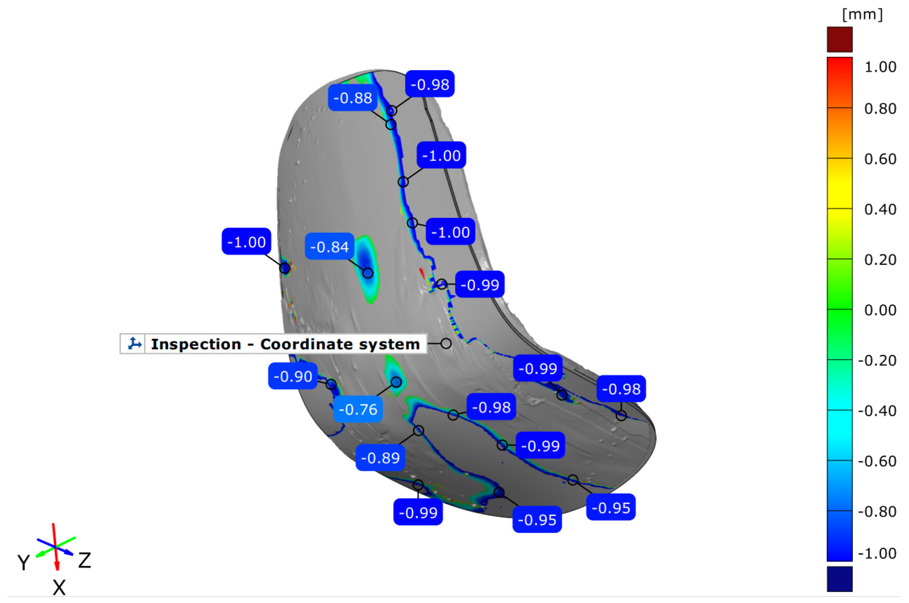
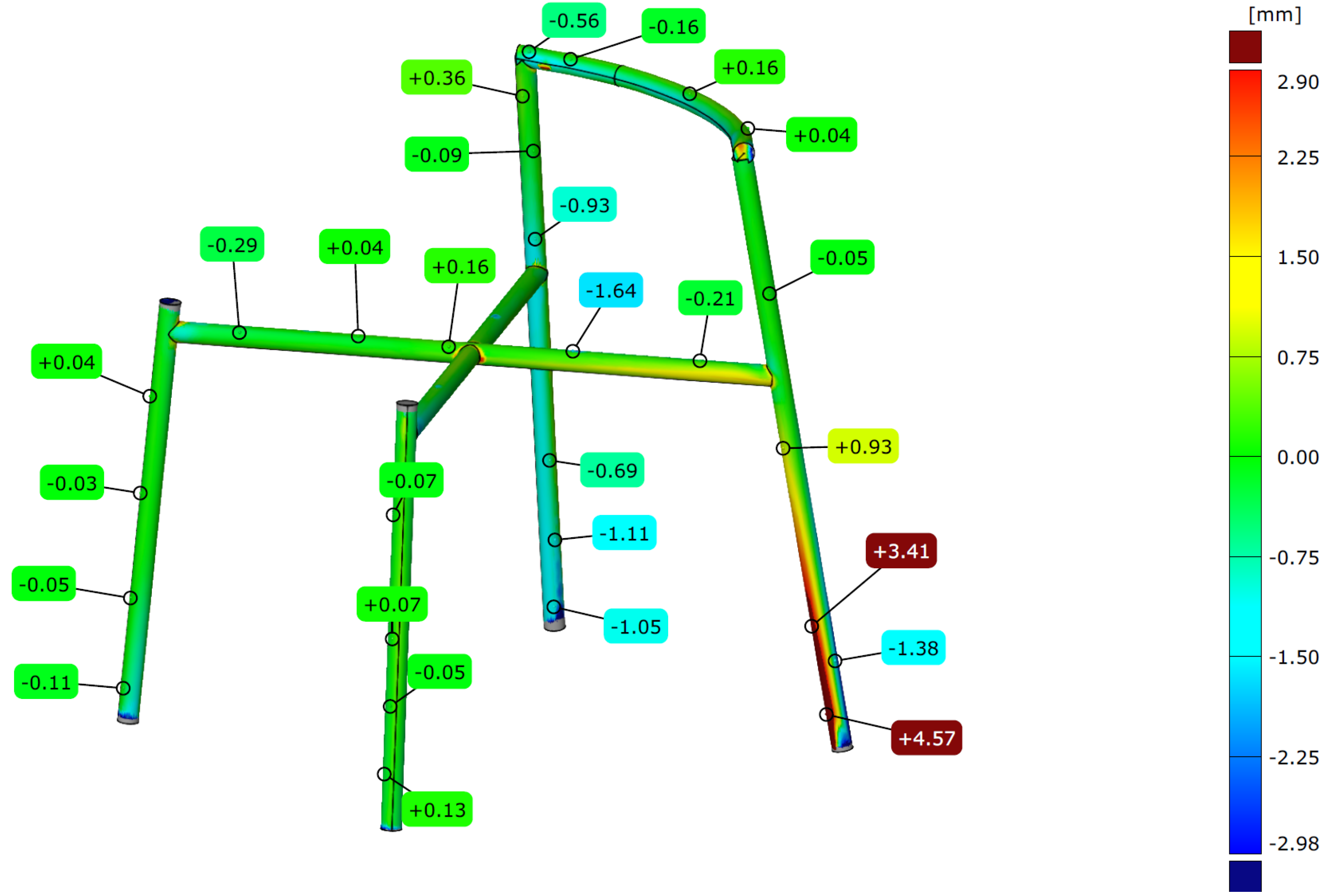
  • The primary area of utilization of 3D digitization in furniture production is metrology, which is used to verify the dimensional precision of fabricated components. A virtual point cloud 3D representation can be generated using 3D digitization, and this representation can be juxtaposed with the ideal 3D CAD representation of the same product so dimensional discrepancies can be gauged. This is not a frequently utilized application of 3D digitization in furniture because furniture items typically do not necessitate high dimensional precision. Examples of these applications are scientific documents [20] and [22] and case studies No. 2 and 3.
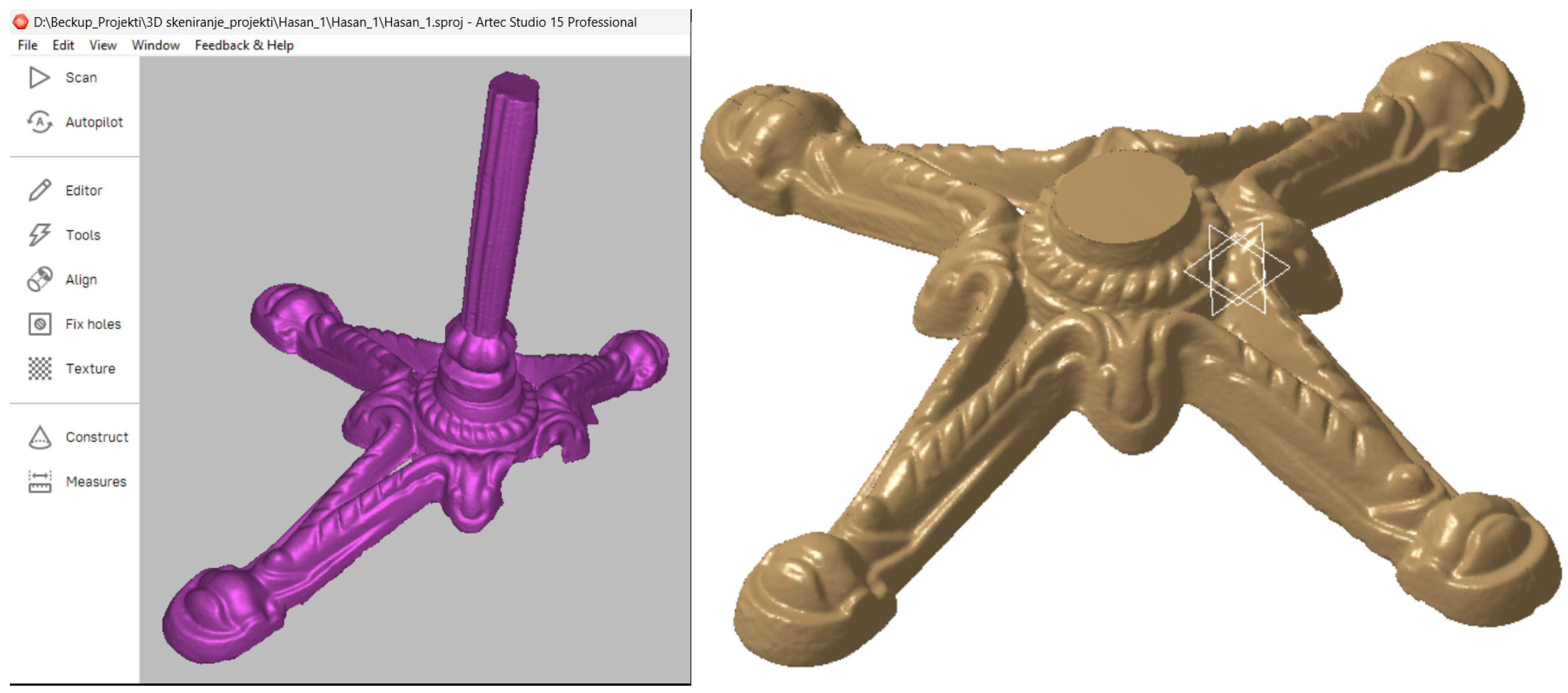
  • Three-dimensional scanning can preserve and reconstruct antique furniture. Digital storage eliminates the complexities of storing actual antique furniture. Additionally, digital representation can be easily distributed to others and is openly accessible to everyone worldwide for analysis. This application is illustrated in the literature [17,18,19] and case study No. 4.
  • Furniture production firms often need to replicate more duplicates of previously manufactured products (reverse engineering). Technical documentation of these products is often deficient or nonexistent. Faithfully reproducing these products begins with 3D digitization as a foundation for CAD representation. These application illustrations are featured in case studies No. 1, 2, and 3.
For furniture manufacturers seeking to increase efficiency in new product development and design, integrating 3D scanning technology offers significant advantages. Presently, 3D scanners, particularly those with standard precision levels, are relatively affordable and suitable for furniture manufacturing purposes, exhibiting the potential to accelerate new product development and the design process substantially. Three-dimensional scanning technology significantly reduces the time required to progress from initial sketches to a final product.
Furthermore, from the presented case studies, it is clear that knowledge of 3D scanning, reverse engineering, and additive manufacturing (3D printing) has become one of the most essential skills for today’s engineers and designers.

6. Conclusions

By exploring the current applications of 3D scanning in the furniture industry, this article studies the factors that determine when, why, and how 3D scanning can most benefit furniture design and production. Four real-world case studies demonstrate the combined 3D scanning and 3D CAD modeling in furniture creation.
The literature review and real-world furniture industry examples demonstrate the value of 3D scanning for the following key applications:
  • Three-dimensional scanning allows the creation of accurate 3D CAD models from physical prototypes, streamlining the development process of new furniture.
  • Manufacturers can verify the dimensional accuracy by comparing the scanned components with the CAD models, leading to a higher-quality end product.
  • Three-dimensional scanning facilitates the preservation, analysis, and reconstruction of antique furniture pieces.
  • This technology enables replicating existing furniture products, even with incomplete or missing technical documentation.
The literature review and case studies presented highlight a crucial skill set for today’s furniture engineers and designers, including proficiency in 3D scanning, reverse engineering, and additive manufacturing (3D printing).

Author Contributions

Conceptualization, A.J.M.; methodology, H.R., Ł.G. and J.S; software, H.R.; validation, A.J.M.; resources, A.J.M., Ł.W. and J.S.; writing—original draft preparation, A.J.M., Ł.G. and M.S.; writing—review and editing, V.H., M.T., B.W., N.P., Ł.G., M.S. and Ł.W.; visualization, A.J.M., H.R., W.Ł. and J.S.; supervision, A.J.M. and Ł.G.; project administration, A.J.M.; funding acquisition, A.J.M. and Ł.G. All authors have read and agreed to the published version of the manuscript.

Funding

This research was funded by the Ministry for Science, Higher Education, and Youth of Canton Sarajevo, 71000 Sarajevo, Bosnia and Herzegovina; grant number (45/1235).

Data Availability Statement

The data presented in this study are available upon request from the first author.

Conflicts of Interest

Author Jasmin Smajić was employed by the company Protodeves. The remaining authors declare that the research was conducted in the absence of any commercial or financial relationships that could be construed as a potential conflict of interest.

References

  1. Batra, V.; Kumar, V. Developments in Three-Dimensional Scanning Techniques and Scanners. In Emerging Trends in Mechanical Engineering; Das, L.M., Kumar, N., Lather, R.S., Bhatia, P., Eds.; Lecture Notes in Mechanical Engineering; Springer: Singapore, 2021; pp. 59–88. ISBN 9789811583032. [Google Scholar]
  2. Zheng, P.; Wang, H.; Sang, Z.; Zhong, R.Y.; Liu, Y.; Liu, C.; Mubarok, K.; Yu, S.; Xu, X. Smart Manufacturing Systems for Industry 4.0: Conceptual Framework, Scenarios, and Future Perspectives. Front. Mech. Eng. 2018, 13, 137–150. [Google Scholar] [CrossRef]
  3. Javaid, M.; Haleem, A. Industry 4.0 Applications in Medical Field: A Brief Review. Curr. Med. Res. Pract. 2019, 9, 102–109. [Google Scholar] [CrossRef]
  4. Arvanitis, G.; Lalos, A.S.; Moustakas, K. Robust and Fast 3-D Saliency Mapping for Industrial Modeling Applications. IEEE Trans. Ind. Inf. 2021, 17, 1307–1317. [Google Scholar] [CrossRef]
  5. Haleem, A.; Javaid, M.; Singh, R.P.; Rab, S.; Suman, R.; Kumar, L.; Khan, I.H. Exploring the Potential of 3D Scanning in Industry 4.0: An Overview. Int. J. Cogn. Comput. Eng. 2022, 3, 161–171. [Google Scholar] [CrossRef]
  6. Skorupińska, E.; Hitka, M.; Sydor, M. Surveying Quality Management Methodologies in Wooden Furniture Production. Systems 2024, 12, 51. [Google Scholar] [CrossRef]
  7. Krawiec, P.; Domek, G.; Warguła, Ł.; Waluś, K.; Adamiec, J. The Application of the Optical System ATOS II for Rapid Prototyping Methods of Non-Classical Models of Cogbelt Pulleys. MATEC Web Conf. 2018, 157, 01010. [Google Scholar] [CrossRef]
  8. Krawiec, P.; Czarnecka-Komorowska, D.; Warguła, Ł.; Wojciechowski, S. Geometric Specification of Non-Circular Pulleys Made with Various Additive Manufacturing Techniques. Materials 2021, 14, 1682. [Google Scholar] [CrossRef] [PubMed]
  9. Chowdary, B.V.; De Noon, A.; Ali, F.; Imbert, C.A.C. An Investigation for Improvement of the 3D-digitization Process: A Reverse Engineering Approach. J. Manuf. Technol. Manag. 2011, 22, 131–147. [Google Scholar] [CrossRef]
  10. Muminović, A.J.; Smajić, J.; Šarić, I.; Pervan, N. 3D Scanning in Industry 4.0. In Basic Technologies and Models for Implementation of Industry 4.0; Karabegovic, I., Ed.; Academy of Sciences and Arts of Bosnia and Herzegovina: Sarajevo, Bosnia and Herzegovina, 2023; pp. 231–240. [Google Scholar]
  11. Javaid, M.; Haleem, A.; Pratap Singh, R.; Suman, R. Industrial Perspectives of 3D Scanning: Features, Roles and It’s Analytical Applications. Sens. Int. 2021, 2, 100114. [Google Scholar] [CrossRef]
  12. Valero, E.; Adán, A.; Bosché, F. Semantic 3D Reconstruction of Furnished Interiors Using Laser Scanning and RFID Technology. J. Comput. Civ. Eng. 2016, 30, 04015053. [Google Scholar] [CrossRef]
  13. Jafri, S.R.U.N.; Hashmi, S.A.; Shabbir, A.; Mohsan, S.A.H.; Hadjouni, M.; Mostafa, S.M. Parametric Classification of Furniture From Point Cloud Developed Using Low Cost Trolley Based Laser Scanning System. IEEE Access 2023, 11, 51421–51434. [Google Scholar] [CrossRef]
  14. Badami, I.; Tom, M.; Mathias, M.; Leibe, B. 3D Semantic Segmentation of Modular Furniture Using rjMCMC. In Proceedings of the 2017 IEEE Winter Conference on Applications of Computer Vision (WACV), Santa Rosa, CA, USA, 27–29 March 2017; pp. 64–72. [Google Scholar]
  15. Fu, H.; Jia, R.; Gao, L.; Gong, M.; Zhao, B.; Maybank, S.; Tao, D. 3D-FUTURE: 3D Furniture Shape with TextURE. Int. J. Comput. Vis. 2021, 129, 3313–3337. [Google Scholar] [CrossRef]
  16. Miao, Y.; Jiang, H.; Jiang, L.; Tong, M. Research on 3D Reconstruction of Furniture Based on Differentiable Renderer. IEEE Access 2022, 10, 94312–94320. [Google Scholar] [CrossRef]
  17. Tsipotas, D.; Spathopoulou, V. An Assesment of Research on 3D Digital Representation of Ancient Greek Furniture, Using Surviving Archaelological Artefacts. In Proceedings of the 2015 Digital Heritage, Granada, Spain, 28 September–2 October 2015; pp. 325–328. [Google Scholar]
  18. Elgewely, E. 3D Reconstruction of Furniture Fragments from the Ancient Town of Karanis. Stud. Digit. Herit. 2017, 1, 409–427. [Google Scholar] [CrossRef]
  19. Wang, J. Application of 3D Data Scanning Technology in the Restoration and Protection of Ancient Furniture. In Proceedings of the 2021 2nd International Conference on Intelligent Design (ICID), Xi’an, China, 19 October 2021; Institute of Electrical and Electronics Engineers (IEEE): Piscataway, NJ. USA, 2021; pp. 161–165. [Google Scholar]
  20. Sydor, M.; Majka, J.; Rychlik, M.; Turbański, W. Application of 3D Scanning Method to Asses Mounting Holes Shape Instability of Pinewood. Materials 2023, 16, 2053. [Google Scholar] [CrossRef] [PubMed]
  21. Bodi, I.; Piperi, E.; Hoxha, M.; Kaçani, J. Evaluation of Surface Flatness and Roughness for Marble Products Produced with CNC Machining. In Proceedings of the Joint International Conference: 10th Textile Conference and 4th Conference on Engineering and Entrepreneurship, Tirana, Albania, 19–20 October 2023; Guxho, G., Kosova Spahiu, T., Prifti, V., Gjeta, A., Xhafka, E., Sulejmani, A., Eds.; Lecture Notes on Multidisciplinary Industrial Engineering. Springer Nature: Cham, Switzerland, 2024; pp. 325–333, ISBN 978-3-031-48932-7. [Google Scholar]
  22. Curta, R.; Zsolt, B.; Dragomir, M.; Comes, R.; Banyai, D. Methodology and Case Study in the Furniture Industry Using Photogrammetry and 5 Axis Machining. Acta Tech. Napoc. 2015, 58, 53–58. [Google Scholar]
  23. Anggraeni, M.E.; Risnumawan, A.; Maulana, M.R. 3D Reconstruction of Carved Furniture Products: Exploring Close-Range Photogrammetry Using Structure from Motion. In Proceedings of the 2023 IEEE 7th International Conference on Information Technology, Information Systems and Electrical Engineering (ICITISEE), Purwokerto, Indonesia, 29 November 2023; pp. 88–93. [Google Scholar]
  24. Daneshmand, M.; Helmi, A.; Avots, E.; Noroozi, F.; Alisinanoglu, F.; Arslan, H.S.; Gorbova, J.; Haamer, R.E.; Ozcinar, C.; Anbarjafari, G. 3D Scanning: A Comprehensive Survey. arXiv 2018, arXiv:1801.08863. [Google Scholar] [CrossRef]
  25. Kohtala, S.; Erichsen, J.F.; Wullum, O.P.; Steinert, M. Photogrammetry-Based 3D Scanning for Supporting Design Activities and Testing in Early Stage Product Development. Procedia CIRP 2021, 100, 762–767. [Google Scholar] [CrossRef]
  26. Kumar, L.; Shuaib, M.; Tanveer, Q.; Kumar, V.; Javaid, M.; Haleem, A. 3D Scanner Integration with Product Development. Int. J. Eng. Technol. 2018, 7, 220–225. [Google Scholar] [CrossRef]
  27. Description of the “Eva” 3D Scanner; Artec 3D: Luxembourg, Belgium, 2022; p. 6. Available online: https://cdn.artec3d.com/content-hub-files/artec-eva-brochure-eng-2023.pdf?VersionId=9MgbNRGVB5F.LyGmwy9Um3BTgI2kg6vm (accessed on 1 April 2024).
  28. Bigi, S. Alpha. Lounge Chair. GoEs, Hrasnica, Bosnia and Herzegovina. Available online: https://goes.ba/collection-alpha (accessed on 1 April 2024).
  29. Potangaroa, R. 3D Scanning as an Architectural Tool. IOP Conf. Ser. Earth Environ. Sci. 2022, 1007, 012001. [Google Scholar] [CrossRef]
  30. Kiatpanichgij, S.; Afzulpurkar, N.; Kim, T. Three-Dimensional Model Reconstruction from Industrial Computed Tomography-Scanned Data for Reverse Engineering: This Paper Presents a Semi-Automatic Method for Reconstructing a CAD Model from CT-Data. Virtual Phys. Prototyp. 2014, 9, 97–114. [Google Scholar] [CrossRef]
  31. Nguyen, W.L.K.; Aprilia, A.; Khairyanto, A.; Pang, W.C.; Seet, G.G.L.; Tor, S.B. Morphological Box Classification Framework for Supporting 3D Scanner Selection. Virtual Phys. Prototyp. 2018, 13, 211–221. [Google Scholar] [CrossRef]
  32. Lindskog, E.; Vallhagen, J.; Johansson, B. Production System Redesign Using Realistic Visualisation. Int. J. Prod. Res. 2017, 55, 858–869. [Google Scholar] [CrossRef]
  33. Rodriguez-Conde, I.; Campos, C. Towards Customer-Centric Additive Manufacturing: Making Human-Centered 3d Design Tools through a Handheld-Based Multi-Touch User Interface. Sensors 2020, 20, 4255. [Google Scholar] [CrossRef] [PubMed]
  34. Jurković, T.; Karakašić, M.; Kljajin, M. Optical Digitalization of a Spatial Model by Projecting Coded Light. Teh. Glas. 2015, 9, 12–17. [Google Scholar]
  35. Javaid, M.; Haleem, A.; Singh, R.P.; Rab, S.; Suman, R.; Kumar, R. Studies on the Metrological Need and Capabilities of 3D Scanning Technologies. J. Ind. Integr. Manag. 2023, 08, 321–339. [Google Scholar] [CrossRef]
  36. Selma Rizvić, A.C.; Sadžak, A.; Buza, E. Virtual Reconstruction and Digitalization of Cultural Heritage Sites in Bosnia and Herzegovina. Rev. Natl. Cent. Digit. 2008, 12, 82–90. [Google Scholar]
Figure 1. Methodology of 3D scanning and processing process.
Applsci 14 04112 g001
Figure 2. Result of 3D scanning (raw data).
Applsci 14 04112 g002
Figure 3. Selected scans Nos. 1 and 5.
Applsci 14 04112 g003
Figure 4. Scans Nos. 1 and 5 after alignment, noise filtration, and global registration.
Applsci 14 04112 g004
Figure 5. Created mesh model.
Applsci 14 04112 g005
Figure 6. Creating CAD model from scanned data using DesignX software: (a)—splines, (b)—surface model; (c)—solid model.
Applsci 14 04112 g006
Figure 7. Analysis of the dimensional accuracy of the created CAD models.
Applsci 14 04112 g007
Figure 8. Three-dimensional scan of the parts of the lounge chair.
Applsci 14 04112 g008
Figure 9. CAD modeling of the lounge chair legs.
Applsci 14 04112 g009
Figure 10. CAD modeling of the lounge chair seat.
Applsci 14 04112 g010
Figure 11. Manufactured lounge chair (right) with footrest (left) [28].
Applsci 14 04112 g011
Figure 12. Analysis of dimensional accuracy for lounge chair legs.
Applsci 14 04112 g012
Figure 13. Analysis of dimensional accuracy for lounge chair seat.
Applsci 14 04112 g013
Figure 14. Cracks and delamination of wood parts.
Applsci 14 04112 g014
Figure 15. Three-dimensional scanning of the chair frame.
Applsci 14 04112 g015
Figure 16. Reverse engineering of case study No. 2.
Applsci 14 04112 g016
Figure 17. Analysis of dimensional accuracy for case study No. 2.
Applsci 14 04112 g017
Figure 18. Reverse engineering and manufacturing of a chair part.
Applsci 14 04112 g018
Figure 19. Three-dimensional scanning of the Austro-Hungarian old-style table support, including scanned data (left); the full 3D model (right).
Applsci 14 04112 g019
Table 1. Technical specification of 3D scanner Artec Eva.
Technical SpecificationValue
3D accuracyUp to 0.1 mm
3D resolutionUp to 0.2 mm
Scanned object sizeLarger than 10 cm
Full-color scanningYes
Target-free trackingHybrid geometry and color-based
3D reconstruction rateUp to 16 frames per second
Output formatsAll popular formats, including STL, OBJ, and PLY
Disclaimer/Publisher’s Note: The statements, opinions and data contained in all publications are solely those of the individual author(s) and contributor(s) and not of MDPI and/or the editor(s). MDPI and/or the editor(s) disclaim responsibility for any injury to people or property resulting from any ideas, methods, instructions or products referred to in the content.

