Article

Weighting Failure Mechanisms of Pre-Driven Recovery Rooms and Evaluation of Hydraulic Fracturing Applications: A Case Study

1
School of Mines, China University of Mining & Technology, Xuzhou 221116, China
2
State Key Laboratory of Coal Resources and Mine Safety, Xuzhou 221116, China
*
Author to whom correspondence should be addressed.
Appl. Sci. 2023, 13(8), 5116; https://doi.org/10.3390/app13085116
Submission received: 1 April 2023 / Revised: 15 April 2023 / Accepted: 18 April 2023 / Published: 20 April 2023
(This article belongs to the Special Issue Advanced Underground Coal Mining and Ground Control Technology)

Abstract

:
Roof weighting failures of pre-driven recovery rooms may cause huge economic losses and even casualties. The excessive dynamic load from the sliding of the broken main roof rock block causes the recovery room roof and inner supports to lose their support capacity during the last weighting. Discrete element software UDEC was used to investigate the surrounding rock deformation of the pre-driven recovery room with the main roof break at different positions. The results show that when the recovery room’s length from the main roof rock layer’s fracture region is short, the immediate roof is subjected to high deviatoric stress and the occurrence of horizontal stress concentration due to the deflection of the fractured rocks, and eventually the roof supports fail owing to the development of macroscopic shear crack zones. In this research, the hydraulic fracturing technique was applied to pretreat the main roof (fine-grained sandstone) of the 31108 panel at Huoluowan Coal Mine. Field observations suggest that the strength and duration of the periodic weighting after hydraulic fracturing treatment are both significantly reduced, effectively maintaining the bearing layer performance of the roof of the recovery room and coal pillar walls. The proposed fracturing design offers an effective method of ground control to the coal mines facing roof weighting failures of recovery rooms.

1. Introduction

Pre-driven recovery rooms (PRR) allow for the installation of the necessary supports and reinforcement before the influence of the front abutment pressures, which provides a chance to improve the efficiency of moving mining machinery from the completed panel to the next working face to be extracted [1]. The longwall face advancing into the PRR is a critical step in the process of coal extraction, since it must ensure the roof stability of the PRR during this step so as to provide sufficient space for the retrieval of equipment such as shearers, scraper conveyors and shields [2]. However, catastrophic results such as casualty incidents and equipment damage often occur in some recovery work owing to improper supporting measures, or a failure in limiting the continuous subsidence of the roof strata. At the end of last century, the National Institute for Occupational Safety and Health (NIOSH) in America constructed a comprehensive worldwide database containing 130 case histories and found that roof failures of the PRR can be divided into two types. One type is a roof collapse generated by the weight of nearby friable roof as the fender (referring to the remaining coal body to be mined between the longwall face and the PRR) narrows. The width of fender pillar gets smaller as the mining machinery gets closer to the PRR. The abutment force inevitably transfers to the support system positioned in the PRR and the outby abutment pillar system. Heavy roof reinforcement was adopted to significantly reduce the incidence of such failure. Another type is an overburden weighting failure where the main roof fails to bridge the face area and the PRR, meanwhile damaging the rocks above the immediate roof. Strengthening of the roof structure was evidently not effective in eliminating weighting failures [3,4].
Over the past several years, in Chinese underground longwall mining practices, many coal mines in the Shendong mining district have encountered overburden weighting failures at the final stage of coal extraction, even though double-row chock hydraulic supports with extremely high strength have been employed in the PRR to minimize roof subsidence [5,6]. During the mining machinery entering the PRR, although the internal support is essential to establish an immediate roof beam that helps support the main roof, movement above the anchor layer is common, especially when the fracture region of the main roof is nearby the PRR in the last weighting [7,8,9]. The main force source of hydraulic support damage is the impact force generated by the unstable main roof rock block, and the strain energy stored in the broken rock block during structural instability is converted into kinetic energy of the rock block falling. This leads to non-static contact between the unstable rock block and the immediate roof below it, and the resulting contact collision phenomenon can produce an impact force much greater than the static self-weight of the main roof rock block in a short time. The impact force is transmitted directly to the face support through the immediate roof so that the support needs to bear the impact load it generates [10,11].
In order to lessen unfavorable impacts of the overburden weighting on the PRR, it is common to stop advancing the longwall face temporarily while the remaining fender is about 5 m wide, and wait for the signs of weighting on the work face. These signs usually include the increasing resistance of the shields and the aggravation of coal wall spalling. Then the face continues to progress until it enters the PRR. During the longwall stop period, the immediate roof behind the supports can fully collapse and the main roof strata experience a certain amount of rotation. Hence, to some extent yield mining is able to alter the periodic weighting position and reduce the duration of the weighting. Nevertheless, a notable drawback of yield mining is that it is complicated and difficult to determine a reasonable longwall stop position. This is because the weighting step is not a fixed length and the stop position obtained from experience may lead to severe support-crushing accidents on account of ground deformation and other factors [4]. Field practice shows that pretreating the main roof with hydraulic fracturing is able to promote the collapse of the roof rocks and then lower the possibility of dynamic loading disasters in longwall coal mining [12,13]. Therefore, in theory, the application of hydraulic fracturing can compensate for the shortcomings of yield mining.
To have a better understanding of the mechanical response of the PRR surrounding rocks when the main roof weighting is in the final mining period, a discrete element model is established in this paper based on the engineering and geotechnical situations of Huoluowan Coal Mine. The influence of subsidence movement of the detached main roof block with different positions on the PRR surrounding rock deformation and stresses are analyzed. Additionally, instruments are applied after fracturing the overlying strata to monitor the stresses on the hydraulic supports and the support bodies, the convergence from roof to floor and other mechanical behaviors in the PRR. Eventually, the effect of hydraulic fracturing on preventing the roof weighting failure is evaluated. Results show that the adopted fracturing scheme is capable of guaranteeing the recovery work is done safely and effectively.

2. Study Site

2.1. Geological Conditions

The Huoluowan Coal Mine is located in Shendong mining district, Ordos, Inner Mongolia. The coal seam 3-1 being mined has an average thickness of 4.4 m and a depth of 230 m and it is nearly a horizontal coal seam. The study site in this survey is the 31108 panel and the lithology conditions are shown in Figure 1. The main roof consists of fine-grained sandstone that is 21.14 m thick and below it a 6.2 m thickness siltstone immediate roof. The caving method is used to treat post-mining space. The variation value of the front abutment pressure and the width of the coal body located between the peak stress point and the coal wall were measured using borehole stress-meters. The test results show that the stress of the coal seam changes within a range of 20 m in front of the working face and the peak stress position is about 5 m away the coal wall during the face progression. Figure 2 illustrates the layout of the PRR of the 31108 panel. The coal pillar between the main PRR and secondary PRR of 31108 panel is 20 m wide.

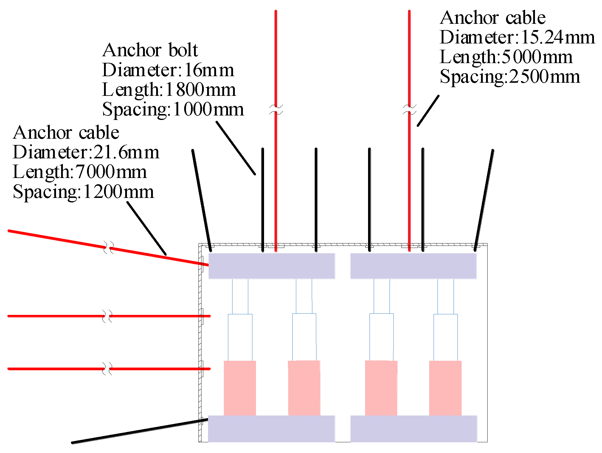
2.2. Support of the Main PRR

The roof of the main PRR is supported by a combination of rock bolts and cables. The size of the rock bolts is φ16 × 1800 mm and the row spacing is 1 m. The cables having a specification of φ15.24 × 5000 mm, are installed with a 2-1-2 periodic pattern and a row spacing of 2.5 m. The cables are connected by steel straps. Two rows of chock hydraulic roof supports are deployed below. The supporting height of hydraulic supports ranges from 2.5 m to 5 m, and has a yield load of 18,000 kN. The outby pillar rib is reinforced by rock bolts, cables and steel meshes. The rock bolts have a specification of φ16 × 1800 mm. The cables of φ21.6 × 7000 mm are installed on a row spacing of 1.2 m. A rebar bolt of φ22 × 2400 mm is arranged below. Each anchor bolt is anchored with a capsule resin. Each anchor cable is anchored with three capsule resins. The specifications of capsule resins in the roof and rib are, respectively, 23 mm × 500 mm and 35 mm × 500 mm. The diameters of the holes in the roof and rib are, respectively, 32 mm and 42 mm. The inby fender pillar rib is not reinforced to facilitate coal shearing when the face cuts into the PRR. Figure 3 provides a schematic diagram of the support design.

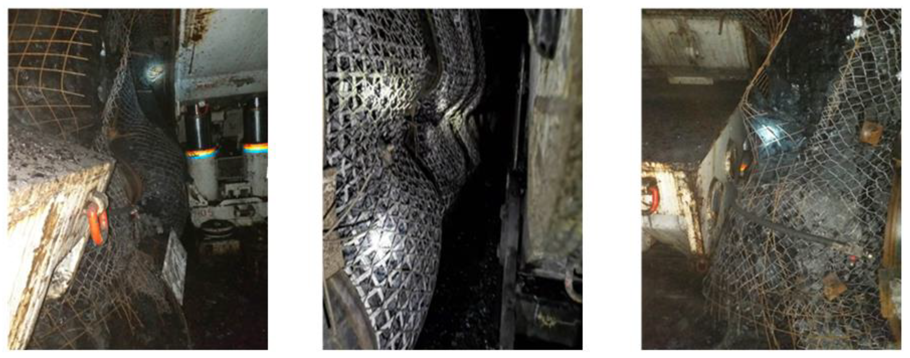
2.3. Potential Hazards

When other panels of this coal seam were extracted, serious roof weighting failures had occurred, even under the conditions of yield mining. In the course of coal excavation, the roof fell rapidly and violently in a short time, forming steps, and the anchor cables were fractured and ejected away. The deformation amount of the pillar rib in the main PRR exceeded 0.5 m, as shown in Figure 4. These exposed the operators to an unsafe working environment and increased the difficulty of the recovery work.

2.4. Roof Structure

According to practical experience in this coal mine, after the mining machinery is advanced into the PRR, the break key rock mass B of fine-grained sandstone can be behind, above the face supports or above the PRR in the last weighting [14], as shown in Figure 5. In Figure 5a, a periodic weighting happens before the mining machinery reaching the PRR and the fine-grained sandstone roof break line is behind the supports after the fender is mined out. Due to the small overhanging length of the main roof and the small amount of subsidence and deflection of the rocks above the supports, the stresses on the room supports and the face supports increase slightly and it is easy to transport the equipment. However, when the break positions are closer to the PRR during the overburden weighting, as shown in Figure 5b,c, reduction in the roof strength during the removal of the supports causes continuous subsidence and rotation of the rock mass B, resulting in serious rib spalling and even the occurrence of support-crushing accidents. During the longwall stop period, stress concentration on the inby fender often occurs.

3. Numerical Simulation

3.1. UDEC Trigon Model

In order to clearly reproduce the spalling of the inby fender and the subsidence of the roof in numerical modelling, the distinct element code UDEC is selected in this study. A rock mass in the UDEC Trigon model can be represented as a collection of triangular blocks joined at their contacts. These contacts will break if the force exerted on them exceeds their tensile or shear resistance [15]. The mechanical performance of triangular blocks is controlled by the Coulomb friction law, as indicated in Table 1. The UDEC Trigon model can offer an accurate representation of fracture initiation, propagation, as well as the behavior of the rock masses after failure. The effectiveness of the UDEC-Trigon method in studying fragile fracturing has been acknowledged and verified on scales ranging from the laboratory to the mine [16].

3.2. Model Establishment

The UDEC Trigon model was established to analyze the mechanical behavior of the surrounding rocks of the inby fender and the PRR as the breaks located at different positions in the main roof during the last weighting. The distance between the break line and the center of the PRR was set to be 0 m, 3 m, 6 m and 9 m, respectively, as shown in Figure 6. There was no vertical displacement at the bottom of the model and no horizontal displacement at the two vertical boundaries. The excavation length was 80 m and the fender width during the face stop was determined to be 5 m. According to in-situ stress measurements of this mining area [19], the vertical stress was 5 MPa, the maximum and minimum horizontal principal stresses were 6.3 MPa and 3.7 MPa, respectively, and the minimum horizontal principal stress was parallel to the model plane. The Mohr–Coulomb constitutive model was adopted. To improve the computational efficiency and facilitate the observation of the fracture distribution and the stress evolution, the UDEC Trigon logic was utilized to divide the surrounding rocks of the PRR into triangular blocks with an average size of 0.3 m. The block size was small enough in relation to the whole model and had been proven to accurately reflect the mechanical behavior of a rock mass [20]. Other areas of the model were divided into rectangular blocks.

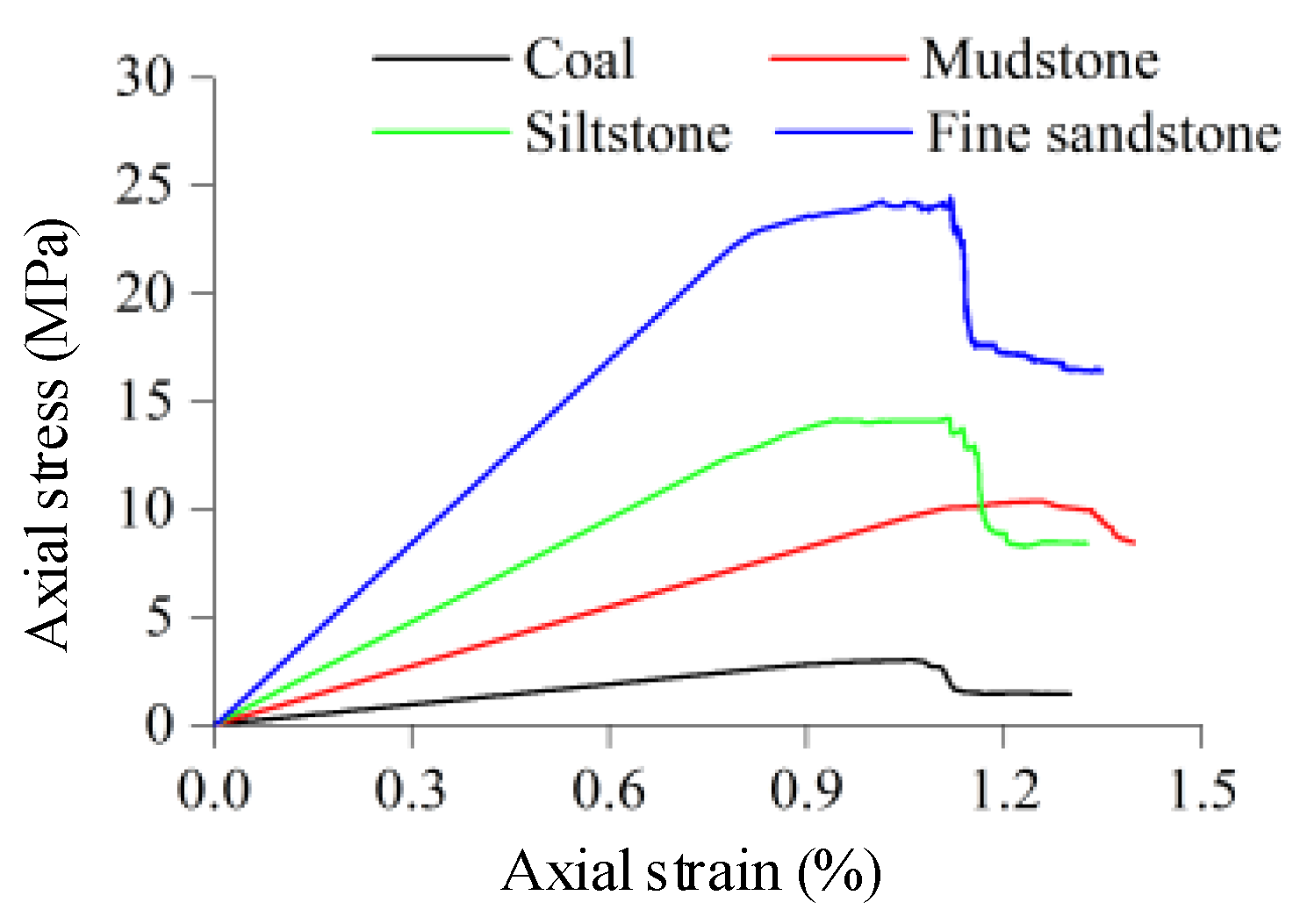
3.3. Parameter Calibration

The microscopic features of the UDEC Trigon blocks and the contacts govern the mechanical behavior of the rock masses. Rock mechanical parameters obtained from the laboratory must be calibrated before applying the numerical models to predict the deformation performance of the rock masses. Firstly, the elastic modulus (Em) of a rock mass was calibrated using the Rock Quality Designation (RQD) measured by field coring and the elastic modulus (Er) of a small specimen (Equation (1)). Afterwards, the ultimate strength of the rock mass was evaluated according to Equation (2), which was found by Singh and Seshagiri Rao [21] through numerous uniaxial compressive strength (UCS) tests. The estimated parameters of rock mass are provided in Table 2.
E m E r = 10 0.0186 RQD 1.91
σ cm σ c = ( E m E r ) p
Then, a 1 m × 2 m model was built to carry out a series of uniaxial compression tests with a loading rate of 0.01 m/s. The properties of the blocks and the contacts were determined based on the method suggested by Gao and Stead [16], as shown in Table 3. The elastic moduli of the blocks were consistent with those of the rock masses. The normal and shear stiffness of the contacts, Kn and Ks were estimated from the following equation [22].
K n = n [ K + ( 4 / 3 ) G Δ Z min ] , 1 n 10
where K and G are bulk and shear moduli, respectively, of the blocks, and ΔZmin is the smallest width of the zone adjacent to the contact in the normal direction.
Thereafter, the contact cohesion and internal friction angle were adjusted to make the peak strength of the specimen consistent with the target value. Figure 7 exhibits the stress-strain curves of the uniaxial compression test results. Regarding the elastic modulus and the peak strength, the error between the calibration value and the target value was less than 6 percent, as can be seen from Table 4.

3.4. Modeling Scheme

The simulation procedure can be divided into three stages:
(1)
Firstly, the model was run to equilibrium after applying the boundary conditions. Rock bolts, anchor cables and chock supports were installed after the excavation of the PRR. In the model, structural “Cable” elements were generated to create the rock bolts and cables, structural “Beam” elements were generated to create the steel ladder beams, and the chock supports were represented by “Support” elements. The parameters of the support system in this paper are shown in Table 5.
(2)
Then, the 31108 panel was excavated. To achieve a thorough understanding of the influence of the mining activities on the coal body deformation of the inby fender in the PRR, a function was defined to monitor the triangular block zone vertical stresses and the break contact length of the inby fender via the UDEC embedded programming language FISH.
(3)
Finally, the inby fender was extracted. When the coal extraction was completed, the variation of triangular block zone horizontal stresses and the proportion of the broken contacts in the roof of the PRR were analyzed.

4. Analysis of Modeling Results

4.1. Deformation of the Inby Fender

Figure 8 shows the failure pattern of the inby fender being 5 m unmined. The vertical stress in the coal in the non-gray area is more than 1.5 times that in the intact rock. The results indicate that macro-structural movement of the fractures in the main roof at different break positions contributes to the differential failure of the coal below.
(1)
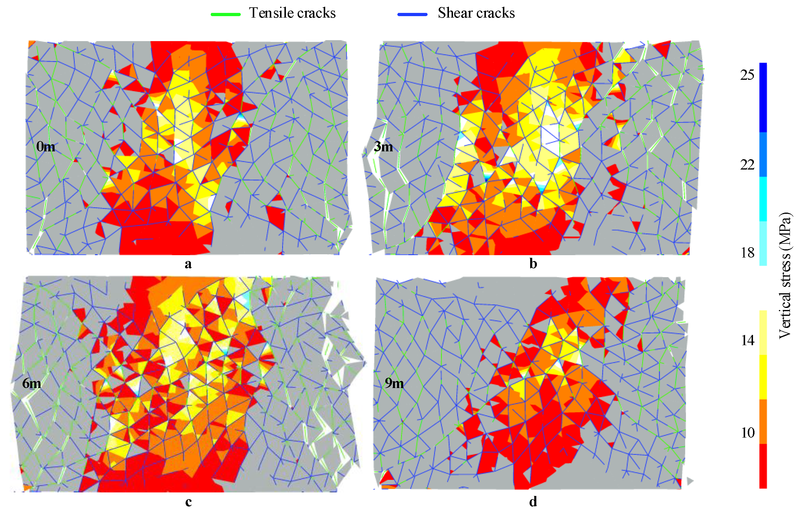
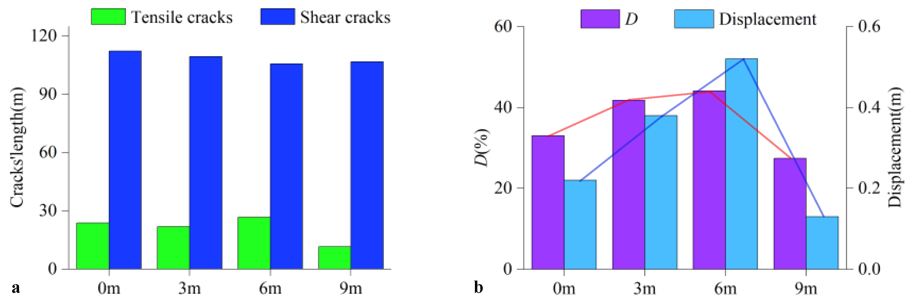
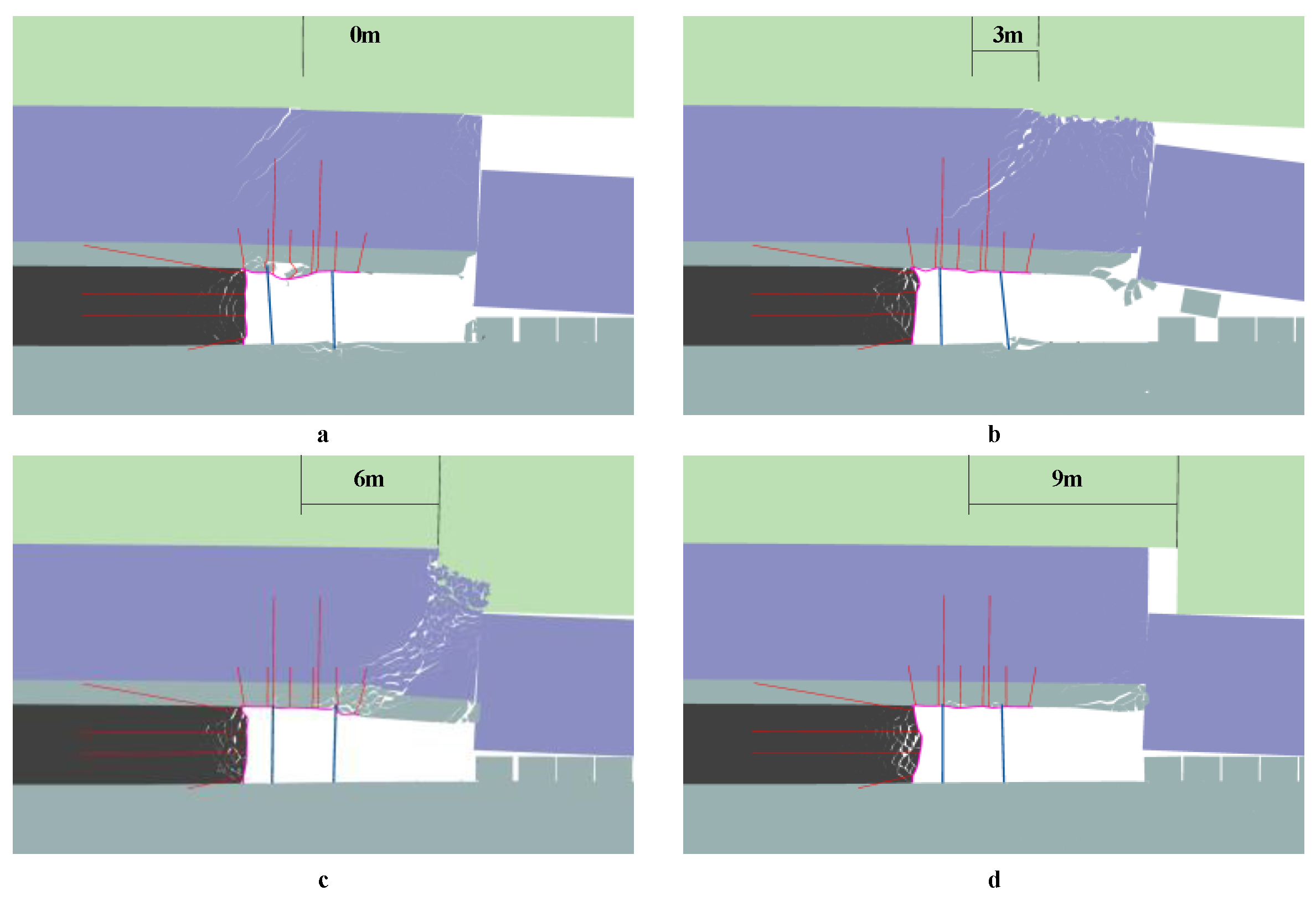
When the break line is above the inby fender, a large area of vertical stress concentration generates in the coal body (Figure 8b,c). According to the statistical results, this area accounts for more than 40% of the fender area, as shown in Figure 9b. However, when the break lines are located above the PRR and the gob (Figure 8a,d), the loads exerted on the coal fender by the fractured blocks decrease significantly.
(2)
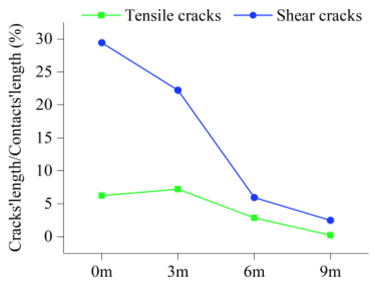
The crack statistics in the coal fender show that there is a small difference in the length of shear cracks under the four conditions, while the length of shear cracks is significantly longer than that of tensile cracks, as illustrated in Figure 9a. The tensile cracks are mainly distributed in the shallow part of the coal pillar. Crack propagation and coalescence result in pillar rib spalling.
(3)
Although there is little difference in the accumulated length of cracks in the four cases, a greater difference exists in the crushing degree at the pillar walls. This is related to the stress concentration degree in the coal fender. As can be seen in Figure 9b, the curves demonstrate that there is a positive correlation between the stress concentration area and the deformation amount at the pillar walls.
(4)
The modeling outcomes indicate that inappropriate estimation of the last weighting position may worsen the coal wall spalling at the longwall face, which is in good agreement with field observations.

4.2. Deformation of the PRR

Figure 10 shows the surrounding rock deformation of the PRR after the panel is extracted. The immediate roof strata are subjected to high deviatoric stresses resulting from the break and subsidence of the main roof, causing the tension cracks to open and extend below the break line. As the cracking area continues to expand with the subsiding of the overburden, roof failure eventually forms due to the development of shear zones in the immediate roof.
When the break lines are 0 m and 3 m away from the center of the PRR, the cables installed in the immediate roof are affected by the tension cracks and break down. Moreover, the supports below suffer from inclination. The simulation results clearly reveal the mechanical response of the PRR while the overburden weighting failure occurs. As can be seen from Figure 10c, although the shear zone in the roof has little impact on the supporting bodies, it is difficult to maintain the roof stability and withdraw the equipment. When the location of the break line is far from the center of the PRR (see Figure 10d), the influence of the deflecting and sinking of the main roof on the development of the shear band inside the immediate roof in the PRR is significantly decreased.

4.3. Roof Cracks and Stresses

Figure 11 presents the horizontal stress curves in the center of the immediate roof above the PRR. After excavating the remaining coal, the vertical stress on one roof side of the PRR is relieved, and the horizontal stress is released by different degrees. However, when the immediate roof is subjected to the shearing action of the main roof and the abutment pillar, horizontal stress concentration takes place in the rock masses near the break line. Accordingly, a macroscopic shear crack zone is formed in the immediate roof. Statistics of fracture distribution in the immediate roof are pictured in Figure 12. The break position approaching the PRR significantly increases the development of shear cracks in the immediate roof.

5. Hydraulic Fracturing

Field practice and simulation results both suggest that the overburden weighting failure more easily occurs when the break position of the main roof is closer to the PRR. As a result, it is necessary to control the break location of the main roof by artificial means so as to reduce the disadvantageous influence of the roof subsidence on the surrounding rocks of the PRR. Destress blasting and hydraulic fracturing can be used to weaken strong roofs to promote the caving of strong hard-to-cave roofs behind the longwall face [23,24,25,26]. However, blasting requires complex operations and strictly limited use of explosives [27,28]. Comparatively, the hydraulic fracturing technique is a more economical way to change the roof structure and has become a significant tool for stratum control in coal mines [29,30,31]. Therefore, hydraulic fracturing was used in this study to deal with the main roof of the 31108 panel.

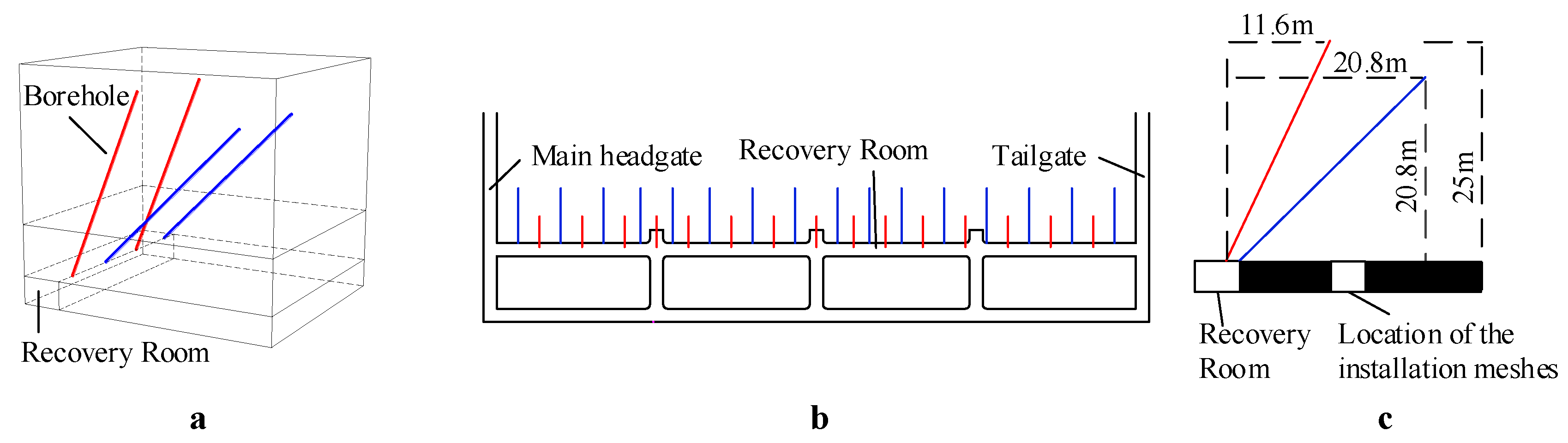
5.1. Borehole Layout

The purpose of hydraulic fracturing was to make the last weighting position of the main roof far away from the PRR and to prevent the occurrence of roof weighting failures. According to in-situ stress conditions and hydraulic fracturing theories, vertical cracks may develop in the fine-grained sandstone of the overlying rocks, facilitating the regular caving of the main roof. To achieve the desired effect, two sets of boreholes were drilled from the roof of the main PRR to the longwall face. The horizontal length of one set of the boreholes was about 20 m, which was determined by the magnitude of the front abutment pressure based on the field tests. The horizontal length of the other set of drilled holes was about 10 m. This was because when the fender width was 10 m, flexible polyester-fiber meshes would be installed to prevent the crushed roof rocks entering the PRR. It was found that hydraulic fracturing could avoid severe subsidence of the panel roof and coal wall spalling during the installation of the cable meshes. The borehole layout is shown in Figure 13. The vertical height of the boreholes was larger than 18.5 m so that the ruptured rocks could fill the gob after fracturing was completed. The spacing of the boreholes was 16 m, the borehole diameter was 65 mm, and the water injection rate was 120 L/min. A high-pressure water pump with a specification of 70 MPa was used for water injection. Fracturing started from the bottom of the boreholes and was performed every 8 m or so in the fine-grained sandstone. The time of each period of fracturing work was maintained at 20–25 min.

5.2. Effect of Hydraulic Fracturing
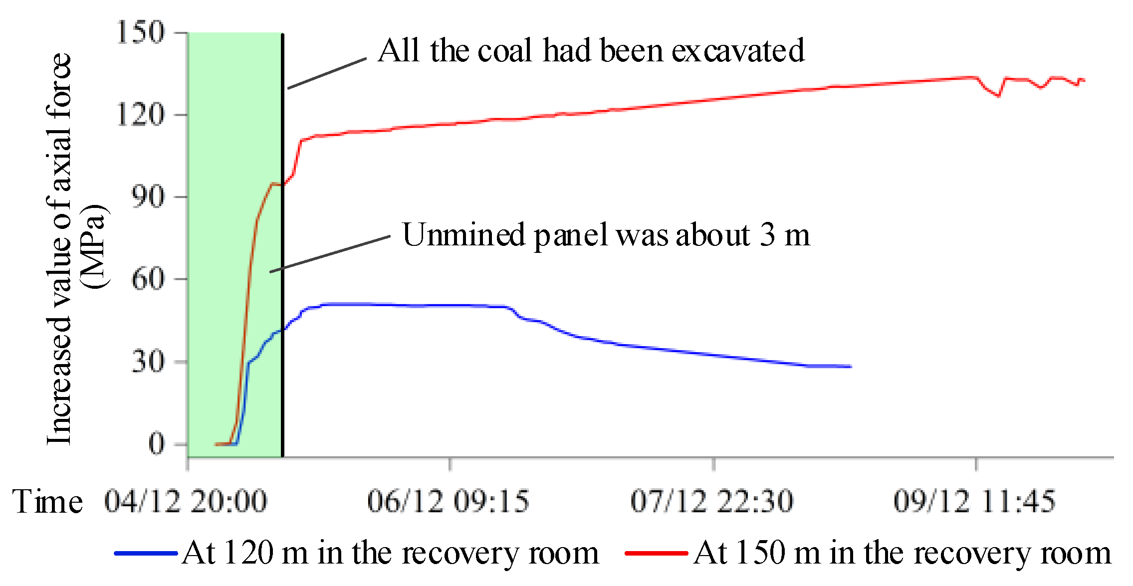
After hydraulic fracturing was finished, electronic dynamometers were employed to monitor the cable’s force on the roof and rib at 120 m and 150 m in the PRR. Meanwhile, instruments were placed to measure the separation amount of the roof rocks in the range of 2 m and 12 m of the PRR. Four sets of instruments were set at 80 m, 120 m, 150 m and 210 m in the PRR, respectively. For analyzing the strength and magnitude of the roof weighting after hydraulic fracturing, the resistance of the supports at the longwall face was collected every 5 min. The monitoring results were as follows:
(1)
When the unmined panel was about 3 m, the stress on the roof cables increased sharply, as shown in Figure 14. At this time, the inby fender started to break and gradually lost its bearing ability. As the roof and floor strata coalesced in the gob, the stress on the roof cables gradually became stable within one day after the entrance of the longwall face to the PRR. The values of the force on the two measuring points were increased by about 50 kN and 133 kN, respectively. The force on the rib cables fluctuated slightly, and the increased value was no more than 10 kN. After hydraulic fracturing, although the stress on the roof cables increased with the transference of the abutment force, the roof remained stable without breaking down and the pillar ribs maintained good stability and bearing capacity.
(2)
The observation results of the four sets of separation instruments found that the separation amount of the roof within 2 to 12 m of the PRR was 0.67 mm, 0.05 mm, 0 mm and 0 mm, respectively. Hydraulic fracturing eliminated the risk of separation and dislocation of the roof strata in the process of mining-induced stress transference.
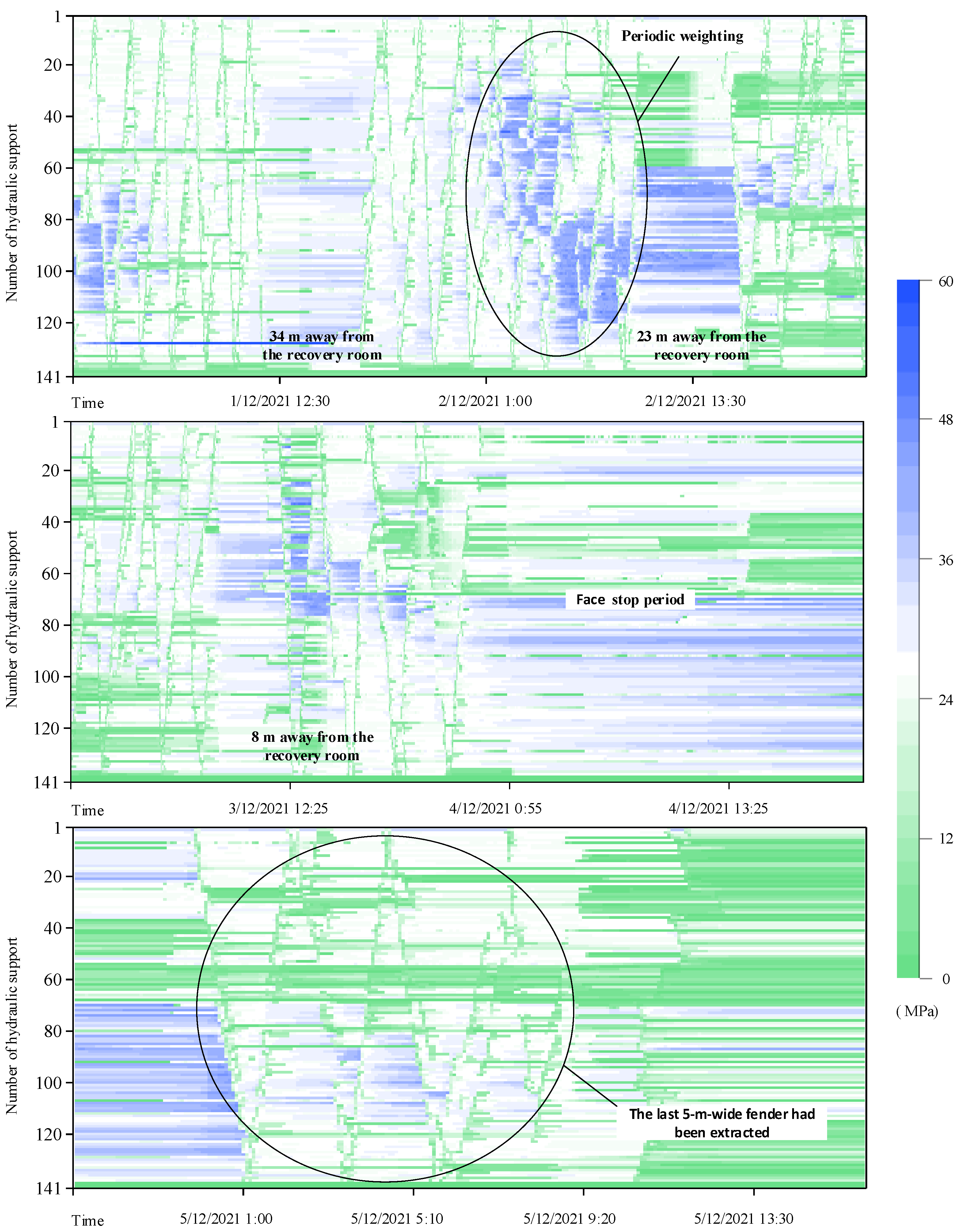
(3)
Figure 15 presents the cloud diagrams of the resistances of the panel supports. At 1:00 a.m. on 1 December 2021, when the PRR and 31108 longwall face were separated by about 30 m, a periodic weighting occurred in the main roof. The stresses on the 30# to 70# supports increased first, and the stresses on the 80# to 120# supports increased later. The weighting step was about 4 m. The average stress on the supports in the weighting area was about 44 MPa. After the longwall face entered the hydraulic fracturing area, extensive stress concentration on the supports did not appear because the gob roof collapsed in time. At 13:00 p.m. on 3 December, when the PRR and 31108 longwall face were separated by about 7–8 m, the stresses on the 23# to 80# supports increased slightly. Compared with the former weighting, the magnitude was smaller and the duration was shorter. In the face stop period (from 0 a.m. on the 4th to 0 a.m. on the 5th), the average stress on the supports was about 31.2 MPa, about 6 MPa higher than the initial stress. During extraction of the last 5-m-wide fender, high stresses on the supports did not appear.
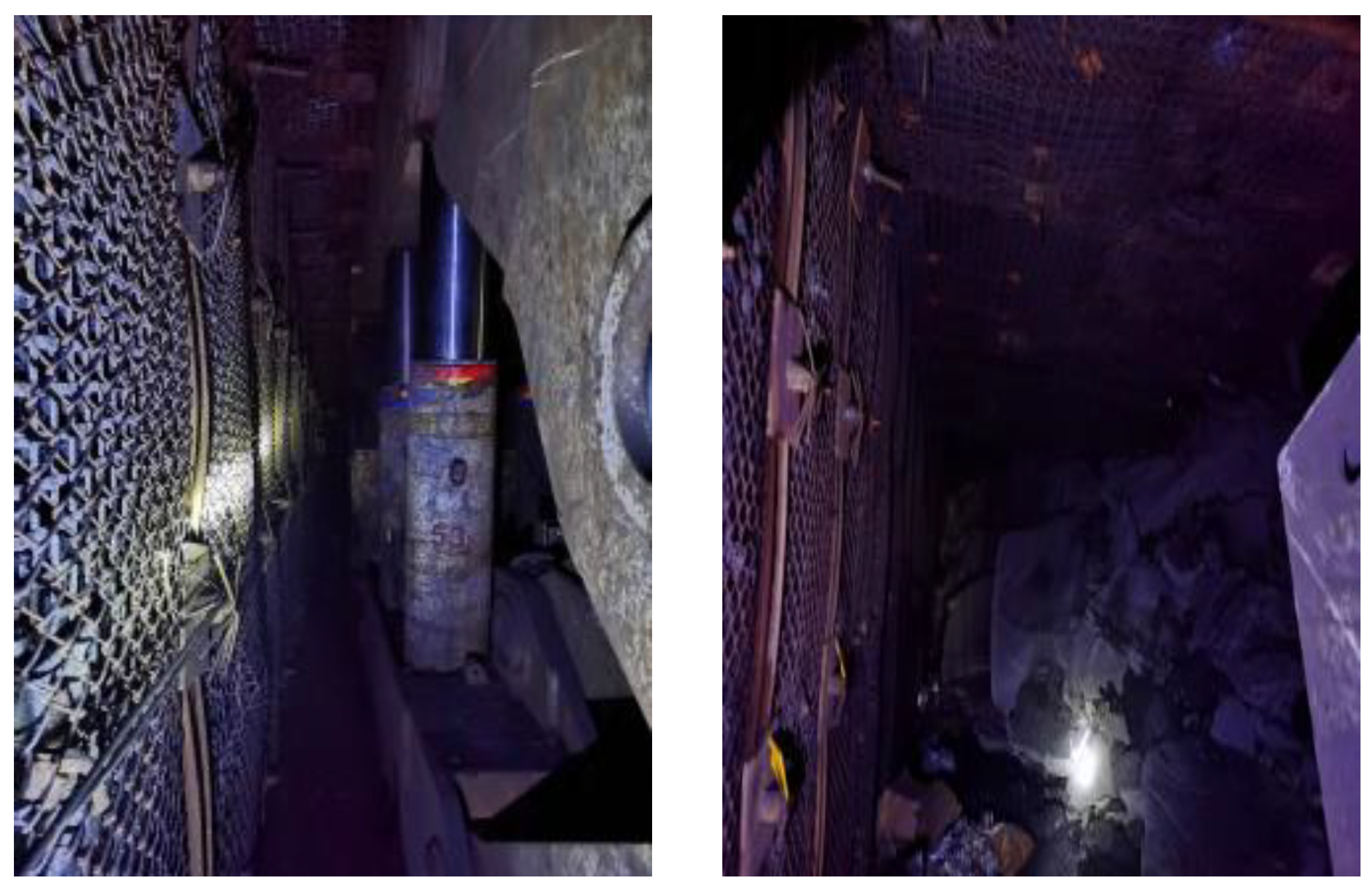
(4)
In the process of withdrawing the equipment, the maximum shrinkage length of the hydraulic supports at the longwall face was 10 cm, and the maximum descending length of the chock supports in the PRR was 6 cm. Good roof stability reduced the difficulty of removing the equipment. Serious damage to the floor was not observed on site. The removal time was reduced by 3 days. Figure 16 is a field photo after hydraulic fracturing.
To sum up, hydraulic fracturing lowered the integrity degree of the overlying strata and reduced the strength of the periodic weighting, thereby completely eliminating the risk of roof weighting failures induced by the movement of the fractured roof rocks.

6. Conclusions

Support-crushing disasters resulting from roof weighting failures in PRR are closely related to the last weighting of the main roof. The break position of the main roof approaching the PRR leads to vertical stress concentration on the inby fender and the coal walls during the longwall face stop period. After the longwall face is completed, subsidence and rotation of the fractured rocks may trigger horizontal stress concentration in the immediate roof and produce a macroscopic shear crack zone. As the cracking area continues to expand with the subsiding of the overburden, roof failure eventually forms due to the development of shear zones in the immediate roof. To mitigate or eliminate these disadvantageous effects, hydraulic fracturing was employed to weaken the main roof strata near the PRR. In the process of withdrawing the equipment, the maximum shrinkage length of the hydraulic supports at the longwall face was 10 cm, and the maximum descending length of the chock supports in the PRR was 6 cm. This significantly reduced the strength of the last weighting, improved the stability of the PRR, and ensured the safety and efficiency of the recovery work of the 31108 panel at Huoluowan Coal Mine. The hydraulic fracturing approach proposed in this investigation provides an effective method of pressure control for coal mines facing roof weighting failures.

Author Contributions

All authors contributed to this paper. Methodology, X.W. and J.B.; validation, G.L.; investigation, Y.Z., F.Z. and M.L.; writing—original draft preparation, G.L.; writing—review and editing, G.L.; funding acquisition, X.W. All authors have read and agreed to the published version of the manuscript.

Funding

This work was supported by the National Key Research and Development Program of China (2020YFB1314204), National Natural Science Foundation of China (Grant No. 52174132), and Joint Funds of the National Natural Science Foundation of China (Grant No. U21A20107).

Data Availability Statement

The data used for conducting classifications are available from the corresponding author upon request.

Conflicts of Interest

The authors declare no potential conflict of interest with respect to the research, authorship, and publication of this article.

References

  1. Tadolini, S.C.; Barczak, T.M. Design parameters of roof support systems for pre-driven longwall recovery rooms. Trans. Soc. Min. Metall. Explor. 2004, 1–13. Available online: https://www.cdc.gov/niosh/mining/works/coversheet939.html (accessed on 17 April 2023).
  2. Kang, H.P.; Lv, H.W.; Zhang, X.; Gao, F.Q.; Wu, Z.G.; Wang, Z.C. Evaluation of the ground response of a pre-driven longwall recovery room supported by concrete cribs. Rock Mech. Rock Eng. 2016, 49, 1025–1040. [Google Scholar] [CrossRef]
  3. Oyler, D.; Frith, R.; Dolinar, D.; Mark, C. International experience with longwall mining into pre-driven rooms. In Proceedings of the 17th International Conference on Ground Control in Mining, Morgantown, WV, USA, 4–6 August 1998; pp. 44–53. [Google Scholar]
  4. Wang, X.Z.; Ju, J.F.; Xu, J.L. Theory and applicable of yield mining at ending stage of fully-mechanized face in shallow seam at shendong mine area. J. Min. Saf. Eng. 2012, 29, 151–156. [Google Scholar]
  5. Wang, B.N.; Dang, F.N.; Chao, W.; Miao, Y.P.; Li, J.; Chen, F. Surrounding rock deformation and stress evolution in pre-driven longwall recovery rooms at the end of mining stage. Int. J. Coal Sci. Technol. 2019, 6, 536–546. [Google Scholar] [CrossRef]
  6. Wang, F.T.; Shao, D.L.; Niu, T.C.; Dou, F.J. Progressive loading characteristics and accumulated damage mechanisms of shallow-buried coal pillars in withdrawal roadways with high-strength mining effect. Chin. J. Rock Mech. Eng. 2022, 41, 1148–1159. [Google Scholar]
  7. Barczak, T.M.; Tadolini, S.C.; Zhang, P. Evaluation of support and ground response as longwall face advances into and widens pre-driven recovery room. In Proceedings of the 26th International Conference on Ground Control in Mining, Morgantown, WV, USA, 31 July–2 August 2007; pp. 160–172. [Google Scholar]
  8. Tadolini, S.C.; Barczak, T.M. Rock mass behavior and support response in a longwall panel pre-driven recovery room. In Proceedings of the 6th International Symposium on Ground Support in Mining and Civil Engineering Construction, Cape Town, South Africa, 30 March–3 April 2008; pp. 167–182. [Google Scholar]
  9. Aghababaei, S.; Saeedi, G.; Jalalifar, H. Risk analysis of roof fall and prediction of damaged regions at retreat longwall coal mining face. Rud. -Geološko-Naft. Zb. 2020, 35, 85–95. [Google Scholar] [CrossRef]
  10. Wang, J.C.; Wang, Z.H.; Tang, Y.S.; Li, M.; Chang, K.L.; Gong, H.; Xu, G.L. Experimental study on mining-induced dynamic impact effect of main roofs in deeply buried thick coal seams with weakly consolidated thin bed rock. Chin. J. Rock Mech. Eng. 2021, 40, 2377–2391. [Google Scholar]
  11. Wang, G.F.; Pang, Y.H. Relationship between hydraulic support and surrounding rock coupling and its application. J. China Coal Soc. 2015, 40, 30–34. [Google Scholar]
  12. Mills, K.W.; Jeffrey, R.G.; Jones, D.W. Successful application of hydraulic fracturing to control windblast hazard at Moonee Colliery. In Proceedings of the 19th International Conference on Ground Control in Mining, Morgantown, WV, USA, 8–10 August 2000; pp. 45–50. [Google Scholar]
  13. Shimada, H.; Mastui, K.; Anwar, H. Control of hard-to-collapse massive roofs in longwall faces using a hydraulic fracturing techniques. In Proceedings of the 17th International Conference on Ground Control in Mining, Morgantown, WV, USA, 4–6 August 1998; pp. 79–87. [Google Scholar]
  14. Wang, X.Z.; Xu, J.L.; Zhu, W.B.; Ju, J.F. Influence of high mining speed on periodic weighting during fully-mechanized mining in a shallow seam. J. China Univ. Min. Technol. 2012, 41, 349–354. [Google Scholar]
  15. Itasca Consulting Group Inc. UDEC (Universal Distinct Element Code), Version 6.0; Itasca: Minneapolis, MN, USA, 2014. [Google Scholar]
  16. Gao, F.Q.; Stead, D. The application of a modified Voronoi logic to brittle fracture modelling at the laboratory and field scale. Int. J. Rock Mech. Min. Sci. 2014, 68, 1–14. [Google Scholar] [CrossRef]
  17. Kazerani, T.; Zhao, J. Micromechanical parameters in bonded particle method for modelling of brittle material failure. Int. J. Numer. Anal. Methods Geomech. 2014, 34, 1877–1895. [Google Scholar] [CrossRef]
  18. Lisjak, A.; Grasselli, G. A review of discrete modeling techniques for fracturing processes in discontinuous rock masses. J. Rock Mech. Geotech. Eng. 2014, 6, 301–314. [Google Scholar] [CrossRef]
  19. Kang, H.P.; Si, L.P.; Zhang, X. Characteristics of underground in-situ stress distribution in shallow coal mines and its applications. J. China Coal Soc. 2016, 41, 1332–1340. [Google Scholar]
  20. Gao, F.Q.; Stead, D.; Kang, H.P. Numerical simulation of squeezing failure in a coal mine roadway due to mining-induced stresses. Rock Mech. Rock Eng. 2015, 48, 1635–1645. [Google Scholar] [CrossRef]
  21. Singh, M.; Seshagiri Rao, K. Empirical methods to estimate the strength of jointed rock masses. Eng. Geol. 2005, 77, 127–137. [Google Scholar] [CrossRef]
  22. Cho, N.; Martin, C.D.; Sego, D.C. A clumped particle model for rock. Int. J. Rock Mech. Min. Sci. 2007, 44, 997–1010. [Google Scholar] [CrossRef]
  23. Konicek, P.; Saharan, M.R.; Mitri, H. Destress blasting in coal mining-state-of-the-art review. Procedia Eng. 2011, 26, 179–194. [Google Scholar] [CrossRef]
  24. Fan, J.; Dou, L.M.; He, H.; Du, T.T.; Zhang, S.B.; Gui, B.; Sun, X.L. Directional hydraulic fracturing to control hard-roof rockburst in coal mines. Int. J. Min. Sci. Technol. 2012, 22, 177–181. [Google Scholar] [CrossRef]
  25. Jeffrey, R.G.; Chen, Z.; Mills, K.W.; Pegg, S. Monitoring and measuring hydraulic fracturing growth during preconditioning of a roof rock over a coal longwall panel. In Proceedings of the ISRM International Conference for Effective and Sustainable Hydraulic Fracturing, Brisbane, QLD, Australia, 20–22 May 2013; pp. 894–914. [Google Scholar]
  26. Kang, H.P.; Jiang, P.F.; Feng, Y.J.; Gao, F.Q.; Zhang, Z.; Liu, X.G. Application of large-scale hydraulic fracturing for reducing mining-induced stress and microseismic events: A comprehensive case study. Rock Mech. Rock Eng. 2023, 56, 1399–1413. [Google Scholar] [CrossRef]
  27. Zhao, K.K. Three-Dimensional Propagation of Hydraulic Fracture from Regional Fracturing in Hard Roof. Ph.D. Thesis, China Coal Research Institute, Beijing, China, 2021. [Google Scholar]
  28. Guo, D.Y.; Lv, P.F.; Zhao, J.C.; Zhang, C. Research progress on permeability improvement mechanisms and technologies of coalbed deep-hole cumulative blasting. Int. J. Coal Sci. Technol. 2020, 7, 329–336. [Google Scholar] [CrossRef]
  29. Huang, B.X.; Wang, Y.Z.; Cao, S.G. Cavability control by hydraulic fracturing for top coal caving in hard thick coal seams. Int. J. Rock Mech. Min. Sci. 2015, 74, 45–57. [Google Scholar] [CrossRef]
  30. Kang, H.P.; Jiang, P.F.; Wu, Y.Z.; Gao, F.Q. A combined “ground support-rock modification-destressing” strategy for 1000-m deep roadways in extreme squeezing ground condition. Int. J. Rock Mech. Min. Sci. 2021, 142, 104746. [Google Scholar] [CrossRef]
  31. Yu, B.; Gao, R.; Kuang, T.J.; Huo, B.J.; Meng, X.B. Engineering study on fracturing high-level hard rock strata by ground hydraulic action. Tunn. Undergr. Space Tech. 2019, 86, 156–164. [Google Scholar] [CrossRef]
Figure 1. Lithology.
Applsci 13 05116 g001
Figure 2. Layout of the PRR.
Applsci 13 05116 g002
Figure 3. Layout plan for the support body of the PRR.
Applsci 13 05116 g003
Figure 4. Spalling of rib in the PRR.
Applsci 13 05116 g004
Figure 5. Break structure of the fine-grained sandstone roof after the longwall panel is completed. (a) the detached block is located in the gob, (b) the detached block is located above the supports, (c) the detached block is located above the recovery room.
Applsci 13 05116 g005
Figure 6. Model overview.
Applsci 13 05116 g006
Figure 7. Stress–strain curve of the UCS tests.
Applsci 13 05116 g007
Figure 8. Comparison of coal pillar failures at different break positions in the main roof (note that the stress concentration coefficient in the non-gray area is greater than 1.5).
Applsci 13 05116 g008
Figure 9. Bar chart of the statistical results (a) Statistical results of crack length. (b) Statistical results of displacement and stress (note that D is the proportion of the area where the stress concentration coefficient is greater than 1.5).
Applsci 13 05116 g009
Figure 10. Deformation of the PRR.
Applsci 13 05116 g010
Figure 11. Horizontal stress curves in the center of the immediate roof.
Applsci 13 05116 g011
Figure 12. Crack proportions in the immediate roof.
Applsci 13 05116 g012
Figure 13. Borehole layout (a) Stereogram (b) Vertical view (c) Side view.
Applsci 13 05116 g013
Figure 14. Axial force increasing curve of anchor cable.
Applsci 13 05116 g014
Figure 15. Distribution of the stresses on the hydraulic supports at the panel.
Applsci 13 05116 g015
Figure 16. Site photos after hydraulic fracturing treatment.
Applsci 13 05116 g016
Table 1. The mechanical behavior of blocks in UDEC Trigon.
In the normal direction
Δσn = −knΔun
Where Δσn and Δun are the effective normal stress increment and normal displacement increment, respectively, and kn is the normal stiffness of the contact.
In the shear direction, if
|τs| ≤ c + σn tanφ = τsmax
then
Δτs = −ksΔuse
or else, if
|τs| ≥ τsmax
then
τs = sign (Δus) τsmax
where φ and c are the cohesion and friction angle of the contact, respectively. Δuse is the elastic component of the incremental shear displacement, and Δus is the total incremental shear displacement.
a. Coulomb friction law [16,17]
Applsci 13 05116 i001
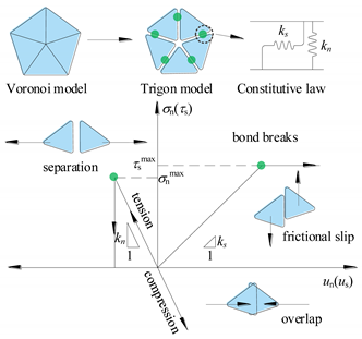
b. Micro-contacts yielding process in Trigon model [17,18]
Table 2. Intact rock parameters and estimated parameters of rock mass in the 31108 panel.
Rock StrataIntact RockRock Quality Designation Rock Mass
Er (GPa)σc (MPa)Em (GPa)σcm (MPa)σtm (MPa)
Coal2.129.66580.312.890.29
Mudstone3.5323.49720.9510.261.03
Siltstone4.0626.72811.6014.881.49
Fine-grained sandstone4.5534.73922.8826.032.60
Table 3. Calibrated micro-properties of triangular blocks and their contacts.
LithologyMatrix PropertiesContact Properties
Density (kg·m−3)E (GPa)Kn (GPa/m)Ks (GPa/m)Cohesion (MPa)Friction (°)Tensile Strength (MPa)
Coal12630.3124.5519.150.91180.23
Mudstone21820.9576.7259.843.27201.00
Limestone22671.60129.21100.784.38201.40
Fine-grained sandstone23582.88243.00189.547.30232.50
Table 4. Calibrated values of Young’s modulus and UCS for rock mass.
LithologyYoung’s Modulus (GPa)UCS (MPa)
TargetCalibratedError (%)TargetCalibratedError (%)
Coal0.310.3172.262.893.045.19
Mudstone0.950.9163.5810.2610.401.36
Siltstone1.601.5920.5014.8814.204.57
Fine-grained sandstone2.882.8202.0826.0324.495.92
Table 5. The parameters of the support system in the PRR.
ElementPropertyValue
CableElastic modulus200 GPa
Stiffness of the grout2 × 109 N/m2
Cohesive capacity of the grout4 × 105 N/m
BeamElastic modulus200 GPa
Tensile yield strength500 MPa
Compressive yield strength500 MPa
Interface normal stiffness10 GPa/m
Interface shear stiffness10 GPa/m
SupportMaximum force at highest loading18,000 kN
Disclaimer/Publisher’s Note: The statements, opinions and data contained in all publications are solely those of the individual author(s) and contributor(s) and not of MDPI and/or the editor(s). MDPI and/or the editor(s) disclaim responsibility for any injury to people or property resulting from any ideas, methods, instructions or products referred to in the content.

