
Revamping Fluid Catalytic Cracking Unit, and Optimizing Catalyst to Process Heavier Feeds

1
LUKOIL Neftohim Burgas, 8104 Burgas, Bulgaria
2
Institute of Biophysics and Biomedical Engineering, Bulgarian Academy of Sciences, 1113 Sofia, Bulgaria
3
Kinetics Technology SpA, 00148 Rome, Italy
*
Author to whom correspondence should be addressed.
Appl. Sci. 2023, 13(3), 2017; https://doi.org/10.3390/app13032017
Submission received: 20 January 2023
/
Revised: 30 January 2023
/
Accepted: 2 February 2023
/
Published: 3 February 2023
(This article belongs to the Special Issue Catalysis in Energy Conversion: Hydrogen Production from Water, CO2 and Biomass Conversion)
Abstract
:H-Oil gas oils have a higher density and higher nitrogen content, and consequently much lower reactivity than straight-run vacuum gas oils during fluid catalytic cracking (FCC). The conversion of H-Oil gas oils observed in a laboratory catalytic cracking unit at constant operating conditions showed a 20 wt.% lower conversion rate than straight-run hydrotreated vacuum gas oil. Thus, a revamp of commercial FCC units, and the selection of a higher activity catalyst with lower coke selectivity is needed to provide the stable trouble-free operation of the unit. The performed revamp of the commercial FCC unit allowed a stable operation at a higher throughput. It also allowed an increased riser outlet temperature from 532 to 550 °C; increased maximum allowable regenerator temperature from 705 to 730 °C; decreased afterburning from 12 to 6 °C; decreased NOx emissions in the flue gas from 250 to 160 mg/Nm3; improved catalyst regeneration; decreased catalyst losses to 0.0142 kg/t feed; and improved catalyst circulation at a higher throughput. It was confirmed in the commercial FCC unit that the H-Oil light vacuum gas oil is the least reactive H-Oil gas oil during catalytic cracking.
1. Introduction
Over the years, fluid catalytic cracking has been extensively used and investigated as the main producer of high octane gasoline [1], middle distillate [2,3,4,5,6], ethylene and propylene [7,8,9,10,11], and bio-fuel [12,13,14,15,16], and as a waste (scrap tire, plastics) processor [17,18,19]. Its flexibility in the processing of feeds with a different quality has allowed the high penetration of FCC technology into petroleum refining. Worldwide, more than 350 FCC units, out of 650 refineries, are operated in petrochemical complexes, converting vacuum gas oil (VGO) and high-boiling residues into lighter fuel products and chemical feedstocks [20]. Now, when mankind has started to replace internal combustion engines with electromobiles and a drop in passenger vehicle production using petrol-based fuel has already been registered [21], the place and meaning of FCC technology as an automotive fuel maker is going to change to it being a chemical producer [22,23]. The most prevalent are the recent studies devoted to the role of FCC as an ethylene and propylene producer [7,8,9,10,11], and bio-fuel producer [11,12,13,14,15,16]. In the next two decades, oil demand for petrochemicals is expected to increase by ca. 4 Mb/d per year, reaching 34% of the total oil market in 2040, in contrast to the current 15% rate [22]. In this respect, FCC technological solutions directed to process whole crude oils have been explored [23,24]. However, the general trend in the extraction of petroleum has been towards heavy and low-quality oil [25,26]. Thus, a combination of FCC and vacuum residue upgrading units seems to best utilize the potential hidden behind the refining of heavy petroleum. The vacuum gas oil generated in the vacuum residue upgrading units can be processed in the FCC unit. Unfortunately, the secondary VGOs coming from cokers or vacuum residue hydrocrackers are characterized by a higher amount of refractory poly-nuclear aromatics and nitrogen compounds [20,27,28,29], which leads to a substantial decrease in the FCC unit conversion. The content of basic nitrogen compounds has an influence on hydrocarbon cracking during the secondary vacuum gas oil (coker and H-Oil VGO) FCC reaction [30,31]. Furthermore, the compositional and structural identification of basic extracts by positive-ion electrospray Fourier-transform ion cyclotron resonance mass spectrometry (FT-ICR MS) shows that basic nitrogen compounds in the secondary vacuum gas oils include N, N2, NO, N2O1, and NS class species [30]. The N1 class species centered at 9 < DBE < 13 with a carbon number ranging from 20 to 24 is the most abundant, and it is a key for coker and H-Oil VGO retarding performance. The effect of the structure and composition of basic nitrogen compounds was found to be much more obvious than that of content, and it was stronger with the increase in their rings plus double-bond equivalence [30]. The secondary vacuum gas oil, nitrogen, determines the ratio between available metal and acid sites of the hydrocracking catalyst. The aromatics generate coke precursors on the available acid sites. Both factors play a coupled role that promotes coke deposition on the catalyst surface, which leads to an increase in the deactivation rate [32]. Thus, both the higher polynuclear aromatic content, and the higher nitrogen content of the coker and H-Oil vacuum gas oils, make them undesirable components of the feed for vacuum gas oil hydrocracking. That is the reason why their processing seems most suitable in fluid catalytic cracking because it is less vulnerable to the higher content of nitrogen and aromatics than fixed-bed vacuum gas oil hydrocracking.
It is a challenge to find the optimum catalyst and operating conditions to maximize conversion during the processing of secondary VGOs [28,33,34]. Another issue when processing secondary vacuum gas oils is the higher coke load of the commercial FCC unit regenerator, which requires more air that can impair cyclone efficiency, and results in higher catalyst losses and poor unit performance [35]. The poor cyclone performance was found to affect catalyst aging that resulted in a lower inventory catalyst activity [35]. All of this was experienced in the LUKOIL Neftohim Burgas FCC unit since it has started processing heavier, more refractory H-Oil vacuum gas oils [36]. That was the reason to revamp the LNB FCCU with the aim of reducing catalyst losses, improving catalyst retention in the reactor–regenerator vessels, increasing catalyst activity, and enhancing conversion by operating at a higher severity during the processing of blends of straight-run and H-Oil vacuum gas oils.
The aim of this article is to discuss how the revamped LNB FCCU improved its performance during the processing of H-Oil gas oils of different quality.
2. Materials and Methods
The properties of the vacuum gas oil feedstock streams (straight-run hydrotreated VGO; H-Oil heavy atmospheric gas oil (HAGO); H-Oil light VGO (LVGO); and H-Oil heavy VGO (HVGO)) feeding the LNB FCCU under study are summarized in Table 1.
Before the revamp, six catalyst candidates were tested in a laboratory FCC unit with the aim of selecting the most active, and least coke-selective catalyst. Figure 1 presents the results of the catalyst tests concerning activity (catalyst-to-oil ratio versus conversion, Figure 1a) and coke selectivity (coke yield versus conversion, Figure 1b).
The properties of the catalyst employed at the LNB FCCU before and after the revamp (catalyst G), and that of the selected, most active and coke-selective catalyst, designated as catalyst H, to employ in the LNB FCCU after the revamp are presented in Table 2.
The conversion was estimated as 100-LCO-HCO-Slurry, wt.%
Where, LCO = light cycle oil yield, wt.%; HCO = heavy cycle oil yield, wt.%; and Slurry = slurry oil yield, wt.%. The main technical and technological problems in the LNB FCCU before the revamp were:
- ➢
- High catalyst losses;
- ➢
- Increased APS of equilibrium catalyst (from 90 to 108 µm). Reduction in the content of the catalyst working fraction (20–80 µm decreasing from 39 to 19%) in the catalyst composition [36];
- ➢
- High temperatures in the regenerator [34];
- ➢
- Shortage of regeneration air;
- ➢
- Unsatisfactory condition of reactor and regenerator lining of internals;
- ➢
- Exhausted service life of internal devices.
- ➢
- Loss of conversion;
- ➢
- Low yields of target products (gasoline, BBF, PPF, LCO);
- ➢
- High olefin content in FCC gasoline;
- ➢
- Increased catalyst Δ coke;
- ➢
- Low catalyst circulation;
- ➢
- Unstable Δp of regenerated and spent catalyst valves at high throughput.
To limit the negative effects of a degraded feedstock quality, the FCCU operated at a load of 240 t/h (design capacity, 250 t/h) [34].
In late 2021, a revamp of the FCCU was carried out, the main objectives of which were:
- ➢
- Adaptation of the FCCU to the processing of heavier vacuum gas oils from H-Oil;
- ➢
- Increasing the mechanical reliability of the equipment by replacing the internal devices in the reactor and regenerator, which were significantly depreciated with expired service life.
- ➢
- Reducing catalyst losses from the reactor and regenerator cyclone systems. Improvement in the environmental situation.
3. Results
3.1. Modifications of the FCC Reactor–Regenerator Section Performed during the Revamp
During the revamp carried out in late 2021, the following scope of modifications was implemented:
For the FCC rector P-201 (Figure 2):
- -
- Replacement of the separator at the end of the riser (VSS = vortex separation system);
- -
- Replacement of riser and reactor inner and outer liner, U-shaped section, and reactor plenum;
- -
- Replacement of feed nozzles;
- -
- Replacement of the cyclone system in the reactor including the upper plenum and the VSS chamber;
- -
- Replacement of the internal components and devices of the reactor stripping section (AF Packing™ was used to fill the reactor section);
- -
- Replacement of the steam distributors which were adapted to the internal devices of the stripper section in the reactor;
- -
- Installation of an isolation gate on the transfer line between the reactor and the main fractionation column in the plant and a new reactor vent valve;
- -
- Replacement of spent and regenerated catalyst transfer lines and installation of new valves to regulate catalyst flow rates between the reactor and regenerator;
- -
- Installation of new instrumentation and adaptation of existing instrumentation.
For regenerator P-202 (Figure 2):
- -
- Replacement of the air distributor;
- -
- Replacement of the regenerator bottom cone;
- -
- Replacement of the cyclone system in the regenerator and installation of a new upper bottom and a new collection chamber;
- -
- Installation of a new distributor for the spent catalyst flowing from the reactor (P-201) into the regenerator (P-202);
- -
- New extraction system for the regenerated catalyst;
- -
- Replacement of liquid fuel injectors (LFI);
- -
- Installation of new instrumentation and adaptation of existing instrumentation.
- -
- Supply and installation of a new air compressor:
- -
- Installation of a new air compressor, CC-202, and connection of the latter to the technological scheme of the installation.
- -
- Construction of a new air line to the spent catalyst distributor in the regenerator.
- -
- Installation of control system for the direct fired air heater (DFAH)-P-201:
- -
- Replacement of the main and pilot burners of the DFAH;
- -
- Installation of new instrumentation and construction of an automatic control system for the combustion process.
3.2. Performance of the FCC Unit before and after the Revamp
The H-Oil gas oils are heavier, with higher aromatic and nitrogen contents, which makes them more difficult to crack, and produce more coke during fluid catalytic cracking than the straight-run hydrotreated vacuum gas oils [38,39]. Table 3 exemplifies the difference in the reactivities of the straight-run VGO and the H-Oil gas oils: HAGO, LVGO, and HVGO obtained on the base of laboratory ACE (advanced cracking equipment) unit operating at 527 °C, with 30 s time on stream, and a catalyst-to-oil ratio = 7.5 wt.
Their quality is a function of the H-Oil reaction temperature, H-Oil throughput, the content of FCC slurry oil (SLO) in the H-Oil feed, and the content of the recycling in the H-Oil feed [40]. The H-Oil LVGO is the most difficult to crack, probably because it has the highest nitrogen content, aromatic carbon content, and lowest Kw-characterization factor (see Table 1) [28,33,41]. The H-Oil HVGO is the most coke-producing gas oil, probably because it contains the highest level of heavy higher-molecular-weight poly-nuclear aromatic hydrocarbons [28,33,41]. The average content of HAGO, LVGO, and HVGO in H-Oil VGO for the 178 studied cases was 19%, 27%, and 54%, respectively, with a variation in HAGO between 5 and 33%; LVGO between 15 and 43%; and HVGO between 36 and 74%. The content of H-Oil VGO in the FCC feed varied between 17 and 37% [39]. As a result of processing, the higher coke made the H-Oil VGO catalyst losses vary between 2.4 and 8.1 t/d before the revamp in 2021, as shown in Figure 3. After the revamp, they fell to 0.9 t/d (Figure 3). The average particle size (APS) of the equilibrium catalyst (E-Cat) increased from 90 to 114 μm from the maintenance turnaround in 2018 until the next turnaround in 2021, which coincided with the FCCU revamp (Figure 4). After the revamp, the APS of E-Cat decreased to the normal level of 90 μm (Figure 4). Having in mind that the catalyst losses affect the content of the working fraction of the catalyst (0–80 μm) and, hence, the catalyst age distribution and activity [35], we decided to compare the LNB FCCU performance at normal catalyst losses before and after the revamp. In this way, the effect of modifications made in the reactor and regenerator section on the FCC unit performance could be evaluated. Table 4 presents data of the operation of the LNB FCCU before and after the revamp.
4. Discussion
4.1. Effects of Performed Revamp on the Operation of the FCC Unit
As a result of the performed revamp of the reactor–regeneration section, the following effects were observed:
- Increasing riser outlet temperature from 540 to 550 °C;
- Increasing maximum allowable regenerator temperature from 705 to 730 °C;
- Decreasing afterburning (ΔT between TRGdilute–TRGdense) from 12 to 6 °C;
- Reduction in NOx emissions in the flue gas from 250 to 160 mg/Nm3;
- Improvement in catalyst regeneration (coke on the regenerated catalyst before revamp = 0.18 wt.%; after revamp = 0.12 wt.%);
- Reduction in catalyst losses from average losses of 4.28 t/d (0.89 kg/t feed) in 2021 before the revamp to 0.85 t/d (0.0142 kg/t feed) in 2022 after the revamp
- Improved catalyst circulation at higher throughput (lower fluctuations in ΔP of regenerated and spent catalyst valves);
Before the revamp in 2021, the LNB FCCU was not in position to run at a capacity higher than 200 t/h because the catalyst losses were increasing linearly with throughput magnification [35], while after the revamp, it ran smoothly and was trouble-free at a capacity of 250 t/h.
4.2. Performance of the FCC Unit before and after the Revamp
By processing the data from the commercial LNB FCCU after the revamp, the variation in the content of H-Oil HAGO, LVGO, and HVGO in the H-Oil VGO blend was as follows:
17.8 wt.% ≤ HAGO ≤ 33.2 wt.%; 19.7 wt.% ≤ LVGO ≤ 37.5 wt.%; 36.1 wt.% ≤ LVGO ≤ 57.2 wt.%; and the H-Oil VGO blend content in the FCC feed varied between 15.7 wt.% and 34.5 wt.%. The following multiple regression was developed:
Figure 5 shows the parity graph of the estimated versus observed conversion. This data shows a very good agreement between observed conversion and that predicted by Equation (1), keeping in mind that this is commercial data, where the noise of the data is relatively high. Equation (1) indicates that the commercial FCCU data confirms the H-Oil gas oil reactivity data (see the data in Table 3) obtained in the laboratory ACE unit, showing that the least reactive H-Oil gas oil is LVGO. The data in Table 3, and that shown in Figure 1, suggest that the most appropriate catalyst to process the heavier gas oils from H-Oil is that possessing both the highest activity and the lowest coke selectivity.
The data in Table 4 shows that the H-Oil VGO suppresses hydrogenation in the FCC feed hydrotreater (pretreater = FCCPT). This is evident from the lower density reduction in the hydrotreated VGO (9 kg/m3 at 8.9% H-Oil VGO content in the FCCPT feed) than that during processing only straight-run VGO (21 kg/m3 at zero content of H-Oil VGO in the FCCPT feed). The data in Table 4 also indicate that the quality and quantity of the H-Oil VGO in the FCC feed for the three studied cases are different. The highest share in the FCC feed and the lowest Kw-characterization factor of the H-Oil VGO was observed for Case: 11–13 September 2022 (after FCC revamp). The FCC feed for this case was also characterized by the lowest Kw-characterization factor. This means that the feed for this case is the most refractory among the studied three cases. Considering the relation of FCC feed containing H-Oil VGO established in our earlier research [28] and shown in Equation (2):
The estimated conversions which reflect FCC feed reactivity are as follows:
- -
- Case: 10 September –11 September 2018 (before revamp) = 71.2 wt.% estimated conversion;
- -
- Case: 11 September –13 September 2022 (after revamp) = 67.3 wt.% estimated conversion;
- -
- Case 2.10–3.10.2022 (after revamp) = 70.4 wt.% estimated conversion.
These data suggest that Case: 11 September –13 September 2022 (after revamp) has the lowest reactivity feed, while the other two cases have the same reactivity feeds (the difference between estimated conversions is 1.1%, which is lower than the error of prediction of Equation (2)). Despite the poor quality of the feed for the Case: 11 September –13 September 2022 (after the revamp), it demonstrated the same conversion level as that observed in Case: 10 September –11 September 2018 (before revamp). Comparing the cases which have the same quality of FCC feed, Case: 10 September –11 September 2018 (before the revamp) and Case 2.10–3.10.2022 (after the revamp), one can see that the case after the revamp registered a 2.5 wt.% higher conversion. Another big advantage of the revamp is the higher octane number of the gasoline (+0.8 points for both RON and MON).
Concerning the olefinicity of the PPF and BBF, the revamp does not affect it, showing the same propylene content in the PPF, and the same content of C4 olefins in the BBF.
The quality of the E-Cat after the revamp in terms of micro-activity shows stabilization with a slight tendency to increase from 73.4 to 74.5% with the replacement of the lower-activity catalyst G with the higher-activity catalyst H (Figure 6). Before the revamp the micro-activity of E-Cat varied across a very wide range (between 61 and 76%), which was caused by the higher catalyst losses, and the resulting higher catalyst addition rate, and the retention in the inventory of the more aged catalyst with a lower content of the working fraction 0–80 μm.
5. Conclusions
The processing of heavier H-Oil gas oils in FCC is associated with conversion reduction and coke-made augmentation. Thus, a higher activity catalyst with lower coke selectivity can deliver a higher conversion of feeds containing H-Oil gas oils. The finding that H-Oil LVGO is the least reactive H-Oil gas oil observed in a laboratory FCC ACE unit was confirmed during processing of the H-Oil VGO blend consisting of HAGO, LVGO, and HVGO in the commercial FCCU.
The revamp of the LNB FCCU performed in late 2021 allowed an increase in riser outlet temperature from 532 to 550 °C; an increase in maximum allowable regenerator temperature from 705 to 730 °C; a decrease in afterburning from 12 to 6 °C; a decrease in NOx emissions in the flue gas from 250 to 160 mg/Nm3; an improvement in catalyst regeneration; a decrease in catalyst losses to 0.0142 kg/t of feed; and improved catalyst circulation at a higher throughput.
The experience gained during the processing of H-Oil gas oils in both laboratory and commercial FCC units has shown that a commercial FCC unit which is intended to process H-Oil vacuum gas oils with different quantity and quality badly needs a revamp. The revamp should consist of modifications of internal parts in both the reactor and regenerator to guarantee good catalyst regeneration, retention in the inventory, and higher catalyst circulation, to provide a higher vacuum gas oil conversion. A future investigation in this area is directed to increasing the propylene yield by selecting a proper catalyst and additives, and the modification of the main fractionator and vapor recovery unit while processing feeds containing H-Oil gas oils.
Author Contributions
Conceptualization, D.S. and I.C.; methodology, D.S. and M.I.; software, G.S.; validation, G.A.; formal analysis, M.I.; investigation, M.I. and G.S.; resources, I.C.; data curation, G.A.; writing—original draft preparation, D.S.; writing—review and editing, D.S.; supervision, I.C. and G.S.; project administration, I.C. All authors have read and agreed to the published version of the manuscript.
Funding
This research received no external funding.
Institutional Review Board Statement
Not applicable.
Informed Consent Statement
Not applicable.
Data Availability Statement
Not applicable.
Conflicts of Interest
The authors declare no conflict of interest.
Nomenclature
| ACE | Advanced cracking evaluation |
| APS | Average particle size of FCC catalyst |
| BBF | Butane-butylene fraction |
| C2- | Yield of dry gas, wt.% |
| C3 | Yield of propane-propylene fraction, wt.% |
| C3= | Propylene |
| C4= | Butylenes |
| C4 | Yield of butane-butylene fraction, wt.% |
| CTO | Catalyst-to-oil ratio, wt./wt. |
| DHAH | Direct heating air heater |
| E-Cat | Equilibrium catalyst |
| FBP | Final boiling point |
| FCC | Fluid catalytic cracking |
| FCCPT | Fluid catalytic cracking pretreater (feed hydrotreater) |
| FCCU | Fluid catalytic cracking unit |
| HAGO | Heavy atmospheric gas oil |
| HCO | Heavy cycle oil |
| HTVGO | Hydrotreated vacuum gas oil |
| HVGO | Heavy vacuum gas oil |
| IBP | Initial boiling point |
| iC4= | Iso-butylene |
| iC4 | Iso-butane |
| Kw | Characterization Watson factor |
| LCO | Light cycle oil |
| LFI | Liquid fuel injector |
| LNB | LUKOIL Neftohim Burgas |
| LVGO | Light vacuum gas oil |
| MON | Motor octane number |
| PPF | Propane-propylene fraction |
| RON | Research octane number |
| RVP | Reid vapour pressure |
| SRHTVGO | Straight-run hydrotreated vacuum gas oil |
| TOS | Time on stream |
| VGO | Vacuum gas oil |
References
- Kegerreis, C.K.; Schweizer, A.E.; Welch, R.C.; Croela, J.; Wood-Black, F.K. The Fluid Bed Reactor; American Chemical Society, Division of the History of Chemistry and The Office of Communications: Baton Rouge, LA, USA, 1998. [Google Scholar]
- Corma, A.; Sauvanaud, L. Improving LCO yield and quality in FCC units: Cracking pathways analysis. In Fluid Catalytic Cracking VII: Materials. Methods and Process Innovations; Occelli, M., Ed.; Elsevier Science: Atlanta, GA, USA, 2007; pp. 41–54. [Google Scholar]
- Hunt, D.; Hu, R.; Ma, H.; Langan, L.; Cheng, W. Strategies for increasing production of light cycle oil. Pet. Technol. Q. 2009, 14, 71–89. [Google Scholar]
- Melin, M.; Baillie, C. Maximum operations. Hydrocarb. Eng. 2009, 14, 29–34. [Google Scholar]
- Stratiev, D.; Shishkova, I.; Obryvalina, A.; Telyashev, R. Feed properties impact on the fluid catalytic cracking unit—Key issues in a diesel market. Oil Gas Eur. Mag. 2011, 36, 25–28. [Google Scholar]
- Niccum, P.K. Diesel creation in the FCC centered refinery. In Proceedings of the Coking & CatCracking Conference, Galveston, TX, USA, 8–10 May 2013. [Google Scholar]
- Yakubu, J.M.; Patel, R.; Mujtaba, I.M. Maximization of propylene in an industrial FCC unit. Appl. Petrochem. Res. 2018, 8, 79–95. [Google Scholar]
- Singh, U.; Ziebarth, M.; Roberie, T.; Cheng, W.C.; Knöll, J.; Fougret, C.; Brandt, S.; Nicolich, J. Advances in propylene maximization from the FCC unit. Catalagram 2014, 115, 6–12. [Google Scholar]
- De Graaf, B.; Allahverdi, M.; Evans, M.; Diddams, P. ‘Snakes and ladders’ for maximising propylene. PTQ 2014, Q4, 1–7. [Google Scholar]
- Tian, Y.; Che, Y.; Chen, M.; Feng, W.; Zhang, J.; Qiao, Y. Catalytic upgrading of vacuum residue-derived cracking gas-oil for maximum light olefin production in a combination of a fluidized bed and fixed bed reactor. Energy Fuels 2019, 33, 7297–7304. [Google Scholar] [CrossRef]
- Zhu, X.; Yu, M.; Cheng, M.; Wang, Y.; Zhang, H.; Wang, G.; Li, C. Conceptual fluid catalytic cracking process with the additional regenerated catalyst circulation path for gasoline reprocessing and upgrading with minimum loss. Energy Fuels 2020, 34, 235–244. [Google Scholar] [CrossRef]
- Bertero, M.; Garcia, J.R.; Falco, M.; Sedran, U. Hydrocarbons from bio-oils: Performance of the matrix in FCC Catalysts in the immediate catalytic upgrading of different raw bio-oils. Waste Biomass Valorization 2017, 8, 933–948. [Google Scholar] [CrossRef]
- Al Jamri, M.; Li, J.; Smith, R. Molecular modelling of co-processing biomass fast pyrolysis oil in fluid catalytic cracking unit. Ind. Eng. Chem. Res. 2020, 59, 1989–2004. [Google Scholar] [CrossRef]
- Ochoa, A.; Vicente, H.; Sierra, I.; Arandes, J.M.; Castaño, P. Implications of feeding or co-feeding bio-oil in the fluid catalytic cracker (FCC) in terms of regeneration kinetics and energy balance. Energy 2020, 209, 118467. [Google Scholar] [CrossRef]
- Vu, X.H.; Nguyen, S.; Dang, T.T.; Armbruster, U. Improved biofuel quality in catalytic cracking of triglyceride-rich biomass over nanocrystalline and hierarchical ZSM-5 catalysts. Biomass Convers. Biorefin. 2021, 11, 755–766. [Google Scholar] [CrossRef]
- Eschenbacher, A.; Myrstad, T.; Bech, N.; Thi, H.D.; Auersvald, M.; Van Geem, K.M.; Jensen, A.D. Fluid catalytic co-processing of bio-oils with petroleum intermediates: Comparison of vapour phase low pressure hydrotreating and catalytic cracking as pretreatment. Fuel 2021, 302, 121198. [Google Scholar] [CrossRef]
- Rodríguez, E.; Gutiérrez, A.; Palos, R.; Azkoiti, M.J.; Arandes, J.M.; Bilbao, J. Cracking of scrap tires pyrolysis oil in a fluidized bed reactor under catalytic cracking unit conditions. Effects of operating conditions. Energy Fuels 2019, 33, 3133–3143. [Google Scholar] [CrossRef]
- Rodríguez, E.; Palos, R.; Gutiérrez, A.; Arandes, J.M.; Bilbao, J. Scrap tires pyrolysis oil as a co-feeding stream on the catalytic cracking of vacuum gasoil under fluid catalytic cracking conditions. J. Waste Manag. 2020, 105, 18–26. [Google Scholar] [CrossRef] [PubMed]
- Knaus, F.; Lutz, H.; Büchele, M.; Reichhold, A.; Pazos-Costa, A. Municipal plastic waste recycling in fluid catalytic cracking units: Production of petrochemicals and fuel in an fluid catalytic cracking pilot plant from biogenic and recycled feedstocks. Chem. Eng. Process. Process Intensif. 2022, 182, 109204. [Google Scholar] [CrossRef]
- Li, Z.; Wang, G.; Liu, Y.; Gao, J.; Xu, C.; Liang, Y.; Wang, X. Study on reaction performance and competitive adsorption effect during coker gas oil catalytic cracking. Fuel Process. Technol. 2013, 115, 1–10. [Google Scholar] [CrossRef]
- Greencarcongress.com. Adamas. China Rare Earth Consumption for Catalytic Converters Down on Weak Passenger Vehicle Production. Available online: https://www.greencarcongress.com/2019/08/20190807-admas.html (accessed on 7 August 2019).
- Alabdullah, M.A.; Gomez, A.R.; Vittenet, J.; Bendjeriou-Sedjerari, A.; Xu, W.; Abba, I.A.; Gascon, J. A viewpoint on the refinery of the future: Catalyst and process challenges. ACS Catal. 2020, 10, 8131–8140. [Google Scholar] [CrossRef]
- Corma, A.; Corresa, E.; Mathieu, Y.; Sauvanaud, L.; Al-Bogami, S.; Al-Ghrami, M.S.; Bourane, A. Crude oil to chemicals: Light olefins from crude oil. Catal. Sci. Technol. 2017, 7, 12–46. [Google Scholar] [CrossRef]
- Al-Khattaf, S.; Saeed, M.R.; Aitani, A.; Klein, M.T. Catalytic cracking of light crude oil to light olefins and naphtha over ECat and MFI: MAT versus ACE and effect of high reaction temperature. Energy Fuels 2018, 32, 6189–6199. [Google Scholar] [CrossRef]
- Dittmeyer, R.; Klumpp, M.; Kant, P.; Ozin, G. Crowd oil not crude oil. Nat. Commun. 2019, 10, 1818. [Google Scholar] [CrossRef] [PubMed]
- Liu, Y.; Lu, S.; Yan, X.; Gao, S.; Cui, X.; Cui, Z. Life cycle assessment of petroleum refining process: A case study in China. J. Clean. Prod. 2020, 256, 120422. [Google Scholar] [CrossRef]
- Li, Z.; Wang, G.; Gao, J. Effect of retarding components on heavy oil catalytic cracking and their corresponding countermeasures. Energy Fuels 2019, 33, 10833–10843. [Google Scholar] [CrossRef]
- Stratiev, D.; Shishkova, I.; Ivanov, M.; Dinkov, R.; Georgiev, B.; Argirov, G.; Atanassova, V.; Vassilev, P.; Atanassov, K.; Yordanov, D.; et al. Catalytic cracking of diverse vacuum residue hydrocracking gas oils. Chem. Eng. Technol. 2021, 44, 997–1008. [Google Scholar] [CrossRef]
- Jia, B.; Xian, C.; Tsau, J.-S.; Zuo, X.; Jia, W. Status and outlook of oil field chemistry-assisted analysis during the energy transition period. Energy Fuels 2022, 36, 12917–12945. [Google Scholar] [CrossRef]
- Li, Z.; Wang, G.; Shi, Q.; Xu, C.; Gao, J. Retardation effect of basic nitrogen compounds on hydrocarbons catalytic cracking in coker gas oil and their structural identification. Ind. Eng. Chem. Res. 2011, 50, 4123–4132. [Google Scholar] [CrossRef]
- Yankov, V. Dependence of Performance of Processes “Vacuum Residue Hydrocracking H-Oil”, and “Fluid Catalytic Cracking of Vacuum Gas Oil” on Feedstock Properties, and Severity of Operation in H-Oil. Ph.D. Thesis, University Prof. Dr. Assen Zlatarov, Burgas, Bulgaria, 13 January 2023. [Google Scholar]
- Vivas-Báez, J.C.; Pirngruber, G.D.; Servia, A.; Dubreuil, A.-C.; Pérez-Martínez, D.J. Impact of Feedstock Properties on the Deactivation of a Vacuum Gas Oil Hydrocracking Catalyst. Energy Fuels 2021, 35, 12297–12309. [Google Scholar] [CrossRef]
- Stratiev, D.; Shishkova, I.; Ivanov, M.; Dinkov, R.; Georgiev, B.; Argirov, G.; Atanassova, V.; Vassilev, P.; Atanassov, K.; Yordanov, D.; et al. Role of Catalyst in Optimizing Fluid Catalytic Cracking Performance during Cracking of H-Oil-Derived Gas Oils. ACS Omega 2021, 6, 7626–7637. [Google Scholar] [CrossRef]
- Stratiev, D.; Shishkova, I.; Ivanov, M.; Chavdarov, I.; Yordanov, D. Dependence of Fluid Catalytic Cracking Unit Performance on H-Oil Severity, Catalyst Activity, and Coke Selectivity. Chem. Eng. Technol. 2020, 43, 2266–2276. [Google Scholar] [CrossRef]
- Stratiev, D.S.; Ivanov, M.; Shishkova, I.; Dinkov, R.; Petrov, I. Commercial FCC experience with processing blends of straight run hydrotreated VGO and H-Oil VGO and employing different catalysts. Oil Gas Eur. Mag. 2021, 4, 20–27. [Google Scholar]
- Stratiev, D.; Shishkova, I.; Dinkov, R.; Dobrev, D.; Argirov, G.; Yordanov, D. The Synergy between Ebullated Bed Vacuum Residue Hydrocracking and Fluid Catalytic Cracking Processes in Modern Refining—Commercial Experience; Prof. Marin Drinov Publishing House of Bulgarian Academy of Sciences: Sofia, Bulgaria, 2022. [Google Scholar]
- Stratiev, D.; Shishkova, I.; Ivanov, M.; Dinkov, R.; Argirov, G.; Vassilev, S.; Yordanov, D. Validation of Diesel Fraction Content in Heavy Oils Measured by High Temperature Simulated Distillation and Physical Vacuum Distillation by Performance of Commercial Distillation Test and Process Simulation. Appl. Sci. 2022, 12, 11824. [Google Scholar] [CrossRef]
- Stratiev, D.; Shishkova, I.; Petrov, I.; Yordanov, D.; Toteva, V. Petroleum crude slate, catalyst properties and H-Oil VGO properties effects on a commercial FCC unit performance. J. Chem. Technol. Metall. 2021, 56, 488–498. [Google Scholar]
- Stratiev, D.; Shishkova, I.; Ivanov, M.; Petrov, I.; Atanassova, V.; Ribagin, S.; Atanassov, K.; Toteva, V.; Stratiev, D. Commercial and laboratory experience with catalytic cracking of straight run hydrotreated vacuum gas oil and H-Oil gas oils. J. Chem. Technol. Metall. 2022, 57, 215–223. [Google Scholar]
- Stratiev, D.S.; Shishkova, I.K.; Dinkov, R.K.; Petrov, I.P.; Kolev, I.V.; Yordanov, D.; Sotirov, S.; Sotirova, E.; Atanassova, V.; Ribagin, S.; et al. Crude Slate, FCC slurry oil, Recycle, and Operating Conditions Effects on H-Oil product quality. Processes 2021, 9, 952. [Google Scholar] [CrossRef]
- Stratiev, D.; Shishkova, I.; Yankov, V.; Kolev, I.; Mitkova, M. Impact of H-Oil vacuum residue hydrocracking severity on fluid catalytic cracking unit performance. Petrol. Sci. Technol. 2020, 38, 565–573. [Google Scholar] [CrossRef]
Figure 1.
Laboratory tests with six catalyst candidates to select the most active (a) and coke selective (b) catalyst to employ in the revamped FCC unit.
Figure 1.
Laboratory tests with six catalyst candidates to select the most active (a) and coke selective (b) catalyst to employ in the revamped FCC unit.
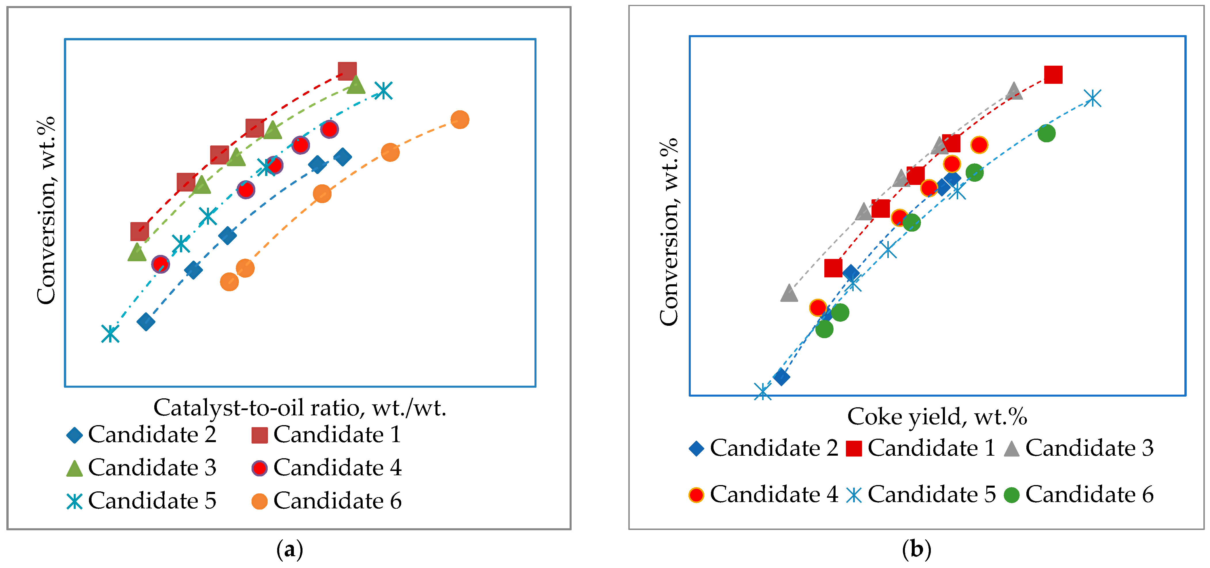
Figure 2.
A diagram of reactor–regenerator section of the FCC unit, whose parts shown with inscriptions were revamped.
Figure 2.
A diagram of reactor–regenerator section of the FCC unit, whose parts shown with inscriptions were revamped.
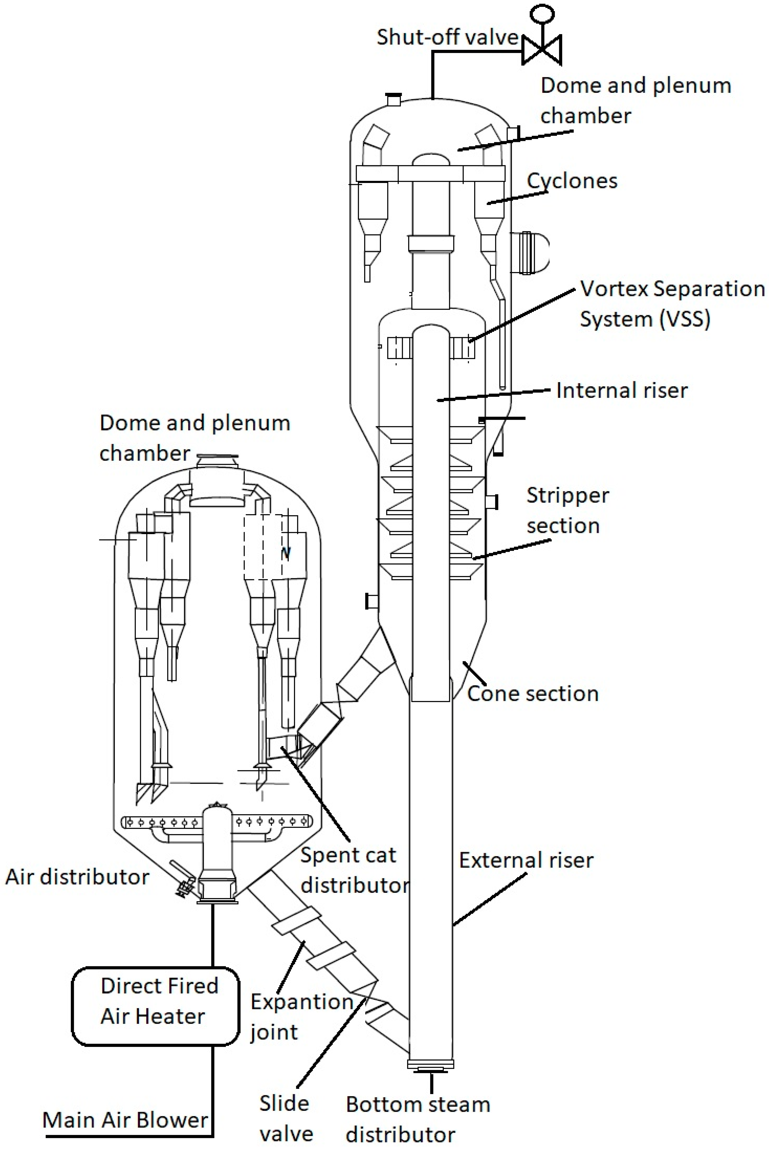
Figure 3.
Variation in catalyst losses before and after the revamp of the LNB FCCU.
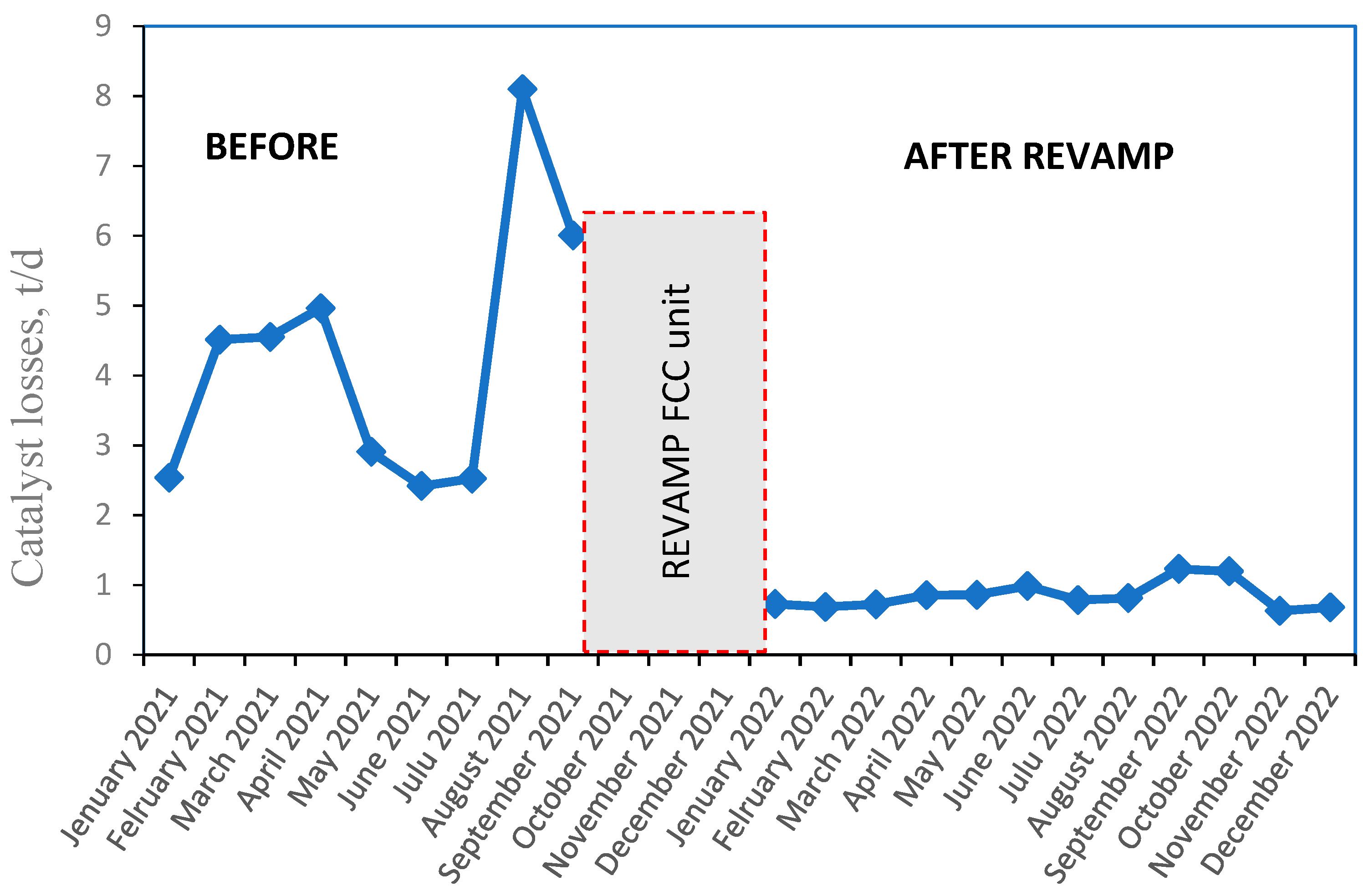
Figure 4.
Variation in average particle size (APS) of E-Cat before and after the revamp.
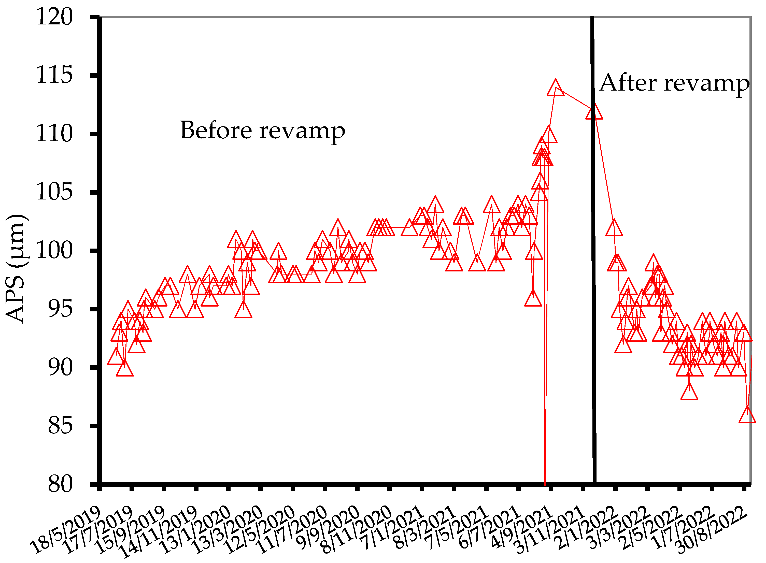
Figure 5.
Parity graph of conversion estimated by Equation (1) versus observed conversion at the LNB FCCU.
Figure 5.
Parity graph of conversion estimated by Equation (1) versus observed conversion at the LNB FCCU.

Figure 6.
Micro-activity of E-Cat variation in time before and after the revamp.


Table 1.
Properties of the FCC feed streams studied in this work.
| FCC Feed Properties | Methods | SRHTVGO | H-Oil HVGO | H-Oil LVGO | H-Oil HAGO |
|---|---|---|---|---|---|
| Density at 15 °C, g/cm3 | ASTM D 4052 | 0.9014 | 0.9784 | 0.9639 | 0.9393 |
| Sulphur, wt.% | ASTM D 4294 | 0.1763 | 0.67 | 0.48 | 0.37 |
| Nitrogen, wt.% | ASTM D 5762 | 0.08 | 0.25 | 0.32 | 0.21 |
| Basic nitrogen, mg/kg | UOP269 | 393 | 819 | 1070 | 686 |
| Conradson carbon, wt.% | ASTM D 189 | 0.24 | 2.67 | 0.34 | 0.15 |
| Refractive Index, 60 °C | ASTM D 1747 | 1.499 | 1.551 | 1.540 | 1.521 |
| C_Aromatics, wt.% | ASTM D3238 | 24.4 | 41.3 | 43.6 | 38.7 |
| C_Paraffins, wt.% | ASTM D3238 | 60.1 | 48.6 | 47.6 | 50.7 |
| C_Naphthenes, wt.% | ASTM D3238 | 15.5 | 10.1 | 8.9 | 10.7 |
| Molecular Weight, g/mol | VPO | 396 | 416 | 323 | 296 |
| Sim. Dist., °C | ASTM D 2887-extended | ||||
| IBP | 287 | 213 | 254 | 234 | |
| 5% wt. | 353 | 395 | 316 | 300 | |
| 10% wt. | 371 | 416 | 336 | 322 | |
| 50%wt. | 444 | 484 | 403 | 373 | |
| 90% wt. | 529 | 541 | 479 | 433 | |
| 95% wt. | 556 | 556 | 503 | 455 | |
| FBP | 595 | 555 | 517 | ||
| Kw-factor | 12.10 | 11.61 | 11.48 | 11.53 |
Table 2.
Properties of the FCC catalyst employed in the commercial LNB FCC unit during this study.
| The Period of Using the Catalyst at the LNB FCCU | 2021–August 2022 (before and after the Revamp) | After August 2022 (after the Revamp) |
|---|---|---|
| Catalyst G | Catalyst H | |
| Fresh catalyst properties | ||
| Total surface area, m2/g | 298 | 288 |
| Na2O, % | 0.30 | 0.29 |
| RE2O3, % | 2.8 | 3.2 |
| Al2O3, % | 42.0 | 42.0 |
| APS, μ | 86 | 76 |
| ABD, g/cm3 | 0.72 | 0.72 |
| Microactivity, % | 81 | 83 |
| Equilibrium catalyst properties | ||
| Total surface area, m2/g | 152 | 150 |
| Na2O, % | 0.21 | 0.19 |
| RE2O3, % | 2.60 | 3.06 |
| Al2O3, % | 45.4 | 44.8 |
| APS, μm | 91 | 91 |
| ABD, g/cm3 | 0.88 | 0.85 |
| Unit cell size, Å | 24.31 | 24.32 |
| Microactivity, % | 73.4 | 74.5 |
| Coke factor | 0.84 | 0.76 |
| Ni, ppm | 120 | 103 |
| V, ppm | 342 | 265 |
Table 3.
Conversion of SRHTVGO, H-Oil HAGO, LVGO, and HVGO obtained in a laboratory ACE unit during the use of catalyst G. The quality of the cracked gas oils was identical to that shown in Table 1.
Table 3.
Conversion of SRHTVGO, H-Oil HAGO, LVGO, and HVGO obtained in a laboratory ACE unit during the use of catalyst G. The quality of the cracked gas oils was identical to that shown in Table 1.
| Gas Oils | Conversion, wt.% | Coke Yield, wt.% |
|---|---|---|
| SRHTVGO | 77.8 | 3.7 |
| H-Oil HAGO | 58.7 | 5.0 |
| H-Oil LVGO | 53.4 | 5.8 |
| H-Oil HVGO | 58.5 | 8.6 |
Table 4.
LNB FCCU performance before and after the revamp.
| Date | 10 September–11 September 2018 before Revamp | 11 September–13 September 2022 after Revamp | 2 October–3 October 2022 after Revamp |
|---|---|---|---|
| FCC Operating conditions | |||
| Straight-run VGO flow rate, t/h | 205 | 222 | 225 |
| FCCPT trough-put, t/h | 225 | 200 | 230 |
| H-Oil VGO in FCCPT feed, wt % | 20 | 0 | 5 |
| FCCPT Feed density at 15 °C, g/cm3 | 0.915 | 0.9227 | 0.9198 |
| 5%, °C | 344 | 354 | 350 |
| 10%, °C | 367 | 373 | 369 |
| 50%, °C | 442 | 445 | 444 |
| 90%, °C | 518 | 522 | 520 |
| 95%, °C | 532 | 539 | 537 |
| Kw | 11.89 | 11.81 | 11.84 |
| Sulphur, % | 1.98 | N.D. | N.D. |
| Concarbon, % m/m | 0.48 | 0.26 | 0.18 |
| HTVGO flow rate, t/h | 203 | 172 | 203 |
| HTVGO density at 15 °C, g/cm3 | 0.906 | 0.903 | 0.896 |
| ∆ Density, kg/m3 | 9 | 21 | 23.8 |
| Kw | 12.05 | 12.06 | 12.15 |
| Sulphur, % | 0.192 | 0.102 | 0.14 |
| H-Oil VGO flow rate, t/h | 52 | 78 | 47 |
| H-Oil VGO in the blend HTVGO-H-Oil VGO, wt % | 27.5 | 31.2 | 18.8 |
| H-Oil VGO density at 15 °C, g/cm3 | 0.9273 | 0.9526 | 0.9403 |
| 5%, °C | 330 | 300 | 296 |
| 10%, °C | 353 | 324 | 322 |
| 50%, °C | 422 | 397 | 395 |
| 90%, °C | 494 | 497 | 474 |
| 95%, °C | 517 | 523 | 504 |
| Kw | 11.62 | 11.17 | 11.31 |
| Sulphur, % | 0.624 | 0.622 | 0.366 |
| Concarbon, % m/m | 0.15 | 0.21 | 0.11 |
| FCC feed flow rate, t/h | 255 | 250 | 250 |
| FCC slurry in FCC feed, % | 0 | 0 | 0 |
| H-Oil VGO in FCC feed (coming from FCCPT and directly in FCCU), % | 27.5 | 31.2 | 18.8 |
| FCC feed density at 15 °C, g/cm3 | 0.9105 | 0.9157 | 0.9119 |
| 5%, °C | 368 | 337 | 348 |
| 10%, °C | 388 | 359 | 368 |
| 50%, °C | 442 | 434 | 442 |
| 90%, °C | 501 | 514 | 519 |
| 95%, °C | 519 | 533 | 537 |
| Kw | 11.95 | 11.84 | 11.93 |
| Sulphur, % | 0.254 | 0.281 | 0.19 |
| Concarbon, % m/m | 0.14 | 0.14 | 0.26 |
| Reactor temperature, °C | 535 | 550 | 543 |
| Combined feed temperature, °C | 308 | 307 | 323 |
| Regenerator dense bed temperature, °C | 694 | 704 | 710 |
| Regenerator dilute phase temperature, °C | 708 | 710 | 718 |
| Air, kNm3/h | 124,480 | 136,745 | 138,034 |
| CTO wt/wt, | 6.60 | 8.5 | 7.3 |
| Heat of reaction kJ/kg feed | 309 | 412.2 | 470 |
| Hydrogen in coke, % | 8.5 | 6.3 | 7.2 |
| ∆ Coke, % | 0.63 | 0.59 | 0.65 |
| TOS, s | 2.2 | 2.1 | 2.1 |
| Yields on fresh feed basis, wt% | |||
| C2 | 3.62 | 6.4 | 5.42 |
| C3 | 6.61 | 6.39 | 7.1 |
| C4 | 10.8 | 10.89 | 11.85 |
| C5+ Gasoline (corrected to T90% = 170 °C) | 47.2 | 45.1 | 47.1 |
| LCO | 10.13 | 7.6 | 8.54 |
| HCO | 10.4 | 9.0 | 8.92 |
| Slurry | 6.34 | 8.13 | 6.85 |
| Coke | 4.18 | 4.96 | 4.72 |
| Conversion | 73.2 | 73.1 | 75.7 |
| C3 = in PPF, vol, % | 81.1 | 81.9 | 81.5 |
| iC4 in BBF, vol, % | 31.5 | 30.0 | 31.9 |
| iC4 = in BBF, vol, % | 16.2 | 17.1 | 15.6 |
| C4 = in BBF, vol, % | 59.4 | 61.8 | 59.1 |
| FCC gasoline properties | |||
| Density at 15 °C, kg/m3 | 739.5 | 738.4 | 738.1 |
| IBP, °C | 36 | 34.3 | 34.9 |
| 10%, °C | 52 | 50 | 51.8 |
| 50%, °C | 92 | 86.9 | 88.9 |
| 90%, °C | 167 | 163.5 | 167.1 |
| FBP, °C | 199 | 200.3 | 204.2 |
| RON | 93.6 | 94.4 | 94.2 |
| RVP, kPa | 58.9 | 54.9 | |
| Sulphur content, ppm | 144 | 134 | 94 |
| MON | 81.8 | 82.5 | 82.6 |
| LCO Properties | |||
| Density at 15 °C, kg/m3 | 928.4 | 934.1 | 926.9 |
| IBP, °C | 209 | 186 | 183 |
| 10%, °C | 213 | 204 | 204 |
| 50%, °C | 237 | 241 | 239 |
| 90%, °C | 272 | 273 | 267 |
| FBP, °C | 304 | 299 | 306 |
| Kw | 10.56 | 10.57 | 10.57 |
| HCO Properties | |||
| Density at 15 °C, kg/m3 | 1021.1 | 1045 | |
| IBP, °C | 288 | ||
| 10%, °C | 320 | ||
| 50%, °C | 350 | ||
| 90%, °C | 387 | ||
| FBP, °C | 409 | ||
| Kw | 9.94 | ||
| Sulphur, wt,% | 0.815 | 0.946 |
Disclaimer/Publisher’s Note: The statements, opinions and data contained in all publications are solely those of the individual author(s) and contributor(s) and not of MDPI and/or the editor(s). MDPI and/or the editor(s) disclaim responsibility for any injury to people or property resulting from any ideas, methods, instructions or products referred to in the content. |
© 2023 by the authors. Licensee MDPI, Basel, Switzerland. This article is an open access article distributed under the terms and conditions of the Creative Commons Attribution (CC BY) license (https://creativecommons.org/licenses/by/4.0/).
Share and Cite
MDPI and ACS Style
Stratiev, D.; Ivanov, M.; Chavdarov, I.; Argirov, G.; Strovegli, G. Revamping Fluid Catalytic Cracking Unit, and Optimizing Catalyst to Process Heavier Feeds. Appl. Sci. 2023, 13, 2017. https://doi.org/10.3390/app13032017
AMA Style
Stratiev D, Ivanov M, Chavdarov I, Argirov G, Strovegli G. Revamping Fluid Catalytic Cracking Unit, and Optimizing Catalyst to Process Heavier Feeds. Applied Sciences. 2023; 13(3):2017. https://doi.org/10.3390/app13032017
Chicago/Turabian StyleStratiev, Dicho, Mihail Ivanov, Ivan Chavdarov, Georgi Argirov, and Giulia Strovegli. 2023. "Revamping Fluid Catalytic Cracking Unit, and Optimizing Catalyst to Process Heavier Feeds" Applied Sciences 13, no. 3: 2017. https://doi.org/10.3390/app13032017
Note that from the first issue of 2016, this journal uses article numbers instead of page numbers. See further details here.