
Effect of Furnace Structure on Burden Distribution and Gas Flow in Sinter Vertical Cooling Furnace


1
Key Laboratory for Ecological Metallurgy of Multimetallic Mineral, Ministry of Education, Northeastern University, Shenyang 110819, China
2
School of Metallurgy, Northeastern University, Shenyang 110819, China
*
Author to whom correspondence should be addressed.
Appl. Sci. 2023, 13(20), 11268; https://doi.org/10.3390/app132011268
Submission received: 20 September 2023
/
Revised: 11 October 2023
/
Accepted: 11 October 2023
/
Published: 13 October 2023
(This article belongs to the Topic Advanced Processes in Metallurgical Technologies)
Abstract
:Sinter sensible heat recovery via a vertical cooling furnace is a new type of waste heat recovery process proposed based on coke dry quenching. However, the segregation of the burden in a vertical cooling furnace is serious, resulting in a large amount of cooling gas escaping from the short-circuit channel of the vertical cooling furnace, which seriously affects the uniform gas–solid heat transfer in the furnace. To improve the burden distribution and gas flow in such a furnace, this paper proposes a Venturi-type vertical cooling furnace. Based on the single silo of a vertical cooling furnace in Meishan Steel, a slot model was established, and the improvement effect of the Venturi furnace structure on the burden distribution and gas flow was studied using the DEM–CFD coupling method. The results show that compared with the existing furnace type, the inclined wall of the Venturi furnace changed the direction of the high Dnv (average diameter) channel from vertical to inclined-vertical and reduced the Dnv from >0.033 m to 0.028~0.03 m in the vertical part of the variable-diameter section, thus reducing the influence area of the high Dnv channel. The minimum and average values of the voidage in the contraction part of the variable-diameter section increased from 0.28 and 0.315 to 0.31 and 0.33, respectively, which caused the voidage distribution to change from U-shaped to W-shaped along the longitudinal direction while simultaneously reducing the longitudinal fluctuation range of the voidage from 0.28~0.39 to 0.298~0.37. The gas flow direction changed from vertical-upward to vertical-inclined-upward, which increased the gas–solid contact. The gas velocity increased significantly. In the vertical section, the average gas velocity was 2.34 m/s, which was 30.73% higher than the velocity of 1.79 m/s of the existing furnace type. In the variable-diameter section, the average gas velocity was 3.52 m/s, which was 72.55% higher than the velocity of 2.04 m/s of the existing furnace type. The high-speed gas channel basically only existed in the sidewall area and the center area of the vertical section, and the length was reduced from 3.11 m to 2.52 m, which reduced the influence area. In the variable-diameter section, the high-speed gas channel disappeared, and the uniformity of the gas velocity distribution was greatly improved. The gas pressure drop increased from 4140 Pa to 6410 Pa, with an increase of 54.83%. Therefore, when designing the Venturi furnace type, it was necessary to take into consideration the improvement in the gas velocity distribution and the increase in the pressure drop. The research results of this paper can provide guidance for the structure optimization of the sinter vertical cooling furnace.
1. Introduction
The energy consumption of the sintering process in China accounts for about 10~15% of the entire iron and steel industry, which is about 19% higher than the global level reported in Refs. [1,2]. One of the main reasons is that the recovery rate of waste heat is low during the sintering process, at only about 40% in Ref. [3]. The sintering waste heat includes the waste heat of flue gas and the sensible heat of sinter, in which sinter sensible heat accounts for about 70% of the waste heat of the whole sintering process, which is the focus point of sintering waste heat recovery. At present, the sensible heat recovery of sinter is mainly carried out in the ring cooler; thus, it is inevitable that there are a few disadvantages, such as a large amount of air leakage, unorganized discharge of dust, and low sensible heat recovery. In view of these shortcomings and inspired by the coke dry quenching process in Ref. [4], some scholars put forward the sinter vertical cooling process [5,6], which has entered the stage of engineering tests. However, from the available engineering test results, because the sinter particle size distribution reaches a wide range of 0~150 mm, the sinter in a vertical cooling furnace can easily form a segregation distribution, resulting in a large amount of cooling gas escaping from the short-circuit channel, which reduces the gas–solid heat transfer efficiency in the furnace. Therefore, it is necessary to study how to weaken the “short-circuit” airflow.
- The existing research on sinter vertical cooling furnace has mainly focused on the pressure drop characteristics of cooling gas in such a furnace [7,8,9,10], gas–solid heat transfer characteristics [11,12,13,14], and operation parameter optimization [15,16,17,18]. There are few reports on how to weaken the gas “short circuit” in the furnace. Zhang X.K. in Ref. [19] studied the burden segregation in a vertical cooling furnace of Meishan Steel using the discrete element method (DEM) and optimized the layout of the burden distribution pipe, changing it from a single discharge point to four discharge points, in order to alleviate the burden segregation distribution in the furnace and, thus, weaken the “short-circuit” airflow. In view of the primary segregation of the burden in a vertical cooling furnace of Meishan Steel, Sun J.J. in Ref. [20] proposed adding a material distribution plate to the buffer bin to cause the sinter particles to form a pit in the center so as to alleviate the burden segregation distribution in the vertical cooling furnace and improve its air flow distribution. Qi T.F. in Ref. [21] attempted to adjust the gas flow distribution in a vertical cooling furnace by adjusting the initial edge-center gas flow ratio. But on the whole, the effect of the above measures is limited.
- A vertical cooling furnace is essentially a gas–solid moving packed bed. At present, there have been a large number of studies on the segregation of packed bed distribution [22,23,24] and the optimization of gas distribution in such a furnace [25,26]. Xu W.X. in Ref. [22] studied the influence of the cross-sectional shape of the rotating chute on the distribution of blast furnace burden. It was found that compared with semi-circular chutes, the thickness asymmetry of the material layer is smaller, the top of the material layer is closer to the center of the blast furnace, and the circumferential distribution of the material layer is more uniform when using rectangular chutes. Chen J.S. in Ref. [23] used DEM to investigate the effects of the Y-tube diameter and mass flow rate on the circumferential mass segregation in a bell-less blast furnace. Zhang T.F. in Ref. [24] studied the filling positions, filling angles, and discharging outlet size on size segregation during PW hopper charging and discharging processes. Liu W.L. in Ref. [25] used the DEM–CFD method to study the gas velocity distribution in a soybean packed bed under different pressures and found that the radially averaged dimensionless velocity distribution is not only determined by the voidage but also related to the pore channel connectivity. Zhou H. in Ref. [26] studied the influence of the burden profile on the gas–solid distribution in a COREX shaft furnace using a CFD–DEM model and found that the mean square deviation of gas velocity in the furnace under the W-shaped profile is relatively small. However, the above devices were all installed with a distributor, which could dynamically adjust the height of the burden layer. A vertical cooling furnace uses the natural accumulation of burden to seal the gas; thus, it is unable to dynamically distribute the burden, which reduces the effect of adjusting the distribution of air flow in the furnace by adjusting the distribution device.
- Based on the abovementioned drawback, this paper puts forward a Venturi furnace type for the furnace structure of a vertical cooling furnace. Its typical feature is that the side wall is inclined to the inside first and then to the outside, and the center vent cowl is raised. The two correspond to each other in space, which causes the width of the middle and lower furnace cavity to be “contraction-vertical-expansion”. We established a slot model based on the single silo of a vertical cooling furnace in Meishan Steel. Using the commercial software EDEM 2020 and ANSYS Fluent 2020, a DEM–CFD coupling model was used to study the influence of the change of the furnace structure on the sinter distribution and gas flow to better understand the improvement effect of the Venturi furnace type, which can provide theoretical guidance for the optimization of vertical cooling furnace in Meishan Steel.
2. Materials and Methods
During the movement of sinter particles in a vertical cooling furnace, these particles are subjected to their own gravity, the contact force between particles and particles, and the force of gas–solid coupling, as well as the tangential force torque and rolling friction torque. According to Newton’s second law, the governing equations of particle motion are as follows:
The specific expressions of all forces and torques in the above formula are presented in Table 1.
The flow of the cooling gas in a vertical cooling furnace is calculated according to the continuity equation and the Navier–Stokes equation based on local average variables as follows:
The calculation formula of Fpf is as follows:
The standard k-ε turbulence model is widely used in engineering calculations, and this algorithm has the characteristics of high computational accuracy, simplicity, and stability. Therefore, this paper also uses the standard k-ε turbulence model to calculate the turbulent flow of gas in the vertical cooling furnace.
3. Simulation Conditions
In this study, a vertical cooling furnace made of Meishan Steel was taken as the research object, along with an existing furnace type that is described in detail in Ref. [21]. To address the serious problem of a “short circuit” of gas flow in the furnace, a Venturi furnace type is proposed in this paper. Its typical feature is that the side wall is inclined to the inside first and then to the outside, and the center vent cowl is raised. The two parts correspond to each other, which causes the width of the middle and lower furnace cavity to form a change of “contraction-vertical-expansion”. The longitudinal sections and related dimensions of the existing furnace type and the Venturi furnace type are shown in Figure 1a,b. A two-dimensional (2-D) slot model with a thickness of 750 mm (five times the maximum particle size) was used to avoid the effect of wall friction on the motion of particles.
According to the existing distribution mode, a virtual particle factory was set up in the hopper above the furnace to randomly generate sinter particles with different particle sizes. The vertical cooling furnace cavity was divided into two parts: the fluid domain (area with the purple color) and the coupling domain (area with the cyan color). The particles contained in the fluid domain did not participate in the coupling calculation and were only used to fill the distribution pipe. The coupling domain was used for the gas–solid coupling calculation. The gas outlet was set on the surface of the fluid domain, and the pressure outlet condition was adopted. According to the actual situation on site, the pressure value was −200 Pa. The velocity inlet condition was adopted for the center and edge tuyeres. According to the actual air consumption and tuyere area of the vertical cooling furnace, the velocity of the center and edge tuyeres of the existing furnace was 3 m/s. The area of the Venturi furnace tuyere increased relatively, and the flow velocity at the center and edge tuyere was 2.242 m/s. A symmetry condition was adopted for the symmetry plane. The rest of the wall was set under a wall condition. The computational domain was divided using tetrahedral grids. The gridding of the coupled DEM–CFD method was quite different from the gridding of the pure CFD simulation. Usually, to meet the grid independence of the particle volume fraction calculation within the grid, the grid size should be at least larger than the maximum particle size so that the grid can contain a sufficient number of particles. To balance the grid independence of the particle volume fraction calculation and the accuracy of simulation results, the minimum grid size was 1.5 times the maximum particle size. The specific grid division is shown in Figure 1c.
After crushing, the obtained sinter was sent directly to the vertical cooling furnace through the charging burden truck; thus, the particle size range was 0~150 mm. Therefore, the upper limit of particles was set to 150 mm in this study. As for the lower limit of the particle size, the consideration of smaller particles can cause the simulation results to be more accurate, but it will bring a huge increase in the calculation cost. To take into consideration both the simulation results and the calculation ability, the lower limit of the particle size was raised to 10 mm. In the current situation, the ratio of the particle size between the maximum diameter and the minimum diameter can still reach 15:1, which can simulate the filling effect of relatively small particles in a large particle gap, so it is close to the real particle accumulation. The mass fraction of each particle size range was determined according to the actual production situation of a vertical cooling furnace made of Meishan Steel.
The sinter particle size in each particle size range was generated randomly. The particle size distribution and mass fraction of sinter used in this paper are presented in Table 2.
The packing density and repose angle are the comprehensive embodiments of particle property parameters, which play a crucial role in the accuracy of DEM simulation results. In this study, the calibration of the above parameters was carried out by referring to the method in Ref. [27], and the results are presented in Table 3.
The simulation steps were as follows: First, sinter was generated in the particle factory and continued to enter the vertical cooling furnace cavity through the distribution pipe until the whole distribution pipe was filled. Then, the discharging process started. After the sinter distribution in the furnace reached a stable state, cooling air was blown in from the center and edge tuyeres.
4. Results and Discussion
4.1. Model Validation
First, the model was verified by comparing the pressure drop of gas through the packed bed calculated based on this model and the Ergun formula. The filling particles were spherical with a particle size of 0.02 m. The height of the packed bed was 0.6 m, and the gas velocity increased from 1 to 5 m/s. The pressure drop obtained via the two methods is shown in Figure 2. The indicating line arrow represents the direction of the corresponding axis. It can be observed that the two calculation results were very close, the maximum relative error was no more than 6%, and the same trend was shown with an increase in the gas velocity.
Second, for the existing furnace type, the outlet pressure of the vent cowl was 3940 Pa when using the DEM–CFD coupling model, while the average pressure of the air chamber at the bottom of the vertical cooling furnace in Meishan Steel was 4300 Pa. The simulation results were close to the actual results, and the relative error was 8.37%, which proved the reliability of the simulation results of this model.
4.2. Particle Size Distribution of Sinter Layer
The sinter distribution in the two furnace types during the discharging process is shown in Figure 3. It can be seen that the burden distribution in the two furnace types after discharging for 900 s was similar to that at 800 s. After 100 s of continuous discharging, the burden distribution still had only a slight change. Therefore, it was considered that the burden in the furnace basically reached a stable state after discharging for 900 s. Next, the burden distribution characteristics in this state were further studied.
Figure 4a shows the particle size distribution of the existing furnace type and Venturi furnace type when the sinter distribution was stable. It can be seen that for the two furnace types, most of the large particles were gathered in the middle area, and a certain ratio of large particles was also distributed in the sidewall area and the center area. Small particles were mainly concentrated in the sidewall-to-middle transition zone and the middle-to-center transition zone. The difference was that the number of large particles was less near the surface of the center vent cowl but more near the top of the edge vent cowl, in the Venturi furnace. This was because the width of the vertical part of the variable-diameter section of the Venturi furnace type was 1200 mm, which was greater than the 950 mm of the existing furnace type. This was equivalent to increasing the size of the discharge port, which was beneficial for reducing or even eliminating burden arching. In addition, the contraction angle of the contraction part of the variable-diameter section was 20°, which meant the half top angle was 20°, which was smaller than the 30° of the existing furnace type and was conducive to reducing the resistance of the inclined wall to the downward movement of the burden. The above phenomena all contributed to improving the downward movement of the burden in the furnace, thereby alleviating the accumulation of large particles near the center vent cowl. However, the top area of the edge vent cowl was far away from the material flow, making it difficult for large particles to merge into the mainstream area of the furnace cavity after entering this area. Therefore, with discharge, large particles were gradually enriched in this area.
The number-volume average diameter Dnv was introduced to quantitatively describe the particle size distribution in the furnace, and its calculation formula is as follows:
Dnv is the average particle size of a certain number of sinter particles in a local area of the vertical cooling furnace, which reflects the segregation distribution of particle size. Figure 4b shows the Dnv distribution of the existing furnace type and the Venturi furnace type when the distribution of sinter was stable. For comparison, the upper limit was set to 0.04 m in the legend. It can be observed that when the Venturi furnace was adopted, first, the high Dnv channel (Dnv > 0.033 m) was no longer vertically distributed upward of the existing furnace but inclined in the variable-diameter section. This served to guide the cooling gas to change its flow direction and prevent it from escaping directly from the sidewall area and the center area. Second, the color of the high Dnv channel in the vertical part of the variable-diameter section decreased from red to yellow, that is, the Dnv decreased to 0.028~0.03 m, indicating that the high Dnv channel was interrupted in the vertical part of the variable-diameter section, resulting in a shortening of the Dnv channel length and a reduction in the influence area. Of course, it should be noted that in the center area of the burden, the color representing the size of Dnv gradually turned red, indicating that a new high Dnv channel would be formed in the center area.
4.3. Voidage Distribution of Sinter Layer
Voidage is the volume of voids in a sinter bed per unit volume, and the size and distribution of this value have a significant effect on the distribution of the cooling gas in a furnace. Figure 5a shows the voidage distribution of the existing furnace type and Venturi furnace type when the distribution of sinter was stable. When the Venturi furnace was adopted, in the vertical section, the voidage distribution in the burden had little change compared with the existing furnace. However, in the variable-diameter section, the range of blue and cyan representing low voidage in the contraction part was significantly reduced, while the range of green representing medium voidage was significantly increased, indicating that the Venturi furnace type could improve the voidage in this area. This was due to the different properties of bulk material and gas. When passing through the flow channel with shrinking width, the gas velocity increased as a whole, while the bulk material generated stress inside the material, causing some of the bulk material velocity to increase and some of the bulk material velocity to decrease, resulting in a relative velocity difference within the bulk material. When sinter particles went through the contraction part, the downward movement velocity of the lower sinter particles was larger, while that of the upper sinter particles was smaller, which cannot supplement the voids caused by the downward movement of the lower sinter particles in time, resulting in an increase in the voidage of the burden in this area. Further observation showed that the voidage of the burden decreased in both the vertical part and the expansion part of the variable-diameter section. This was because the expansion part reduced the downward movement velocity of the sinter particles, causing the high-speed particles in the upper layer to squeeze the particles below, thus reducing the voidage in the vertical part and the expansion part. When entering the original vent cowl section and cone section, the voidage of the burden would fluctuate in the same way.
To quantitatively describe the above changes in the voidage of the burden, the distribution of the voidage at the centerline V1 of the middle area where the burden is most closely stacked is drawn, as illustrated in Figure 5b. Zone 1 corresponds to the (original) vent cowl sections of the two furnace types. In this area, the voidage first decreased and then increased. For zone 2, the voidage at V1 of the existing furnace directly decreased from about 0.36 to about 0.28, while the voidage of the Venturi furnace increased from 0.34 to 0.35 after a slight decrease. For zone 3, the voidage of the existing furnace increased, but this increase was only maintained at about 0.315. The voidage of the Venturi furnace decreased slightly to 0.33, recovered to 0.35, and then began to decline to about 0.31. It can be seen that compared with the existing furnace type, the distribution of voidage in the burden of the Venturi furnace type changed from U-shaped to W-shaped, and the fluctuation along the longitudinal direction was smaller, reducing from 0.28~0.39 to 0.298~0.37. The voidage in the middle area was always maintained at a high level, which was conducive to more cooling gas entering the middle area, thereby reducing the influence of the high-voidage channel in the sidewall and center area.
4.4. Gas Velocity Distribution of Sinter Layer
The distribution of the cooling gas in a vertical cooling furnace has an important influence on the adequacy of gas–solid heat transfer. Figure 6 shows the vector distribution of the cooling gas velocity in the two types of furnaces.
In the existing furnace type, the cooling gas flow direction only changed significantly in the vent cowl section. After entering the rectangular section, the cooling gas almost always flowed upward along the vertical direction. Only when it was near the surface of the burden did the gas in the middle area gradually turn to the sidewall area and the center area with less resistance. When adopting the Venturi furnace type, the cooling gas flow first formed a vertical-outward-inclined flow direction in the original vent cowl section as the furnace cavity width gradually increased. Then, the cooling gas flowed into the expansion part of the variable-diameter section. The expansion part was actually a contraction structure for the cooling gas; therefore, the cooling gas near the wall also generated partial velocity of the transverse flow while flowing upward, making the gas flow direction become vertical-inward-inclined. When the cooling gas passed through the vertical part of the variable-diameter section and entered the contraction part (expanding for the gas), the gas flow direction was inclined again due to the expansion of the wall, forming a vertical-outward-inclined flow direction again. After entering the vertical section, the gas flow direction was the same as that in the existing furnace. By comparing the flow direction of the cooling gas in the two types of furnaces, it can be observed that the gas flow direction in the Venturi furnace was more complex. While the cooling gas moved vertically upward, it also generated lateral movement in some areas of the furnace cavity. On one hand, it was conducive to weakening the gas pipeline path in the burden, thus avoiding the direct escape of the cooling gas from the pipeline and improving the utilization rate of the cooling gas. On the other hand, it could force the cooling gas near the wall to enter the burden laterally, thus increasing the contact area with high-temperature sinter and improving the gas–solid contact heat transfer.
Figure 7 shows the cloud diagram of the gas velocity distribution in the existing furnace type and the Venturi furnace type. For incompressible gas, according to the continuity equation, the smaller the cross section of the gas flow channel, the greater the gas velocity. In the variable-diameter section of the Venturi furnace, the width of the furnace cavity was relatively narrow, making the color of the gas velocity mainly red (>2.75 m/s), and the average velocity was 3.52 m/s. On the corresponding position of the existing furnace, except for the vent cowl section, the width of the furnace cavity was relatively wide, making the color of gas velocity mainly a yellow-green color (~2.0 m/s), and the average velocity was 2.04 m/s. It can be seen that the gas velocity increased by 72.55%. In the vertical section of the Venturi furnace, the color of the gas velocity was mainly yellow (~2.25 m/s), and the average velocity was 2.34 m/s. However, the corresponding position of the existing furnace was basically green (~1.75 m/s), with an average velocity of 1.79 m/s. It can be seen that the gas velocity increased by 30.73%.
This shows that the Venturi furnace could improve the cooling gas velocity as a whole and realize the secondary acceleration of the cooling gas after it entered the variable-diameter section, making the cooling gas velocity higher. The increase in the cooling gas velocity means an increase in the gas–solid relative velocity, which was beneficial for improving the gas–solid convective heat transfer coefficient and then improving the gas–solid heat transfer efficiency. It should be noted that the cooling gas velocity in a vertical cooling furnace should not be increased too much so as to not reduce the gas–solid heat exchange due to the short residence time of the cooling gas in the furnace.
The distribution of the gas velocity in the two types of furnaces was further studied, as illustrated in Figure 8. In the existing furnace type, the gas velocity in the sidewall area was higher than that in the other areas, thus forming a high-speed gas channel. The measured length of gas channel was L1 = 3.11 m. For the Venturi furnace type, the high-speed gas channel basically only existed in the vertical section, and the length of gas channel L2 was shortened to 2.52 m. Although a new high-speed channel will be formed in the center area, the influence area of the high-speed channel will be reduced in general, as shown in Figure 8a,b. In the variable-diameter section of the Venturi furnace type, the gas velocity did not develop excessively along the longitudinal direction but extended along the transverse direction. This indicates that the gas velocity was evenly distributed in the transverse direction, and there was no local high-speed channel along the longitudinal direction, as shown in Figure 8c. However, in the corresponding area of the existing furnace type, the gas velocity distribution was discontinuous along the transverse direction, while it was relatively continuous along the longitudinal direction.
This means that the transverse distribution uniformity of the gas velocity was poor, and there were local high-speed gas channels, which were not conducive to the full heat transfer of the gas and the solid. In addition, for the Venturi furnace type, the gas velocity decreased greatly at the connection between the original vent cowl section and the expansion part of the variable-diameter section, which not only helped to interrupt the local high-speed gas channel but also prolonged the residence time of the cooling gas in the furnace, thereby increasing the gas–solid heat transfer.
4.5. Gas Pressure Distribution of Sinter Layer
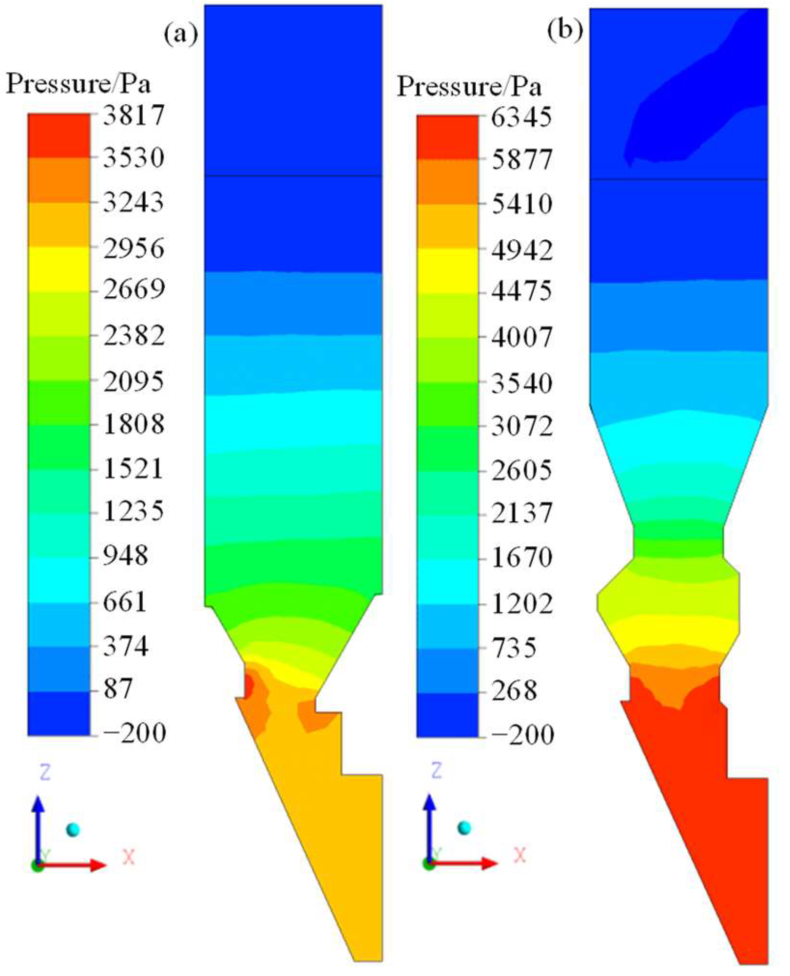
Figure 9 shows the pressure distribution cloud diagram of cooling gas in the existing furnace and Venturi furnace. For the existing furnace type, the pressure drop of the cooling gas was 4140 Pa, while for the Venturi furnace type, it was 6410 Pa, with an increase of 54.83%. This was explained by the fact that first, the stacking shape of the sinter bed was changed after the Venturi furnace type was adopted. The existence of the variable-diameter section changed the height/diameter ratio of the furnace type, which was equivalent to extending the height of the sinter bed. Second, the overall cooling gas velocity in the Venturi furnace type increased. According to the Ergun formula, the greater the gas velocity through the packed bed, the greater the resistance loss. The above factors led to a significant increase in the gas pressure drop. At present, the “short-circuit” phenomenon of cooling gas in the burden of a vertical cooling furnace in Meishan Steel is serious, resulting in a small pressure drop in the furnace and a low utilization rate of cold air. Increasing the air volume cannot improve the cooling effect of sinter, but it will seriously reduce the exhaust temperature. Therefore, the increase in the cooling gas pressure drop caused by the Venturi furnace type was acceptable. Moreover, the increase in the pressure drop meant that the power of cooling gas entering the burden was increased, which enabled it to penetrate more sinter layers with poor permeability to achieve a uniform distribution of gas velocity in the variable-diameter section. This not only inhibited the development of high-speed gas channels but also improved the gas–solid heat transfer efficiency. Of course, the gas pressure drop should not be increased too much to avoid increasing the cost due to excessive fan power and affecting the smooth operation of the furnace. Therefore, it was necessary to further design the structure of the Venturi furnace to take into account the improvement in the gas velocity distribution and the increase in the gas pressure drop.
5. Conclusions
To improve the serious problem of the “short circuit” of gas flow in the sinter vertical cooling furnace, a Venturi furnace type was proposed based on the structure of the vertical cooling furnace. The DEM–CFD model was used to study the influence of the Venturi furnace type on the burden distribution and gas flow. The conclusions were as follows:
- (1)
- The Venturi furnace type changed the direction of the high Dnv channel from vertical to inclined-vertical through wall tilt and reduced Dnv from >0.033 m to 0.028~0.03 m in the vertical part of the variable-diameter section, which shortened the length of the high Dnv channel and reduced its influence scope. At the same time, a new high Dnv channel would gradually form in the center area.
- (2)
- The improvement in voidage in the Venturi furnace type was mainly concentrated in the variable-diameter section. Compared with the existing furnace type, the Venturi furnace type could increase the minimum and average value of voidage from 0.28 and 0.315 to 0.31 and 0.33, respectively, making the voidage fluctuate twice along the longitudinal direction, thus changing the original U-shaped distribution into a W-shaped distribution. At the same time, the longitudinal fluctuation range of the voidage could be reduced from 0.28~0.39 to 0.298~0.37, and thus, the voidage in the middle area could always be maintained at a high level, which was conducive to more cooling gas entering the middle area and reducing the influence of high-voidage channels in the sidewall and center area.
- (3)
- After the Venturi furnace type was adopted, the cooling gas flow direction in the rectangular furnace cavity changed from vertical to vertical-inclined-upward, which was beneficial for increasing the gas–solid contact. In terms of the gas velocity, the cooling gas velocity significantly increased. In the vertical section, the average gas velocity was 2.34 m/s, which was 30.73% higher than the velocity of 1.79 m/s of the existing furnace type. In the variable-diameter section, the average gas velocity was 3.52 m/s, which was 72.55% higher than the velocity of 2.04 m/s of the existing furnace type. In terms of the airflow short circuit, the high-speed gas channel in the vertical section still existed, and another high-speed channel would be formed in the center area. However, the length of the two channels was reduced from 3.11 m of the existing furnace type to 2.52 m, thereby reducing the scope of its influence area. In the variable-diameter section, the high-speed gas channel disappeared, and the cooling gas velocity was evenly distributed transversely, which was conducive to weakening the airflow “short circuit”.
- (4)
- For the Venturi furnace type, the total gas pressure drop reached 6410 Pa, which was 54.83% higher than the pressure drop of 4140 Pa for the existing furnace type. Therefore, in the design of the Venturi furnace type, both the improvement in the gas velocity distribution and the increase in the pressure drop should be controlled within a reasonable range.
- (5)
- This study provides new improvement measures for improving the burden segregation and gas flow in a vertical cooling furnace, which can provide theoretical guidance for the structure optimization of the vertical cooling furnace in Meishan Steel. At the same time, it can also provide a reference for the optimization of the vertical gas–solid heat-exchange furnace for granular materials with a wide particle size distribution and poor permeability.
Author Contributions
Conceptualization, H.L.; data curation, T.Q.; funding acquisition, H.L.; investigation, H.L.; methodology, T.Q.; project administration, H.L.; resources, H.L.; software, T.Q.; supervision, Y.Z.; writing—original draft preparation, T.Q.; writing—review and editing, H.L. All authors have read and agreed to the published version of the manuscript.
Funding
This research was funded by the National Key R&D Program of China (grant number [2022YFE0208100]) and the Fundamental Research Funds for the Central Universities (grant number [N2225022]), and the APC was funded by [2022YFE0208100].
Institutional Review Board Statement
Not applicable.
Informed Consent Statement
Not applicable.
Data Availability Statement
No new data were created or analyzed in this study. Data sharing is not applicable to this article.
Acknowledgments
The authors are thankful to the National Key R&D Program of China for supporting this study.
Conflicts of Interest
The authors declare no conflict of interest.
Nomenclature
| mi | mass of particle i, kg | ηn | normal resistance coefficient, N·s/m |
| vi | transitional velocity of particle i, m/s | Vij | relative velocity of particles i and j, m/s |
| t | time, s | Vn,ij | normal component of relative velocity between particle i and particle j, m/s |
| ki | number of particles in contact with particle i | e | coefficient of restitution |
| Fcn,ij | normal contact force between particle i and particle j, N | n | normal unit vector |
| Fdn,ij | normal damping force between particle i and particle j, N | Kt | tangential spring stiffness, N/m |
| Fct,ij | tangential contact force between particle i and particle j, N | δt | tangential overlap, m |
| Fdt,ij | tangential damping force between particle i and particle j, N | G* | equivalent shear modulus, Pa |
| Fpf,i | fluid force on particle i, N | G | shear modulus, Pa |
| Fpf | combined force of particles acting on the fluid, N | ηt | tangential resistance coefficient, N·s/m |
| g | gravitational acceleration, m/s2 | Vt,ij | tangential component of relative velocity between particle i and particle j, m/s |
| Ii | rotational inertia of particle i, kg·m2 | μr | coefficient of rolling friction |
| ωi | angular velocity of particle i, rad/s | μs | coefficient of sliding friction |
| Tij | tangential force torque between particle i and particle j, N·m | ε | voidage |
| Mij | rolling friction torque between particle i and particle j, N·m | ρf | fluid density, kg/m3 |
| Kn | normal spring stiffness, N/m | uf | fluid velocity, m/s |
| δn | normal overlap, m | p | fluid pressure, Pa |
| E* | equivalent Young’s modulus, Pa | μf | fluid viscosity, Pa·s |
| R* | equivalent particle radius, m | n | number of particles in a grid cell |
| Ei | Young’s modulus of particle i, Pa | nc | number of sampling points within a grid where particles are located |
| Ri | radius of particle i, m | N | number of sampling points |
| γi | Poisson’s ratio of particle i | V | volume of grid cell, m3 |
| xi | position vector of particle i | Vi | volume of particle i, m3 |
| di | diameter of particle i, m |
References
- Guo, Z.C.; Fu, Z.X. Current situation of energy consumption and measures taken for energy saving in the iron and steel industry in China. Energy 2010, 35, 4356–4360. [Google Scholar] [CrossRef]
- Zhang, X.H.; Chen, Z.; Zhang, J.Y.; Ding, P.X.; Zhou, J.M. Simulation and optimization of waste heat recovery in sinter cooling process. Appl. Therm. Eng. 2013, 54, 7–15. [Google Scholar] [CrossRef]
- Tian, F.Y.; Huang, L.F.; Fan, L.W.; Qian, H.L.; Yu, Z.T. Wall effects on the pressure drop in packed beds of irregularly shaped sintered ore particles. Powder Technol. 2016, 301, 1284–1293. [Google Scholar] [CrossRef]
- Sun, K.; Tseng, C.T.; Wong, D.S.H.; Shieh, S.S.; Jang, S.S.; Kang, J.L.; Hsieh, W.D. Model predictive control for improving waste heat recovery in coke dry quenching processes. Energy 2015, 80, 275–283. [Google Scholar] [CrossRef]
- Cai, J.J.; Dong, H. The Method and Device of Sintering Waste Heat Recovery and Utilization with Vertical Tank. China Patent 200910187381.8, 4 February 2010. (In Chinese). [Google Scholar]
- Fu, J.P.; Cai, J.J. Numerical investigation and optimisation of heat transfer performance in a vertical sinter cooling packed bed using Taguchi and ANOVA methods. Iron Steel Res. Int. 2020, 27, 898–912. [Google Scholar] [CrossRef]
- Feng, J.S.; Zhang, S.; Dong, H.; Pei, G. Frictional pressure drop characteristics of air flow through sinter bed layer in vertical tank. Powder Technol. 2019, 344, 177–182. [Google Scholar] [CrossRef]
- Tian, F.Y.; Huang, L.F.; Fan, L.W.; Qian, H.L.; Gu, J.X.; Yu, Z.T.; Hu, Y.C.; Ge, J.; Cen, K.F. Pressure drop in a packed bed with sintered ore particles as applied to sinter coolers with a novel vertically arranged design for waste heat recovery. J. Zhejiang Univ.-Sci. A 2016, 17, 89–99. [Google Scholar] [CrossRef]
- Feng, J.S.; Dong, H.; Dong, H.D. Modification of Ergun’s correlation in vertical tank for sinter waste heat recovery. Powder Technol. 2015, 280, 89–93. [Google Scholar] [CrossRef]
- Feng, J.S.; Dong, H.; Liu, J.Y.; Liang, K.; Gao, J.Y. Experimental study of gas flow characteristics in vertical tank for sinter waste heat recovery. Appl. Therm. Eng. 2015, 91, 73–79. [Google Scholar] [CrossRef]
- Zhang, S.; Zhao, L.; Feng, J.S.; Luo, X.F.; Dong, H. Thermal analysis of sinter vertical cooler based on waste heat recovery. Appl. Therm. Eng. 2019, 157, 113708. [Google Scholar] [CrossRef]
- Cui, Z.; Shao, W.; Chen, Z.Y.; Cheng, L. Mathematical model and numerical solutions for the coupled gas-solid heat transfer process in moving packed beds. Appl. Energy 2017, 206, 1297–1308. [Google Scholar] [CrossRef]
- Zheng, Y.; Dong, H.; Cai, J.J.; Feng, J.S.; Zhao, L.; Liu, J.Y.; Zhang, S. Experimental investigation of volumetric heat transfer coefficient in vertical moving-bed for sinter waste heat recovery. Appl. Therm. Eng. 2019, 151, 335–343. [Google Scholar] [CrossRef]
- Cheng, Z.D.; Wang, H.T.; Feng, J.S.; Xia, Y.F.; Dong, H. Energy and exergy efficiency analysis of fluid flow and heat transfer in sinter vertical cooler. Energies 2021, 14, 4522. [Google Scholar] [CrossRef]
- Pan, L.S.; Wei, X.L.; Peng, Y.; Ma, Y.J.; Li, B. Theoretical study on the cooling procedure for vertical flow sinters. Appl. Therm. Eng. 2017, 127, 592–601. [Google Scholar] [CrossRef]
- Xu, C.Y.; Liu, Z.C.; Wang, S.C.; Liu, W. Numerical Simulation and Optimization of Waste Heat Recovery in a Sinter Vertical Tank. Energies 2019, 12, 385. [Google Scholar] [CrossRef]
- Fu, J.P.; Cai, J.J. Study of Heat Transfer and the Hydrodynamic Performance of Gas–Solid Heat Transfer in a Vertical Sinter Cooling Bed Using the CFD-Taguchi-Grey Relational Analysis Method. Energies 2020, 13, 2225. [Google Scholar] [CrossRef]
- Wu, W.Y.; Liu, X.J.; Liang, X.; Xia, D.H. Operation characteristics of waste heat recovery from high-temperature particles under varying temperatures and flow rates. Int. J. Therm. Sci. 2022, 172, 107283. [Google Scholar] [CrossRef]
- Zhang, X.K.; Ji, X.; Sun, J.J.; Zhang, Y.J.; Zhang, Z.H.; Ge, W. Segregation behavior of sinter in vertically arranged cooler with high performance GPU simulation. Chin. J. Mech. 2019, 51, 64–73. (In Chinese) [Google Scholar]
- Sun, J.J.; Zhang, Y.J.; Ji, X. Segregation of sinter particles in sinter shaft cooler. Iron Steel 2020, 55, 16–22. (In Chinese) [Google Scholar]
- Qi, T.F.; Li, H.F.; Sun, J.J.; Zhang, Y.J. Simulation of gas–solid flow in sinter vertical cooling furnace. J. Iron Steel Res. Int. 2023. [Google Scholar] [CrossRef]
- Xu, W.X.; Cheng, S.S.; Niu, Q.; Hu, W.; Bang, J.W. Investigation on the uneven distribution of different types of ores in the hopper and stock surface during the charging process of blast furnace based on discrete element method. Metall. Res. Technol. 2019, 116, 314–321. [Google Scholar] [CrossRef]
- Chen, J.S.; Zuo, H.B.; Zhao, H.B.; Xue, Q.G.; Wang, J.S. Burden circumferential mass segregation at the blast furnace with parallel hoppers. Powder Technol. 2022, 409, 117845. [Google Scholar] [CrossRef]
- Zhang, T.F.; Gan, J.Q.; Yu, A.B.; Pinson, D.; Zhou, Z.Y. Size segregation of granular materials during Paul-Wurth hopper charging and discharging process. Powder Technol. 2021, 378, 497–509. [Google Scholar] [CrossRef]
- Liu, W.L.; Chen, G.X.; Liu, C.S.; Zheng, D.Q.; Ge, M.M. Experimental and numerical study of pressure drop characteristics of soybean grain under vertical pressure. Appl. Sci. 2022, 12, 6830. [Google Scholar] [CrossRef]
- Zhou, H.; Xu, K.; Tian, X.; Kou, M.Y.; Wu, S.L.; Shen, Y.B. Influence of burden profile on gas-solid distribution in COREX shaft furnace with center gas supply by CFD-DEM model. Powder Technol. 2021, 392, 672–679. [Google Scholar] [CrossRef]
- Qi, T.F.; Huang, J.; Sun, J.J.; Zhang, Y.J. Flow behavior of sinter in shaft cooler with DEM simulation. J. Iron Steel Res. 2022, 34, 239–247. (In Chinese) [Google Scholar]
Figure 1.
Existing furnace type and Venturi furnace type. (a) Model dimension. (b) Slot model. (c) Computational grid.
Figure 1.
Existing furnace type and Venturi furnace type. (a) Model dimension. (b) Slot model. (c) Computational grid.

Figure 2.
Influence of gas velocity on pressure drop.
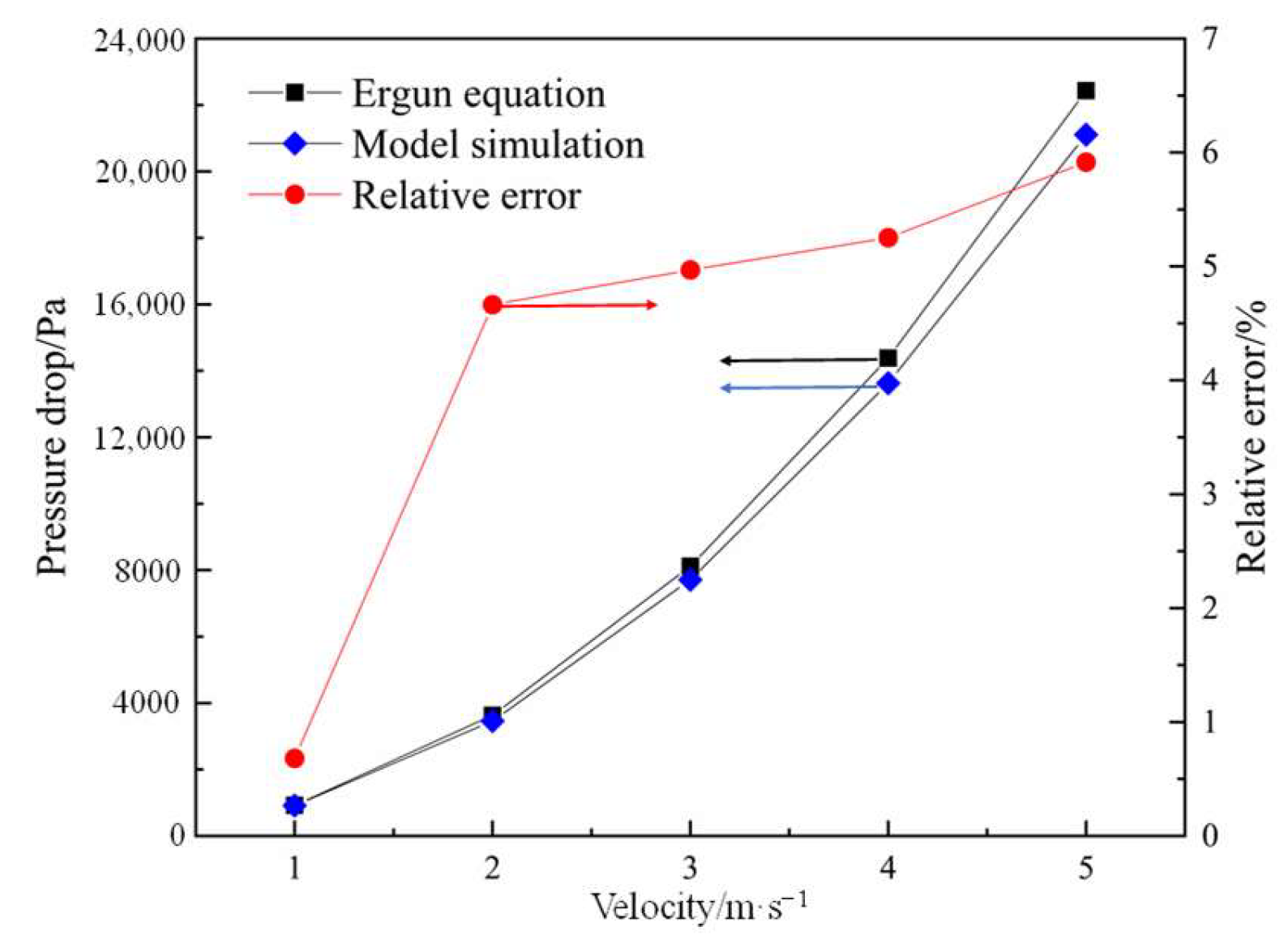
Figure 3.
Particle distribution during the discharging process. (a) Existing furnace type. (b) Venturi furnace type.
Figure 3.
Particle distribution during the discharging process. (a) Existing furnace type. (b) Venturi furnace type.
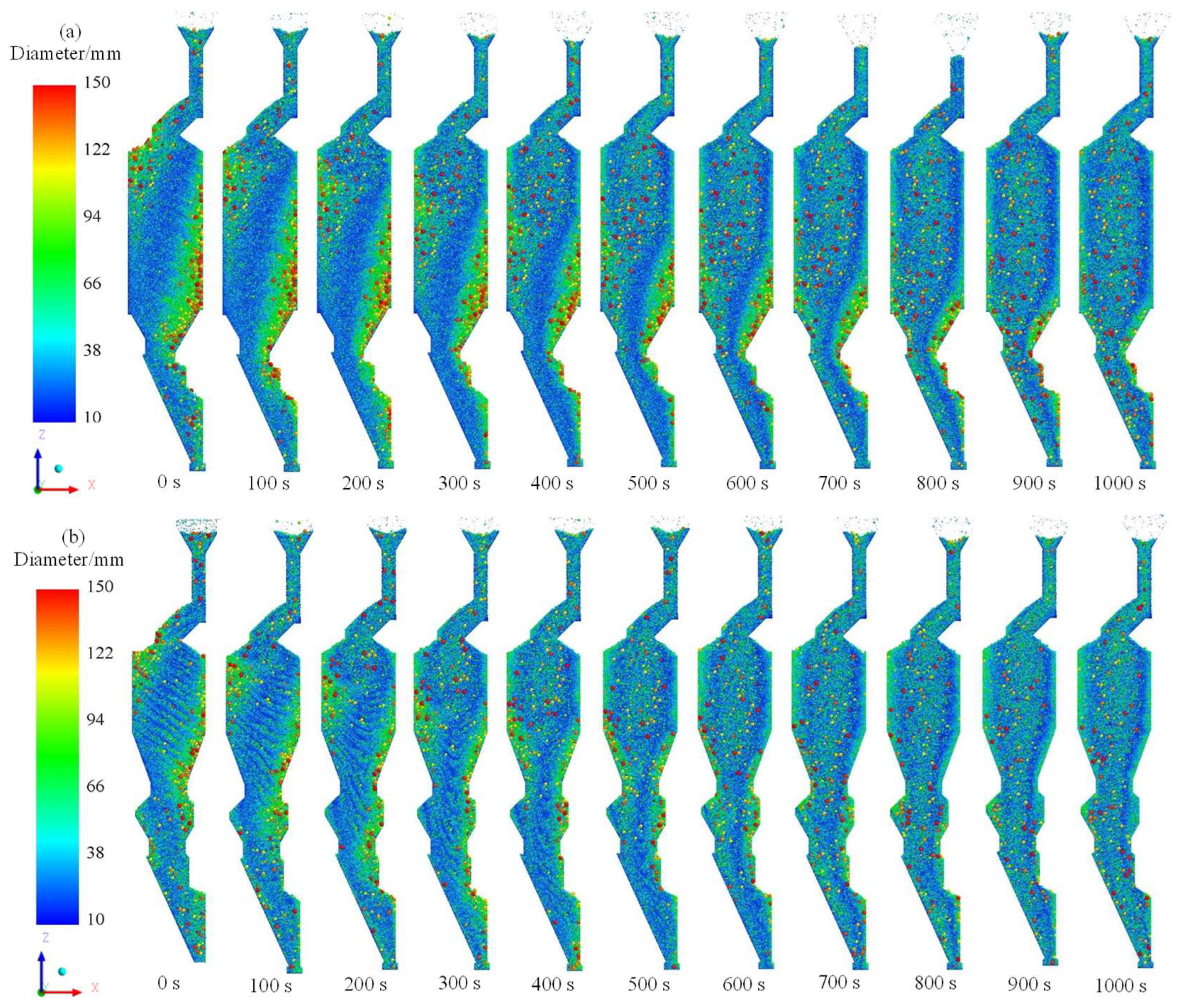
Figure 4.
Distribution of particle size and Dnv in the existing furnace type and Venturi furnace type. (a) Particle size distribution. (b) Dnv distribution.
Figure 4.
Distribution of particle size and Dnv in the existing furnace type and Venturi furnace type. (a) Particle size distribution. (b) Dnv distribution.

Figure 5.
Voidage distribution of sinter layer. (a) Voidage distribution map. (b) Voidage distribution at line V1.
Figure 5.
Voidage distribution of sinter layer. (a) Voidage distribution map. (b) Voidage distribution at line V1.
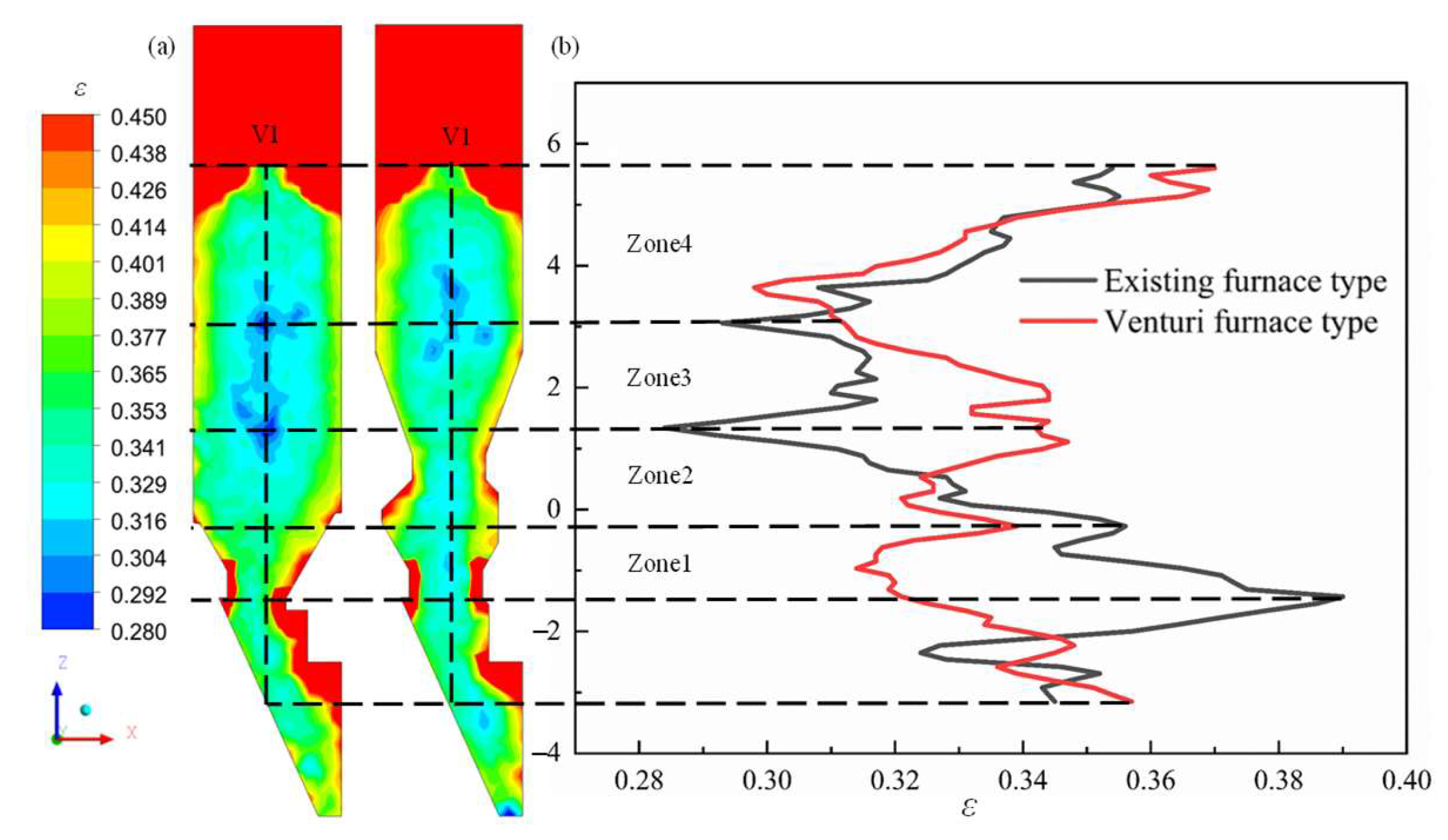
Figure 6.
Gas velocity vector distribution. (a) Existing furnace type. (b) Venturi furnace type.
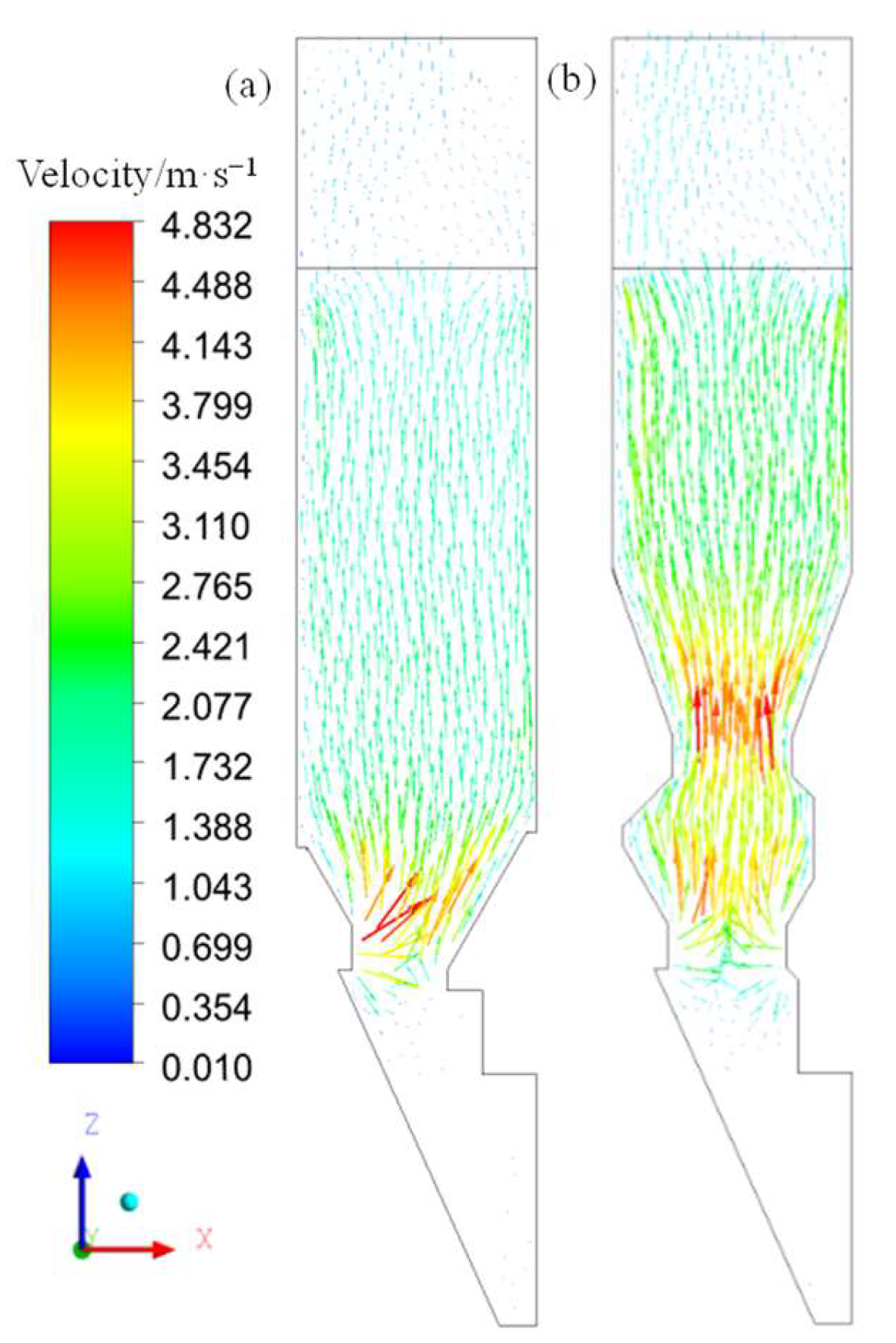
Figure 7.
Gas velocity distribution. (a) Existing furnace type. (b) Venturi furnace type.
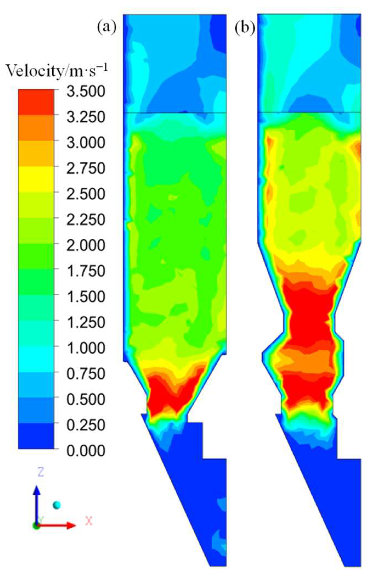
Figure 8.
High-speed gas channel distribution in different furnaces. (a) Existing furnace type. (b) Venturi furnace type and. (c) Venturi furnace type.
Figure 8.
High-speed gas channel distribution in different furnaces. (a) Existing furnace type. (b) Venturi furnace type and. (c) Venturi furnace type.
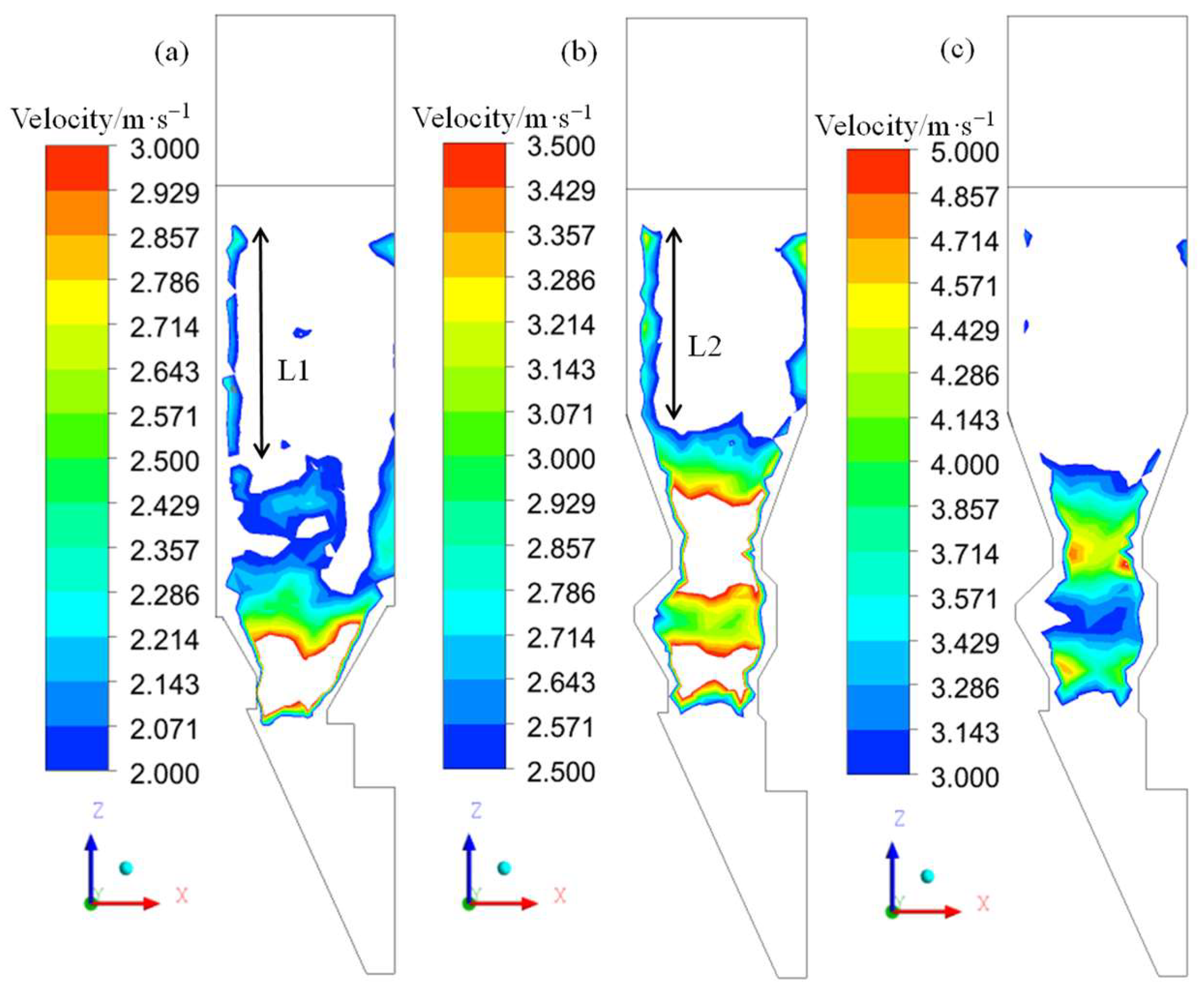
Figure 9.
Gas pressure distribution. (a) Existing furnace type. (b) Venturi furnace type.

Table 1.
Forces and torques acting on particle i.
| Symbol | Equation |
|---|---|
| Fcn,ij | |
| Fdn,ij | |
| Fct,ij | |
| Fdt,ij | |
| Tij | |
| Mij | |
| Fpf,i |
Table 2.
Sinter particle size distribution and mass fraction.
| Diameter, d/mm | 10~25 | 25~40 | 40~80 | 80~150 |
| Mass fraction | 20 | 35 | 30 | 15 |
Table 3.
Material properties and simulation parameters.
| Parameters | Sinter | Wall |
|---|---|---|
| Poisson’s ratio, γ | 0.25 | 0.3 |
| Density, ρs/(kg·m−3) | 2.6 × 10³ | 7.8 × 10³ |
| Shear modulus, G/Pa | 3.5 × 10⁷ | 7 × 10¹⁰ |
| Restitution coefficient, e | 0.25 | 0.2 |
| Static friction, μs | 0.38 | 0.45 |
| Rolling friction, μr | 0.08 | 0.16 |
| Gas density, ρf/(kg·m−3) | 1.225 | |
| Gas viscosity, μf/(kg/m·s) | 1.7894 × 10⁻⁵ | |
| DEM time step, s | 4 × 10⁻⁵ | |
| CFD time step, s | 4 × 10⁻⁴ | |
Disclaimer/Publisher’s Note: The statements, opinions and data contained in all publications are solely those of the individual author(s) and contributor(s) and not of MDPI and/or the editor(s). MDPI and/or the editor(s) disclaim responsibility for any injury to people or property resulting from any ideas, methods, instructions or products referred to in the content. |
© 2023 by the authors. Licensee MDPI, Basel, Switzerland. This article is an open access article distributed under the terms and conditions of the Creative Commons Attribution (CC BY) license (https://creativecommons.org/licenses/by/4.0/).
Share and Cite
MDPI and ACS Style
Li, H.; Qi, T.; Zhang, Y. Effect of Furnace Structure on Burden Distribution and Gas Flow in Sinter Vertical Cooling Furnace. Appl. Sci. 2023, 13, 11268. https://doi.org/10.3390/app132011268
AMA Style
Li H, Qi T, Zhang Y. Effect of Furnace Structure on Burden Distribution and Gas Flow in Sinter Vertical Cooling Furnace. Applied Sciences. 2023; 13(20):11268. https://doi.org/10.3390/app132011268
Chicago/Turabian StyleLi, Haifeng, Tengfei Qi, and Yongjie Zhang. 2023. "Effect of Furnace Structure on Burden Distribution and Gas Flow in Sinter Vertical Cooling Furnace" Applied Sciences 13, no. 20: 11268. https://doi.org/10.3390/app132011268
Note that from the first issue of 2016, this journal uses article numbers instead of page numbers. See further details here.