Article

Calibration of Micro-Parameters of a Mortar Cylinder Specimen under Simple Compression Using a 2D Discrete Element Model

by
Miguel Ortiz-Cahun
1,
Luis Fernandez-Baqueiro
2 and
Zenon Medina-Cetina
1,*
1
Zachry Department of Civil & Environmental Engineering, Texas A&M University, College Station, TX 77843-3136, USA
2
Facultad de Ingenieria, Universidad Autónoma de Yucatán, 97000 Merida, Mexico
*
Author to whom correspondence should be addressed.
Appl. Sci. 2023, 13(19), 10952; https://doi.org/10.3390/app131910952
Submission received: 1 March 2023 / Revised: 10 May 2023 / Accepted: 11 May 2023 / Published: 4 October 2023

Abstract

:
Masonry systems have been used extensively in historical, commercial, and residential buildings. A large number of experimental and computational studies have been conducted to investigate the behavior of masonry components and systems, including mortar, units (e.g., blocks), and walls. The Discrete Element Method (DEM) has been used to analyze masonry systems with a macro modeling methodology (i.e., structural systems like walls). Masonry systems and their components have not been analyzed using a micro-modeling methodology with the DEM. The objective of this paper is the deterministic calibration of micro-parameters of the mortar cylinder model based on a computationally efficient DEM model. To achieve this objective, a parametric analysis is introduced through a series of models of a mortar specimen tested under simple compression to explore the impact of the model micro-parameters when trying to reproduce a set of experimental observations conducted at the Universidad Autonoma de Yucatan Mexico (UADY). A calibration process based on optimization is implemented to determine the best estimates of the model’s micro-parameters. This paper is divided into three analyses. First, the particle size distribution of the mortar’s aggregate is used as a reference (i.e., scale 1), and then up-scaled 1.5 and two times using four particle sizes; second, using the two-times scaled particle size, the influence of varying particle sizes within a reference particle size distribution was explored (from one particle size to 4 particle sizes following the aggregate particle size distribution); and third, a parametric analysis is performed varying seven micro-parameters, one at the time, varying from 0.25 to 1.5, at 0.25 scale increments, on a model including four particle sizes. The results show micro-parameters and stress-strain curves of mortar for the different analyses, and a representation of the cross sections of the models, indicating the distributions of contact forces. All proposed models showed good agreement with the experimental observations (i.e., stress-strain curve). Also, it was observed from the proposed analyses that some micro-parameters vary as the particle size and the scaled particle size distributions change when using the same experimental stress-strain curve. Also, it was found that the proposed DEM must contain at least two particle sizes to significantly improve the particle interlocking to ensure that the mechanistic behavior reproduces the same experimental observations. Finally, from the results presented in this work, it is concluded that it is possible to produce a computationally efficient model that can later serve as a reference for future research accounting for other control variables such as particle shape, particle size distributions, the exploration of damage propagation effects, and most importantly their corresponding uncertainty quantification and propagation effects in masonry systems.

1. Introduction

Masonry systems have been used extensively in historical, commercial and residential buildings, and it is known that they can be vulnerable to extraordinary loading conditions such as wind or earthquakes [1,2]. Given the importance of these systems, a large number of studies have been conducted to investigate the behavior of masonry systems, including the masonry components: mortar, concrete blocks, and concrete frames [3,4,5,6]. These studies have been carried out by creating mesoscale models that correspond to mortar, block and block-mortar bonds [7], or macro-scale models that correspond to walls and masonry structures [1]. Those models are experimentally tested and then computationally analyzed.
There are several numerical models that can be used to successfully predict masonry behavior. Asteris and Plevris [8] categorized numerical modeling into two types: macro-modeling and micro-modeling. Macro-modeling generally refers to a one-phase material where the masonry system is idealized as a homogenous continuum. The use of the Finite Element Method (FEM) is thought of as a macro-modeling approach that permits the idealization of the masonry wall as a homogenized continuum model and, thus, accounts for the effect of mortar joints implicitly. On the other hand, micro-modeling allows us to explicitly represent the masonry components individually and consequently allows us to explicitly examine the mortar-block interface. The Discrete Element Method (DEM) can be used for micro-modeling.
The DEM was introduced by Cundall and Strack [9], and it is widely used in fracture mechanics and geomaterials interaction modeling to solve problems from mining, manufacturing and civil engineering applications. The DEM is a particle-based modeling method that allows for a complete particle detachment and large deformation of the specimens. The use of the DEM is particularly suitable for simulating shearing failure mechanisms in masonry structures. This method allows finite displacements and rotations of discrete particles (including complete detachment) and recognizes new contacts automatically as the calculation progresses. The use of the DEM is particularly suitable for simulating shearing failure mechanisms in masonry structures [10,11]. The discrete macro-elements approach has been used to model masonry elements and structures, in which each element could be a masonry unit or a group of masonry units [12,13].
There are different constitutive contact models that can be used in the DEM, such as parallel bonding, hertz, burger, and flat joint. Potyondy and Cundall [14] introduced parallel bonding as a constitutive contact model capable of reproducing cemented material behavior using a La du Bonnet granite DEM model. They conducted parameter calibration manually in order to match the experimental macro-properties of the specimen. Similarly, Potyondy [15] introduced the flat joint model as a constitutive contact model. The benefit of this contact model is that it allows for the matching of the ultimate capacity and tensile strength ratio ( q u / σ t ), which the parallel bond model is not capable of reproducing. On an Unconfined Compressive Strength test (UCS) with tensile strength chosen to match maximum tensile strength ( σ t ), the failure at peak load is triggered by disk rolling arising from a lack of moment resistance after bond failure. On the other hand, when using a flat-joint contact model, the tensile strength is chosen to match the σ t and shows resistance to partial damage. The ability to resist partial damage in the contact is suitable to model strain hardening that is observed in the stress-strain curve. In both contact models, the ultimate load ( q u ) is controlled by its shear strength. Therefore, it is relevant to investigate the behavior of the model’s micro-parameters for the constitutive contact model to better understand the mechanisms associated with reproducing the material experimental behavior.
The calibration of micro-parameters of numerical models is a key process for the generation of accurate predictions. Recent efforts have been developed to clarify a methodology for the assignment of micro-parameters to cemented/rock materials [16,17,18,19,20]. Nonetheless, micro-parameters are not the only factor influencing the DEM’s mechanical behavior. Potyondy and Cundall [14] demonstrated that the DEM’s Young’s Modulus has a clear dependence on the particle size (PS) of the a La du granite PFC3D model. Joshi [21] concluded that PS influences the sample’s ultimate stress and peak strain at a particular model PS-model size ratio. Ding et al. [22] concluded that the UCS and Young’s Modulus decrease with a wider Gaussian normal PS distribution (Dmax–Dmin), where D is the particle diameter. The aggregate shape considered in the model affects the model results; however, a simplified approach considering circular and spherical particle shapes in 2D and 3D DEMs, respectively, can lead to results in good agreement with the experimental observations [23,24].
The uniform and the Gaussian normal distribution are the more commonly used PSD models (PSD) in the DEM [22]. However, studies with non-uniform PSD have concluded that particle shape, sample packing, and PS affect the compressive strength, tensile strength, and strain localization of DEMs [25,26]. Furthermore, computational time represents a limitation in DEM simulations when attempting to reproduce the experimental PSD of the specimen, forcing researchers to up-scale or simplify the sample’s geometry. This practice can lead to the DEM’s inaccurate behavior [27].
Masonry components have been widely studied. Their physical and mechanical properties have been even characterized over time. Cement, sand, and lime are the main constituents of mortar. C270-19a ASTM [28] recognizes four different types of cement-lime mortars. Each one contains different proportions of cement, sand and lime, which results in different compressive strength, permeability and workability. Mortar is chosen to be investigated in this paper since it is one of the two main components of masonry systems.
C109/C109M-20 ASTM [29] presents the testing methodology for compressive strength testing of hydraulic cemented mortars. The standard suggests 2 in (5 cm) cube specimens. Nonetheless, Fernandez Baqueiro et al. [30] tested mortar cylinders of 15 cm diameter and 30 cm height under compressive strength. The purpose of this methodology was to produce a much finer stress-strain curve response of the material.
Studies related to mortar have been found in the literature where they use DEMs to characterize its mechanical properties [31,32,33]. Nonetheless, limited research is available on the influence of micro-parameters and PSD on the masonry components using DEM modeling. Moreover, the study of masonry as a system and its components using a micro-modeling methodology has not been further investigated [34].
In this research study, a mortar cylinder is modeled using a 2D-DEM utilizing PFC-2D software V.5.0 [35]. Models of a mortar cylinder under compressive strength test were developed. A calibration procedure throughout an optimization process was applied to determine the micro-parameters of the DEM. The models were calibrated using previous experimental tests conducted at the Autonomous University of Yucatan (Mexico) [24]. The contact model considered for the DEM is flat-joint.
This research study is divided into three analyses. Three PS and one PSD are considered in the first analysis. This is set to identify the influence of the PS on the mechanical behavior of the model and the variations of the micro-parameter’s values. One PS and four PSDs are considered in the second analysis. This is set to identify the influence of the PSD on the mechanical behavior and the variations of the micro-parameter’s values. In both analyses, estimates of the micro-parameters are obtained by fitting the model stress-strain curve with experimental observations. Finally, the third analysis consists of a parametric analysis, where seven micro-parameters are varied through increasing scale factors applied to a PSD, including four PSs. This analysis is set to identify the micro-parameters’ influence on the stress-strain curve of different DEM configurations.

2. Materials and Methods

The discrete element method can be described as a particle-based modeling approach, which uses disks or spheres to discretize a material ‘element.’ It uses Newton’s laws and the kinematics calculation to compute forces and update the particle position in the simulation. This method was first introduced by Cundall and Strack [9], and it is widely used in fracture mechanics and geomaterials modeling. This method allows finite displacements and rotations of discrete bodies (including complete detachment) and recognizes new contacts automatically as the calculation progresses. The contact forces of an assembly of particles are calculated by tracking the movement of individual particles [35]. The 2D-DEM, in particular, allows for the particles to have 3 degrees of freedom, which make them move translationally forward and backward on the x-axis (ux) and y-axis (uy) and rotate on the z-axis (φz).

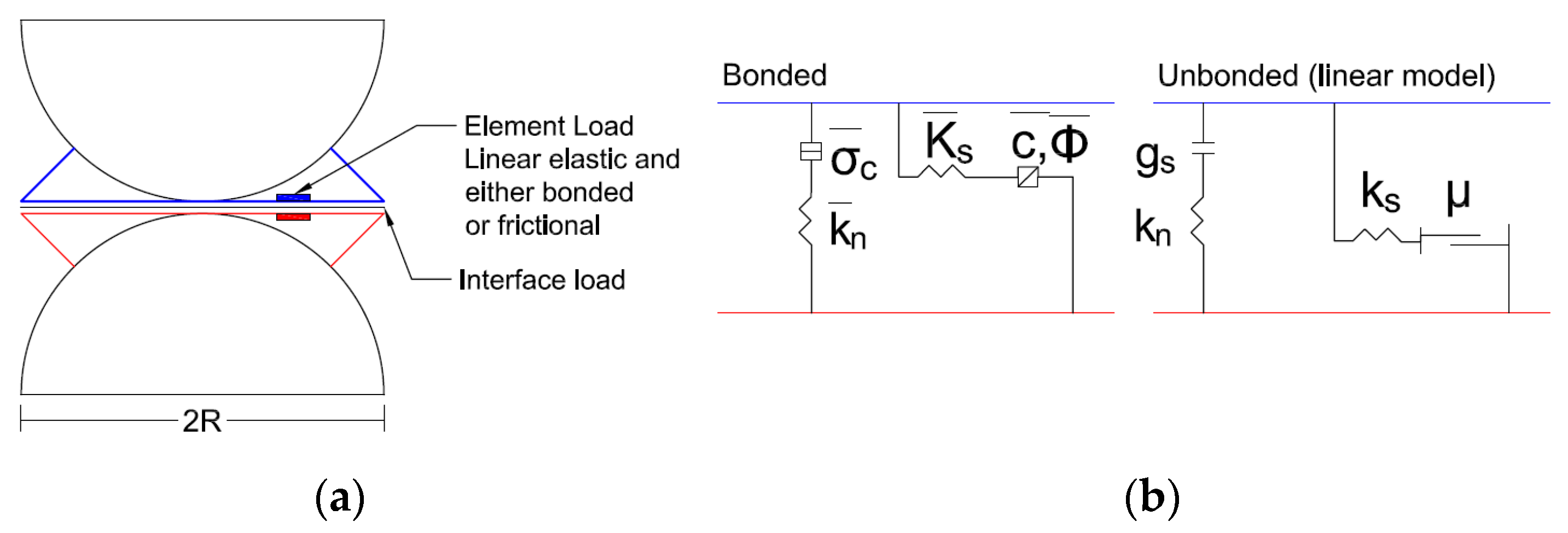
2.1. Particle Contact

The DEM introduces two types of contact between particles: the ball-ball contact and the ball-facet (wall) contact. In ball-to-ball contact, the total contact force is decomposed into shear and normal force. The normal force acts along the direction of the unit normal vector. The shear force operates on the contact plane along the perpendicular direction to the normal vector. The relative normal ( Δ U i n ) and tangential ( Δ U i s ) displacements are computed at every cycle (time-step). The normal ( F i n ) and shear ( F i s ) forces are calculated incrementally at every time-step (i) via the force-displacement law (Equations (1) and (2), respectively). In Equations (1) and (2), the normal ( k n ) and shear ( k s ) stiffnesses are constant material properties. The normal and shear forces are set to zero once the particle assembly is created and reaches equilibrium with respect to each other.
F i n = F i 1 n + k n Δ U i n
F i s = F i 1 s + k s Δ U i s

2.2. Flat Joint Model

DEMs are controlled at the particle contact level. Particle contact constitutive models are implemented to represent a material macro-behavior under different scenarios. PFC 2D/3D [35] has a variety of built-in contact models, such as the Parallel Bond, Hertz, and Flat Joint (FJ) models. The FJ model was introduced by Potyondy [15] and simulates the mechanical behavior of circular or spherical particles that might be bonded together at their contact points. In this paper, the FJ contact model is used because it is capable of reproducing the mechanical behavior of cemented materials [20].
Figure 1a presents the FJ contact model for particle-particle contact behavior and the representation of the contact interface. The contact interface is the plane formed by 2 particles in contact with a length equal to 2-times the radius (R) of the smallest particle. The contact interface is split into N equal-length elements (e). Each element can sustain tensile ( σ c ) and shear ( τ ) stresses, calculated using Equation (3). The tensile ( σ c ¯ ) and shear ( τ ¯ ) strengths limits are set at the beginning of the simulation. The σ c is calculated through the summation of normal forces ( F e n ) in the contact element and the area of the contact element ( A e ), which is a function of R (Figure 1a). The shear stress ( τ ) is calculated through the summation of tangential forces ( F e s ). The bonded state transitions to an unbonded state when either the σ c ¯ or τ ¯ strength limits are exceeded. The contact interface evolves from a fully bonded state to a fully unbounded (frictional) state (Figure 1b).
σ c = F e n A e ,   τ = F e s A e , A e = 2 R N
The bonded element state can sustain tensile and shear stress. The element breaks in tension if σ c is greater than the tensile strength ( σ ¯ c ) , Equation (4). The element breaks in shear if τ is greater than to shear strength ( τ ¯ ) that is calculated with a Coulomb criterion, Equation (5), and is a function of cohesive strength ( c ¯ ), tensile strength ( σ ¯ c ) and friction angle ( ϕ ¯ ). These strength parameters are set at the beginning of the simulation.
σ c > σ ¯ c
τ > τ ¯ = c ¯ + σ ¯ c tan ϕ ¯
The unbonded element state is linearly elastic with a frictional slip. The tensile strength ( σ ) is zero, and the compressive strength ( σ ˜ ) is a function of the element distance gap g s and the normal stiffness of the unbonded element ( k n ) (Equation (6)). Therefore, the shear strength ( τ ˜ ) follows the Coulomb criterion under compressive stress and is 0 otherwise (Equation (7)). In this equation μ is the friction coefficient.
σ ˜ { 0 ,       g s 0 k n g s ,       g s < 0
τ ˜ { σ μ ,       σ < 0 0 ,       σ = 0

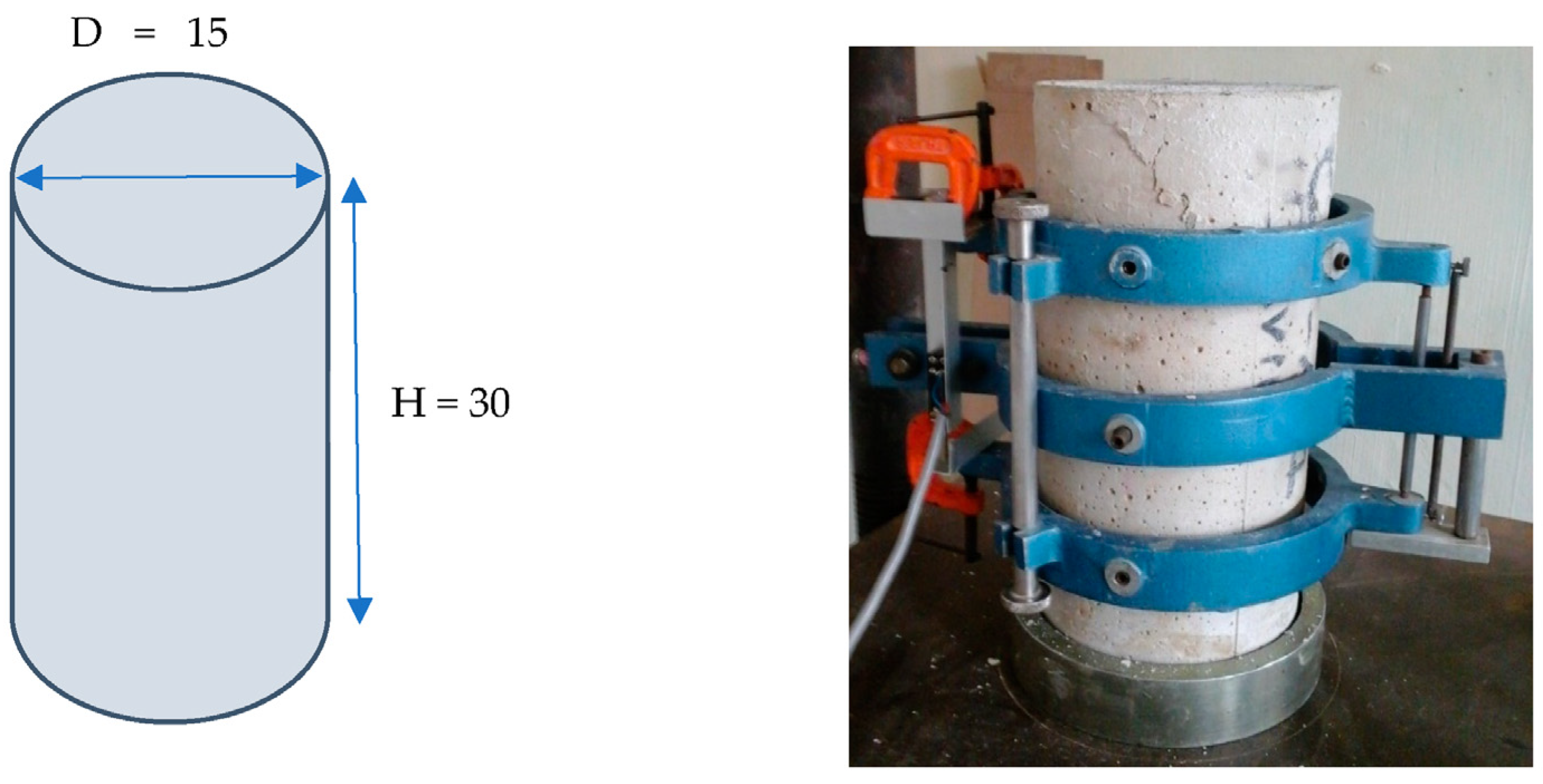
2.3. Mortar’s Specimen Description
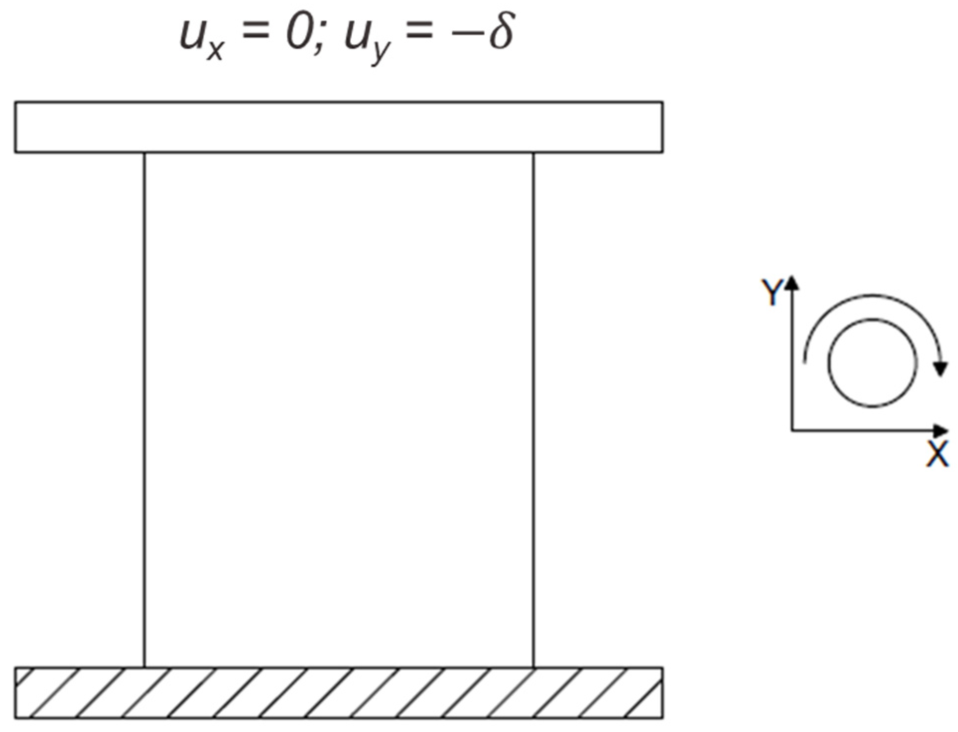
The mortar’s cylindrical specimen is shown in Figure 2. This has a 15 cm diameter and a 30 cm height. The experimental testing was carried out by Fernandez-Baqueiro et al. [30]. Details of the testing are described by Hernandez-Santillan [36]. The mortar was in proportion by volume in a ratio of 1:2:7 (Portland cement:lime:sand). The mortar’s sand PSD is presented in Figure 3.
Table 1 shows the mortar properties. These properties were obtained from the experimental observations of the reference specimen [24] and from the literature by matching a similar material composition (binder/aggregate) and compressive strength.

3. DEM Simulations

This work introduces a 2D DEM of a mortar specimen. The 2D DEM corresponds to the cross-section of a cylindrical mortar specimen. The width and height of the model cross-section correspond to the diameter and the height of the mortar cylinder. 2D DEMs of cylindrical specimens have been used to model triaxial tests in granular and brittle materials [43,44].
The solver software used in this work was the Particle Flow Code 2D (PFC2D 5.0) by Itasca Consulting Group [35]. The computational system processor was an Intel® Xeon® Gold 6248 CPU @2.50 GHz (four processors) and 768 GB RAM memory. Following the process from Potyondy and Cundall [14] and the PFC2D material generation process [35], the simulation process was divided into five stages.
Particle generation: A rectangular material vessel is created that contains the particles at half their final size and placed randomly within the vessel bounded with frictionless walls. The generated particles have a linear contact model (linear behavior) at this stage, and the properties are specified in Table 2. The friction coefficient was manually calibrated from the experimental value. The number of particles was calculated with respect to the overall porosity of the sample and the particle radius. Porosity was re-calculated from Equation (8). This equation is suggested by Wang et al. [45] as a correction for modeling in two dimensions in the DEM.
n 2 D = 0.42 × n l a b 2 + 0.25 × n l a b
where n 2 D is the initial 2D porosity and n l a b is the experimental porosity. The damping ratio is selected to ensure quasi-static conditions [14]. The particles are allowed to re-arrange under a low friction coefficient while the particles’ radius is increased to their final size. A low isotropic stress is applied by modifying the diameters of all particles simultaneously. Once static equilibrium was reached, the facets/walls were deleted.
Bond creation: flat joint material properties were assigned through the specimen between the particles that satisfy the installation gap (particles-particle separation less than or equal to 2 × 10 4 m). Bahaaddini, Sheikhpourkhani, and Mansouri [20] used a 0.4 installation gap ratio ( g ¯ /dmin) for their model. In this work, it was used a 0.24 installation gap ratio since it created adequate particle connectivity to reproduce the mortar’s behavior. The remaining particle-particle contacts and contacts formed during the simulation process were assigned the linear contact model with properties derived from the linear contact group of the flat jointed material properties [24]. The top and bottom facets were created after the forces and moments were set to 0 after the bond creation.
Boundary condition: first, the smoothing algorithm was implemented and consisted in setting the reference gap to the contact gap for all-particle with a ball-facet contact with a negative contact gap and then removing the overlap created between the particles and the facet, as shown in Figure 4.
After the smoothing operation is completed, there are no forces or moments in the specimen’s particle contacts. Figure 5 presents the DEM’s boundary conditions, where the vertical displacement (y-axis) is allowed at the top boundary/facet to apply the load. The bottom boundary/facet is fixed (ux = 0, uy = 0).
Seating: the seating phase consists of loading the specimen at maximum stress of 10% of the expected q u of the sample. This process creates ball-facet contacts since the smoothing phase only affects the particles overlapping the vessel. After the seating phase has been finalized, the system is brought back to static equilibrium with the facets fixed.
Uniaxial loading: the top facet is assigned with a constant downward velocity of 0.02 m/s. This velocity is selected since it ensures quasi-static modeling, and it is within the 0.016–0.2 m/s range used by other researchers [22,46].

4. Experimental Methodology

This study is divided into 3 analyses. Three particle scales (1.0, 1.5, and 2.0) and 1 particle size distribution (PSD) approximated by using 4 particle sizes were considered in the first experiment. Analysis 1 is set to identify the scale influence on the mechanical behavior of the model and the variations of the micro-parameters’ values. Incrementing the particle scale (up-scaling) has been successful in previous studies [45,47] and helps to reduce the computational cost of the DEMs. One particle scale (up-scale factor of 2.0) and four PSD are considered in the second experiment, represented by using a sequence of 1 to 4 PS. The second analysis is set to identify the PSD influence on the mechanical behavior and the variations of the micro-parameters’ values. In both analyses, the micro-parameters are obtained by fitting the model stress-strain curve with the reference experimental observations (axial stress vs. axial strain curve). The third analysis corresponds to a parametric study where seven micro-parameters are allowed to vary through 4 scale factors. The third analysis uses four PS and one up-scale factor of 2.0 and is set to identify the micro-parameters’ influence on the stress-strain curve of the mortar cylinder under compressive strength.

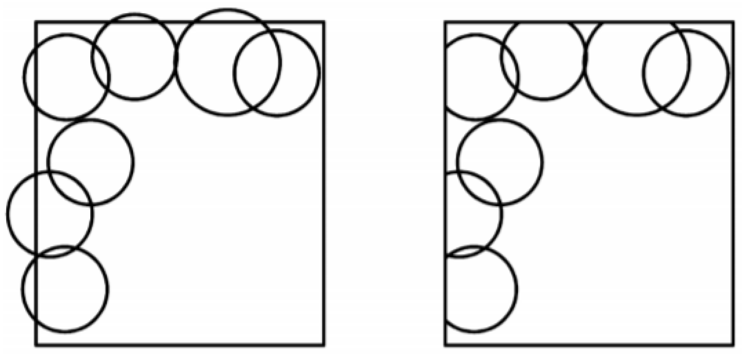
4.1. Particle Size Distribution: Analysis 1

Experiment one is set to identify the particle scale influence on the mechanical behavior of the model and the variations of the micro-parameters’ values. A PSD is selected consisting of 4 PS, D 80 , D 60 , D 40 , and D 20 , as shown in Figure 6. This PSD is called herein PSD4_S1. The up-scaling technique consists of incrementing the PSD by the selected factor. The DEMs with up-scaled factor (USF) of 1.5 and 2.0 are herein called PSD4_S1.5 and PSD4_S2, respectively. A USF of 1.0 corresponds to the experimental sand particle size distribution of mortar presented in Figure 3.
The PSD4 DEM’s micro-parameters are calibrated to reproduce the mortar’s reference experimental stress-strain curve. The calibration process is based on a non-linear least square optimization algorithm [48]. The mortar cylinder simulation process is presented in Figure 7. The first step is specimen generation, as presented in Section 3. The second step is assigning the contact model initial micro-parameters. The initial set of micro-parameters ( θ 0 ) values for the optimization procedure were obtained from the experimental observations and a manual calibration process (Table 3). The set of micro-parameters ( θ ) to be calibrated through the optimization procedure is θ = { E L C ,   E F J ,   σ ¯ c ,   c ¯ , ϕ ¯ ,   μ   } , where the remaining model parameters are assumed to be constant during the optimization process. The third step corresponds to the application of load increments to reproduce the compressive strength test. The fourth step is the calculation of the objective optimization function (ε) as ε = Σ ( f o b s f p r e d ) 2 , where f o b s is the stress-strain experimental data, and f p r e d is the stress-strain DEM results. The set of micro-parameters are modified until the optimization objective function is less or equal to 1%.

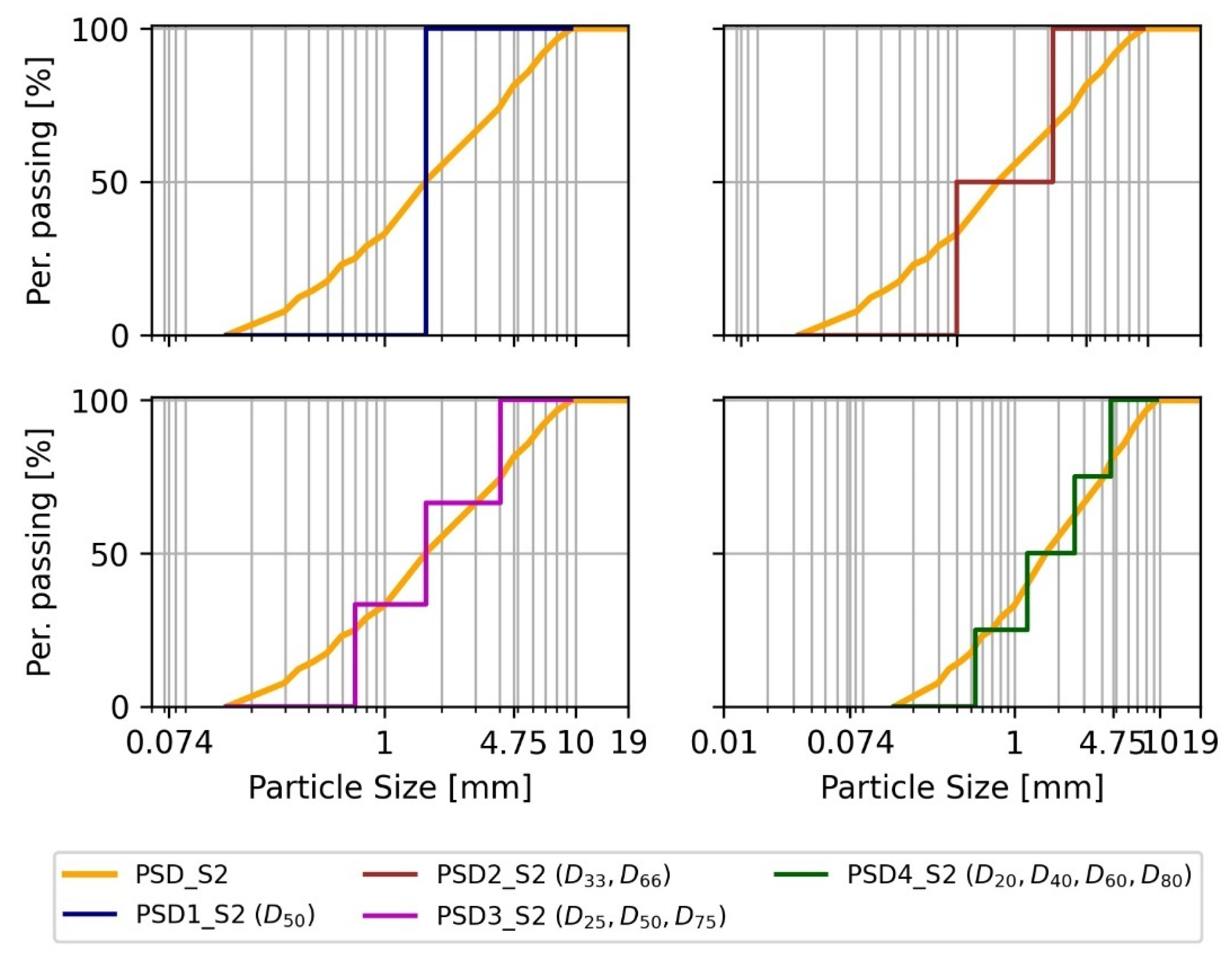
4.2. Particle Size Distribution Analysis: Analyses 2 and 3

Analysis 2 is set to identify the PSD influence on the mechanical behavior of the model and the variations of the micro-parameters’ values. For this analysis, a scale factor of 2.0 is selected to reduce the computational time. Four DEMs are formulated with different PSDs, as presented in Figure 8. PSD1_S2 contains 1 PS corresponding to D50. Similarly, PSD2_S2 and PSD3_S2 contain 2 and 3 particle sizes, respectively, and their corresponding particle sizes are D33 and D66, and D25, D50, and D75, respectively. PSD4_S2 is the same as defined in analysis one.
The DEM’s micro-parameters are calibrated to reproduce the mortar’s reference experimental stress-strain curve. The calibration process is a non-linear least square optimization algorithm [48]. The initial parameters’ values correspond to the calibration of the PSD4_S2 model micro-parameters ( θ PSD 4 _ S 2 ) obtained in analysis one. Then θ is calibrated through the optimization process as described for analysis one.

4.3. Parametric Analysis: Analysis 3

This analysis consists of the study of the micro-parameters’ influence on the stress-strain curve of the mortar cylinder under a compressive strength test. The PSD4_S2 DEM is selected, and its calibrated micro-parameters ( E L C ,   E F J ,   σ ¯ c ,   c ¯ , ϕ ¯ ,   μ ,   k r a t ,   and   k ¯ r a t ) from analysis 1. To perform the parametric analysis (analysis 3), each parameter is scaled individually into 4 factors: 0.25, 0.50, 1.25, and 1.50, with respect to the reference PSD of the mortar’s aggregate (scale factor 1.0). In this process, 1 micro-parameter is scaled at a time, and the other micro-parameters are maintained with their initial value.

5. Results and Discussion

5.1. Particle Size Analysis: Analysis One

Figure 9 shows the stress-strain curves of PSD4 DEMs with particle size scales 1.0, 1.5, and 2.0 and the micro-parameters obtained from the optimization procedure. It is observed that the stress-strain curve is well-fitted using the three scales considered in this work. The optimization objective function varies between 0.07 and 0.09.
There is a decrease in computational effort when the particle size is up-scaled. As represented in Figure 10, there is an increment in simulation time when there is an increment in the number of particles constituting the specimen (the larger the scale factor, the smaller number of particles).
Table 4 lists the calibrated micro-parameters for PSD4 DEMs with respect to their corresponding up-scale factor. All details about each parameterization are included in Table 4, where the DEM’s characteristics are presented, the specimen scale (scale), number of particles, number of particle contacts (CN), flat joint contact area (FJA), and the simulation time (ST). The flat joint contact area is defined as the summation of the area generated by the interface plane (Figure 1) of the contact of two particles. It is observed in this table that the micro-parameters μ and ϕ ¯ had a significant change when the particle size scale was increased, having an increment of 39% and 51% from scale 1 to 2, respectively. The remaining micro-parameters show minor variations across the differently-scaled DEM.
Figure 11 presents the variation of the friction coefficient ( μ ) and friction angle ( ϕ ¯ ) micro-parameters with respect to the flat joint area (FJA) for the three PSD DEMs described above. The FJA decreased as the number of particles was reduced and as the PS was up-scaled. The friction coefficient and the friction angle increment compensate for the reduction of particle interlocking, reduced by the increment of particle scale and the reduction of the number of particles, and hence the number of contacts within the sample.
Figure 12 shows a representation of the mortar’s specimen cross-section, illustrating the concentration of forces between particles for the three scaled PSD4 DEMs when the normal strain εyy is 0.001. Notice that the contact force’s concentrations are more localized when the particle scale factor equals one; as the PS scale is increased, the concentration of forces cover larger regions within the specimen. This is due to the particle contact interface being larger, as presented in Table 4 (FJA/CN/1000), which measures the FJA per every 1000 contacts. The particle contact interface is larger due to larger particles, and it has to withstand larger forces than the PSD4_S1 DEM since there are fewer particle contacts, and thus, there is less FJA to distribute the forces within the sample. Consequently, in order to be able to reproduce the stress-strain behavior as the experimental observations, the friction coefficient and the friction angle increase by 61% and 107%, respectively, when the FJA decreases by approximately 100%.

5.2. Particle Size Distribution Analysis: Analysis Two

Figure 13 shows the stress-strain curves of the PS DEMs compared with the experimental stress-strain curve. It is observed that by increasing the particle size distribution resolution (i.e., increasing the number of particle sizes from one to four), the DEM’s stress-strain shows a better fit with the experimental data. This effect is also validated from the optimization’s objective function residuals of 0.33, 0.24, 0.17, and 0.09, corresponding to specimens PSD1_S2, PSD2_S2, PSD3_S2, and PSD4_S2, respectively.
Also, a reduction in simulation time was observed when there was a reduction in the number of particles constituting the specimens (Figure 14). The reduction of particles was due to a reduction in the PSD resolution decrease.
The micro-parameter values obtained from the optimization process for each specimen are listed in Table 5. Additionally, Table 5 introduces two additional DEM characteristics: The Drat, which constitutes the ratio between the maximum and the minimum particle diameter (Dmax/Dmin), and the L/Drat ratio, where L is the largest dimension of the specimen, which in this case corresponds to the height (0.30 m). The L/Drat and Drat have been used previously [14,22] to measure the homogeneity of the particle diameter sizes conforming to a DEM. E L C and c ¯ show decreases of 40% and 67%, respectively, and ϕ ¯ and μ shows about a two-times increase when the PSD is also increased. The σ ¯ c and E F J micro-parameters do not show a significant variation.
Figure 15 includes plots showing the trends of the four DEMs’ micro-parameters obtained through the optimization process. The variation of the ϕ ¯ , c ¯ , and μ is analyzed considering different specimen characteristics. Particular trends for each parameter can be identified with respect to Drat. Lower values of Drat produce particle size homogenization, which effect generates lower particle interlocking, producing compensation from the ϕ ¯ , c ¯ , and μ micro-parameters values in order to reproduce the mortar’s reference experimental stress-strain curve. Additionally, Figure 16 shows a representation of the specimen’s cross-section showing the contact forces concentration for the four DEMs. From this figure, it is observed that the contact forces concentrations are significantly more localized. This is due to the FJA per 1000 contacts (FJA/CN/1000) increasing, denoting larger contact interfaces. Therefore, the stresses generated by the axial loading are distributed among a higher quantity of contacts when the PSD is increased. Hence, the effect of heterogeneity on the DEM impacts the micro-parameters values and the mechanical behavior of the DEMs. In addition, it is important to note that even though the uniform PSD model (PSD1_S2) was able to fit the stress-strain curve of the experimental observations, the micro-parameters values show a high variation compared with the PSD4_S2. This variation is due to the deficiency of particle interlocking created by the homogeneity of its particle size. Therefore, it is recommended that the DEM contains at least two particle sizes to ensure that the micro-parameters values and the mechanistic behavior represent the experimental observations.

5.3. Parametric Analysis—Analysis Three

In this analysis, a simulation is carried out, modifying one micro-parameter at a specific scale while the others are kept constant. The PSD4_S2 DEM is selected for the parametric analysis, and its calibrated micro-parameters ( E L C ,   E F J ,   σ ¯ c ,   c ¯ , ϕ ¯ ,   μ ,   k r a t ,   and   k ¯ r a t ) are taken from analysis one.
The effect of each micro-parameter is presented in Figure 17. The red arrows at every plot indicate the trend going from a smaller to a larger value for the given micro-parameter. The DEM’s Young’s Modulus (macro-property) increments as the ELC increments, and k r a t decreases. There is a slight increment of the DEM’s peak stress when increasing the EFJ and σ c ¯ . In particular, c ¯ ,   μ , and ϕ ¯ show a direct influence on the peak stress when incrementing their values. The σ c   ¯ , ϕ ¯ , and μ increase the hardening section when the micro-parameter value increases. On the other hand, the k ¯ r a t does not depict a clear trend when varying the initial micro-parameter value from a minor to a larger scale. It is concluded that the micro-parameters that have a greater effect on the compressive behavior of mortar are σ c   ¯ , c ¯ ,   μ ,   k r a t and ϕ ¯ . In order to model masonry under compression, it is necessary to simulate mortar and units under compression. This research contributes to this goal. Complementary experimental results, such as tensile splitting test, are required to better calibrate the other micro-parameter of mortar ( E F J , and k ¯ r a t ).

6. Conclusions

This research work focuses on the micro-parametric calibration of mortar based on a cylindrical specimen, which is modeled using the DEM, considering the effect of particle size scale and particle size distribution on the mechanistic behavior of the specimens. The numerical solver used for conducting the simulations was ITASCA’s PFC-2D, using three particle scales (1.0, 1.5, and 2.0) and from one to four particles to represent varying particle size distributions. Additionally, a parametric analysis is implemented with a variation of the micro-parameter at scale factors of 0.25, 0.50, 1.50, and 2.0.
The most relevant findings of this work are:
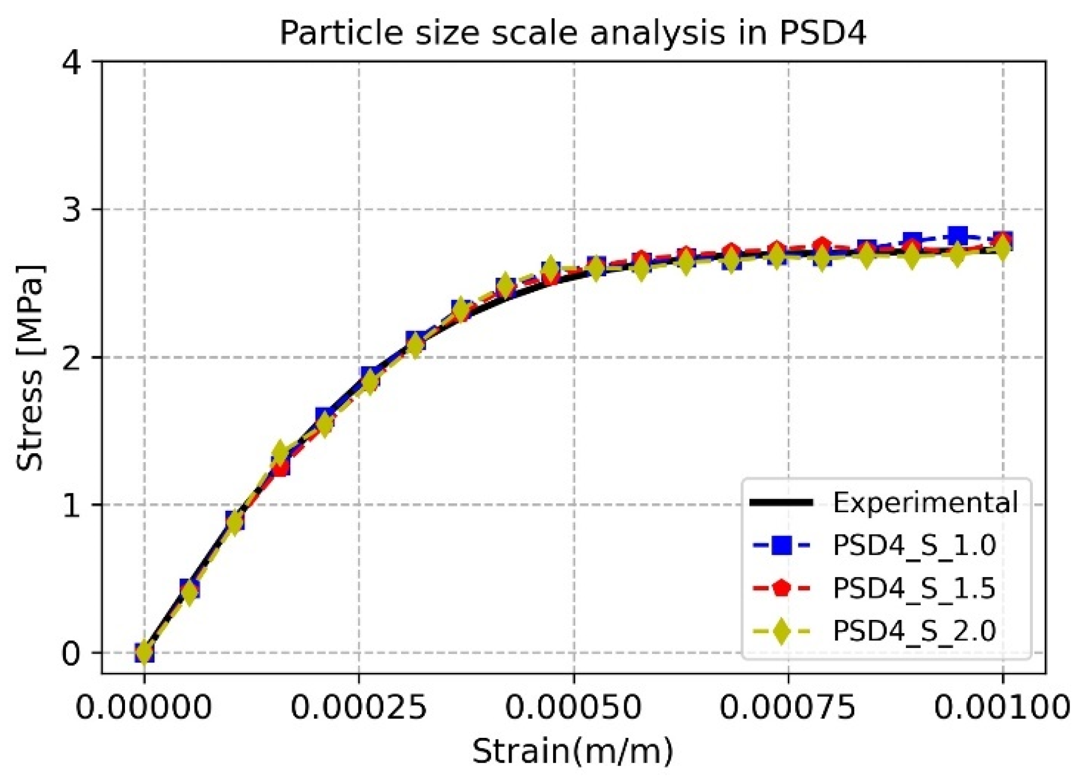
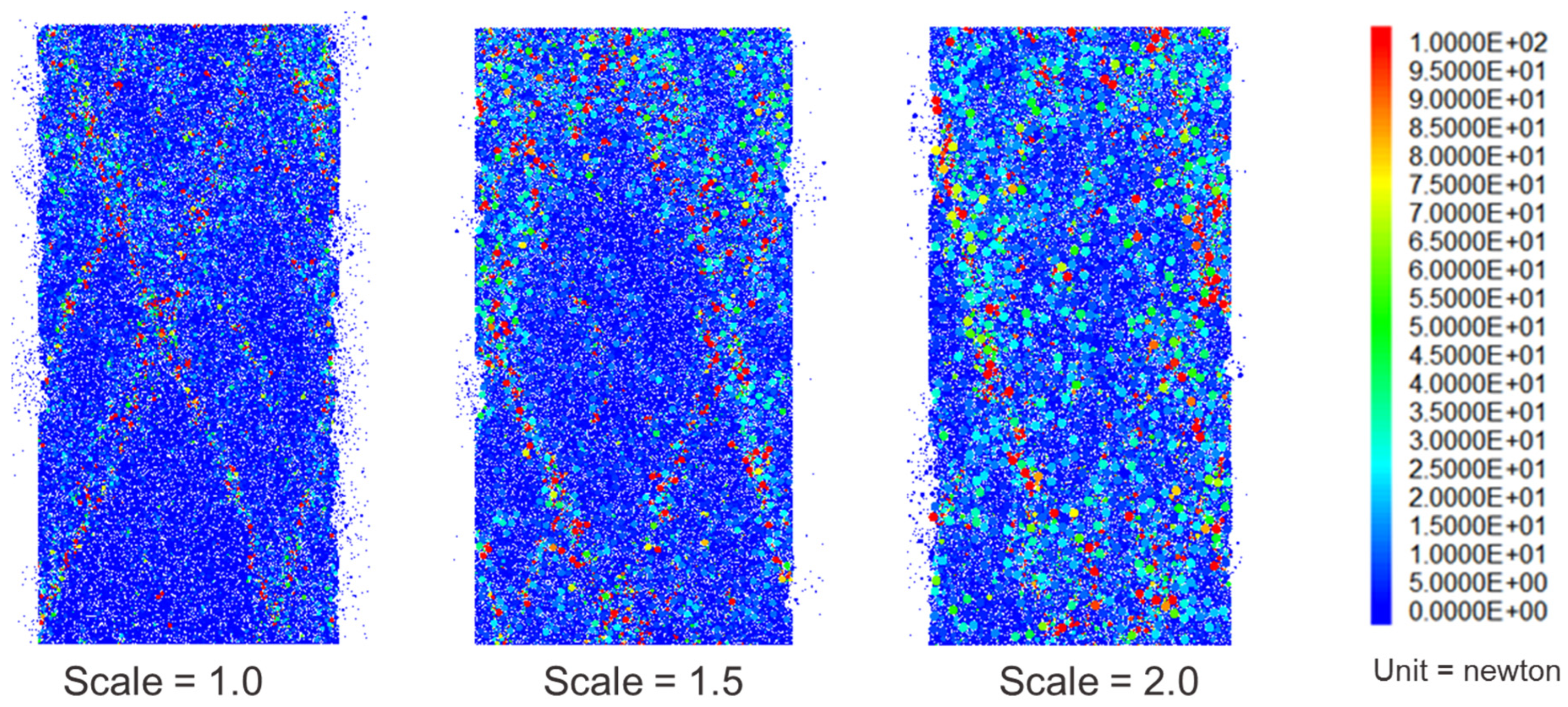
  • The DEM’s stress-strain curves are well-fitted with respect to the experimental data considering different particle size scales. Nonetheless, it is observed more localized concentrations of forces in the DEMs when the particle size scale is smaller;
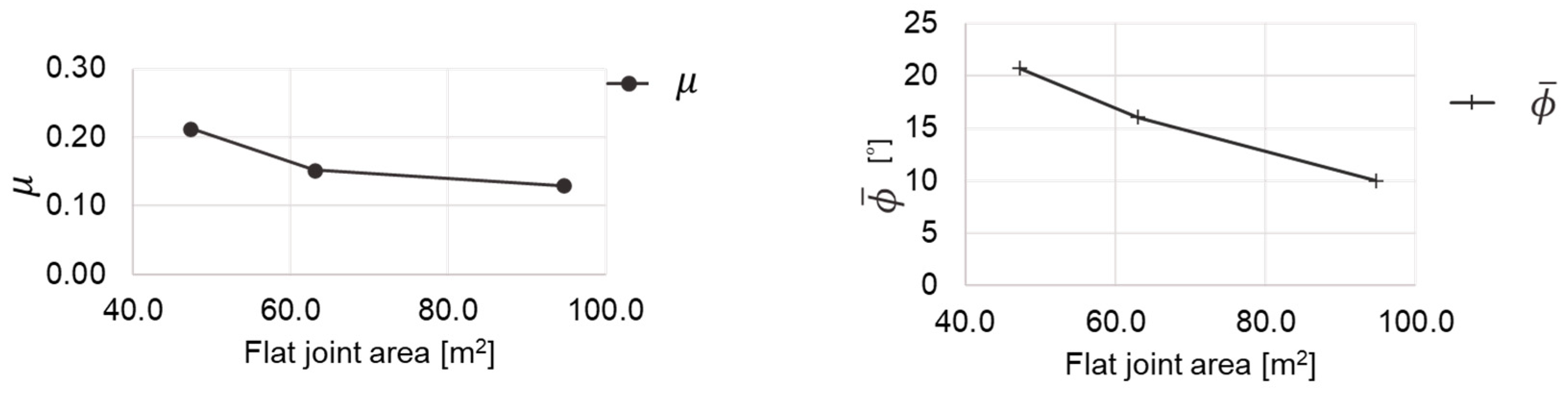
  • There is an increase in μ and ϕ micro-parameters when there is an increment in the particle size scale factor due to the reduction of particle contact area in the specimens;
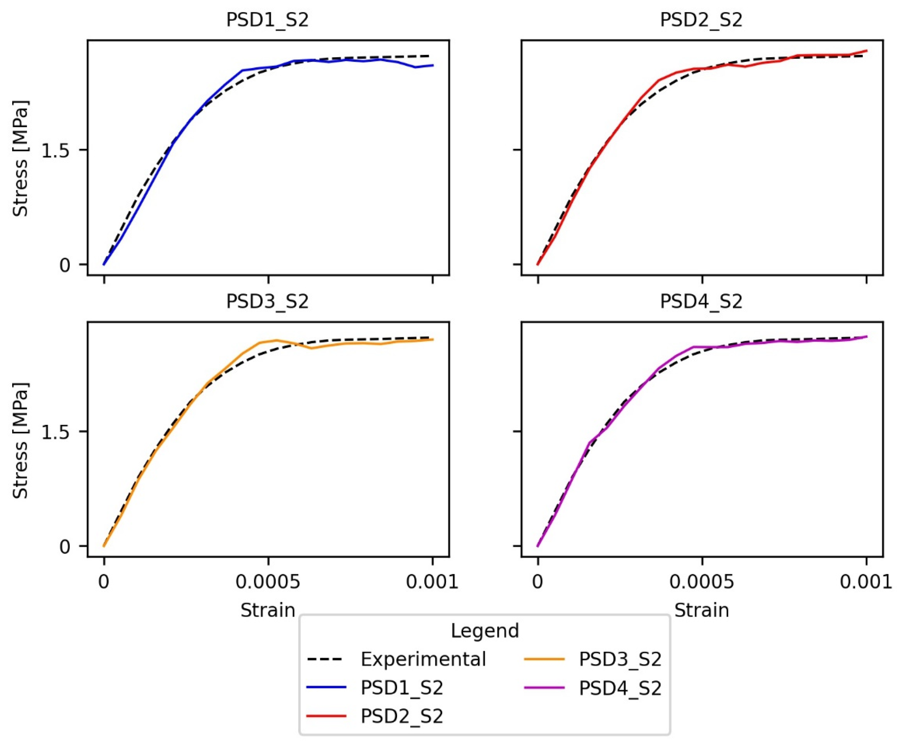
  • The DEM’s stress-strain curve shows a better agreement with the experimental data when increasing the particle size distribution resolution. It is observed more localized concentrations of forces in the DEMs when the particle size distribution resolution is higher;
  • The ϕ ¯ and μ micro-parameters increment and the c ¯ decrement when there is a decrement in the particle size distribution resolution. This is due to the decrease in the particle interlocking caused by the reduction of the particle size distribution resolution;
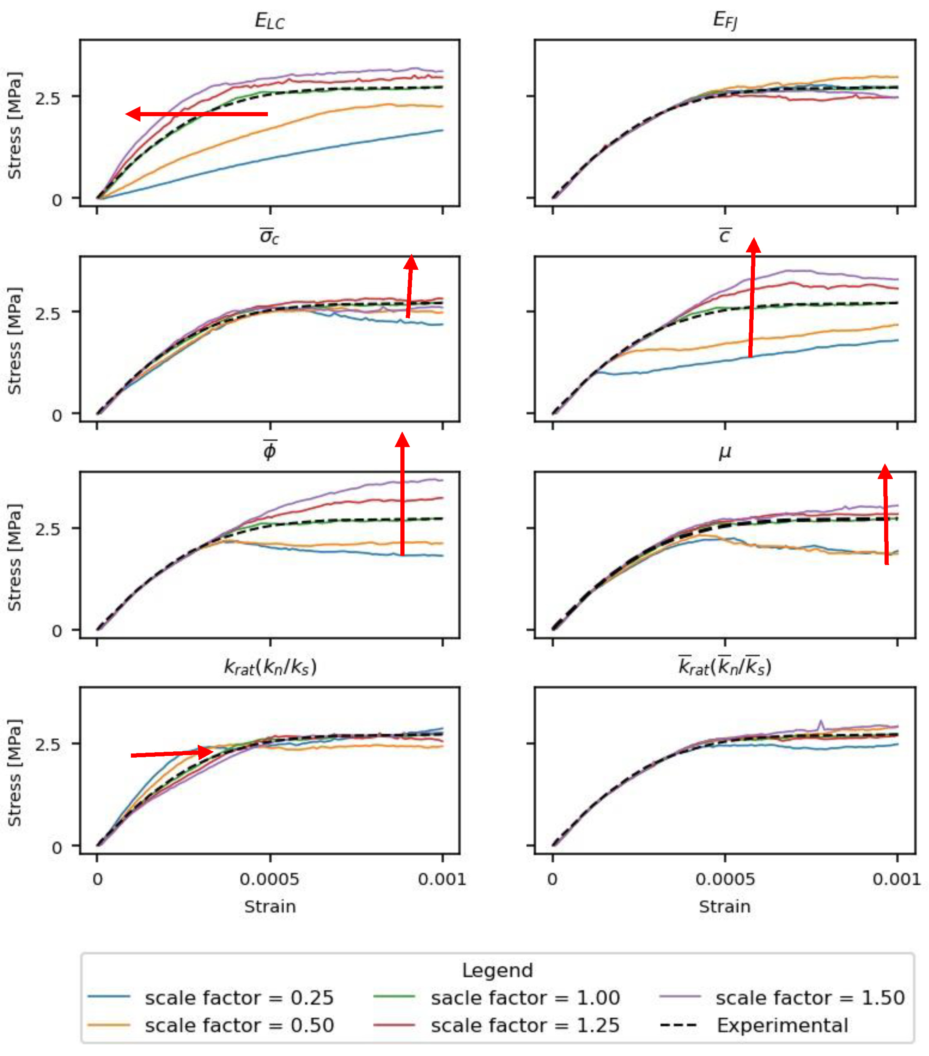
  • The ELC micro-parameter increments the macro-Young’s modulus of the DEM. The c ¯ ,   μ ,   ϕ micro-parameters increment the peak stress. Additionally, the σ c   ¯ , ϕ ¯ and μ micro-parameters increment the hardening section;
  • It is recommended that the DEM contains at least two particle sizes to improve the particle interlocking and ensure that the micro-parameters values and the mechanistic behavior represent the experimental observations.
Finally, from the results presented in this work, it is concluded that it is possible to produce a computationally efficient model that can later serve as a reference for future research accounting for other control variables such as particle shape, particle size distributions, the exploration of damage propagation effects, and most importantly their corresponding uncertainty quantification and propagation effects in masonry systems.

Author Contributions

Conceptualization, M.O.-C., L.F.-B. and Z.M.-C.; Methodology, Z.M.-C.; Software, M.O.-C.; Validation, M.O.-C., L.F.-B. and Z.M.-C.; Formal analysis, M.O.-C., L.F.-B. and Z.M.-C.; Investigation, M.O.-C., L.F.-B. and Z.M.-C.; Resources, Z.M.-C.; Data curation, M.O.-C.; Writing—original draft, M.O.-C.; Writing—review & editing, L.F.-B. and Z.M.-C.; Supervision, L.F.-B. and Z.M.-C.; Project administration, Z.M.-C.; Funding acquisition, Z.M.-C. All authors have read and agreed to the published version of the manuscript.

Funding

Work presented in this paper was sponsored by multiple agencies throughout the course of multiple years of time and effort dedicated to populating the experimental database, including Consejo Nacional de Ciencia y Tecnologia (CONACYT) for the scholarship CONACYT-SENER and Texas A&M University (TAMU) for the Zachry Career Development II Professorship.

Institutional Review Board Statement

Not applicable.

Informed Consent Statement

Not applicable.

Data Availability Statement

All data used in this paper, including readings from the triaxial device (global response) and boundary displacement fields (local response) as captured by the 3D-DIC, are available at https://dataverse.tdl.org/dataverse/SGL-MDPI-Topic-StochasticGeomechancis-ForwardModeling (accessed on 28 September 2023).

Acknowledgments

The authors acknowledge the Mexican National Council for Science and Technology (CONACYT) for the scholarship CONACYT-SENER, and the support of the Zachry Career Development Professorship II at Texas A&M University.

Conflicts of Interest

The authors declare no conflict of interest.

References

  1. D’Altri, A.M.; Sarhosis, V.; Milani, G.; Rots, J.; Cattari, S.; Lagomarsino, S.; Sacco, E.; Tralli, A.; Castellazzi, G.; de Miranda, S. Modeling Strategies for the Computational Analysis of Unreinforced Masonry Structures: Review and Classification. Arch. Comput. Methods Eng. 2020, 27, 1153–1185. [Google Scholar] [CrossRef]
  2. Pulatsu, B.; Gonen, S.; Parisi, F.; Erdogmus, E.; Tuncay, K.; Funari, M.F.; Lourenço, P.B. Probabilistic approach to assess URM walls with openings using discrete rigid block analysis (D-RBA). J. Build. Eng. 2022, 61, 105269. [Google Scholar] [CrossRef]
  3. Albu-Jasim, Q.; Medina-Cetina, Z.; Muliana, A. Calibration of a concrete damage plasticity model used to simulate the material components of unreinforced masonry reinforced concrete infill frames. Mater. Struct. 2022, 55, 36. [Google Scholar] [CrossRef]
  4. Mohamad, G.; Lourenço, P.B.; Roman, H.R. Mechanics of hollow concrete block masonry prisms under compression: Review and prospects. Cem. Concr. Compos. 2007, 29, 181–192. [Google Scholar] [CrossRef]
  5. Henrique Nalon, G.; Santos, C.F.R.; Pedroti, L.G.; Ribeiro, J.C.L.; Veríssimo, G.d.S.; Ferreira, F.A. Strength and failure mechanisms of masonry prisms under compression, flexure and shear: Components’ mechanical properties as design constraints. J. Build. Eng. 2020, 28, 101038. [Google Scholar] [CrossRef]
  6. Pepe, M.; Sangirardi, M.; Reccia, E.; Pingaro, M.; Trovalusci, P.; de Felice, G. Discrete and Continuous Approaches for the Failure Analysis of Masonry Structures Subjected to Settlements. Front. Built Environ. 2020, 6, 43. [Google Scholar] [CrossRef]
  7. Hrvoje, S.; Nikolić, Z.; Zivaljic, N. A combined finite–discrete numerical model for analysis of masonry structures. Eng. Fract. Mech. 2014, 136, 1–14. [Google Scholar]
  8. Asteris, P.G.; Plevris, V. Numerical Modeling of Historic Masonry Structures. In Seismic Assessment and Rehabilitation of Historic Structures; IGI Global: Hershey, PA, USA, 2019; pp. 779–795. [Google Scholar] [CrossRef]
  9. Cundall, P.A.; Strack, O.D.L. A Discrete Numerical Model for Granular Assemblies. Géotechnique 1979, 29, 47–65. [Google Scholar] [CrossRef]
  10. Sarhosis, V.; De Santis, S.; De Felice, G. A review of experimental investigations and assessment methods for masonry arch bridges. Struct. Infrastruct. Eng. 2016, 12, 1439–1464. [Google Scholar] [CrossRef]
  11. Ulrich, T.; Negulescu, C.; Ducellier, A. Using the discrete element method to assess the seismic vulnerability of aggregated masonry buildings. Bull. Earthq. Eng. 2015, 13, 3135–3150. [Google Scholar] [CrossRef]
  12. Dhir, P.K.; Tubaldi, E.; Pantò, B.; Caliò, I. A macro-model for describing the in-plane seismic response of masonry-infilled frames with sliding/flexible joints. Earthq. Eng. Struct. Dyn. 2022, 51, 3022–3044. [Google Scholar] [CrossRef]
  13. Vadalà, F.; Cusmano, V.; Funari, M.F.; Caliò, I.; Lourenço, P.B. On the use of a mesoscale masonry pattern representation in discrete macro-element approach. J. Build. Eng. 2022, 50, 104182. [Google Scholar] [CrossRef]
  14. Potyondy, D.O.; Cundall, P.A. A bonded-particle model for rock. Int. J. Rock Mech. Min. Sci. 2004, 41, 1329–1364. [Google Scholar] [CrossRef]
  15. Potyondy, D.O. A Flat-Jointed Bonded-Particle Material for Hard Rock. In Proceedings of the 46th U.S. Rock Mechanics/Geomechanics Symposium, Chicago, IL, USA, 24–27 June 2012. [Google Scholar]
  16. Wu, S.; Xu, X. A Study of Three Intrinsic Problems of the Classic Discrete Element Method Using Flat-Joint Model. Rock Mech. Rock Eng. 2016, 49, 1813–1830. [Google Scholar] [CrossRef]
  17. Castro-Filgueira, U.; Alejano, L.R.; Arzúa, J.; Ivars, D.M. Sensitivity Analysis of the Micro-Parameters Used in a PFC Analysis Towards the Mechanical Properties of Rocks. Procedia Eng. 2017, 191, 488–495. [Google Scholar] [CrossRef]
  18. Castro-Filgueira, U.; Alejano, L.R.; Ivars, D.M. Particle flow code simulation of intact and fissured granitic rock samples. J. Rock Mech. Geotech. Eng. 2020, 12, 960–974. [Google Scholar] [CrossRef]
  19. Safranyik, F.; Keppler, I.; Bablena, A. DEM Calibration: A Complex Optimization Problem. In Proceedings of the 2017 International Conference on Control, Artificial Intelligence, Robotics & Optimization (ICCAIRO), Prague, Czech Republic, 20–22 May 2017; pp. 198–201. [Google Scholar]
  20. Bahaaddini, M.; Sheikhpourkhani, A.M.; Mansouri, H. Flat-joint model to reproduce the mechanical behaviour of intact rocks. Eur. J. Environ. Civ. 2019, 25, 1427–1448. [Google Scholar] [CrossRef]
  21. Joshi, A. A Discrete Element Study of the Uniaxial Compressive Response of Plain Concrete using the JCFPM Constitutive Model. Ph.D. Thesis, The University of North Carolina at Charlotte, Charlotte, NC, USA, 2018. [Google Scholar]
  22. Ding, X.; Zhang, L.; Zhu, H.; Zhang, Q. Effect of Model Scale and Particle Size Distribution on PFC3D Simulation Results. Rock Mech. Rock Eng. 2014, 47, 2139–2156. [Google Scholar] [CrossRef]
  23. Qin, Y.; Liu, C.; Zhang, X.; Wang, X.; Shi, B.; Wang, Y.; Deng, S. A three-dimensional discrete element model of triaxial tests based on a new flexible membrane boundary. Sci. Rep. 2021, 11, 4753. [Google Scholar] [CrossRef]
  24. Potyondy, D.O. A Flat-Jointed Bonded-Particle Model for Rock. In Proceedings of the 52nd U.S. Rock Mechanics/Geomechanics Symposium, Seattle, WA, USA, 17–20 June 2018. [Google Scholar]
  25. Boutt, D.; McPherson, B. The Role of Particle Packing in Modeling Rock Mechanical Behavior using Discrete Elements. In Discrete Element Methods; American Society of Civil Engineers: Reston, VA, USA, 2002; pp. 86–92. [Google Scholar] [CrossRef]
  26. Coetzee, C.J. Calibration of the discrete element method and the effect of particle shape. Powder Technol. 2016, 297, 50–70. [Google Scholar] [CrossRef]
  27. Coetzee, C.J. Review: Calibration of the discrete element method. Powder Technol. 2017, 310, 104–142. [Google Scholar] [CrossRef]
  28. C270−19a; Standard Specification for Mortar for Unit Masonry. ASTM: West Conshohocken, PA, USA, 2019. [CrossRef]
  29. C1006/C1006M−20a; Standard Test Method for Splitting Tensile Strength of Masonry Units. ASTM: West Conshohocken, PA, USA, 2020. [CrossRef]
  30. Fernandez Baqueiro, L.E.; Hernandez Santillan, J.A.; Varela Rivera, J.L. Comportamiento no lineal de pilas de mampostería de bloques huecos de concreto sujetas a compresión axial. In Proceedings of the Memorias del XX Congreso Nacional de Ingeniería Estructural, Merida, Mexico, 16–19 November 1996. [Google Scholar]
  31. Wang, P.; Gao, N.; Ji, K.; Stewart, L.; Arson, C. DEM analysis on the role of aggregates on concrete strength. Comput. Geotech. 2020, 119, 103290. [Google Scholar] [CrossRef]
  32. Watters, M. A Study of the Influence of Particle Gradation in Bonded Assemblies. Bachelor’s Thesis, University of Arkansas, Fayetteville, AR, USA, 2015. [Google Scholar]
  33. Gyurko, Z.; Borosnyoi, A. Brinell-hardness testing and discrete element modelling of hardened concrete. J. Silic. Based Compos. Mater. 2015, 67, 8–11. [Google Scholar] [CrossRef]
  34. Jimenez Rios, A. Simulation of Structural Behavior of Masonry Using Discrete Element Modeling. Master’s Thesis, Polytechnic University of Catalonia, Barcelona, Spain, 2016. [Google Scholar]
  35. Itasca Consulting Group, Inc. PFC Version 5.0 Documentation; Itasca Consulting Group, Inc.: Minneapolis, MN, USA, 2018. [Google Scholar]
  36. Hernandez Santillan, J. Comportamiento No Lineal de la Mampostería de Bloques Huecos de Concreto Sujeta a Compresión Axial; Universidad Autonoma de Yucatan: Merida, Mexico, 2015. [Google Scholar]
  37. Doğan, O. An Experimental Study to Determine Sliding Shear Strength and Internal Friction Coefficient of Clay Brick Wall in a Masonry Building. Int. J. Eng. Res 2019, 11, 670–676. [Google Scholar] [CrossRef]
  38. Gonzalez Torres, V. Determinación de la Resistencia a Compresión Axial de la Mampostería de Bloques de Concreto Usada en Yucatán. Ph.D. Thesis, Universidad Autonoma de Yucatan, Merida, Mexico, 2006. [Google Scholar]
  39. Bauer, E.; Silva, E.F.d.; Sousa, J.G.G.D.; Salomão, M.C.d.F. Friction Influence between Particles in the Behavior of Flow of Lime-Rendering Mortars. J. Mater. Civ. Eng. 2014, 27, 04014136. [Google Scholar] [CrossRef]
  40. Cosgrove, K.; Pavía, S. Mechanical and fluid transfer properties of some lime and Portland cement mortars. In Proceedings of the Protection of Historical Buildings, PROHITECH, Rome, Italy, 21–24 June 2009; pp. 1603–1607. [Google Scholar]
  41. Gulbe, L.; Vitina, I.; Setina, J. The Influence of Cement on Properties of Lime Mortars. Procedia Eng. 2017, 172, 325–332. [Google Scholar] [CrossRef]
  42. Arandigoyen, M.; Alvarez, J.I. Pore structure and mechanical properties of cement–lime mortars. Cem. Concr. Res. 2007, 37, 767–775. [Google Scholar] [CrossRef]
  43. Cheung, G.; O’Sullivan, C. Effective simulation of flexible lateral boundaries in two- and three-dimensional DEM simulations. Particuology 2008, 6, 483–500. [Google Scholar] [CrossRef]
  44. Kazerani, T.; Zhao, J. Micromechanical parameters in bonded particle method for modelling of brittle material failure. Int. J. Numer. Anal. Methods Geomech. 2010, 34, 1877–1895. [Google Scholar] [CrossRef]
  45. Wang, Z.; Ruiken, A.; Jacobs, F.; Ziegler, M. A new suggestion for determining 2D porosities in DEM studies. Geomech. Eng. 2014, 7, 665–678. [Google Scholar] [CrossRef]
  46. Zhang, X.-P.; Wong, L.N.Y. Loading rate effects on cracking behavior of flaw-contained specimens under uniaxial compression. Int. J. Fract. 2013, 180, 93–110. [Google Scholar] [CrossRef]
  47. Coetzee, C.J. Particle upscaling: Calibration and validation of the discrete element method. Powder Technol. 2019, 344, 487–503. [Google Scholar] [CrossRef]
  48. Newville, M.; Stensitzki Till Allen Daniel, B.; Ingargiola, A. LMFIT: Non-Linear Least-Square Minimization and Curve-Fitting for Python (Version 0.8.0); Zenodo: Honolulu, HI, USA, 2021. [Google Scholar]
Figure 1. Flat Joint Model Description: (a) FJ particle-to-particle contact interface; (b) Rheological model components.
Applsci 13 10952 g001
Figure 2. Mortar cylinder dimensions.
Applsci 13 10952 g002
Figure 3. Mortar sand particle size distribution (PSD).
Applsci 13 10952 g003
Figure 4. Smoothing representation.
Applsci 13 10952 g004
Figure 5. Mortar DEM boundary conditions.
Applsci 13 10952 g005
Figure 6. Analysis 1: PSD4 DEM.
Applsci 13 10952 g006
Figure 7. Mortar cylinder simulation flow chart.
Applsci 13 10952 g007
Figure 8. DEM’s PSD: Analysis Two.
Applsci 13 10952 g008
Figure 9. Stress-strain curves obtained from PSD4 DEMs with different particle size scaling.
Applsci 13 10952 g009
Figure 10. Particle quantity vs. simulation time obtained from PD4 DEMss with different particle size scaling.
Applsci 13 10952 g010
Figure 11. Analysis one: one micro-parameter value vs. flat joint area.
Applsci 13 10952 g011
Figure 12. Contact force magnitude at a measured strain εyy equal to 0.001 obtained from PSD4 DEMs with different particle size scaling.
Applsci 13 10952 g012
Figure 13. Stress-strain curves from the DEMs with different PSDs.
Applsci 13 10952 g013
Figure 14. Particle quantity vs. Simulation time obtained from DEMs with different PSDs.
Applsci 13 10952 g014
Figure 15. Analysis two, 2 micro-parameters value vs. Drat.
Applsci 13 10952 g015
Figure 16. Particle contact force magnitude in specimens PSD1_S2—PSD4_S2 at strain = 0.001.
Applsci 13 10952 g016
Figure 17. Parameter analysis results. Red arrows show the sequence direction of change as the scale factors are being increased.
Applsci 13 10952 g017
Table 1. Mortar properties.
ParameterValueUnitSourceType
q u 2.75MPa[36]Experimental
σ t 0.30MPa[37]Experimental
E 7994MPa[36]Experimental
k n / k s 2.5Unitless[38]Experimental
ϕ 34Degree[39]Experimental
μ 0.3Unitless[37]Experimental
ρ 1624kg/m3[40,41]Experimental
n%22%[42]Experimental
Table 2. Model particle generation—linear contact material properties.
PropertySymbolValueUnit
Density ρ 1624kg/m3
Diameter D m a x D m i n 4.48–0.54mm
Young’s modulus E 8.00GPa
Stiffness ratio( k n / k s )2.5Unitless
Friction coefficient μ 0.10Unitless
Porosityn%10%
Damping ratio β 0.70Unitless
Table 3. Optimization of initial micro-parameter values.
PropertySymbolValueUnit
Density ρ 1624kg/m3
Diameter D m a x D m i n 4.48–0.54mm
Young’s modulus E 8.00GPa
Stiffness ratio( k n / k s )2.5Unitless
Friction coefficient μ 0.10Unitless
Porosityn0.10Unitless
Damping ratio β 0.70Unitless
Table 4. Optimized micro-parameters for specimen PSD4 with particle size up-scaling.
PSD4_S1PSD4_S1.5PSD4_S2
Micro
parameters
E L C [GPa]7.007.287.34
E F J [GPa]10.0010.4010.38
σ ¯ c [MPa]0.300.280.29
c ¯ [MPa]1.801.911.98
μ [Coeff.]0.130.150.21
ϕ ¯ [°]10.0016.0320.70
Specimen
characteristics
Number of particles218,80097,50055,500
CN591,398262,291147,235
FJA [m2]94.6062.9047.20
FJA/CN/1000 [m2/unit]0.160.240.32
ST [h]19.905.301.90
Table 5. Optimized micro-parameters for DEMs with PSD variations.
PSD1_S2PSD2_S2PSD3_S2PSD4_S2
Micro
parameters
E L C [GPa]5.286.947.177.34
E F J [GPa]9.689.8410.110.38
σ ¯ c [MPa]0.280.280.270.29
c ¯ [MPa]0.651.351.81.98
μ [Coeff.]0.410.280.210.21
ϕ ¯ [°]42.5224.8321.4820.70
Specimen
characteristics
Number of particles18,27028,32657,70955,138
CN51,90676,522152,812147,235
FJA [m2]43.640.649.947.3
ST [h]0.240.61.91.9
Drat [m/m]1.03.25.868.47
Disclaimer/Publisher’s Note: The statements, opinions and data contained in all publications are solely those of the individual author(s) and contributor(s) and not of MDPI and/or the editor(s). MDPI and/or the editor(s) disclaim responsibility for any injury to people or property resulting from any ideas, methods, instructions or products referred to in the content.

