
An Integrated Testbed for Power System Cyber-Physical Operations Training
by
 ,
,
Manohar Chamana
1, 
Rabindra Bhatta
1,*,
Konrad Schmitt
2,
Rajendra Shrestha
2 and
Stephen Bayne
2 1
National Wind Institute, Texas Tech University, Lubbock, TX 79401, USA
2
Electrical and Computer Engineering Department, Texas Tech University, Lubbock, TX 79401, USA
*
Author to whom correspondence should be addressed.
Appl. Sci. 2023, 13(16), 9451; https://doi.org/10.3390/app13169451
Submission received: 17 July 2023
/
Revised: 1 August 2023
/
Accepted: 18 August 2023
/
Published: 21 August 2023
Abstract
:The increased adoption of information and communication technology for smart grid applications will require innovative cyber–physical system (CPS) testbeds to support research and education in the field. Groundbreaking CPS testbeds with realistic and scalable platforms have progressively gained interest in recent years, with electric power flowing in the physical layer and information flowing in the network layer. However, CPSs are critical infrastructures and not designed for testing or direct training, as any misbehaving in an actual system operation could cause a catastrophic impact on its operation. Based on that, it is not easy to efficiently train professionals in CPSs. Aiming to support the advancement and encourage the training of industry professionals, this paper proposes and develops a complete testbed using a real-time simulator, protection and automation devices, and a supervisory control and data acquisition (SCADA) system. The testbed replicated the performance of smart grids, and the main potential cyber threats that electric grids may face. Different case scenarios include a distribution system protection study, a denial of service (DoS) attack, a jamming attack, a network packet manipulation attack, a sensor data manipulation attack, a false trip command attack, etc. The system’s performance before and after the cyberattacks are studied using packet-sniffing tools and a network packet analyzer. The impact on the grid is analyzed using metrics such as voltage oscillation, frequency deviation, and loss of active power generation. Moreover, the complex interdependencies between the cyber and physical domains are discussed in detail, providing insightful guidelines for key features and design decisions for future smart grid testbeds.
1. Introduction
The smart grid is evolving to create a highly flexible and resilient cyber–physical system (CPS) based on the bidirectional flow of power and information. The smart grid concept is expected to embrace intelligent features such as distributed energy resources (DERs), adaptive protection and control, enhanced monitoring, and foundational support systems [1]. It consists of a group of intelligent loads, converters, and distributed energy resources with clearly defined boundaries that can operate synchronously with the grid [2]. With this advancement, the modern smart grid is expected to be coupled with better situational awareness, decision support, flexibility and high scalability, and control of the physical system at different stages of the power grid. At the transmission level, the adoption of wide-area monitoring, control, and supervision improves the power system’s visibility and control for stable operation [3]. At the distribution level, optimization, automation, and power flow control are anticipated to be based on a smart grid integrated with advanced CPS sensors and devices [4]. Integrating information technology systems and networks has enabled all these promising prospects in power systems. However, the downward concern is that it will expose the grid to a wide range of security threats. Moreover, it introduces heterogeneity, diversity, complexity, and new vulnerabilities to the grid [5].
1.1. Problem Statement
The increasing deployment of DERs, smart inverters, and advanced control in cyber–physical systems has driven power system operators to adopt novel technologies [6] and develop plans to mitigate the associated risks [7]. However, the new technologies come with some issues to overcome in practice. There are no real CPSs available for testing the abnormalities and faults due to the safety issues and high cost of implementation. We lack predefined specifications for complex CPSs to be tested and verified [8]. The complex dynamics of the CPS system and its interdependencies make data synthesis and full CPS model validation rather elusive. In addition, the complexity of the power system and the run-time verification cannot be reflected by simulation alone [9]. This calls for a strong need for a dynamic and flexible testbed to test the resilience of power systems to cyber-attacks and improve their cyber defenses, thereby ensuring the cybersecurity, reliability, and efficiency of such systems. Due to the interlaced characteristics of the physical and cyber components, the testing of emerging applications needs to be performed in a realistic environment by aiming to characterize both the physical systems and the cyber networks [10]. Thus, testbeds are critical for understanding cyber–physical interactions and providing the environments for prototyping novel applications. A survey on CPS education programs showed that 86% of power system professionals see the global cybersecurity skill gap and 92% of power system recruiters face difficulties in finding skilled candidates for CPS [11]. Using CPS testbeds and novel educational modules, most universities and research labs must focus on developing the next generation of scholars capable of designing and implementing secure CPS and developing practical knowledge and hands-on research experience [12].
1.2. Related Works
Previously published literature in this area has investigated the development of testbeds with physical systems built on a real-time simulator or offline power system software. In [13], the impact of cyberattacks on power systems is analyzed. By using a comprehensive and reconfigurable testbed that integrates a simulated power grid with an emulated communication network, real-world cyber events were simulated for security and performance validation. In [14], a cyber–physical testbed that integrates industrial-grade SCADA software with a real-time digital simulator (RTDS) was used and non-real-time analysis was performed using the DigSILENT PowerFactory software. In [15], a CPS testbed was built on top of an earlier version of the large-scale testbed (LTB) to simulate wide-area sophisticated replay attacks using PMUs, where the physical layer simulates power system dynamics, the network’s physical layer is equipped with measurement devices and actuators, the communication emulation layer creates the software-defined networks (SDN) for data transmission, and the application layer consists of traffic monitoring and cyberattack defense. In [16], a multi-objective comprehensive testbed is presented. This system uses real-time power system simulators with fiber and ethernet networks to test smart and distributed management control. The various challenges and future research for CPS testing are analyzed, including big data analysis methods for in-depth testing, a combined schema for non-functional testing, a new test execution mechanism for hybrid CPS, and so on. A flexible hardware-in-the-loop (HIL) testbed is presented in [17]. This study aimed to demonstrate the performance of stability control equipment to analyze cyber events, such as a false data injection attack (FDIA) on voltage control and a man-in-the-middle (MITM) attack on the data link, and the effect on the power system by considering the impact of communication bit errors on the stability control system. In [18], a comprehensive survey on cyber–physical smart grid testbeds is presented to provide a taxonomy and insightful guidelines for the development and identification of the key features and design decisions while developing future smart grid testbeds. An MITM attack, a DoS attack, and a replay attack are also studied in the paper. The cybersecurity landscape in the industrial control system (ICS) and the concepts and principles for deploying cybersecurity methods have been studied using different attack scenarios to emphasize the optimal distribution of security protection in large legacy ICSs [19]. In [11], a cyber-power system testbed to develop new educational modules on distribution systems is presented to analyze the impact of cyber events on the power grid dynamics and performances. In a smart grid environment, a cyber asset such as a control, protection, and monitoring device being compromised by an attacker can cause damage to the physical power system components, such as the loads, breakers, generators, and transformers.
The increased popularity of cybersecurity implementation in power systems and critical infrastructure has motivated different national laboratories and universities to adopt testbeds for both research and educational training purposes [20]. The software-in-loop testbed in [13] was used to test the impact of cyberattacks on the smart grid using RTDS, Network Simulator-3 for networking, and RT-VSMAC, a real-time monitoring and control tool for the application layer. The author investigated the malicious breaker trip attack, but MITM attacks, delay attacks, and packet modification attacks were not covered. The PowerCyber testbed [21] was implemented to test cyberattacks on smart grids using RTDS and an Internet-scale events and attack generation environment (ISEAGE). A similar testbed in [22] was developed using an OPAL-RT real-time simulator. The novel concept of software-defined networking was adopted to test the impact of cyber threats on critical infrastructures. Although the author proposed cloud computing and an SDN-based CPS testbed, the performance and reliability of the CPS testbed under cyber threats have not been studied. The testbed in [23] uses an automation controller in a loop with a real-time simulator and employs industry-scaled SCADA software for cyber–physical operations. A similar testbed was developed to address the energy sector’s cybersecurity vulnerability [24]. The paper primarily focuses on MITM attacks, replay attacks, and their impacts; however, the evaluation of other cyber threats is not covered. The software-assisted testbed at Texas A&M University [25] using RTDS and OPNET and at TU Dortmund [26] using OPAL-RT and OPNet presents lower cost and viable options for CPS testbed development. The testbed examined a delay attack and its impact on the power system; however, other cyber threats are yet to be studied. HELICS is the hybrid CPS testbed framework that enables the integration of real-time simulators with interconnected transmission and distribution system components [27]. The hybrid testbed at PNNL also demonstrated the simulation of complex power system environments and cybersecurity assessment in real time [28].
1.3. Contribution
Though the majority of the literature on CPSs focuses on technical aspects of power systems, there is little concern about investigating the testing methods and testing specifications. The literature elaborates on the infrastructures of the cyber–physical paradigm but lacks an emphasis on functional analysis. Only a few of the studies have embraced the challenges associated with developing new testbeds and testing methods. The current CPS reviews and surveys lack coverage of specifically non-functional attributes of CPS besides security. Other attributes such as data integrity, eavesdropping of packets, availability of the system, etc. need to be addressed [29]. In power systems, besides a security-oriented testbed, a control-oriented testbed is equally important, as it assures the correctness of the control logic from the SCADA system [30]. As SCADA systems are vital components of power systems, the cyber–physical interaction of the monitoring system with the power system must be considered as well. The authors in this paper noticed the research gap in existing CPS research, as well as the lack of detailed guidance for researchers and industry professionals and the need to investigate scalable testing platforms and noble testing methods. Research needs to improve the higher cost of implementation of the testbeds and needs to focus on effective models for generic instead of specific applications. In addition, other concerns involve the communication infrastructure, the accurate selection of test platforms, distributed and decentralized control, and the interoperability of the testbeds.
The cybersecurity testbed at Texas Tech University (TTU) was designed after a thorough survey of the limitations and benefits of the existing CPS testbed. Since the testbed aims to aid research and train cybersecurity beginners in a realistic scenario, various industry professionals were interviewed regarding the current problems in the industry. The industry standard equipment to be used for HIL simulation was carefully selected and integrated. The TTU CPS testbed is a reconfigurable hardware-in-loop testbed designed for real-time experimental research and training programs. The testbed aims to study the functional aspects of smart grid technologies and investigate the vulnerabilities associated with them. It also provides a scalable platform to test noble cybersecurity solutions, SCADA system operations, and intrusion detection algorithms using intelligent electronic devices (IEDs) in a loop with a real-time simulation platform. This study develops a complete cyber–physical testbed for training industry professionals on different CPS scenarios and cases. Our primary objective is to fill the void of cybersecurity education in engineering disciplines and deliver education regarding CPS operation and security using hands-on experience. The main novelty presented in this paper is the design and implementation of a CPS testbed focused on training industry professionals on the interaction between physical and cyber layers and their performance under cyberattacks. With the intention of developing a reliable and realistic test environment using knowledge and expertise from the literature mentioned in the previous section, the testbed topology employs a combination of the HIL concept and the co-simulation concept. HIL co-simulation couples the continuous simulation of power systems and discrete event-based simulation of communication in combination with real-life equipment or a prototype for CPS studies. The study embraces and extends the fundamental concept of CPS operation and adds a broader dimension to the existing research paradigm. This is justified by the adoption of IEDs from the Schweitzer Engineering Laboratories (SEL) and the industry-scale SCADA software integrated into an OPAL-RT simulator using both analog/digital I/Os and DNP3, C.37 master/slave, and IEC 61850 GOOSE communication protocols [31]. The selection of a real-time simulator was based on its cost-effectiveness and its ability to perform physical and cyber layer co-simulation with external hardware in a loop using industry-grade communication protocols. The power system simulation software for this simulator has many standard packages and ready-to-use models and can be integrated with MATLAB/Simulink as well. Besides that, the cutting-edge network emulation/simulation software, EXata CPS software, with a pre-defined set of libraries for different communication devices and cyberattack scenarios, is used for real-life communication network emulation [32]. The software also provides flexibility to develop different communication architectures and cyberattack scenarios based on power system operation and provides a detailed analysis of network packets. Different scenarios are developed and tested under different types of cyberattacks to analyze the response and performance of the system under critical periods.
To summarize, the contribution of the authors is as follows:
- Develop a HIL co-simulation testbed that boasts the integration of a real-time simulator, industry-grade protection, automation equipment, and a SCADA system;
- Show an integration of protection studies in a CPS testbed;
- Analyze different cyber threats at a granular level with network packet analysis;
- Demonstrate the interoperability of the testbed at the communication protocol level with the use of DNP3, C37.118, and IEC 61850 for use cases;
- Hands-on experiments to train students and industry professionals in cybersecurity.
In summary, the goal of this research work is to deliver practical and theoretical knowledge of CPS vulnerabilities using experimental learning and hands-on exercises.
1.4. Limitations
The testbed was built for two primary objectives: First, researchers can study advanced cyber–physical operations, and second, the study can be utilized as a hands-on module to train industry professionals and students to provide first-hand experience in CPS operation. Although the testbed provides significant improvement regarding the flexibility of the system, integration of power system devices, industry-scale communication protocols, and simulation of real-world cyber events, the testbed comes with a few limitations and challenges. The authors faced challenges associated with a lack of previous research and literature performing real-world cyberattack simulation on a hybrid testbed environment. All the training modules and studies have been extensively carried out using software platforms that are hardware specific and need to be purchased. User access to the hardware is limited to a single user at a time. Due to the computational constraints, the size and complexity of the simulated CPS system is limited. This can always be improved by adding additional CPU cores to the simulator but comes with an additional cost of implementation.
1.5. Outline of the Paper
The rest of this paper is divided as follows. Section 2 presents and discusses the concept of CPS in depth. Section 3 describes the proposed testbed setup and architecture, whereas Section 4 presents the distribution system operation, SCADA operation, and different attack scenarios and the system response to each of them. Section 5 provides a discussion of different case studies and their future perspectives, and Section 6 concludes the present study.
2. Cyber–Physical Systems
A power system is a complex CPS consisting of power plants, substations, and transmission and distribution systems. The physical parcel of the power grid relies on the cyber system for monitoring, control, and operation. The cyber system comprises smart information and communication technology at the substations and the SCADA system at the control center [33]. Several power system applications are supported by the SCADA system, and the measurements at the substations are delivered to the control center through the ICT network [34]. The control commands, such as the opening and closing of a switch, can be sent from the control system to the remote terminal units or gateways in the power stations. The high penetration of the ICT system on the modern SCADA system makes it more vulnerable than before to cyber intrusions. Substations are also critical, as they have power system components such as intelligent electronic devices, transformers, breakers, and switches [35]. Usually, the information from the substation is analyzed for energy management systems in the smart power grid. Thus, it is crucial to enhance the cybersecurity of substations and analyze security as an integrated model to enhance the cyber–physical aspects of smart grids [36]. Table 1 summarizes the most recent research on cyber–physical aspects of power systems based on the simulation environment. It shows that the study of CPS is growing towards using real-time simulation environments and a co-simulation platform between the cyber layer and the physical layer. These simulation environments provide an ideal platform to perform system evaluation, considering the cyber layer and physical layer together under abnormal operational scenarios without disrupting the operation of the actual system. The study incorporates cyber and physical layers to help investigate cyber threat models [37] and power grid dynamics by integrating real-world physical components commonly found in practical settings. They enable decision-making based not only on theoretical analyses but also on practical studies. In addition, the use of these CPS testbeds can be expanded to facilitate the proactive assessment of cyberattack or fault mitigation and control strategies before deploying the corresponding hardware in the field, thus reducing the risks associated with the costly and unpredictable deployment process [38]. Thus, rather than focusing on the technical aspects, our research is more inclined towards practical implementation within the real-time environment using real-time co-simulation testbeds.
3. CPS Testbed Architecture
The proposed CPS testbed is designed to be flexible enough to provide interactive training to industry professionals and be as reliable as possible compared to real-world applications. Figure 1 presents the testbed structure, which is divided into four different layers: the power layer, the hardware layer, the communication layer, and the application layer.
Within the OPAL-RT real-time digital simulator, both the network and physical layers are modeled. At the bottom level, the power network is modeled through lines, loads, generators, switches, and transformers. Above it, there are virtual IED models responsible for measuring the point of connection. In equipment such as switches, the IED is also responsible for controlling the opening and closing of that device based on its internal logic or external commands. On a third level, the communication for each of these IEDs is defined by MODBUS and DNP3 protocols. Even though still inside the OPAL-RT, the simulator has the capabilities to model IP addresses and communication protocols and use simulated values as data points. Besides virtual modeling, the OPAL-RT is also integrated into real IEDs. The hardware layer is based on the connection between the simulator and the IEDs, which is achieved by analog and digital wires, which provide voltage and current measurements to the IED inputs. From a real IED point of view, its measurements are coming from an actual real system, as they would be installed in the field. It is worth highlighting that the IEDs are protective relays and automation controllers from the SEL manufacturer, which are widely used worldwide for power system monitoring, protection, and control. The application layer is primarily compounded by the SCADA software, along with physical and cyber models of the system. USA power utilities commonly use the Survalent system to provide visibility and control power system networks and substations. The platform works as a server, obtaining information from the system, displaying it through a graphical user interface (GUI), and dispatching back commands from the operators to the IEDs. The communication layer is compounded by all communication links between the OPAL-RT and SEL and SCADA. The connections are also mapped into EXata CPS software, which runs within OPAL-RT and is able to model the network points to create cyberattacks between them.
3.1. Power System Layer
The power system models and monitoring and control devices are modeled on the power system analysis platform HYPERSIM from OPAL-RT Technologies. It offers a cost-efficient, scalable, and flexible real-time platform with a highly incorporated Linux-based real-time operating system for extreme performance [45]. The advantage of using the real-time simulator is that it guarantees hard real-time constraints, synchronization accuracy, minimal overhead, and maximal data throughout [46]. It can run test scenarios that are simply impossible to perform with physical test benches. With this tool, the modeled system can interact with external devices through the simulator’s I/O and communication protocols. Different electrical system topologies were developed based on different use cases. The tested networks are modeled with passive and active power system elements, and different points are mounted with current transformers (CTs) and potential transformers (PTs) to measure electrical quantities that are sent to external hardware through DNP3 and MODBUS communication protocols and hardwire connections.
3.2. Hardware Layer
The HIL concept uses the real-time capability of the OPAL-RT simulator to both send the model’s measurements and receive signals from external monitoring, control, and protection devices [16]. In an electrical power systems environment, this information exchange can emulate the performance of a power substation, where RTUs are responsible for aggregating analog signals measured by CTs and PTs, sending them to the SCADA system through a communication protocol. In parallel, protective relays also receive analog signals from CT and PT measurements to identify fault situations and control the simulated switch models. The simulator can create virtual IP addresses for each RTU using the information from the simulation model. These virtual IEDs can exchange data through the most common communication protocols, such as DNP3, Modbus, C37.118, IEC 61850, etc. At the hardware layer, the present testbed has two protection relays (SEL-351S) and one real-time automation controller (RTAC/SEL-3530) as a controller and data concentrator. The two SEL-351Ss are connected to OPAL-RT through analog (voltage and current measurements) and digital (breaker status and open/close commands) wires. The relays are configured based on a protection study for the power network being tested and may act under fault conditions. In addition, the relays are configured to send measurements to the RTAC and receive open/close commands from RTAC through DNP3.
3.3. Communication Layer
The EXata CPS software from Scalable Technology provides a communication network emulation platform to simulate and predict the behavior of networked environments based on various operational scenarios, including different cyberattacks. The emulation runs in real time and models connections, computers, protocols, firewalls, and other network nodes [47]. The software runs within OPAL-RT and is integrated with HYPERSIM software to offer a complete real-time cyber–physical situation for developing, testing, and assessing electrical grids with communication networks [44]. This solution offers low-latency communications to analyze cyber threats that can be injected into the network layer. Besides that, as soon as all communication nodes and connections are mapped, it allows users to create controlled cyberattacks on the network.
3.4. Application Layer
Several power-engineering applications have been integrated with the developed cyber–physical testbed. One of these applications includes real-time voltage stability monitoring and control using an industry-standard Survalent SCADA system. Survalent is a Windows-based platform that allows for system monitoring, awareness, control, and alarm processing through its GUI [48]. The database stores the system status and measurements using industry-standard communication protocols besides enabling pre-defined computations [49]. The main visualization of the data and system is through the Survalent SMART VU, which allows one-line diagram modeling and data display. SMART VU also provides integrated features and functionality to interface industry-standard modules, components, and devices and supports different communication protocols [50] to easily integrate different modules, components, and devices for better visualization.
4. CPS Testbed Applications
Testbed development requires the integration of different types of system components, which is a key challenge for many CPS projects. The TTU CPS testbed has been designed and periodically upgraded to perform co-simulation and reconfiguration studies. Figure 2 shows the CPS testbed at TTU with hardware components (right) and the corresponding network architecture (left). The testbed has hybrid architecture and can include physical hardware components and emulated power systems following the power hardware-in-loop approach. In addition, it utilizes industry-standard equipment and communication protocols. The laboratory setup is completely reconfigurable and primarily employs hardware components from the leading industry supplier power systems. However, its interoperability is second to none, as it supports multiple other vendor components. It can perform real-time and end-to-end system simulations with the HIL capability to evaluate the existing prospects of the cyber–physical system alongside advanced management systems and SCADA applications via OPAL-RT. The OPAL-RT real-time simulator (OP5700) is a potent target computer with a high-end reconfigurable FPGA, signal conditioning for up to 256 I/O lines, and 16 high-speed fiber-optic SFP ports.
SEL-351S, SEL-421, SEL-751, and SEL-651R are advanced protection, automation, and control system devices. The protective relays utilize analog I/O and digital I/O cards to reflect the values of the physical modeling. They communicate with Survalent SCADA or RTAC to receive any control command and execute it. All of these devices are equipped with synchro-phasor applications, allowing them to capture precise phasor measurements from different nodes in the power system. The synchro-phasor measurements can be transmitted using protocols such as DNP3, IEEE-C37.118, or SEL fast message protocols. This enables the exchange of data with other devices and systems in a standardized and interoperable manner [51]. Additionally, they can receive commands using the IEC-61850 protocol, which facilitates seamless integration with other intelligent electronic devices in the power grid.
The testbed, as shown in Figure 2, consists of a regular switch, a managed switch (SEL-2730M), and an SDN switch (SEL-2742S) for communications. SEL-2730M offers advanced features and configuration options for networking applications in industrial environments. The managed switch (SEL 2730M) connects and provides the physical link to all the devices via ethernet cables. In contrast to the regular switch, the managed switch provides an additional security layer against cyberattacks with its functionality, such as Port Management, MAC address filtering, and VLAN creation. The RTAC is integrated into the testbed as the data concentrator. It can also perform any necessary control function depending on the user’s requirement. It combines the functionality of a protective relay with the capabilities of a programmable logic controller (PLC) and RTUs [52].
The controllers receive the control command from the Survalent SCADA or RTAC, or a Python-based algorithm can be run on it to implement the advanced management function and generate its control command. The host computer is responsible for both performing the physical and communication layer modeling and running Survalent SCADA.
The first module is based on an integrated sub-transmission and distribution system model that is simulated along with SEL devices and Survalent SCADA to analyze protection performance. The second module develops a standalone cyberattack analysis to clarify the impact of these actions on the data exchange. The third module is compounded by a wind turbine system connected to a distribution network. This simulation model is integrated with Survalent SCADA and EXata CPS to analyze the network performance under cyberattack in the wind turbine operation. The final module models a wide-area wind power plant with the underlying communication architecture to observe the influence and impact of cyberattacks in these systems.
4.1. Module 1: Power Distribution System SCADA Operator Training
Power distribution systems are responsible for delivering power from transmission systems to end customers through high-, medium-, and low-voltage lines. A co-simulation between Survalent SCADA and the power distribution system was performed in this module to primarily study the protection performance in HIL testbeds. The power network simulated in OPAL-RT is based on an integrated sub-transmission and distribution network from Lubbock, TX, USA. It consists of 3 voltage levels—345 kV, 69 kV, and 12.47 kV—and has 24 substations and 41 lines. Figure 3 shows the CPS testbed and system models.
For simulation efficiency, only 4 of the 24 substations were modeled in detail: Hurld Wood (HW), Wolfforth (WF), Vicksburg (VB), and Northeast (NE). These substations have a proper bus arrangement configuration, measurements, and controllable breakers and switches, whereas others only have bus connections. Figure 4 shows the NE substation modeling; similar modeling was conducted for HW, WF, and VB but with different bus configurations. NE has a sectionalized bus on its HV side (69 kV) and a double-bus single-breaker configuration on its MV side (12.47 kV). This substation is responsible for four MVA feeders. There are measurements on both high- and low-voltage sides of the transformers and each feeder output.
For each of the detailed substations, virtual IEDs were created as DNP3 slaves. These IDEs are responsible for collecting and organizing all of the analog and status points from the substation, such as breaker status, three-phase voltage, and current magnitude and angle. All of the available points from the substations’ IED are mapped and organized in Survalent SCADA. The SCADA GUI is responsible for providing an operator’s interface with the electrical system. When the simulation is initialized, it is possible to visualize the real-time information for each bus, breaker, and switch on the four detailed substations. The green color indicates that the switch/breaker is open, and red indicates that it is closed. In addition, red lines represent 345 kV, green 69 kV, and purple 12.47 kV, whereas de-energized lines are shown in white. With this system setup, the module’s test case is based on a short-circuit and protection analysis. A protection study was developed for the first feeder of the NE substation, where instantaneous (ANSI 50) and temporized (ANSI 51) overcurrent settings were computed along with reclosing (ANSI 79) shots and temporizations for two real SEL relays [53].
The protection study starts with the feeder’s current levels, presented in Table 2, where is the maximum load current, is the three-phase short-circuit current, and is the single-phase short-circuit current for each relay’s bus.
The CTs are dimensioned based on Equation (1), considering a secondary level of 5A. The obtained value is rounded up to the closest commercial value.
Equations (2) and (3) show the element 50 pick-up, , a calculation based on the current levels for buses A and B, respectively.
Equations (4) and (5) show the pickup current for element 51 of buses A and B, respectively.
The coordination study is then developed based on the IEC 60255 standard [54]. Equation (6) shows the temporized overcurrent formulation.
A very inverse curve is considered for this module, where is 13.5 and is 1. is the time dial, which is defined as 0.05 for the relay on bus B and computed for the relay on bus A by considering a 0.5 s delay between the curves on 80% of the line. Element 79 is responsible for automatically reclosing the recloser switch based on the number of shots and temporizations after a trip. Figure 5 presents the operational diagram of the 50, 51, and 79 operations.
Figure 6 shows the protection scheme for two reclosers (R) in a cascade over the feeder backbone, where bus A is at the substation and B is downstream of A.
The reclosers are set with two reclosing attempts. For simulation purposes, the recloser at bus A has a dead time interval of 0.1 and 0.2 s, and the recloser at bus B has 0.3 and 0.5 s of dead time. Under a permanent fault, the recloser detects the short-circuit levels and cycles its reclosing attempts until lockout. On the other hand, for a temporary fault, the recloser should be able to cycle and successfully reclose when the fault is gone. Figure 7 shows the operation under a permanent and temporary fault.
The SCADA systems are not designed to observe high-speed status such as protection operations. However, every event on the power system creates an alarm for the operator. If the recloser operates on a permanent fault, the operator receives an alarm indicating which breaker is opened, as well as graphical visualization. Figure 8 shows the Survalent SCADA GUI before and after a fault event.
Nevertheless, under a temporary fault, the recloser may be able to successfully reclose without the operator even observing it. For these events, there are alarms to notify and ensure that the operator knows everything that happened on the grid.
4.2. Module 2: General Power System CPS Operator Training
The second module is based on studying common cyberattack scenarios and observing the impact of cyber intrusion on data flow and control aspects. Different use cases were developed to perform standalone simulations on EXata CPS. The mathematical representation of the physical layer and cyber layer for each of these use cases follows the relation presented by Equations (7)–(9).
where represents the state variables, represents the control variables, represents the system measurements at time , and is the measurement error. , , , and are the system matrix, input matrix, output matrix, and control matrix, respectively. Figure 9 shows the diagrammatic representation of the above-stated variables of the system. The presence of the cyber intruder modifies the control variables and system measurements. Besides modifications, the control signals can also be delayed or fabricated with dummy variables.
4.2.1. Denial-of-Service Attack
The first use case was to observe a DoS attack on the SCADA server, which communicates with several wind farm substations. The attack attempts to minimize the service offered by the node by reducing the access or completely failing the resource of the node [55]. The attack is implemented by dividing the network nodes into two sections: attack nodes and target nodes. The attack nodes are further categorized into susceptible and infectious nodes , and the changing rate of attacks is denoted by the Equations (10) and (11).
where is the device failure rate, is the packet ramp-up rate, and is the rate of the target node susceptible to failure. The rate of failure of the susceptible nodes , with modification parameter , is defined by Equation (12).
A cyberattack scenario was created based on the parameters presented in Table 3. The server node is the victim of a denial of service, and the attacker node is the wind farm substation.
The DoS works in conjunction with the OS resource model. Thus, the OS resource for each node must be enabled before starting the cyberattack. The nodes are flooded by the excess data packets every 0.1 s, eventually forcing the node with a greater number of packets than it can handle. The node will fail and will ignore all other incoming packets. The results can be seen in Figure 10, where the packets received by the server were fewer than the ones sent by wind farm IEDs.
4.2.2. Jammer Attack
For the distribution system using wireless sensor networks, protection schemes must be employed against the aggressive nature of the jamming of the transmitted signal [56]. The jammer acts as high-power random Gaussian noise [57]. For a given n channel with energy and number of samples, the average jamming pulse observed is given by Equation (13).
The jamming pulse is compared with the threshold value φ to detect the presence of the jammer. The effect of the jammer also depends on the jamming rate , which is given by Equation (14).
If , the presence of a jammer in the channel is detected. The use case in this section simulates a scenario where the network is under a jammer attack and reveals its impact on data transmission. It involves wireless and wired communication of wind farms to demonstrate the effect of the jammer attack. The individual subnet in the wind farm distribution network is connected to the remote server via a controlled wide area network (WAN). The jamming device is placed within the wireless network. Data from Table 3 were used to configure the jammer behavior, such as the physical characteristics of the jammer devices, including antenna gain, antenna height, jammer power, and data extraction rate. Figure 11 shows the result of the attack, where the total messages received at the SCADA server were observed to be fewer than the messages sent from the wind farm.
4.3. Module 3: Wide-Area Monitoring System (WAMS) CPS Training
For the third module, a software-in-the-loop (SIL) testbed was developed to perform a co-simulation of the electrical layer and network layer in the real-time simulator. The general architecture of the testbed using EXata CPS as the network emulation software and HYPERSIM for the electric power network simulation are shown in Figure 12.
In this module, the control architecture for the WAN in a power system network is simulated. It consists of generation units, distribution and transmission sub-stations, transmission transformers, and phasor measurement units (PMUs) in multiple locations within the power grid. PMUs are responsible for measuring phasor signals like the voltage, current, frequency, and frequency rate of change (ROC) and sending them to the phasor data concentrator (PDC) located at the control center [58]. The PDC receives time-synchronized phasor data (voltage, current, frequency) from multiple PMUs to produce a real-time data stream using the IEEE C37.118 master/slave protocol. C37.118 is a standard communication protocol in a power system that defines synchro-phasors, frequency, and frequency ROC under all operating conditions. The super PDC at the control center is configured to be C37 master and the PMUs at the microgrid are configured to be C37.118 slaves. The phasor information at multiple buses is transmitted to the control center using slave nodes. These PDC and PMU blocks in the electrical model are emulated with unique device nodes and are mapped to the virtual ethernet ports within the simulator. These ports are assigned IP addresses and the port number configured for each master and slave. The analog points were mapped between master and slave, the co-simulation between the electrical and network model was conducted in the OPAL-RT simulator, and the real-time results were observed.
The parameters for network delay attacks are shown in Table 4.
The impact of the delayed attack is shown in Figure 13, where the PMU and PDC phase angles are compared with and without the attack. The red waveform is the actual signal sent by the PMU, whereas the blue waveform is the signal received by the PDC. As the power system parameters are critically dependent on the synchronization of the transmitted signal, even a millisecond delay of the phasor signal will hugely impact the stability and operation of the system.
Another scenario was created to modify the packets by multiplying the signals transmitted between these two nodes. The setup follows the data presented in Table 3. This attack scenario intends to feed the PDC node with a random manipulated value. The results are presented in Figure 14, where it is possible to observe that the phasor signal received by the PDC node was considerably distorted with random values, which can critically affect the power system’s operation.
4.4. Module 4: Wind Turbine CPS Operator Training
The last module was developed to present the cyber vulnerabilities associated with the integration of renewable energy resources into power system networks. The testbed demonstrates the simulation of a cyber–physical wind power plant (WPP) connected to a transmission system subjected to cyberattacks. The WPP was developed with 50 equivalent wind turbines, each producing 2 MW of power. The wind turbine is modeled through an equivalent mechanical formulation considering direct-drive-based type-IV, with 425 V. The turbines are connected to the 34 kV collector system via a double-winding saturation transformer 34.5 kV/425 V. The wind farm is connected to the 230 kV transmission system through a 230 kV/34.5 kV, 125 MVA sub-station transformer. Figure 15 shows the system modeling in HYPERSIM.
The network layer is modeled with multiple wind turbine nodes connected to the SCADA system node, as shown in Figure 16.
A network switch is used to facilitate communication between these nodes. It is assumed that the SCADA system is connected to the controller of each wind turbine without any modification needed for the control. IEC 61850 GOOSE protocol is used to communicate between multiple IEDs and SCADA [59]. IEC 61850 is the standard communication protocol for IEDs within electrical substations. The subscriber and publisher nodes are assigned unique IP addresses, MAC addresses, and virtual ethernet ports. These virtual ethernet ports represent the common node for each device in the network and electrical layer. SCADA is responsible for polling the nodes and communicating over the site nodes. The polling consists of monitoring the wind speed measurements, voltage, current, and power measurements. The turbine starts generating when the wind speed is above the cut-in speed and follows the power curve [60] as the wind speed changes. When the wind speed measurements received by the control center exceed the cut-off value, a triggered alarm is sent to trigger the breaker to prevent defects and damage. To study and analyze the effect of cyberattacks, a malicious packet manipulation attack was used to modify the packets between the wind farm and the SCADA control room. The test scenario demonstrates the multiplication of wind speed measurements by a factor that changes the actual power generated by the wind turbines. The attack scenario is represented in state equation form, defined by Equations (15) and (16).
Figure 17 and Figure 18 present the study of packet manipulation in wind speed measurement signals received at the SCADA control center with and without an attack.
The normal operation shows that the actual wind speed matched the value received at the control center. Thus, the output power measured is the actual output power of the wind turbine. Under the operation of a packet manipulation attack, the actual wind speed measurement and the data received at the SCADA control differ by a scale of the random multiplier. By manipulating the wind speed, the SCADA control becomes based on a fictitious value, which decides to turn on and off the turbine, creating frequency oscillation at the point of common coupling. It is worth highlighting that the frequency reached approximately 60.2 and 59.6 Hz, values that are beyond the acceptable operational limits [61]. This also affects the actual power measured from the turbine. The false information to the controller forces it to make false decisions like curtailing the output power, increasing the load demand, shutting down the turbine, or even shutting down the entire wind farm.
5. Discussion and Future Perspectives
In this paper, we performed a detailed analysis of CPS using a real-time simulator, with a focus on power system applications. To showcase the efficacy of the methodology and a description of the CPS security landscape, we examined four different modules—a distribution system operation and a SCADA system, and three cyber-attack scenarios. Each scenario is accompanied by pertinent background details, a mathematical formulation, and a discussion of the threat model and attack configurations involved. These case studies underwent simulation in both typical and atypical operating conditions to reveal their comprehensive effects on the entire system. The paper provides a comprehensive approach and valuable studies that provide guidelines for modeling threats in CPS. It also offers insights into designing, simulating, and evaluating detailed CPS models. The framework introduced in the paper is a valuable tool for conducting rigorous security analyses of CPS, ultimately contributing to a deeper and more thorough understanding of CPS security.
By building upon the existing foundation, our objective is to push the boundaries and unlock new possibilities for the framework, enabling more comprehensive and sophisticated assessments of CPS security.
- Module 4.1 can be expanded to include dynamic reconfiguration and self-healing capabilities during faults and/or power blackout events.
- Module 4.2 can incorporate multiple cyberattack scenarios, such as man-in-the-middle (MitM) attacks; false data injection attacks; vulnerability attacks; software-based attacks; passive attacks such as eavesdropping, port scanning, and network scanning; and signal intelligence attacks.
- Module 4.3 can add wide-area synchro-phasor monitoring, protection, and control to simulate the loss of generation or load due to cyberattacks on power system frequency and/or voltages.
- Module 4.4 can be further studied to develop simulation-aided risk assessments, real-time intrusion detection systems, and cyber defense mechanisms on DER-integrated smart grids.
6. Conclusions
The paper presents insight into the intrinsic correlation between the physical and cyber elements of the electric power system. With the current widespread use of IEDs to support power system operation and the advancement of fast communication protocols and control actions, cybersecurity is critical to ensure reliability. However, to ensure security, it is first necessary to understand the malicious behaviors and their impact on the system’s performance. This study proposed and developed a complete cyber–physical testbed, with a focus on teaching and training industry professionals on different CPS aspects. The testbed was designed to demonstrate cyber vulnerabilities by simulating different cyberattacks in real-time power system models and actual IEDs. Different operational scenarios were developed and tested under different types of cyberattacks to analyze the response and performance of the system under intrusions. The specific outcomes of these operations scenarios are:
- A protection study on the distribution system was carried out to demonstrate the operation of protection devices and the SCADA system.
- A DOS attack for a wired network and the jammer attack for a wide-area wireless network on a wind farm SCADA operation with the demonstration of node failure and missing packets was carried out.
- The manipulation of phasor signals showed how data from PMUs at remote locations can be manipulated to interrupt wide-area system monitoring.
- The final module on wind power plant operation showed the impact of false data injection in control variables and a DOS attack on wind turbine actuators. Results were observed as the misguided SCADA operation was reflected by loss of generation at a larger scale.
- Using secured broadcasting capable of detecting DoS and jamming mechanisms will aid in the design of highly resilient SCADA systems for emerging smart grids that can mitigate cyberattacks while achieving high-level availability.
The proposed modules provide vital insights into information security management, secured communication architecture, system and device security, and software-based attestation. However, the initial assumption was made that the cyber intruder was already within the control network without stating how the intruder gained access to the network. The study also lacks a description and analysis of defense mechanisms. However, further research can be carried out to develop and test cyber-mitigation algorithms using the existing testbed. The testbed also provides flexibility to add the concept of software-defined networking, machine learning for attack detection, adaptive defensive strategies, port management, password rotation, etc. This testbed has already been used to train more than 100 students and industry professionals over 2 years through a Texas Workforce Grant, and it is expected that the development of this testbed will support and encourage advancements in training, teaching, and developing CPS solutions in other institutions. Moreover, the testbed also provides an interoperable platform to implement and test different industry-standard cyber–physical security solutions.
Author Contributions
Conceptualization, M.C. and R.B.; methodology, R.B. and K.S.; software, R.B.; validation, R.B., K.S. and M.C.; formal analysis, R.B., K.S. and R.S.; investigation, R.B. and K.S.; resources, R.S.; data curation, R.S.; writing—original draft preparation, R.B.; writing—review and editing, M.C. and K.S.; visualization, K.S.; supervision, S.B. and M.C.; project administration, S.B. and M.C.; funding acquisition, S.B. and M.C. All authors have read and agreed to the published version of the manuscript.
Funding
This research was funded by the Texas Workforce under the Wagner Peyser Program, award number W912HQ20C0022.
Institutional Review Board Statement
Not applicable.
Informed Consent Statement
Not applicable.
Data Availability Statement
Not applicable.
Conflicts of Interest
The authors declare no conflict of interest.
References
- Li, Z.; Shahidehpour, M.; Aminifar, F.; Alabdulwahab, A.; Al-Turki, Y. Networked Microgrids for Enhancing the Power System Resilience. Proc. IEEE 2017, 105, 1289–1310. [Google Scholar] [CrossRef]
- Ton, D.T.; Smith, M.A. The U.S. Department of Energy′s Microgrid Initiative. Electr. J. 2012, 25, 84–94. [Google Scholar] [CrossRef]
- Reliability Considerations from the Integration of Smart Grid. 2010. Available online: www.nerc.com (accessed on 25 June 2023).
- Palmintier, B.; Krishnamurthy, D.; Top, P.; Smith, S.; Daily, J.; Fuller, J. Design of the HELICS High Performance Transmission Distribution Communication Market. In Proceedings of the 2017 Workshop on Modeling and Simulation of Cyber-Physical Energy Systems (MSCPES), Pittsburgh, PA, USA, 21 April 2017. [Google Scholar]
- Bryson, J.; Gallagher, P.D. NIST Special Publication 1108R2 NIST Framework and Roadmap for Smart Grid Interoperability Standards, Release 2.0; National Institute of Standards and Technology (NIST): Gaithersburg, MD, USA, 2012.
- Qi, J.; Hahn, A.; Lu, X.; Wang, J.; Liu, C.-C. Cybersecurity for distributed energy resources and smart inverters. IET Cyber-Physical Syst. Theory Appl. 2016, 1, 28–39. [Google Scholar] [CrossRef]
- Electric Power System Resiliency Challenges and Opportunities Power System Transformation. Available online: https://www.naseo.org/Data/Sites/1/resiliency-white-paper.pdf (accessed on 25 June 2023).
- Zheng, X.; Julien, C.; Podorozhny, R.; Cassez, F. BraceAssertion: Runtime Verification of Cyber-Physical Systems. In Proceedings of the 2015 IEEE 12th International Conference on Mobile Ad Hoc and Sensor Systems, Dallas, TX, USA, 9–22 October 2015; pp. 298–306. [Google Scholar]
- Oyewumi, I.A.; Jillepalli, A.A.; Richardson, P.; Ashrafuzzaman, M.; Johnson, B.K.; Chakhchoukh, Y.; Haney, M.A.; Sheldon, F.T.; de Leon, D.C. ISAAC: The Idaho CPS Smart Grid Cybersecurity Testbed. In Proceedings of the 2019 IEEE Texas Power and Energy Conference (TPEC), College Station, TX, USA, 7–8 February 2019; pp. 1–6. [Google Scholar] [CrossRef]
- Marashi, K.; Sarvestani, S.S.; Hurson, A.R. Consideration of Cyber-Physical Interdependencies in Reliability Modeling of Smart Grids. IEEE Trans. Sustain. Comput. 2017, 3, 73–83. [Google Scholar] [CrossRef]
- Liu, R.; Vellaithurai, C.; Biswas, S.S.; Gamage, T.T.; Srivastava, A.K. Analyzing the Cyber-Physical Impact of Cyber Events on the Power Grid. IEEE Trans. Smart Grid 2015, 6, 2444–2453. [Google Scholar] [CrossRef]
- Konstantinou, C. Cyber-Physical Systems Security Education Through Hands-on Lab Exercises. IEEE Des. Test 2020, 37, 47–55. [Google Scholar] [CrossRef]
- Hahn, A.; Ashok, A.; Sridhar, S.; Govindarasu, M. Cyber-Physical Security Testbeds: Architecture, Application, and Evaluation for Smart Grid. IEEE Trans. Smart Grid 2013, 4, 847–855. [Google Scholar] [CrossRef]
- Cui, H.; Li, F.; Tomsovic, K. Cyber-physical system testbed for power system monitoring and wide-area control verification. IET Energy Syst. Integr. 2020, 2, 32–39. [Google Scholar] [CrossRef]
- Zhou, X.; Gou, X.; Huang, T.; Yang, S. Review on Testing of Cyber Physical Systems: Methods and Testbeds. IEEE Access 2018, 6, 52179–52194. [Google Scholar] [CrossRef]
- Tong, H.; Ni, M.; Zhao, L.; Li, M. Flexible hardware-in-the-loop testbed for cyber physical power system simulation. IET Cyber-Physical Syst. Theory Appl. 2019, 4, 374–381. [Google Scholar] [CrossRef]
- Cintuglu, M.H.; Mohammed, O.A.; Akkaya, K.; Uluagac, A.S. A Survey on Smart Grid Cyber-Physical System Testbeds. IEEE Commun. Surv. Tutorials 2016, 19, 446–464. [Google Scholar] [CrossRef]
- McLaughlin, S.; Konstantinou, C.; Wang, X.; Davi, L.; Sadeghi, A.-R.; Maniatakos, M.; Karri, R. The Cybersecurity Landscape in Industrial Control Systems. Proc. IEEE 2016, 104, 1039–1057. [Google Scholar] [CrossRef]
- Xie, J.; Bedoya, J.C.; Liu, C.-C.; Hahn, A.; Kaur, K.J.; Singh, R. New Educational Modules Using a Cyber-Distribution System Testbed. IEEE Trans. Power Syst. 2018, 33, 5759–5769. [Google Scholar] [CrossRef]
- Marwedel, P.; Mitra, T.; Grimheden, M.E.; Andrade, H.A. Survey on Education for Cyber-Physical Systems. IEEE Des. Test 2020, 37, 56–70. [Google Scholar] [CrossRef]
- Poudel, S.; Ni, Z.; Malla, N. Real-time cyber physical system testbed for power system security and control. Int. J. Electr. Power Energy Syst. 2017, 90, 124–133. [Google Scholar] [CrossRef]
- Gao, H.; Peng, Y.; Jia, K.; Wen, Z.; Li, H. Cyber-Physical Systems Testbed Based on Cloud Computing and Software Defined Network. In Proceedings of the 2015 International Conference on Intelligent Information Hiding and Multimedia Signal Processing (IIH-MSP), Adelaide, Australia, 23–25 September 2015; pp. 337–340. [Google Scholar] [CrossRef]
- National Scada Test Bed: Fact Sheet. Available online: https://www.energy.gov (accessed on 25 June 2023).
- Wlazlo, P.; Sahu, A.; Mao, Z.; Huang, H.; Goulart, A.; Davis, K.; Zonouz, S. Man-in-the-middle attacks and defence in a power system cyber-physical testbed. IET Cyber-Physical Syst. Theory Appl. 2021, 6, 164–177. [Google Scholar] [CrossRef]
- Chen, B.; Butler-Purry, K.L.; Goulart, A.; Kundur, D. Implementing a real-time cyber-physical system test bed in RTDS and OPNET. In Proceedings of the 2014 North American Power Symposium (NAPS), Pullman, WA, USA, 7–9 September 2014; pp. 1–6. [Google Scholar] [CrossRef]
- Georg, H.; Muller, S.C.; Dorsch, N.; Rehtanz, C.; Wietfeld, C. INSPIRE: Integrated Co-Simulation of Power and ICT Systems for Real-Time Evaluation. In Proceedings of the 2013 IEEE International Conference on Smart Grid Communications (SmartGridComm), Vancouver, BC, Canada, 21–24 October 2013; pp. 576–581. [Google Scholar] [CrossRef]
- HELICS. Tools With HELICS Support. 2020. Available online: https://docs.helics.org/en/latest/Tools_using_HELICS.html (accessed on 25 June 2023).
- Sridhar, S.; Ashok, A.; Mylrea, M.; Pal, S.; Rice, M.; Gourisetti, S.N.G. A Testbed Environment for Buildings-to-Grid Cyber Resilience Research and Development. In Proceedings of the 2017 Resilience Week (RWS), Wilmington, DE, USA, 18–22 September 2017; pp. 12–17. [Google Scholar] [CrossRef]
- Mo, Y.; Kim, T.H.-J.; Brancik, K.; Dickinson, D.; Lee, H.; Perrig, A.; Sinopoli, B. Cyber–Physical Security of a Smart Grid Infrastructure. Proc. IEEE 2012, 100, 195–209. [Google Scholar] [CrossRef]
- Dondossola, G.; Terruggia, R. Cyber Security of Smart Grid Communications: Risk Analysis and Experimental Testing. Power Syst. 2015, 79, 169–193. [Google Scholar] [CrossRef]
- Mohagheghi, S.; Stoupis, J.; Wang, Z. Communication Protocols and Networks for Power Systems-Current Status and Future Trends. In Proceedings of the 2009 IEEE/PES Power Systems Conference and Exposition, Seattle, WA, USA, 15–18 March 2009; pp. 1–9. [Google Scholar] [CrossRef]
- SCALABLE Network Technologies. SCALABLE Network Technologies Cyber Security Solutions for Critical Infrastructure. Available online: https://www.keysight.com/us/en/assets/3122-1399/technical-overviews/Cyber-Security-Solutions-for-Critical-Infrastructure.pdf (accessed on 25 June 2023).
- Hong, J.; Chen, Y.; Liu, C.-C.; Govindarasu, M. Cyber-Physical Security Testbed for Substations in a Power Grid. Power Syst. 2015, 79, 261–301. [Google Scholar] [CrossRef]
- Vellaithurai, C.B.; Biswas, S.S.; Liu, R.; Srivastava, A. Real Time Modeling and Simulation of Cyber-Power System. Power Syst. 2015, 79, 43–74. [Google Scholar] [CrossRef]
- Yamashita, K.; Ten, C.-W.; Rho, Y.; Wang, L.; Wei, W.; Ginter, A. Measuring Systemic Risk of Switching Attacks Based on Cybersecurity Technologies in Substations. IEEE Trans. Power Syst. 2020, 35, 4206–4219. [Google Scholar] [CrossRef]
- Hong, J.; Nuqui, R.F.; Kondabathini, A.; Ishchenko, D.; Martin, A. Cyber Attack Resilient Distance Protection and Circuit Breaker Control for Digital Substations. IEEE Trans. Ind. Inform. 2019, 15, 4332–4341. [Google Scholar] [CrossRef]
- MITRE Enterprise Engineering. Crown Jewels Analysis. Available online: https://www.mitre.org/publications/systems-engineering-guide/enterprise-engineering/systems-engineering-for-mission-assurance/crown-jewels-analysis (accessed on 10 October 2020).
- Salunkhe, O.; Gopalakrishnan, M.; Skoogh, A.; Fasth-Berglund, A. Cyber-Physical Production Testbed: Literature Review and Concept Development. Procedia Manuf. 2018, 25, 2–9. [Google Scholar] [CrossRef]
- Vellaithurai, C.B.; Biswas, S.S.; Srivastava, A.K. Development and Application of a Real-Time Test Bed for Cyber–Physical System. IEEE Syst. J. 2015, 11, 1–12. [Google Scholar] [CrossRef]
- Kurt, M.N.; Yilmaz, Y.; Wang, X. Real-Time Detection of Hybrid and Stealthy Cyber-Attacks in Smart Grid. IEEE Trans. Inf. Forensics Secur. 2018, 14, 498–513. [Google Scholar] [CrossRef]
- Gambier, A. Real-time Control and Hardware-in-the-loop Simulation for Educational Purposes of Wind Energy Systems. IFAC-PapersOnLine 2020, 53, 17344–17349. [Google Scholar] [CrossRef]
- Yang, Y.; Pranggono, B.; Littler, T.; Yao, Z.; Im, E.G.; McLaughlin, K.; Wang, H.; Sezer, S. Man-in-the-middle attack test-bed investigating cyber-security vulnerabilities in smart grid SCADA systems. In Proceedings of the International Conference on Sustainable Power Generation and Supply (SUPERGEN 2012), Hangzhou, China, 8–9 September 2012. [Google Scholar] [CrossRef]
- Gupta, K.; Sahoo, S.; Panigrahi, B.K.; Blaabjerg, F.; Popovski, P. On the Assessment of Cyber Risks and Attack Surfaces in a Real-Time Co-Simulation Cybersecurity Testbed for Inverter-Based Microgrids. Energies 2021, 14, 4941. [Google Scholar] [CrossRef]
- Zhang, L.; Li, S.; Wihl, L.; Kazemtabrizi, M.; Ali, S.O.; Paquin, J.; Labbé, S. Cybersecurity Study of Power System Utilizing Advanced CPS Simulation Tools. Available online: http://conference-americas.pacw.org/ (accessed on 25 June 2023).
- REAL-TIME SIMULATION. Available online: https://www.opal-rt.com/ (accessed on 10 March 2022).
- Bian, D.; Kuzlu, M.; Pipattanasomporn, M.; Rahman, S.; Wu, Y. Real-time co-simulation platform using OPAL-RT and OPNET for analyzing smart grid performance. In Proceedings of the IEEE Power and Energy Society General Meeting, Denver, CO, USA, 26–30 July 2015; pp. 1–5. [Google Scholar] [CrossRef]
- Keysight. EXata Network Modeling—Critical Infrastructure. Keysight. Available online: https://www.keysight.com/us/en/product/SN050ECPA/exata-network-modeling-critical-infrastructure.html (accessed on 25 June 2023).
- SCADA SurvalentONE. Available online: https://www.survalent.com/adms-platform-overview/ (accessed on 10 March 2022).
- Padullaparti, H.; Pratt, A.; Mendoza, I.; Tiwari, S.; Baggu, M.; Bilby, C.; Ngo, Y. Peak Load Management in Distribution Systems Using Legacy Utility Equipment and Distributed Energy Resources Preprint. 2021. Available online: www.nrel.gov/publications (accessed on 25 June 2023).
- University of Nebraska—Lincoln, IEEE Region 4, IEEE Computer Society, IEEE Communications Society, IEEE Power & Energy Society, and Institute of Electrical and Electronics Engineers. In Proceedings of the 2017 IEEE International Conference on Electro Information Technology (EIT), Lincoln, NE, USA, 14–17 May 2017.
- Ritchie, J.; Robertson, C.F.R. A Comparison of Phasor Communication Protocols and the Streaming Telemetry Transport Protocol (STTP) for the Transfer of Synchrophasor and Other Streaming Data. 2019. Available online: https://gridprotectionalliance.org (accessed on 25 June 2023).
- Kite, D.; Jenkins, R. Automating Protection System Monitoring and Verification With the SEL RTAC. pp. 1–16. Available online: https://selinc.com/api/download/112761/?lang=en (accessed on 25 June 2023).
- Paithankar, V.G.; Bhide, S.R. Fundamentals of Power System Protection, 2nd ed.; PHI Learning Pvt. Ltd.: Delhi, India, 2022. [Google Scholar]
- IEEE Std C37.2-2008; IEEE Standard For Electrical Power System Device Function Numbers, Acronyms, And Contact Designations. Available online: https://www.academia.edu/9761872/IEEE_Standard_for_Electrical_Power_System_Device_Function_Numbers_IEEE_Std_C37_2_2008 (accessed on 25 June 2023).
- Ahmad, A.; AbuHour, Y.; Alghanim, F. A Novel Model for Distributed Denial of Service Attack Analysis and Interactivity. Symmetry 2021, 13, 2443. [Google Scholar] [CrossRef]
- Cortés-Leal, A.; Del-Valle-Soto, C.; Cardenas, C.; Valdivia, L.J.; Del Puerto-Flores, J.A. Performance Metric Analysis for a Jamming Detection Mechanism under Collaborative and Cooperative Schemes in Industrial Wireless Sensor Networks. Sensors 2022, 22, 178. [Google Scholar] [CrossRef]
- Zhao, J.; Netto, M.; Mili, L. A Robust Iterated Extended Kalman Filter for Power System Dynamic State Estimation. IEEE Trans. Power Syst. 2017, 32, 3205–3216. [Google Scholar] [CrossRef]
- Hojabri, M.; Dersch, U.; Papaemmanouil, A.; Bosshart, P. A Comprehensive Survey on Phasor Measurement Unit Applications in Distribution Systems. Energies 2019, 12, 4552. [Google Scholar] [CrossRef]
- Bhamare, Y. Utilization of IEC 61850 GOOSE Messaging in Protection Applications in Distribution Network. Available online: https://api.semanticscholar.org/CorpusID:8309387 (accessed on 25 June 2023).
- Katsigiannis, Y.A.; Stavrakakis, G.S. Estimation of wind energy production in various sites in Australia for different wind turbine classes: A comparative technical and economic assessment. Renew. Energy 2014, 67, 230–236. [Google Scholar] [CrossRef]
- Jayachandran, M.; Reddy, C.R.; Padmanaban, S.; Milyani, A.H. Operational planning steps in smart electric power delivery system. Sci. Rep. 2021, 11, 17250. [Google Scholar] [CrossRef] [PubMed]
Figure 1.
Cyber–physical testbed topology.
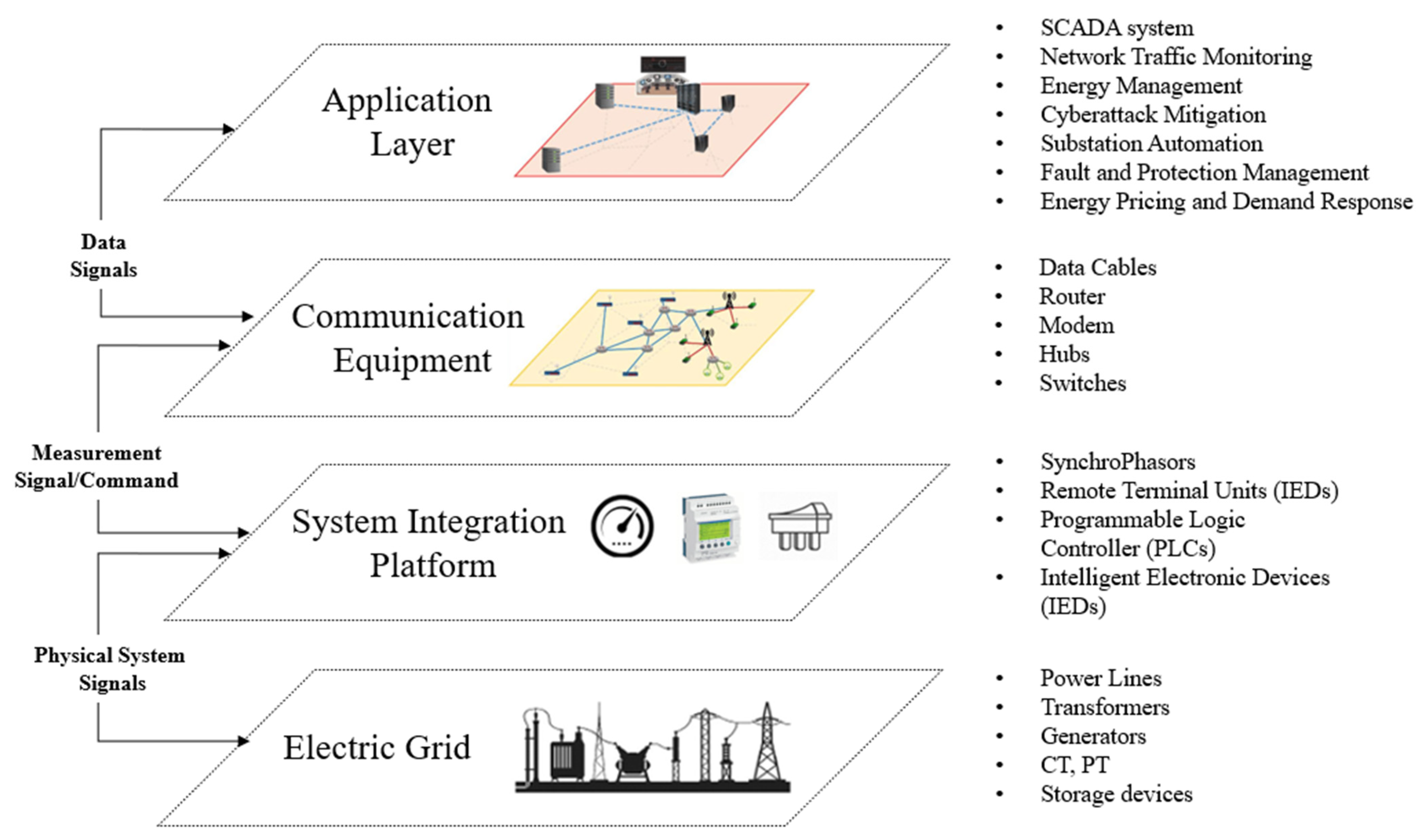
Figure 2.
CPS testbed at the TTU facility: (a) communication architecture; (b) hardware components.
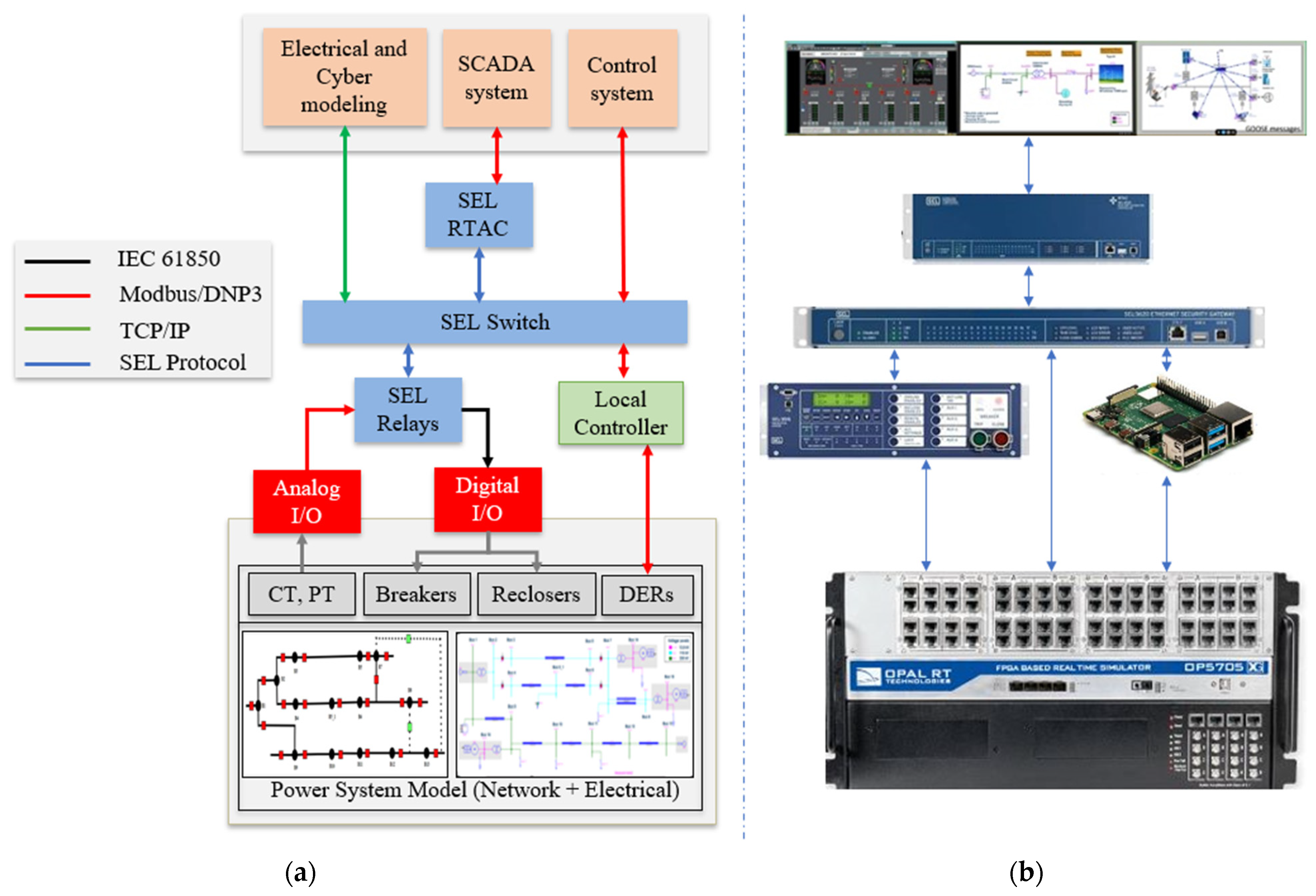
Figure 3.
Distribution system testbed topology.
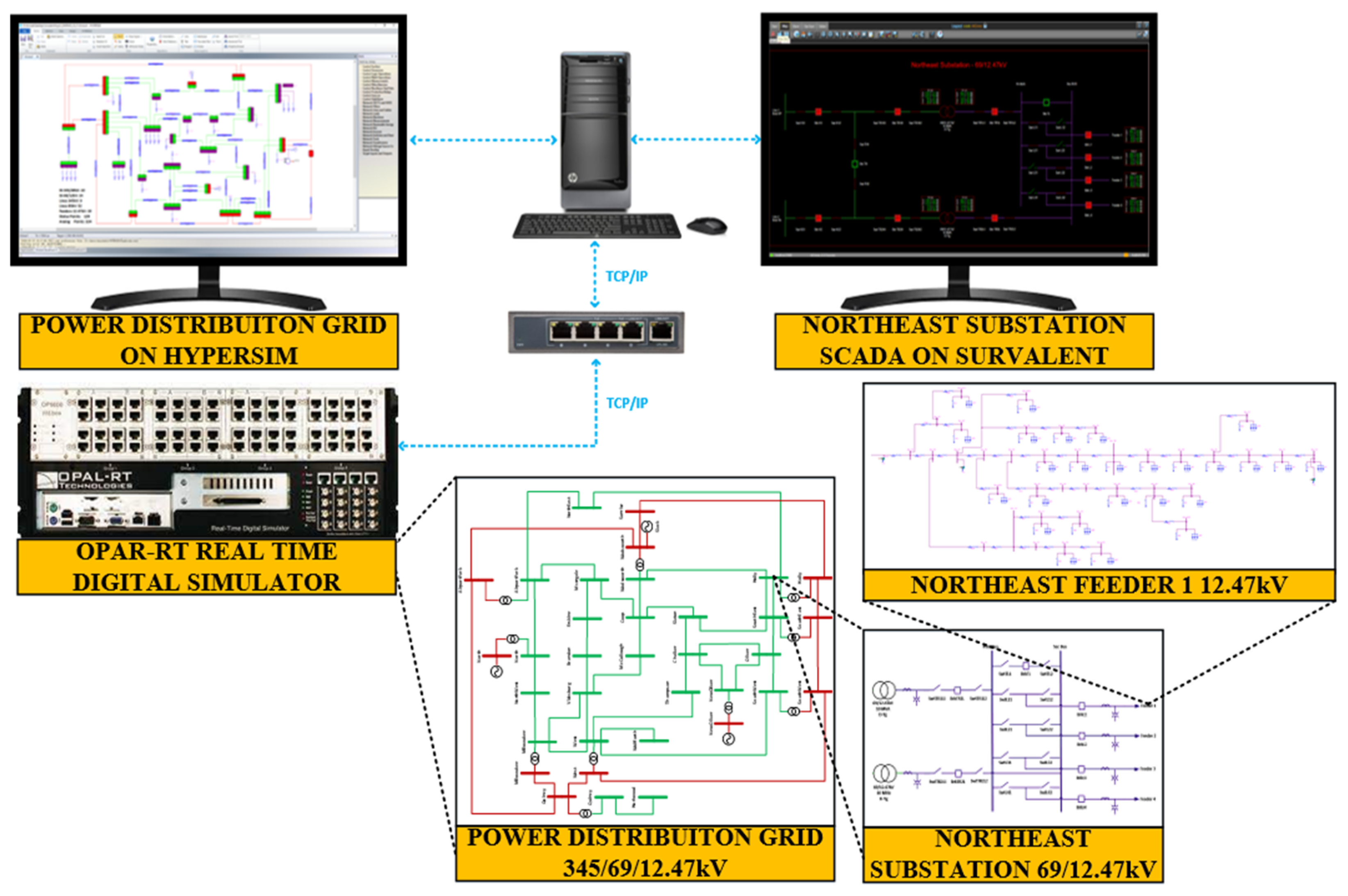
Figure 4.
Northeast substation: (a) one-line diagram; (b) HYPERSIM modeling; (c) Survalent GUI.
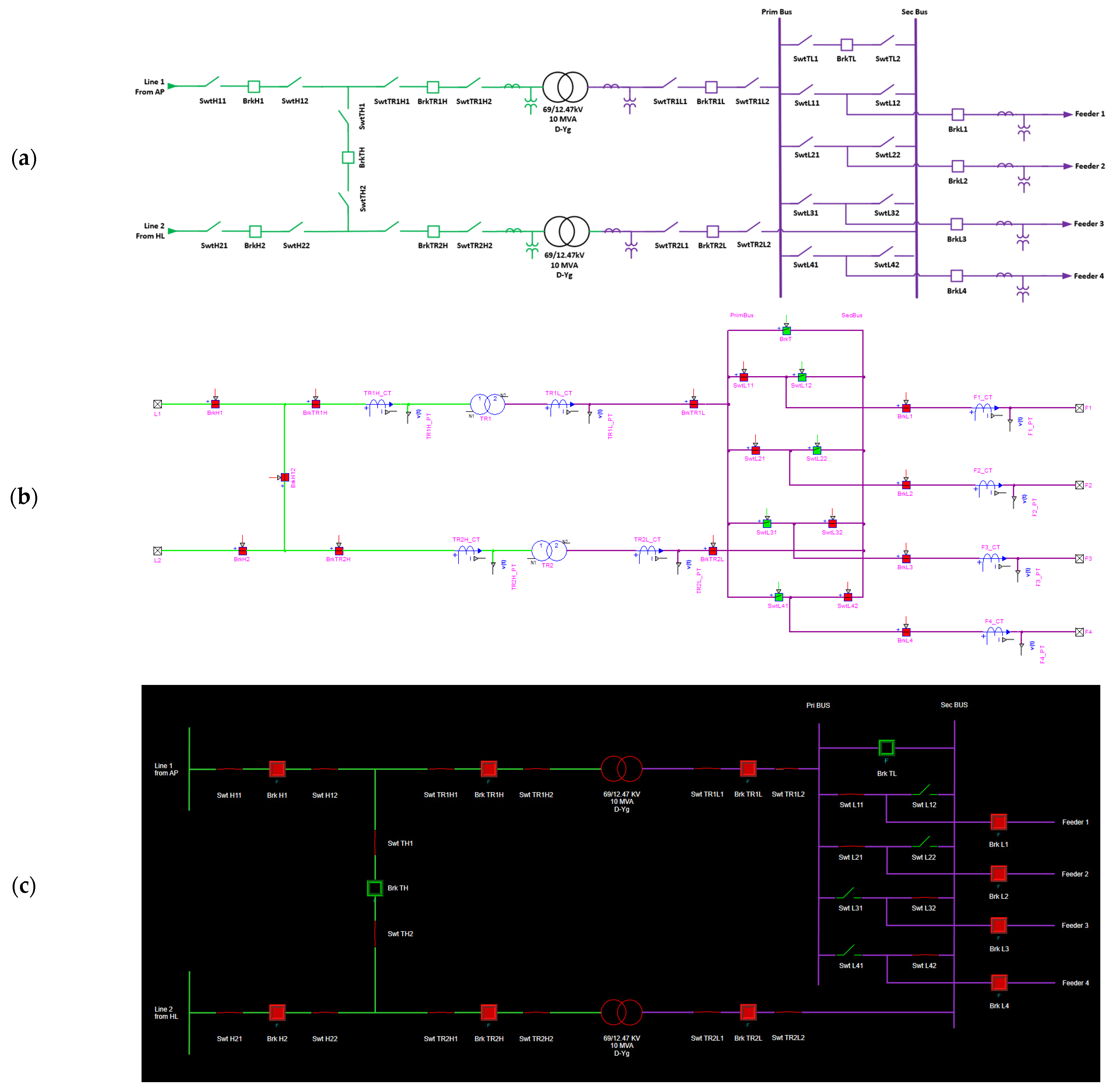
Figure 5.
AC recloser generic operation.
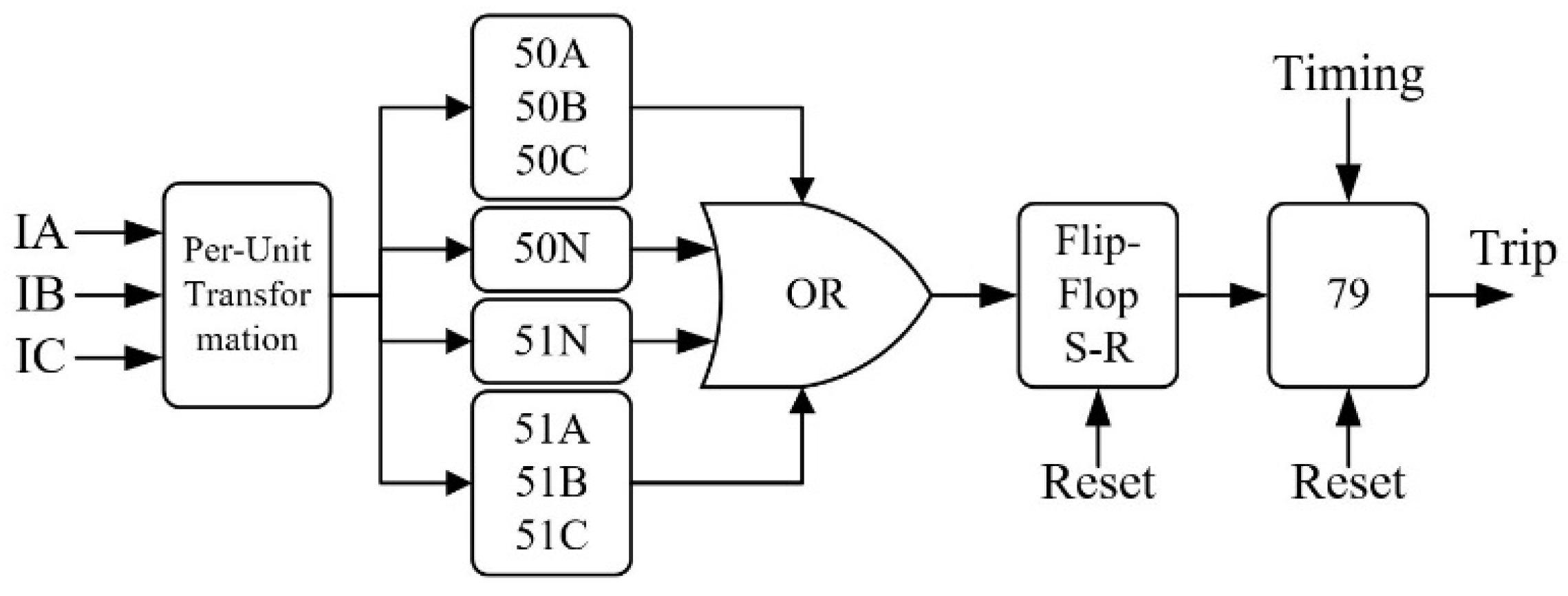
Figure 6.
NE feeder’s 50 and 51 protection coordination.
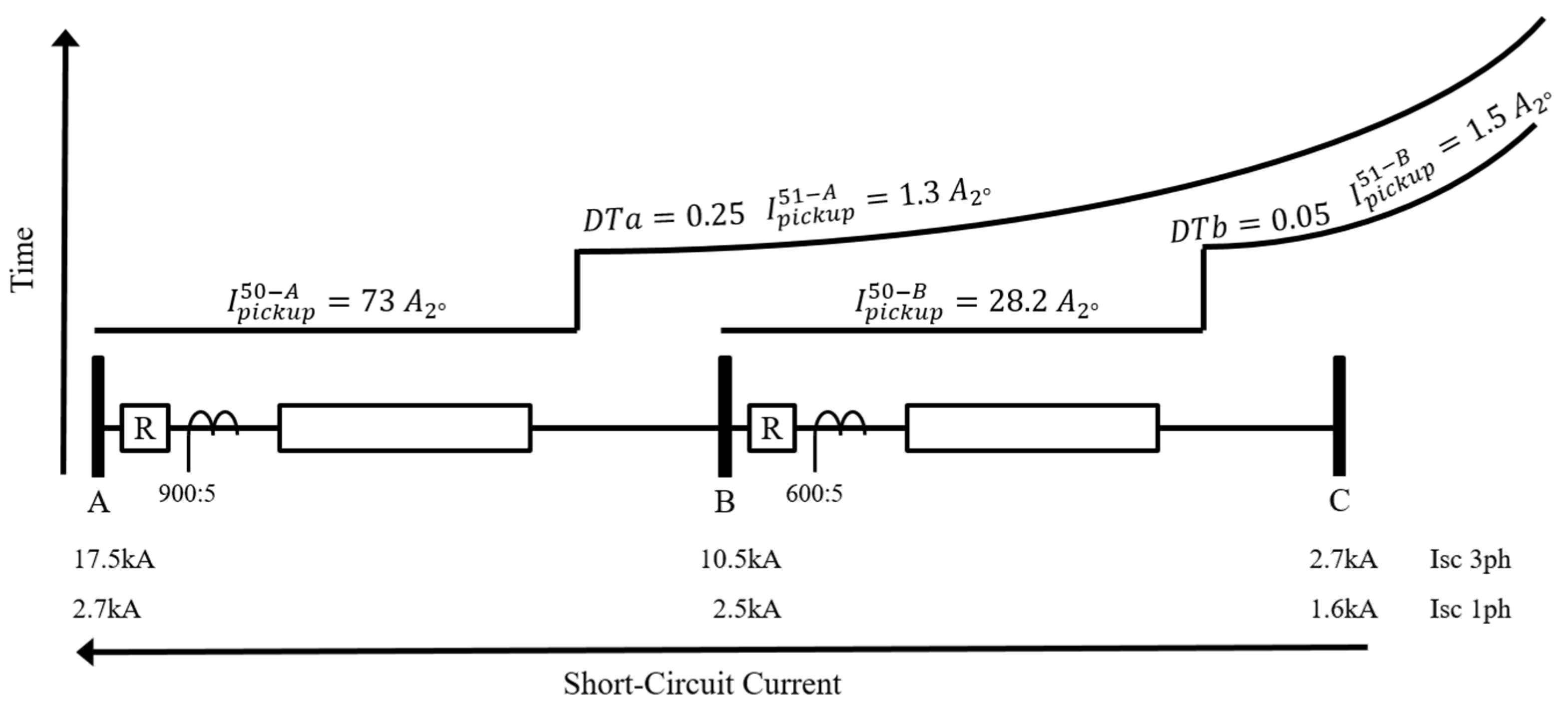
Figure 7.
operations under (a) permanent fault and (b) temporary fault.

Figure 8.
status (a) before fault and (b) after lockout.
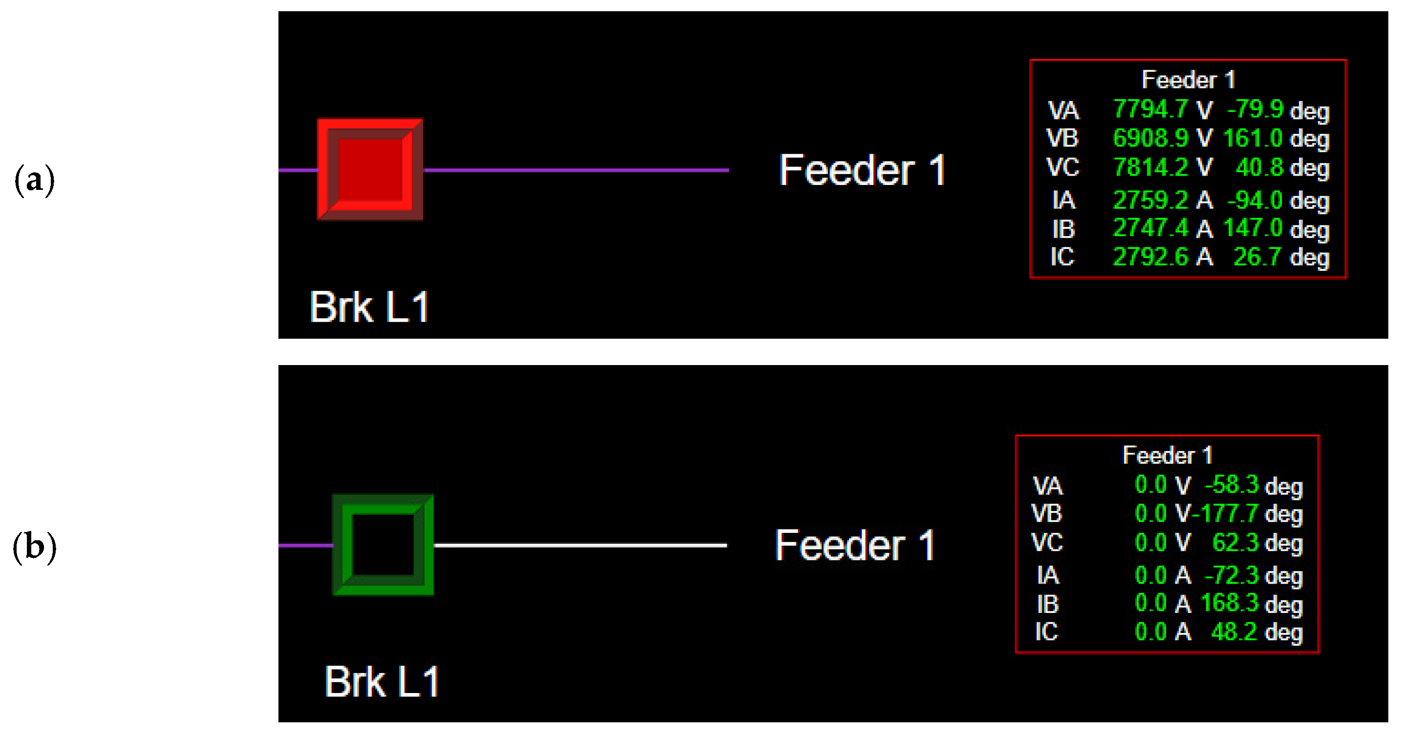
Figure 9.
Diagrammatic representation of system variables under attack.

Figure 10.
Quantity of messages: (a) sent; (b) received with DoS attack.

Figure 11.
Quantity of messages: (a) sent; (b) received with the jamming attack.

Figure 12.
The co-simulation testbed architecture of the cyber–physical system.
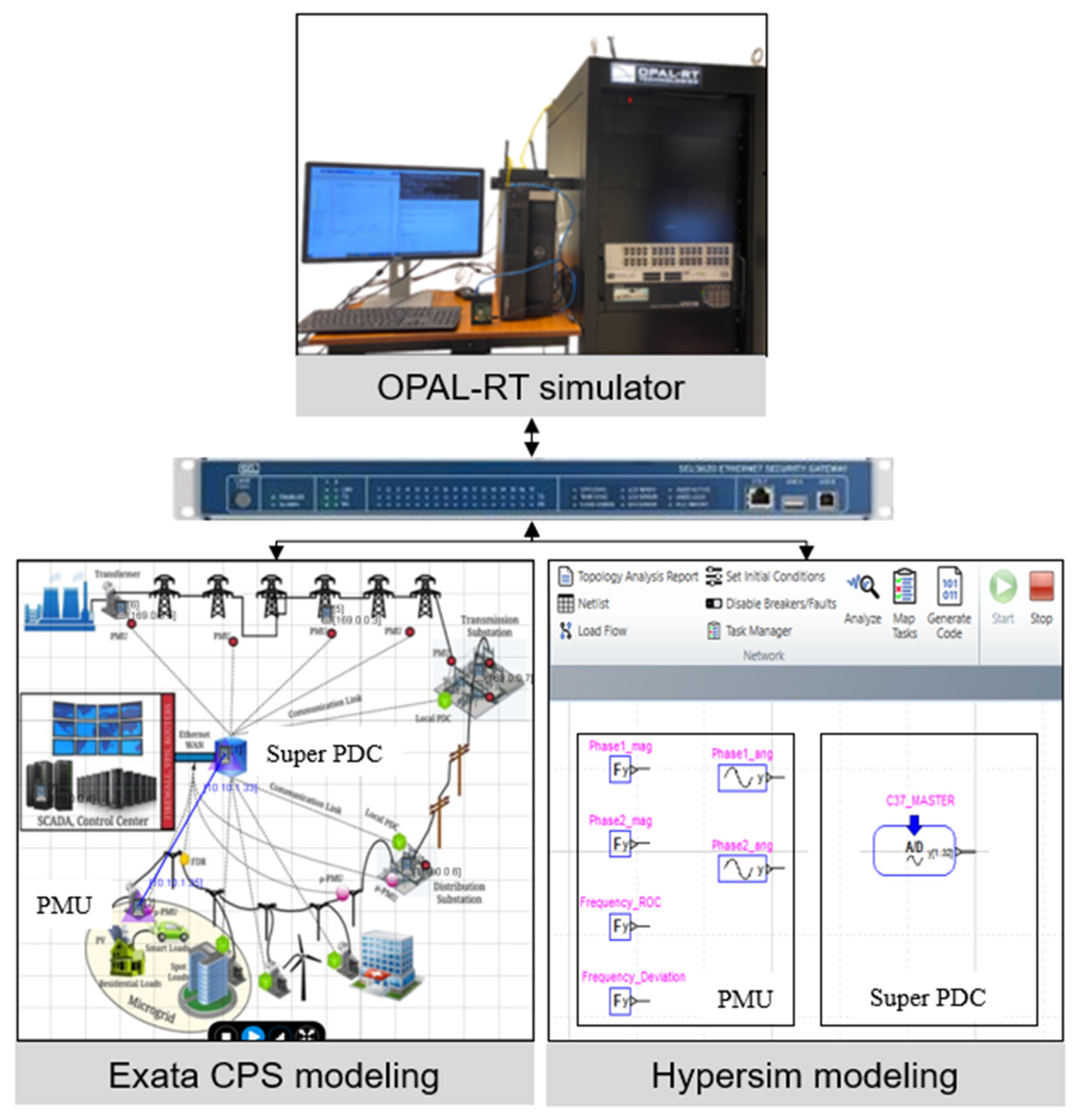
Figure 13.
Comparison of the phase angle between PDC and PMU: (a) without delay attack; (b) with delay attack.
Figure 13.
Comparison of the phase angle between PDC and PMU: (a) without delay attack; (b) with delay attack.
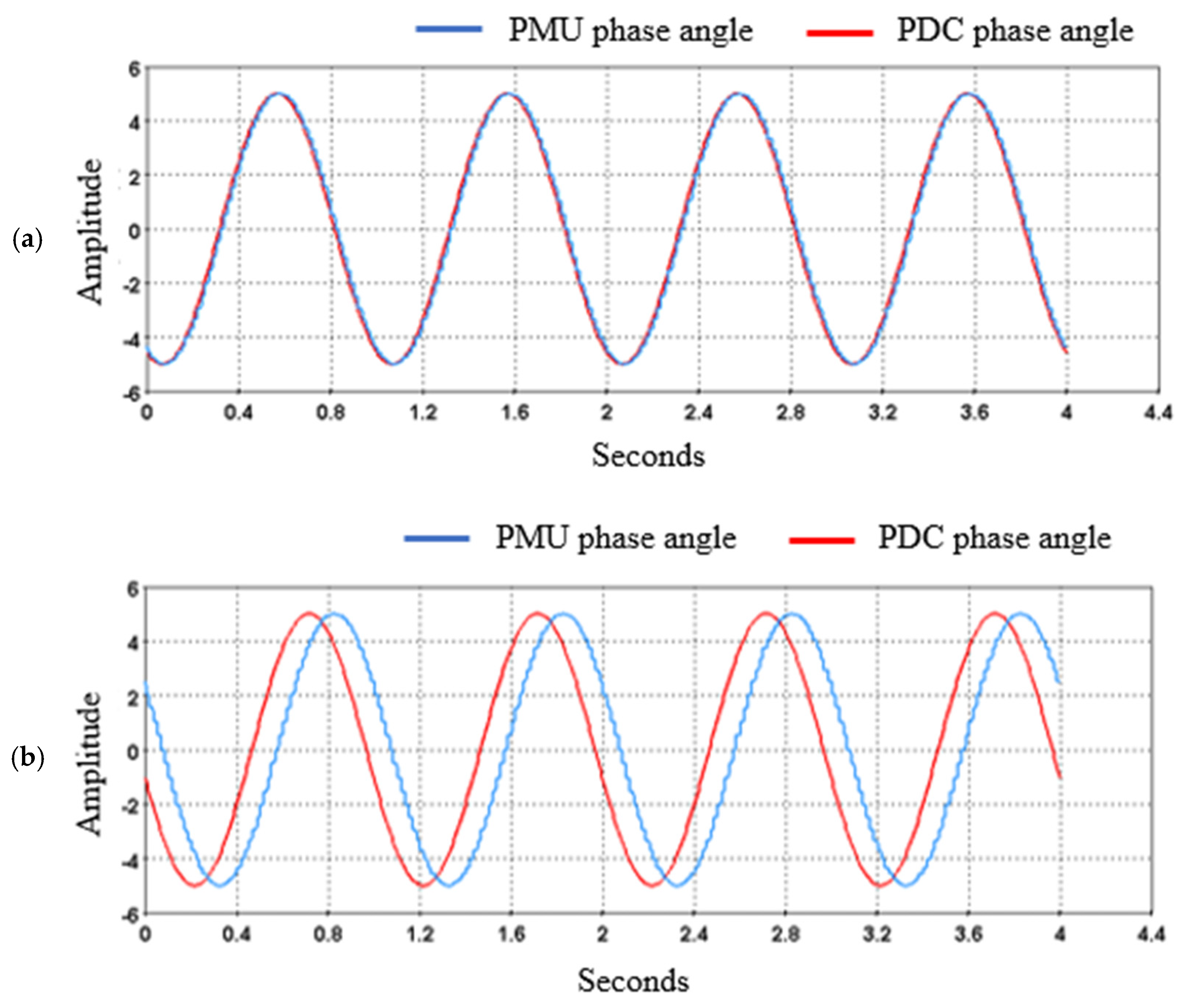
Figure 14.
Comparison of the phase angle between PDC and PMU: (a) without multiplication attack; (b) with multiplication attack.
Figure 14.
Comparison of the phase angle between PDC and PMU: (a) without multiplication attack; (b) with multiplication attack.
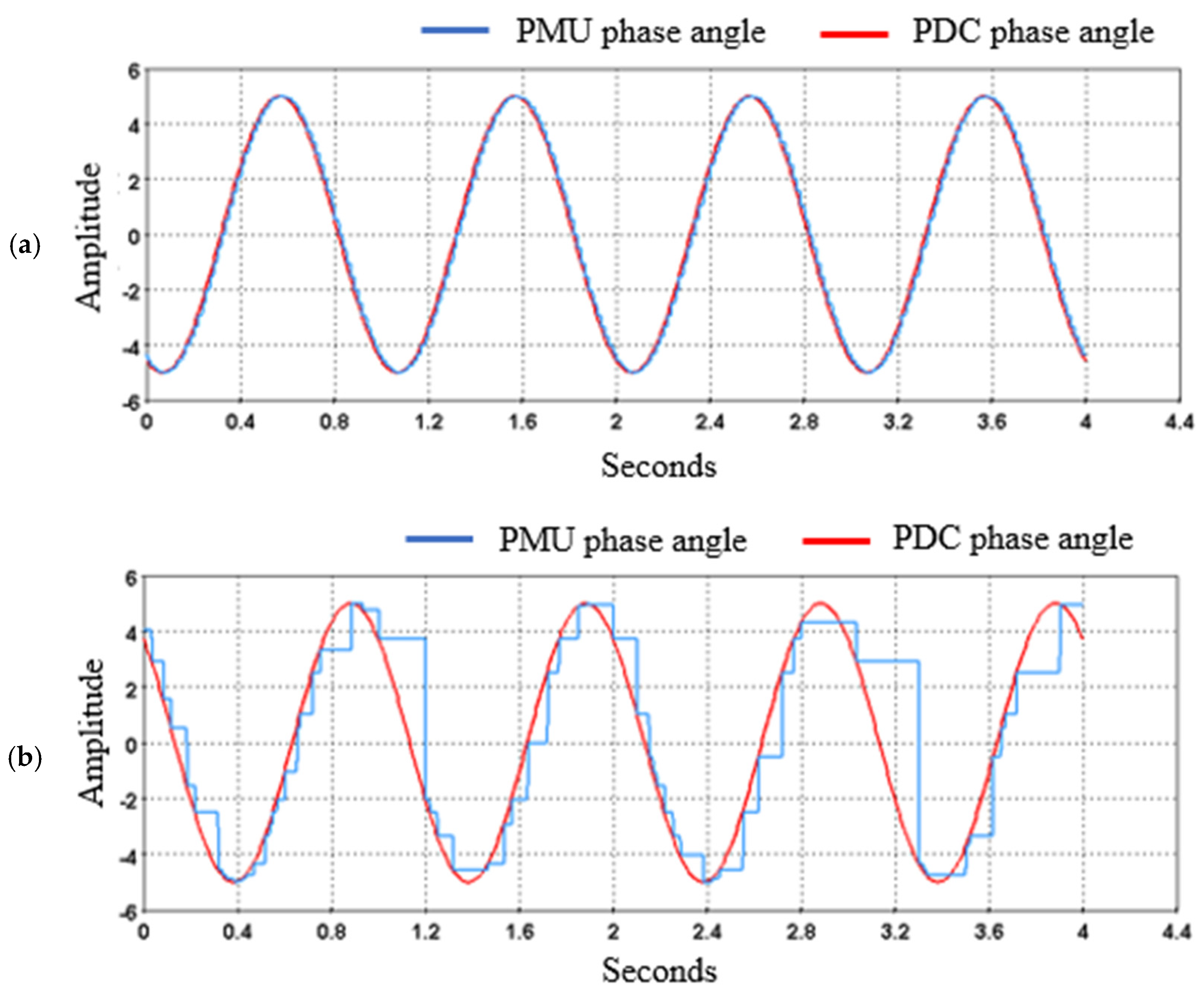
Figure 15.
Wind farm and power system physical model in HYPERSIM.

Figure 16.
Schematic of the wind farm and power system communication model in EXata CPS.
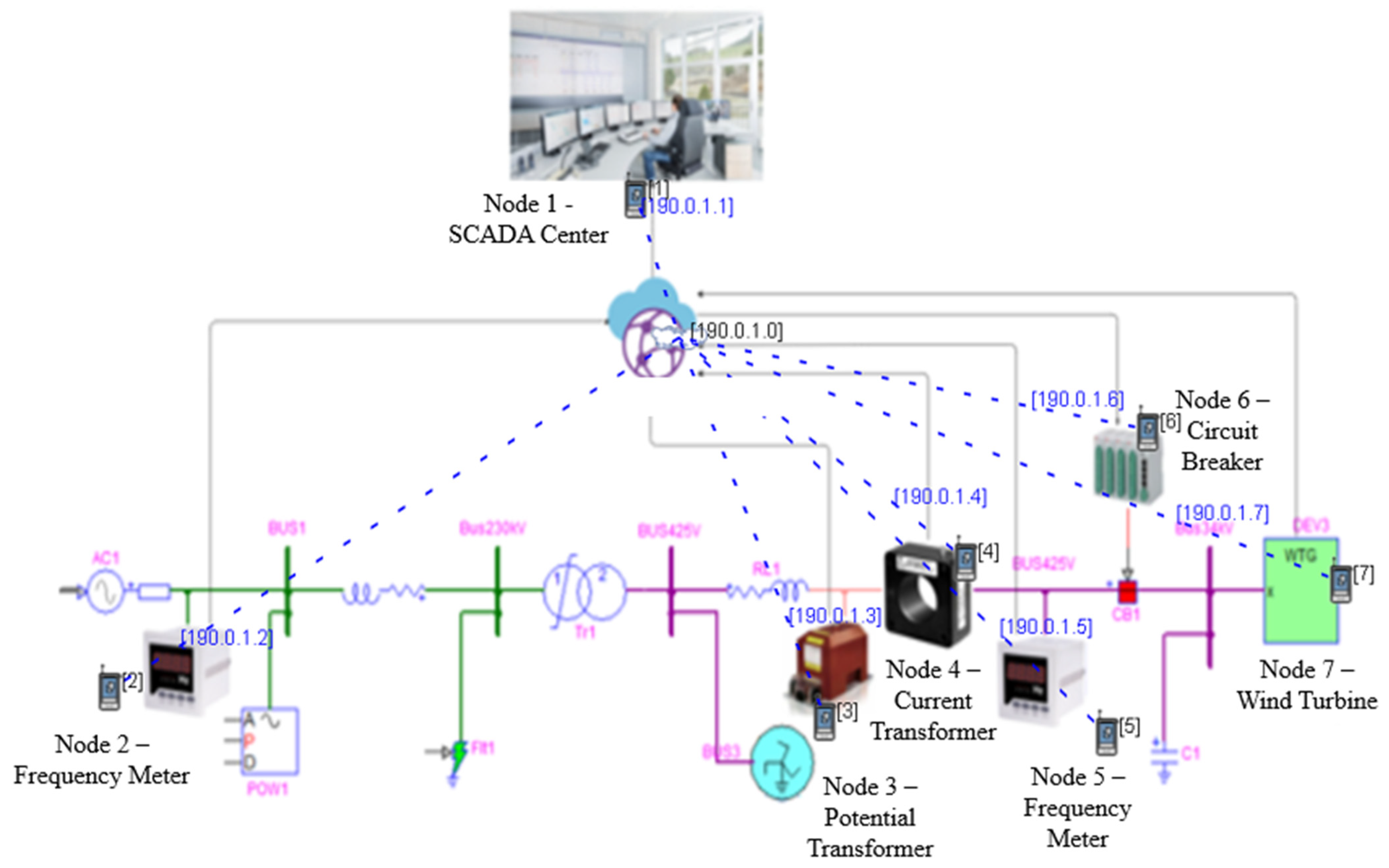
Figure 17.
Comparison of wind speed and frequency: (a) without attack; (b) with attack.
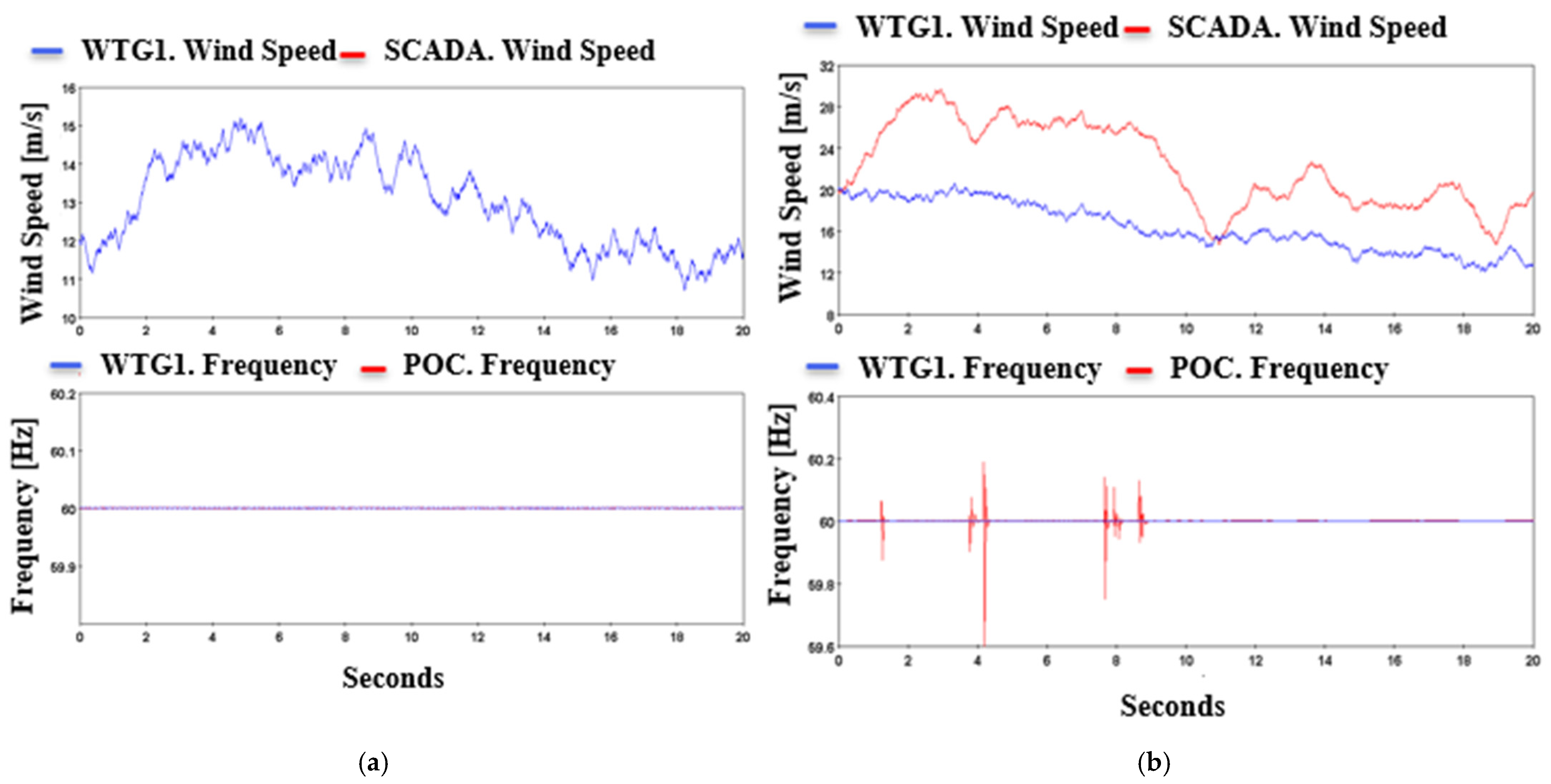
Figure 18.
Comparison of the active and reactive power: (a) without attack; (b) with attack.


Table 1.
Most recent studies on CPS testbeds for power system applications.
| Literature | Year | Research Topic | Novelty | Co-Simulation | Real Time | IDS |
|---|---|---|---|---|---|---|
| [11] | 2015 | The impact of cyberattacks on power grids was studied in a simulated power network and an emulated communication network. | Reconfigurable testbed | No | No | No |
| [39] | 2015 | Development and application of real-time testbed for CPS | Real-time simulation | No | Yes | No |
| [18] | 2016 | ICS for the deployment of cybersecurity methods was studied using different attack scenarios. | Emphasizes the optimal distribution of security protection in large legacy ICSs | No | No | No |
| [40] | 2018 | Detection of stealthy cyberattacks in the smart grid | Study of hybrid and stealthy attacks in a power system | No | Yes | Yes |
| [41] | 2020 | CPS testbed for wind energy systems | HIL simulation | Yes | Yes | No |
| [42] | 2021 | CPS testbed studying MITM attack detection and defense | FDIA and MITM attacks simulated in the data link layer | No | No | Yes |
| [43] | 2021 | Real-time co-simulation testbed for inverter-based microgrids | Use of SEL-3530 with OPAL-RT | Yes | Yes | No |
| [44] | 2021 | A real-time CPS testbed to study cyber threats and risk assessments | Use of EXata CPS for attack simulation in real time | Yes | Yes | No |
Table 2.
Relay buses’ current levels.
| Bus | [A] | [kA] | [kA] |
|---|---|---|---|
| A | 115 | 17.5 | 2.7 |
| B | 90 | 10.5 | 2.5 |
| C | 43 | 2.7 | 1.6 |
Table 3.
General configuration for standalone attacks.
| Property | Value | Property | Value |
|---|---|---|---|
| Attack type | DOS | Attack type | Jammer |
| Victim node | Node 2 | Jammer node | Node 15 |
| Victim IP | 10.10.1.33 | Start time | 1 |
| DOS attack type | Basic attack | End time | 25 |
| Victim port | 7200 | Scanner index | 0 |
| Configure | Interval | Jamming power | Power (dBm) |
| Interval | 0.1 s | Power | 100 dBm |
| Duration | 30 s | Silent jammer | Yes |
| Ramp-up time | 0 s | Ramp-up time | 0 s |
| Data rate | 1 Mbps |
Table 4.
General configuration for packet multiplication and delay attacks.
| Property | Attack 1 | Attack 2 |
|---|---|---|
| Attack type | Packet multiply attack | Delay attack |
| Attacker node | Node 2 (PDC node) | Node 2 (PDC node) |
| Layer type | Network | Network |
| Destination port | 7200 | 7200 |
| MODP attack type | Multiply | Delay |
| Value | 2 | 100 ms |
| Number of bytes | 2 | - |
| Start byte | 112 | - |
Disclaimer/Publisher’s Note: The statements, opinions and data contained in all publications are solely those of the individual author(s) and contributor(s) and not of MDPI and/or the editor(s). MDPI and/or the editor(s) disclaim responsibility for any injury to people or property resulting from any ideas, methods, instructions or products referred to in the content. |
© 2023 by the authors. Licensee MDPI, Basel, Switzerland. This article is an open access article distributed under the terms and conditions of the Creative Commons Attribution (CC BY) license (https://creativecommons.org/licenses/by/4.0/).
Share and Cite
MDPI and ACS Style
Chamana, M.; Bhatta, R.; Schmitt, K.; Shrestha, R.; Bayne, S. An Integrated Testbed for Power System Cyber-Physical Operations Training. Appl. Sci. 2023, 13, 9451. https://doi.org/10.3390/app13169451
AMA Style
Chamana M, Bhatta R, Schmitt K, Shrestha R, Bayne S. An Integrated Testbed for Power System Cyber-Physical Operations Training. Applied Sciences. 2023; 13(16):9451. https://doi.org/10.3390/app13169451
Chicago/Turabian StyleChamana, Manohar, Rabindra Bhatta, Konrad Schmitt, Rajendra Shrestha, and Stephen Bayne. 2023. "An Integrated Testbed for Power System Cyber-Physical Operations Training" Applied Sciences 13, no. 16: 9451. https://doi.org/10.3390/app13169451
Note that from the first issue of 2016, this journal uses article numbers instead of page numbers. See further details here.