
Kinematic Analysis and Virtual Prototype Simulation of the Thrust Mechanism for Shield Machine


1
Key Laboratory of Urban Underground Engineering, Ministry of Education, Beijing Jiaotong University, Beijing 100044, China
2
School of Civil Engineering, Beijing Jiaotong University, Beijing 100044, China
3
Suzhou Rail Transit Line S1 Co., Ltd., Suzhou 215300, China
*
Author to whom correspondence should be addressed.
Appl. Sci. 2022, 12(3), 1431; https://doi.org/10.3390/app12031431
Submission received: 13 December 2021
/
Revised: 22 January 2022
/
Accepted: 24 January 2022
/
Published: 28 January 2022
(This article belongs to the Special Issue Tunneling and Underground Engineering: From Theories to Practices)
Abstract
:The hydraulic thrust system of the shield machine is used for driving forward and pose adjustment. It is of great significance to figure out the thrust mechanism and motion characteristics of the shield machine to ensure the safety of tunnel excavation. This study aims to develop a model to explore the influence of thrust cylinder advancement on the motions of the shield machine. Firstly, the study carried out mechanism analysis of the thrust mechanism for the shield machine and established a method to describe the position and attitude of the shield machine during the tunneling process by the homogeneous transformation matrix. Then, a new inverse kinematic model was proposed to quantify the relationship between the telescoping movements of cylinders and shield machine motions, and the Jacobian matrix was derived to solve the instantaneous kinematics analysis. Furthermore, a virtual prototype model was developed to simulate the kinematic behavior of the shield machine and validate the accuracy of the kinematic model. The model provides the basic constraint relations for the practical position control system and lays a strong foundation for the dynamic model and automatic trajectory tracking control of shield machines for future studies. Based on the proposed model, the displacement, velocity, and acceleration of cylinders that drive the shield machine to the target motions can be solved exactly. It can provide a reference for the pose control of the shield machine during the practical shield tunneling.
1. Introduction
Characterized by high security, environmental friendliness, and automation, the shield tunneling method serves as an effective method for excavating tunnels and has found wide application in tunnel construction [1,2,3]. As one of the major systems of shield machines, the hydraulic thrust system composed of a series of circular-distributed thrust cylinders plays a key role during shield tunneling operation. It performs the critical tasks of driving forward and pose (position and attitude) adjustments by controlling thrust cylinder expansion or contraction, which ensures the trajectory of the shield machine tracks the tunnel design axis well [4,5,6]. During tunnel construction, improper pose and axis deviation make segment assembly difficult, and it can easily cause tunnel quality problems such as segment damage and leakage. It may even make cause the existing tunnel that was assembled to be abandoned, resulting in waste of money and construction time.
Research on the kinematic behavior of the shield machine is the basis of realizing the accurate control of the shield pose [7]. Some works have been done around the shield behavior, only based on the data from the shield guide system [8,9]. However, this research, lacking the kinematic principles of the shield thrust mechanism, have difficulty in solving the problem of pose control.
With the development of electro-hydraulic proportional control and electro-hydraulic servo control technology, the control mode based on displacement feedback control mode and force-displacement composite control mode is widely used [10]. Several pieces of research have proved that displacement control mode can be used to achieve precise control of shield cylinder displacement, and it can control the cylinder movement more accurately to adjust the shield pose, avoiding lag and inaccuracy of force control [11,12]. These pieces of research make it possible to study pose control of shield machines based on the kinematic model of the thrust system.
The shield thrust mechanism is a typical multiple input multiple output (MIMO) redundant parallel mechanism with six degrees of freedom, and there is a strong coupling between position degrees of freedom and attitude degrees of freedom. Kinematic analysis of thrust mechanism needs to be solved urgently to explore the motion laws of shield machine, especially the mapping relationship between the cylinder branch chain motions of shield thrust mechanism and the motions of shield machine, which is the key to motion control of the shield and close tracking the tunnel design axis.
Kinematics of a mechanism can be generally divided into two categories: forward kinematics and inverse kinematics. The forward kinematics focuses on solving the motion of the end effector by given geometric parameters and joint variables, through which we can predict the actual trajectory of the end effector [13,14]. Conversely, inverse kinematics provide closed-form solutions to determine appropriate joint parameters to make the end effector reach the target pose [15], which can provide accurate kinematic equations for real-time control and trajectory tracking of mechanism [16,17,18]. Therefore, the inverse kinematics is more adaptable than the forward kinematics in improving the control accuracy of the actual trajectory of the shield machine [15,19,20]. Once the motions of thrust cylinders are calculated using inverse kinematics, a motion profile can be generated using the Jacobian matrix to move the shield machine from the initial to the target pose. In general, the usual methods used to solve the inverse kinematics include numerical methods and analytical methods (closed-form solutions). Due to the complexity and non-linearity of the inverse kinematics, the numerical iteration method is always used to solve it. However, the numerical solution needs more computation than the analytical solution, so it is not suitable for occasions with high real-time requirements [16,20].
To date, only a few pieces of research have studied the inverse kinematics of shield thrust mechanism by the analytical solution. Wang et al. [7] proposed a mathematical method for determining the target motions of the thrust cylinders and applied it in determining the target motions of the thrust cylinders. With the help of these mathematical models, the application range of the automatic pose and trajectory system is greatly enlarged. He et al. [21] carried out the kinematic modeling of the shield thrust mechanism for the demand of the shield machine’s position solution with the kinematics analysis method of the parallel mechanism. The existing kinematic models provide the basic constraint relations for the practical position control system but restrict their applicability for the following reasons. First, most of the equations in the inverse kinematic model are implicit equations, in which some motion parameters, like sway angle and sway angular velocity of cylinders, are difficult to determine and control in the engineering practice. Second, the respective relations between attitude angles of shield machine and angular velocity and angular acceleration have not been explored. Finally, the explicit solutions for angular velocity and angular acceleration of the shield machine are not solved.
Motivated by these considerations, this study aims to propose a new analytical solution to solve the inverse kinematics of shield thrust mechanism, in which all equations are explicit equations, and all the parameters are easy to determine. Based on the proposed model, the displacement, velocity, and acceleration of cylinders that drive the shield machine to the target motions can be solved exactly. These solutions provide the basic constrain relations for practical position control system. Moreover, a virtual prototyping model was developed to simulate the kinematic characteristics of the shield machine and validate the theoretical analysis. The inverse kinematic model established in the paper lays a crucial foundation of shield thrust mechanism design, workspace analysis, and trajectory tracking control. In particular, the analytical solutions of the inverse kinematics can be embedded into the hardware for real-time application to solve the motion state of the thrust cylinders when the shield machine is tracking a target trajectory, so as to achieve the purpose of real-time control of the shield pose.
In this study, the innovation points are as follows:
- Detailed mathematical modeling and analysis of the shield thrust mechanism are performed to elucidate the pose adjustment principle.
- A new explicit analytical solution to solve the inverse kinematics of the shield thrust mechanism was proposed, to describe the relationship between the cylinders and TBM motions.
- A virtual prototype model of the shield thrust mechanism was developed to simulate the kinematic behaviors of the shield machine and validate the accuracy of the proposed kinematic model.
2. Description of Thrust Mechanism
The shield hydraulic thrust system performs the critical tasks of driving forward and pose adjustment under the resistance from soil. The thrust system is composed of a series of hydraulic cylinders, and these cylinders are generally divided into four groups: left, right, up, and down. Thrust cylinders in each group share the same pressure, and the pressure can be set separately in different groups. The combined effect of internal and external forces applied on the cylinders can contribute to differential displacements of cylinders, even in the same group. Thus, the shield machine may be pushed to advance or deflect in a certain direction.
The thrust system is a typical redundant mechanical system with multiple inputs from the parallel thrust cylinders. From the perspective of the mechanism, the front end of hydraulic cylinders is hinged, with the backplane of the middle shield through a spherical joint, and the rear end of the hydraulic cylinder is attached to the assembled segment ring through a boot. When tunneling, the shield machine is pushed forward by the reverse thrust provided by cylinder extension against the segment ring. Therefore, the thrust system can be simplified as an n-SPS equivalent parallel mechanism (n: number of cylinders; S: spherical joint; P: prismatic pair).
3. Kinematic Analysis
3.1. Principle of Pose Calculation
3.1.1. Coordinate System Description and Coordinate Transformation
The shield machine has six degrees of freedom when tunneling in soil, three for position and three for attitude. Two coordinate frames were defined to describe the pose of the shield machine. The global coordinate frame {A-xyz} was attached to the rings and the x-axis was in the direction of the ring axis. The origin of the base coordinate system was selected as the distributing center of the gripper shoes of cylinders. The local coordinate frame {B-xByBzB} moving with the TBM was attached to the backplane of the middle shield, and origin B is the distributing center of front hinges of cylinders. The xB-axis is in the direction of the machine axis. In the initial stage, the corresponding axes of the two frames were aligned. The diagram of the shield driving mechanism and layout of coordinate systems are shown in Figure 1.
In this paper, the homogeneous transformation matrix, characterized by solving the position and attitude simultaneously, was employed to express the transformation relationship between two coordinate frames {A} and {B}, and it proved to be convenient for mechanism design and kinematics solution [20,22]. The matrix describes the position and attitude of the coordinate frame {B} with respect to the coordinate frame {A}, from which the pose of the shield machine was also obtained. The is described in Equation (1) [23]:
where denotes the rotation matrix from the coordinate frame {B} to the coordinate frame {A}. denotes translation vector from point A to point B, and it represents the position of coordinate system {B} located in coordinate system {A}.
In Figure 1, LBC denotes the distance from the center of the cutter head to point B; L denotes the length of cylinder sleeve; li denotes the stroke of the ith cylinder; R denotes the internal radius of shield machine; R0 denotes the radius of the distribution of the cylinders; Δri denotes the shield tail gap approaching the ith cylinder. The shield diameter was assumed to be a constant along the longitudinal direction in this study. In this model, the size of spherical joints were so small relative to other parts that it could be neglected in the calculation.
Convention: the coordinates of parameters in this paper were automatically selected as homogeneous coordinates or ordinary coordinates to satisfy the operation.
3.1.2. Rotation Matrix and Euler Angles
The Euler angles (Z-Y-X) in robotics are adopted to describe the attitude of the shield machine relative to the coordinate frame {A}. Thus, the rotation matrix can be written as Equation (2) [25,26]:
where denotes roll angle, pitch angle, and yaw angle of the shield machine, respectively; c and s denote cosine and sine, respectively.
An arbitrary vector, , in coordinate frame {B} can be represented as in coordinate frame {A}.
Therefore, any pose of the shield machine can be described by a matrix, , containing six unknown pose variables,.
3.2. Position and Attitude Analysis
The positions of spherical joints Bi and Ai relative to their respective coordinate frames {B} and {A} can be expressed by the constant vectors, and , which can be de described in homogeneous coordinates as:
The layout diagram of thrust cylinders is shown in Figure 2, and can be calculated as follows:
where denotes the radius of the distribution of the cylinders; η denotes the angle between the ith hydraulic cylinder and the y-axis; i = 1, 2, … n.
According to the geometric characteristics of the parallel mechanism and the homogeneous transformation matrix, the position vector of Bi with the reference in global frame {A} can be described as:
Then, the following relationship can be established by using the vector construction method,
where denotes the unit direction vector of the ith hydraulic cylinder branch chain in the global frame {A}.
Considering Equations (6) and (7), the stroke of the ith cylinder under a given pose of shield machine can be obtained as:
Thus, the strokes of cylinders can be determined from Equation (8) when the structural dimensions of the thrust mechanism and pose parameters are given.
3.3. Inverse Velocity Solving and Jacobian
The speed of the thrust system determines the propulsive efficiency of the shield machine, so it is important to perform velocity analysis of the thrust system. The previous research on speed control of the thrust system mainly focused on the elongation or shortening speed control of a certain group of cylinders based on electro-hydraulic control. However, the thrust system controls the changes in position and attitude of the shield machine. The change speed in the shield pose includes both the forward speed and the rotating speed component. Therefore, the elongation or shortening speed of cylinders is insufficient to describe the pose change speed of the shield machine. The velocity analysis model of the thrust system should be established from the equivalent mechanism.
3.3.1. Velocity Analysis
Equation (9) can be derived easily according to Equations (6) and (7),
Conduct a dot multiply by itself operation for both sides of Equation (9),
Differentiate t on both sides of Equation (10),
where
where and denote the velocity vector and angular velocity vector of shield machine relative to the global coordinate frame {A}, respectively.
Therefore, Equation (14) can be derived by substituting Equations (12)–(14) to Equation (11).
According to the Lagrange formula,
Equation (15) can be further described as
Equation (17) can be written in matrix form as
where
The relationship between the extension velocity of cylinders and the generalized velocity of the shield machine can be described explicitly as
where is an n-dimensional column vector composed of the extension velocity of each cylinder; is a 6-dimensional column vector composed of the velocity vector, , and angular velocity vector, ; is the Jacobian matrix for the parallel mechanism of shield machine, and they can be expressed as:
The Jacobian matrix, , not only shows the mapping relationship between the joint space of each branch chain (thrust cylinder) and the workspace of the shield machine, but also reveals the linear mapping relationship between the extension velocity of cylinders and the generalized velocity of the shield machine. Most importantly, Equation (22) involves only several easily accessible parameters, and the shield machine velocity can be easily determined using this equation. It will contribute significantly to the precise control of the speed of the shield machine during the tunneling process.
3.3.2. Angular Velocity and Rate of Euler Angular
For any type of Euler angle, the angular velocity is not simply equal to the rate of Euler angles, known as:
Equation (14) can be written as:
Considering the orthogonality of the rotation matrix, the following can be derived:
where represents the skew-symmetric matrix of the angular velocity vector, and it is expressed as:
Therefore, the angular velocity vector can be solved by the following three independent equations:
where rij corresponds to the element in row i and column j of the rotation matrix .
Equation (27) can be written into matrix-form as:
where is solved as:
The nonlinear differential equation of Euler angles in the fixed coordinate system can be solved as:
where
3.4. Inverse Acceleration
Considering the thrust system characterized by large inertia and time delay, the influence of inertia on the trajectory of the shield machine must be considered. Moreover, acceleration modeling is the premise of dynamic modeling and speed control.
3.4.1. Acceleration Analysis
Differentiate both sides of Equation (22) with respect to time.
where is an n-dimensional column vector composed of the extension acceleration of each cylinder; is a 6-dimensional column vector composed of acceleration vector and angular acceleration vector, , and they can be expressed as:
Differentiate both sides of Equation (22) with respect to time, and the result can be solved as:
3.4.2. Angular Acceleration and Rate of Euler Angular
The angular acceleration, , is the first derivative of angular velocity, . Differentiate both sides of Equation (28) with respect to time, and the angular acceleration can be solved as:
where
Figure 3 shows the whole calculation process for the inverse kinematic solutions of the shield thrust mechanism. On this basis, the calculation program was compiled by MATLAB R2017b to solve the motion behaviors of the cylinders of the shield thrust mechanism when the shield machine was tracking a target trajectory.
4. Virtual Prototype Modeling and Simulation
As a widely used modeling technology, the virtual prototype model created by program MSC. ADAMS (automatic dynamic analysis of mechanical systems) can reflect the characteristics of actual products, including appearance, spatial relationship, kinematics and dynamics characteristics [8,27,28,29,30,31]. With the help of this technology, the mechanical system model can be built on the computer, accompanied by 3D visualization processing to simulate the kinematic characteristics of the system in the real environment [32,33,34]. Therefore, the virtual prototype modeling of the shield machine was built up in Adams/View to simulate the kinematic behavior of the shield machine and validate the analytical model proposed.
4.1. Structural Parameters for the Simulation Model of the Shield Thrust Mechanism
The structure and dimension information of the shield machine used in the simulation are shown in Table 1.
As shown in Figure 4, the thrust cylinders are divided into four groups (Group-A, Group-B, Group-C, and Group D).
4.2. Modeling Process and Model Assumptions
The prototype model was built up in ADAMS 2017, as shown in Figure 5. The detailed modeling process was as follows:
- (a)
- Firstly, every part of the shield machine was established in Solid Works software, and then assembled into an assembly model based on the relative position relationships between parts. According to the assembly of the three-dimensional specific model, it was saved in the format of parasolid (*.x_t) and imported into Adams.
- (b)
- Assigned attributes to parts of shield machine. Established the constraints, joints between parts, boundary conditions, motions, and measurements in Adams.
- (c)
- A fixed pair was set between the segment and the ground. One sliding pair and two spherical pairs were used on each cylinder branch chain according to the motion of the cylinders.
- (d)
- The “general point motion” was used to plan the trajectory of the shield machine. The “general point motion” was added at Marker B (the distributing center of front hinges of cylinders) and the trajectory parameter equation of the marking point was set as:
- (e)
- Establish the corresponding measurements to observe the following variables: of Marker B with regarding to Marker A (the distributing center of the gripper shoes of cylinders), and of all thrust cylinders.
- (f)
- Set the duration for simulation as 50 s, so that the driving distance of the shield machine was exactly 1500 mm. Set the simulation step size as 1 s, that is, the numerical model will be calculated 50 times in total.
The position and attitude should keep changing continuously and smoothly when the shield machine is advancing, and satisfy the coordination of position and attitude with consideration of the coupling. Moreover, the target pose point on the desired trajectory should be within the workspace of the shield thrust mechanism. The parametric equations of driving function for target pose were solved based on Equation (37) and further plotted, as shown in Figure 6.
Due to the complexity of the shield thrust system, it is impossible to establish a completely accurate model. In order to obtain the approximate model grasping the main characteristics, the following assumptions were made in the numerical model:
- (1)
- All parts of the shield machine were rigid bodies;
- (2)
- The clearance and damping of shield thrust system were ignored;
- (3)
- The end face of the segment connected with cylinder shoes was regarded as a smooth plane.
5. Comparison of Theoretical and Simulation Results
Figure 7 shows a comparison between the cylinder strokes obtained from the simulation and theoretical results. It can be seen that the mean displacement of cylinders in each group were linearly related to the advancing distance of the shield machine. In the set motion mode, the shield machine moved forward and deflected toward the Y-axis and Z-axis, which explains the phenomenon where the mean displacements of cylinders in Group A and B were smaller than that in Group C and D. Figure 8 shows the displacement distribution of the thrust cylinders at the end of the simulation. The final strokes of cylinders in Group A and Group B (top and left groups) were smaller than the reference value (the driving distance of shield machine), and cylinder strokes in Group C and Group D were larger than the reference. This is consistent with the movement characteristics of the shield machine deflecting upward (Y direction) and left (Z direction).
Figure 9 shows the attitude angles variation with the difference of mean cylinder strokes between groups. As can be seen from Figure 9, the pitch angle of the shield machine is in direct ratio to the difference of mean cylinder strokes between Group A and C, and the yaw angle is in direct ratio to that between Group B and D. The slope of the curve was related to the structural parameters.
The cylinder of No.4 (top-left), No.11 (down-left), No.18 (down-right) and No.25 (up-right) were picked out, and their velocity variations with time are plotted in Figure 10. It can be seen that velocities presented a decreasing trend with time and decreased faster and faster. The velocity of cylinder No.4 was maximal, and the velocity of cylinder No.18 was minimal. The velocities of cylinder No.11 and No.25 were basically equal. This is because the shield machine deflected in the direction of top-left.
Figure 11 shows the velocities distribution of thrust cylinders at 10 s and 30 s. It was found that the velocities of cylinders in Group A and Group B (top and left groups) were smaller than those in Group C and Group D. It indicated that the velocity of the thrust cylinder in the deflection direction of the shield machine was the smallest, and that in the opposite direction, it was the largest.
Figure 12 shows the accelerations of cylinders with time. It can be seen that acceleration increased with time in the negative direction, but more and more slowly. The acceleration of cylinder No.4 was minimal, and the velocity of cylinder No.18 is maximal. The velocities of cylinder No.11 and No.25 were basically equal. As can be seen from Figure 13, the acceleration distribution of cylinders was different from the velocities. The acceleration of the thrust cylinder in the deflection direction of the shield machine was the smallest. Both the difference in velocity and acceleration among cylinders confirmed the movement characteristics of shield machine.
6. Discussions
Overall, our studies established an explicit analytical solution to solve the inverse kinematics of the shield thrust mechanism. The displacement, velocity, and acceleration of cylinders that drive the shield machine to the target motions can be solved exactly based on the proposed model. The comparison of theoretical and simulation results indicated that the analytical model proposed had high computational accuracy and good applicability.
It was found that the simulation results were slightly larger than the theoretical results in both velocity and acceleration. This is because the geometric dimensions of spherical joints were ignored in the theoretical model. However, the difference between the theoretical and simulation results were within 0.1%, which can be accepted in engineering practice. The results indicate that both the displacements and velocities of the cylinders in which direction the shield machine deflects were the smallest and the largest in the opposite direction. Furthermore, our results suggest that the attitude angle of the shield machine was in direct ratio to the difference of mean strokes of cylinders in the corresponding groups, which is helpful for adjusting shield pose in practical engineering.
It is expected that this study can contribute to the real-time control of the shield pose and precise tracking of a target trajectory. However, the solvability of the inverse kinematic analysis of the thrust mechanism should be considered. Improper target pose may lead to no solution of the kinematics of shield machine.In future studies, the determination of solvable target pose space and pose control strategy will be studied for automatic track control of shield machines.
7. Conclusions
In this study, an inverse kinematic model was proposed to describe the relationship between the telescoping movements of cylinders and shield machine motions. A virtual prototype shield machine was developed to validate the accuracy of the proposed model. A detailed conclusion can be drawn as follows.
- The mechanism analysis of the thrust mechanism for the shield machine was carried out, and the homogeneous transformation matrix was established to describe the position and attitude of the shield machine explicitly during the tunneling process, which provides a foundation for the kinematic analysis of shield machine motion.
- A new inverse kinematic model was proposed to describe the relationship between the telescoping movements of cylinders and shield machine motions. Based on the proposed model, kinematic analysis of the shield machine was performed. Some basic input parameters, such as displacement, velocity, and acceleration, were determined to drive the shield machine to the desired target motion.
- A virtual prototype model of the thrust mechanism for the shield machine was developed using ADAMS to simulate its movement mechanism during tunneling. The angular quantities of the shield machine were obtained from the motion simulation, and the kinematic parameters of cylinders were determined based on the simulation.
- The obtained kinematic parameters of cylinders from the simulation were used to compare with the theoretical model, indicating the proposed model had good applicability.
Author Contributions
Conceptualization, D.Y.; software, X.W. (Xiaoyu Wang); formal analysis, X.W. (Xuyang Wang); resources, J.W.; data curation, X.W. (Xuyang Wang); writing—original draft preparation, X.W. (Xuyang Wang); supervision, D.Y.; funding acquisition, D.Y. All authors have read and agreed to the published version of the manuscript.
Funding
This work was supported by the Fundamental Research Funds for the Central Universities [grant numbers 2020YJS123] and the Joint Funds of the National Natural Science Foundation of China [grant numbers U1834208].
Institutional Review Board Statement
Not applicable.
Conflicts of Interest
The authors declare that they have no conflict of interest to report regarding the present study.
References
- Jin, D.; Yuan, D.; Li, X.; Zheng, H. Analysis of the settlement of an existing tunnel induced by shield tunneling underneath. Tunn. Undergr. Space Technol. 2018, 81, 209–220. [Google Scholar] [CrossRef]
- Wang, X.Y.; Yuan, D.J.; Jin, D.L.; Su, W.L. Thermal and Mechanical Response of Soil and Tunnel during Replacement of Shield Tail Brush by Freezing Method. KSCE J. Civ. Eng. 2020, 24, 1632–1640. [Google Scholar] [CrossRef]
- Wang, L.; Gong, G.; Shi, H.; Yang, H. Modeling and analysis of thrust force for EPB shield tunneling machine. Autom. Constr. 2012, 27, 138–146. [Google Scholar] [CrossRef]
- Do, N.A.; Dias, D.; Vu, T.T.; Dang, V.K. Impact of the shield machine’s performance parameters on the tunnel lining behaviour and settlements. Environ. Earth Sci. 2021, 80, 507. [Google Scholar] [CrossRef]
- Shi, H.; Yang, H.; Gong, G.; Wang, L. Determination of the cutterhead torque for EPB shield tunneling machine. Autom. Constr. 2011, 20, 1087–1095. [Google Scholar] [CrossRef]
- Liu, H.; Wang, J.; Zhang, L.; Zhao, G. Trajectory tracking of hard rock tunnel boring machine with cascade control structure. In Proceedings of the 2014 IEEE Chinese Guidance, Navigation and Control Conference, Yantai, China, 8–10 August 2014; pp. 2326–2331. [Google Scholar] [CrossRef]
- Wang, L.; Yang, X.; Gong, G.; Du, J. Pose and trajectory control of shield tunneling machine in complicated stratum. Autom. Constr. 2018, 93, 192–199. [Google Scholar] [CrossRef]
- Festa, D.; Broere, W.; Bosch, J.W. Kinematic behaviour of a Tunnel Boring Machine in soft soil: Theory and observations. Tunn. Undergr. Space Technol. 2015, 49, 208–217. [Google Scholar] [CrossRef]
- Broere, W.; Festa, D. Correlation between the kinematics of a Tunnel Boring Machine and the observed soil displacements. Tunn. Undergr. Space Technol. 2017, 70, 125–147. [Google Scholar] [CrossRef] [Green Version]
- Gupta, R.K.; Kumar, L.; Mandal, N.P. Displacement Control of an Electro- Hydraulic Actuator using Proportional Solenoid Valve. In Proceedings of the 2019 International Conference on Computing, Power and Communication Technologies, GUCON 2019, New Delhi, India, 27–28 September 2019; pp. 673–677. [Google Scholar]
- Wang, G.; Wang, Y.; Zhang, L.; Xue, S.; Dong, E.; Zou, J. A novel model of electromechanical contactors for predicting dynamic characteristics. Energies 2021, 14, 7446. [Google Scholar] [CrossRef]
- Wang, Y.; Zhao, J.; Ding, H.; Zhang, H. Output feedback control of electro-hydraulic asymmetric cylinder system with disturbances rejection. J. Franklin Inst. 2021, 358, 1839–1859. [Google Scholar] [CrossRef]
- Wang, Y.; Yu, J.; Pei, X. Fast forward kinematics algorithm for real-time and high-precision control of the 3-RPS parallel mechanism. Front. Mech. Eng. 2018, 13, 368–375. [Google Scholar] [CrossRef]
- Yue, M.; Sun, W.; Hu, P. Dynamic coordinated control of attitude correction for the shield tunneling based on load observer. Autom. Constr. 2012, 24, 24–29. [Google Scholar] [CrossRef]
- Maycock, J.; Röhlig, T.; Schröder, M.; Botsch, M.; Ritter, H. Fully automatic optical motion tracking using an inverse kinematics approach. In Proceedings of the IEEE-RAS International Conference on Humanoid Robots, Seoul, Korea, 3–5 November 2015; pp. 461–466. [Google Scholar]
- Fang, G.; Tian, Y.; Yang, Z.-X.; Geraedts, J.M.P.; Wang, C.C.L. Efficient Jacobian-Based Inverse Kinematics of Soft Robots by Learning. arXiv 2020, arXiv:2012.13965. [Google Scholar]
- Zhao, Y.; Pan, H.; Wang, H.; Yu, H. Dynamics research on grouping characteristics of a shield tunneling machine’s thrust system. Autom. Constr. 2017, 76, 97–107. [Google Scholar] [CrossRef] [Green Version]
- Singh, I.; Lakhal, O.; Amara, Y.; Coelen, V.; Pathak, P.M.; Merzouki, R. Performances evaluation of inverse kinematic models of a compact bionic handling assistant. In Proceedings of the 2017 IEEE International Conference on Robotics and Biomimetics, Macau, China, 5–8 December 2017; pp. 264–269. [Google Scholar]
- Zou, Q.; Zhang, D.; Zhang, S.; Luo, X. Kinematic and dynamic analysis of a 3-DOF parallel mechanism. Int. J. Mech. Mater. Des. 2021, 17, 587–599. [Google Scholar] [CrossRef]
- Chu, W.; Huang, X. Posture adjustment method for large components of aircraft based on hybrid force-position control. Ind. Rob. 2020, 47, 381–393. [Google Scholar] [CrossRef]
- He, B.; Zhu, G.; Zhang, D.; Liu, R. Shield Machine Positioning Algorithm Based on the Kinematic Solution of Parallel Mechanism. In Proceedings of the 2021 IEEE 2nd International Conference on Big Data, Artificial Intelligence and Internet of Things Engineering, Nanchang, China, 26–28 March 2021; pp. 188–191. [Google Scholar]
- Chirikjian, G.S.; Mahony, R.; Ruan, S.; Trumpf, J. Pose changes from a different point of view. J. Mech. Robot. 2018, 10, 021008. [Google Scholar] [CrossRef] [Green Version]
- Cook, G.; Zhang, F. Robot Attitude. Mob. Robots 2019, 71–84. [Google Scholar] [CrossRef]
- Wang, L.; Song, X.; Sun, W.; Gong, G. Workspace analysis of the Π-type thrust mechanism for designing a shield tunneling machine. In Proceedings of the MESA 2016—12th IEEE/ASME International Conference on Mechatronic and Embedded Systems and Applications, Auckland, New Zealand, 29–31 August 2016. [Google Scholar] [CrossRef]
- Jang, J.T.; Gong, H.C.; Lyou, J. Rotation matrix attitude update method for 3D flight control. J. Inst. Control. Robot. Syst. 2018, 24, 580–586. [Google Scholar] [CrossRef]
- Zhao, H.; Wu, X.; Xie, Y.; Du, Y.; Zhang, Z.; Li, Y. Rotation matrix-based finite-time attitude synchronization control for flexible spacecrafts with unknown inertial parameters and actuator faults. ISA Trans. 2021. [Google Scholar] [CrossRef]
- Khan, S.; Jamal, A.; Ali, S.; Horoub, M.M.; Albalasie, A.; Ali, S. Dynamic modeling and analysis of a four-bar mechanism for automobile applications. In Proceedings of the 2nd International Conference on Electrical, Communication and Computer Engineering (ICECCE), Istanbul, Turkey, 12–13 June 2020. [Google Scholar] [CrossRef]
- Khan, S.; Shah, K.; Izhar-Ul-Haq; Khan, H.; Ali, S.; Ahmad, N.; Abid, M.; Ali, H.; Ihsanullah; Sher, M. Observation of the Starting and Low Speed Behavior of Small Horizontal Axis Wind Turbine. J. Wind Energy 2014, 2014, 527198. [Google Scholar] [CrossRef] [Green Version]
- Khan, S.; Khan, A.; Irfan, M.; Hussain, S. Aerodynamic analysis and dynamic modeling of small horizontal axis wind turbine. In Proceedings of the ICRAI 2012: International Conference on Robotics and Artificial Intelligence, Rawalpindi, Pakistan, 22–23 October 2012; pp. 117–124. [Google Scholar] [CrossRef]
- Teixeira, R.R.; Moreira, S.R.D.S.; Tavares, S.M.O. Multibody Dynamics Simulation of an Electric Bus. Procedia Eng. 2015, 114, 470–477. [Google Scholar] [CrossRef] [Green Version]
- An, Z.; Yu, Y.; Gao, F. Dynamic simulation for ball screw transmission Stewart platform based on ADAMS. IET Conf. Publ. 2020, 2020, 64–68. [Google Scholar] [CrossRef]
- Mahapatra, A.; Roy, S.S.; Pratihar, D.K. Validation Using Virtual Prototyping Tools and Experiments. In Multi-Body Dynamic Modeling of Multi-Legged Robots; Springer: Singapore, 2020; pp. 137–164. [Google Scholar] [CrossRef]
- Li, G.; Zhu, L.; Yang, J.; Wang, W. Modeling and kinematics simulation of a six-DOF segment erector for tunnel boring machine based on virtual prototype. Adv. Mater. Res. 2012, 479–481, 699–702. [Google Scholar] [CrossRef]
- Tian, Y.; Liu, S.; Liu, L.; Xiang, P. Optimization of international roughness index model parameters for sustainable runway. Sustainability 2021, 13, 113. [Google Scholar] [CrossRef]
Figure 1.
Schematic diagram of driving mechanism and the layout of coordinate systems [24]. 1: cutter head; 2: backplane of the middle shield; 3: front hinge of the ith cylinder; 4: cylinder sleeve; 5: flange plate attached to the shield; 6: cylinder rod; 7: rear hinge of the ith cylinder; 8: segment ring; 9: shield shell.
Figure 2.
Layout diagram of thrust cylinders.
Figure 3.
Calculation procedure for the inverse kinematic solutions of the shield thrust system.

Figure 4.
Distribution of thrust cylinders in each group.
Figure 5.
The virtual prototype model of shield machine.
Figure 6.
Target shield pose parameters variation with time.
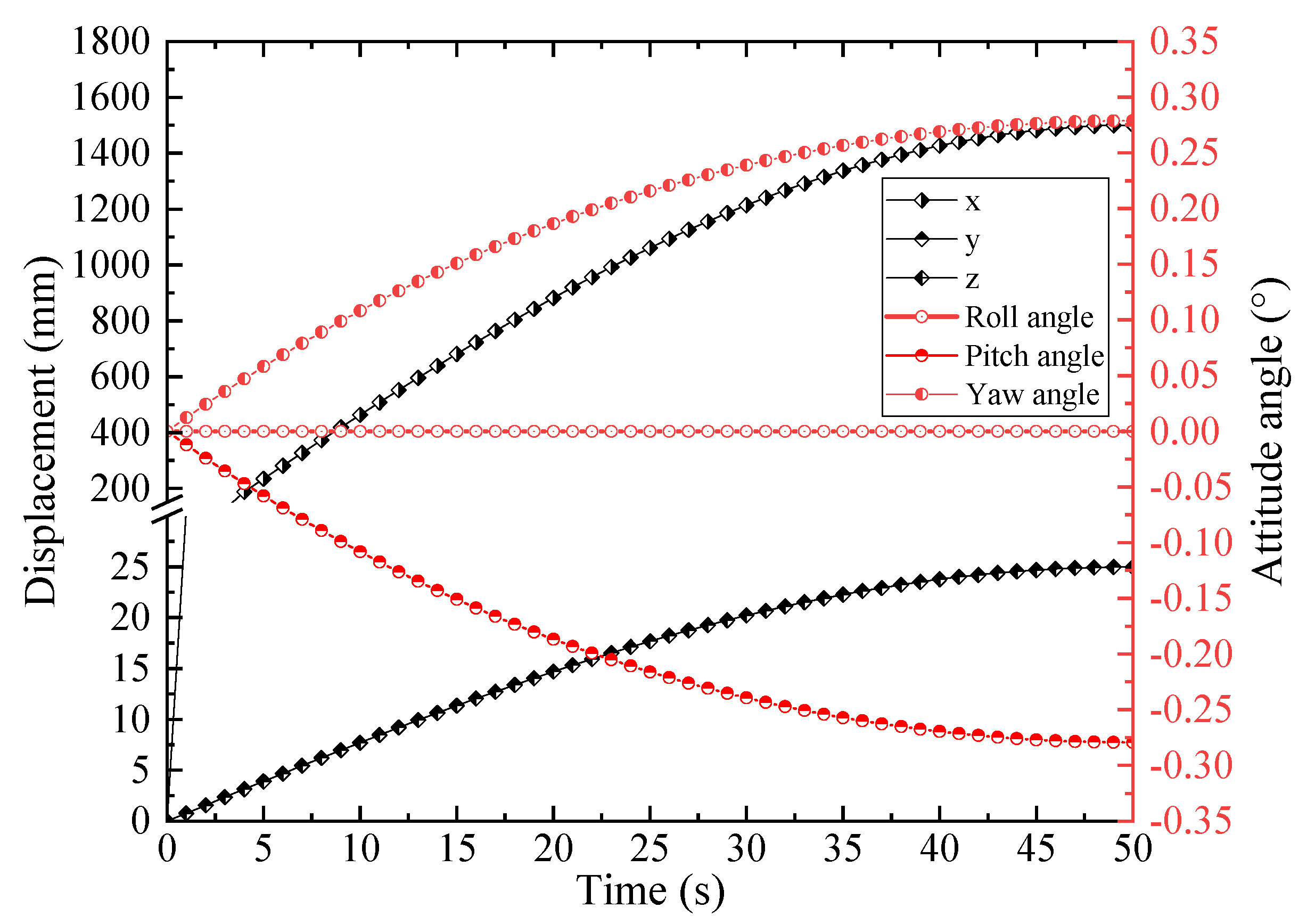
Figure 7.
Mean Displacements of thrust cylinders in different groups.
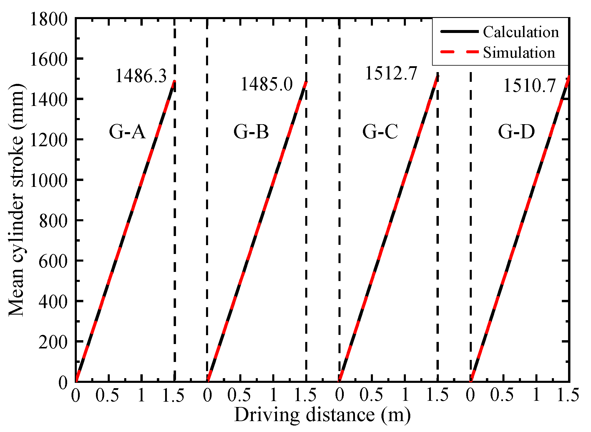
Figure 8.
Displacement distribution of thrust cylinders at 50 s (unit: mm).

Figure 9.
The attitude angles variation with the difference of mean cylinder strokes.
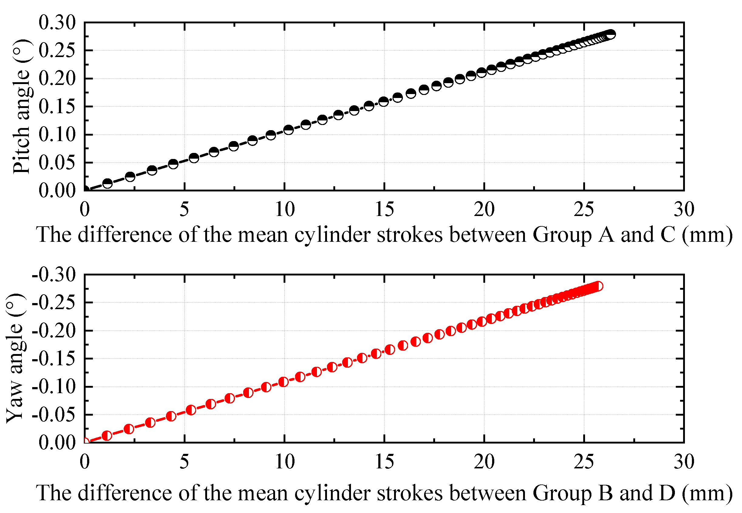
Figure 10.
Velocity–time diagram of different cylinders.
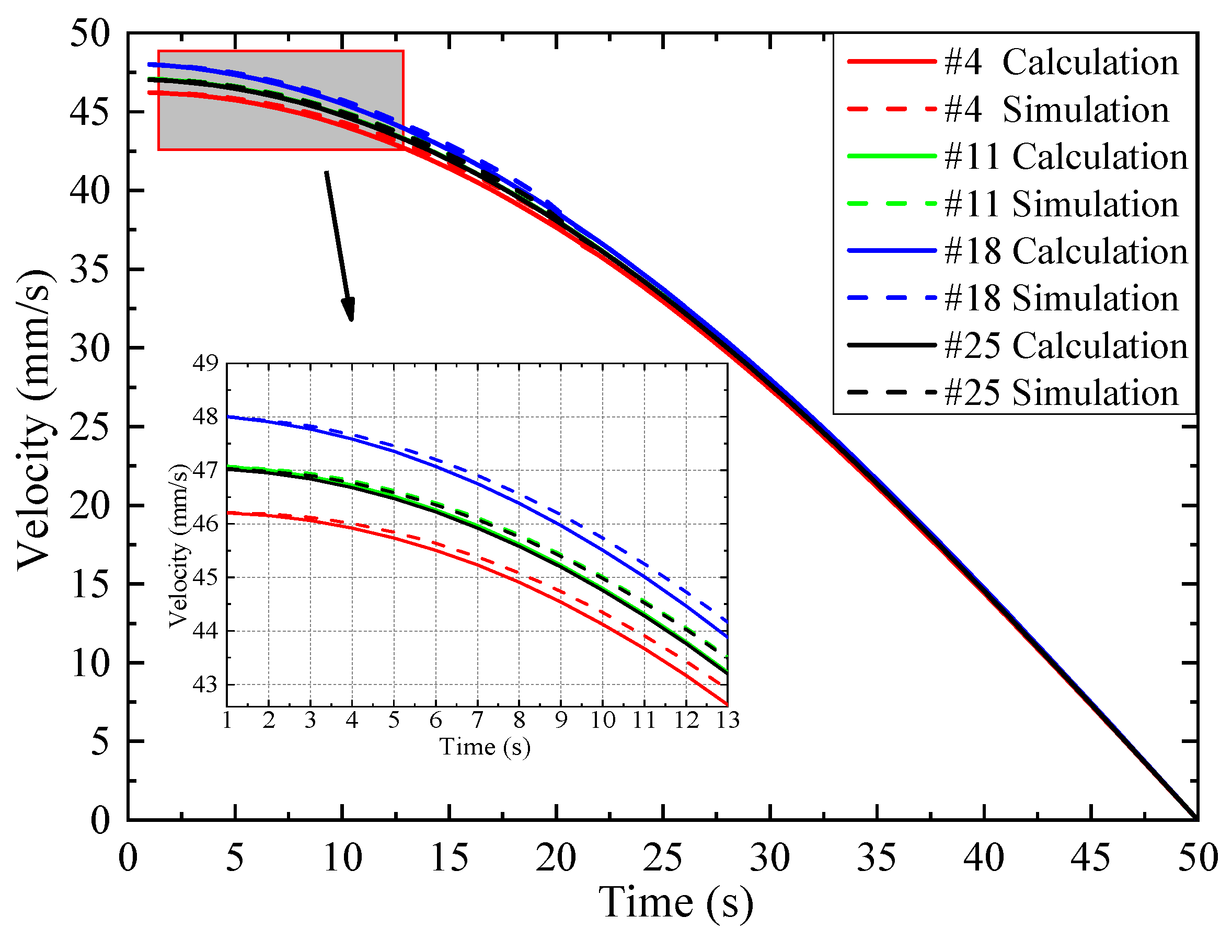
Figure 11.
Velocity distribution of thrust cylinders (unit: mm/s). (a) t = 10 s. (b) t = 30 s.

Figure 12.
Acceleration–time diagram of different cylinders.

Figure 13.
Acceleration distribution of thrust cylinders (unit: mm/s2). (a) t = 30 s. (b) t = 50 s.


Table 1.
The structure and dimension information of the model.
| No. | Model Parameters | Value |
|---|---|---|
| 1 | Outer diameter of shield (D) | 6560 mm |
| 2 | Thickness of shield shell (δ) | 60 mm |
| 3 | Radius of the distribution of the cylinders (R0) | 2990 mm |
| 4 | Length of shield body (Ltotal) | 8000 mm |
| 5 | Length of the front shield (LBC) | 1800 mm |
| 6 | Thrust cylinder specification | Φ220/180 × 2150 mm |
| 7 | Number of thrust cylinders (n) | 27 |
Publisher’s Note: MDPI stays neutral with regard to jurisdictional claims in published maps and institutional affiliations. |
© 2022 by the authors. Licensee MDPI, Basel, Switzerland. This article is an open access article distributed under the terms and conditions of the Creative Commons Attribution (CC BY) license (https://creativecommons.org/licenses/by/4.0/).
Share and Cite
MDPI and ACS Style
Wang, X.; Yuan, D.; Wang, X.; Wu, J. Kinematic Analysis and Virtual Prototype Simulation of the Thrust Mechanism for Shield Machine. Appl. Sci. 2022, 12, 1431. https://doi.org/10.3390/app12031431
AMA Style
Wang X, Yuan D, Wang X, Wu J. Kinematic Analysis and Virtual Prototype Simulation of the Thrust Mechanism for Shield Machine. Applied Sciences. 2022; 12(3):1431. https://doi.org/10.3390/app12031431
Chicago/Turabian StyleWang, Xuyang, Dajun Yuan, Xiaoyu Wang, and Jin Wu. 2022. "Kinematic Analysis and Virtual Prototype Simulation of the Thrust Mechanism for Shield Machine" Applied Sciences 12, no. 3: 1431. https://doi.org/10.3390/app12031431
Note that from the first issue of 2016, this journal uses article numbers instead of page numbers. See further details here.