Article

Experimental and Implementation of a 15 × 10 TEG Array of a Thermoelectric Power Generation System Using Two-Pass Flow of a Tap Water Pipeline Based on Renewable Energy

by
Mohammed A. Qasim
1,2,*,
Vladimir I. Velkin
1 and
Sergey E. Shcheklein
1
1
Nuclear Power Plants and Renewable Energy Sources Department, Ural Federal University, 620002 Yekaterinburg, Russia
2
Department of Projects and Engineering Services, Ministry of Health, Baghdad 10047, Iraq
*
Author to whom correspondence should be addressed.
Appl. Sci. 2022, 12(15), 7948; https://doi.org/10.3390/app12157948
Submission received: 12 July 2022 / Revised: 4 August 2022 / Accepted: 5 August 2022 / Published: 8 August 2022
(This article belongs to the Special Issue Renewable and Sustainable Energy Integration in Power Systems)

Abstract

:
At the present time, the entire world is suffering from global climate change due to emissions caused by the combustion of fossil fuels. Thus, it is necessary to look for alternative power sources to generate clean electrical energy. Thermoelectric generators (TEG) are one of these alternatives. They convert thermal energy into useful electricity. There are many thermal energy sources such as hot water pipes. The current paper aims to convert waste heat from solar water-fed hot water pipes into electricity using a TEG panel made from 15 × 10 TEG modules. A pipe through which hot water flows serves as the hot side of the panel. The cold side of the panel is cooled using normal tap water. The maximum recorded temperature difference is 42.35 °C which yields an open-circuit voltage of 15.3 V. The maximum efficiency of the panel is 2.1% with an average energy production of 1.435 kWh. This proposed novel TEG panel system can be used continuously day and night. This is in contrast to a solar system, which operates only during the day, as it relies solely on solar radiation.

1. Introduction

With the insatiable demand for energy to meet human consumption and industrial operations, traditional non-renewable energy resources have become increasingly depleted. The quest is very active for new, cleaner, and more environmentally friendly technologies with improved energy efficiency and renewable energy sources. As a result, energy efficiency is a paramount goal [1,2]. At the present time, the whole world suffers from global climate change driven by carbon emissions. Thus, it is necessary to develop and integrate new electrical energy sources based on renewable energy and dissipated energy sources such as waste heat [3]. Thermoelectric Generators (TEGs) are a good choice to dependably convert a temperature difference between two materials into electricity [4]. TEGs operate on the principle of the Seebeck effect. A temperature difference applied across a TEG module results in the generation of an electric current. This is due to the presence of two kinds of charge carriers in semiconductor materials [5]. In the last decade, TEGs have been a huge interest of many researchers to develop systems that can convert thermal energy into electricity. H. Su et al. [6] used commercially available TEG1-241-1.4-1.2 modules to convert the dissipated heat from a coal fire into electricity. The capacity of their design can generate 700 W at an 80 °C temperature differential. N. Nararom and P. Bamroongkhan [7] studied power generation from TEG modules by converting solar heat energy using a Fresnel lens. A good temperature difference of about 38.6 °C was achieved across the TEG module. The hot side received solar energy via a Fresnel lens and the cold side was cooled using a 12 V fan. Work was done by W. Jiang et al. [8] using asphalt pavement. Their work used the heat of pavement surfaces to produce useful electrical energy using three Road Thermoelectric Generator System (RTEGS) modules. This design reduced pavement slab temperature by 8–9 °C in the hot season, with an electrical output of 0.564 V from an asphalt slab with dimensions of 300 × 300 × 100 mm. G. Tan et al. [9] reviewed the materials that can be used to convert thermal energy into electrical energy. They studied the materials based on their operating temperature and the types that are most likely to be used in future devices. R. Goswami and R. Das [10] proposed a TEG that works on the dissipated heat from a biomass engine. The generated electrical energy from their TEGs was used to recharge the 12 V battery of a UPS. The maximum open circuit voltage was 31.52 V, whereas the maximum temperature difference was 40.12 °C. K. Xie et al. [11] proposed a new hydrothermal power generation device that uses a thermoelectric converter and a system for energy management. In their design, the temperature difference between the thermal generator and thermo-electrical generator was increased by 76.2%. S. Jena et al. [12] considered three kinds of micro-grid systems. One of them was a photovoltaic (PV) combined with a TEG. These systems were simulated using MATLAB SIMULINK. Y. Byon and J. Jeong [13] fabricated an energy harvesting block based on TEGs that was integrated with a phase change material and mounted on the outer side of a building wall. The role of phase change material was to cool the low-temperature side of the TEG module. The annual electricity production was about 2.1 kWh/m2. D. Luo et al. [14] proposed a comprehensive model to study the settings of a TEG and thermoelectric cooler at various boundary conditions. In their work, they investigated the effects of cross-sectional area, ceramic plates, the number of couples, and heat loss. P. Ying et al. [15] reported on the performance of TEG materials such as Bi2Te3, substitute composites, together with p-type MgAgSb and n-type Mg3(Sb,Bi)2, using a versatile, simple, and scalable processing routine. Their work focused on the scalability and feasibility of high-performance TEG modules based on sustainable components for improving low-grade heat recovery. B. Qin et al. [16] developed SnSe crystals with an extensive band gap with striking TEG properties via Pb alloying. In their research, they found that 31 TEG pairs had the capability to produce an acceptable power level.
The current research examines the production of electrical energy from parallel and series of TEG module connections. The current work aims to convert waste heat from solar water-fed hot water pipes into useable electricity that may be utilized to power low-energy electrical loads in residences throughout the day and night. The design involves constructing a TEG panel built from combinations of 150 TEG modules. The source of the heat is the wasted heat from the hot water tap pipes fitted on the hot side of the panel. On the cold side, normal tap water is used which is passed through several heat sinks. The current research is arranged as follows. An introduction is given first then followed by materials and methodology, measurement errors, results, and discussion. The paper finally offers conclusions of the study and recommendations for further work.

2. Materials and Methodology

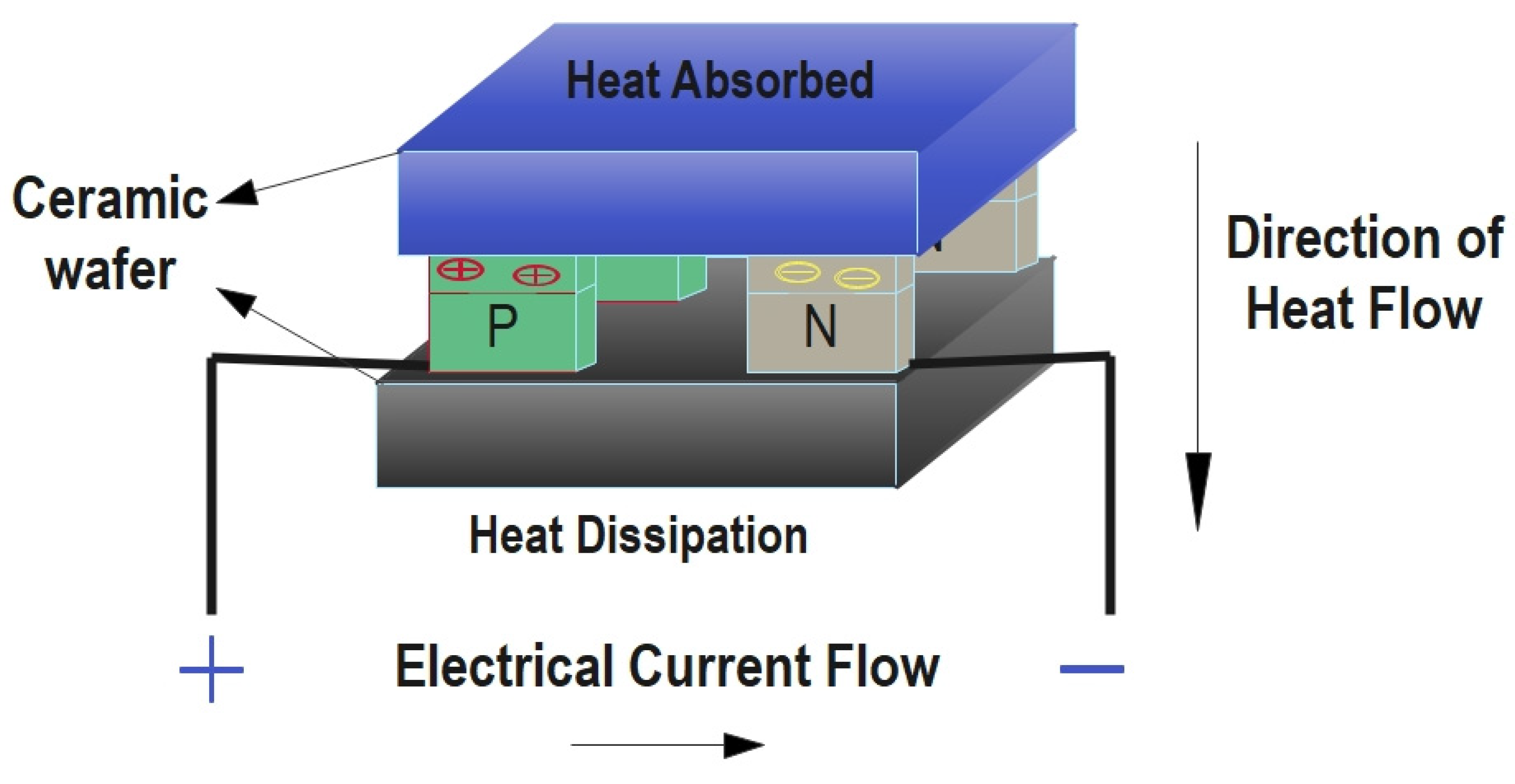
2.1. Principle and Mechanism of the TEG Module

A thermoelectric generator is a direct energy conversion device. TEGs have no moving components and do not have any intermediate modes of operation. They convert thermal or heat energy into electricity [17]. TEGs have two sides, one that is hot and the other that is cool. It is possible to achieve the Seebeck effect [18] in a thermoelectric material when a temperature differential is formed on opposite sides of the material. As a consequence, energy is transferred from a lower to a higher level and a voltage differential is developed. The voltage difference between the hot and cold sides of a TEG is proportional to the temperature difference between them. The current density that results from this is as follows:
J = σ ( Δ V + E e m f )
where E denotes the electric field, σ represents the conductivity of electricity, emf (electromotive force) in another meaning represents the Seebeck effect, and ΔV denotes a voltage difference. Heat dissipation or absorption processes at the junction of p- and n-type materials are described by the Peltier effect [19,20]. When the Peltier model absorbs heat, it generates electricity. When it dissipates heat, it consumes power.
TEGs are made up of components with large concentrations of positive charges in p-type junctions and high concentrations of negative charges in n-type junctions. A significant number of positive charges or holes are doped into a p-type material, resulting in a positive Seebeck coefficient [21]. A negative Seebeck coefficient is obtained when an n-type material is doped with a large concentration of negative charges or electrons. Figure 1 shows a schematic of a TEG module.
Q h   represents the rate of heat absorption and Q c is the heat dissipation at the hot and cold junctions of a TEG module, respectively, which is calculated as follows [18,22]:
Q h = ( K p + K n ) ( T h T c ) + ( α p α n )   I T h I 2 R 2
Q c = ( K p + K n ) ( T h T c ) + ( α p α n )   I T c + I 2 R 2
The thermal conductivities of the p-type and n-type TEG legs, respectively, are denoted by K p and K n . The hot and cold junction temperatures are denoted by T h and T c , respectively, while the Seebeck coefficients of the p-type and n-type TEG legs are α p and α n , respectively.
The electrical power of a TEG, as shown in Figure 1, is simply the voltage across the external load and the current in the circuit, calculated using a power balancing formula. Output power can be obtained in the following way:
W = Q h Q c = V . I
Rearranging and simplifying Equations (2)–(4) yields the following results:
V = ( α p α n ) ( T h T c ) I R
When Equation (5) is simplified and the assumptions that Δ T = ( T h T c ) and α = ( α p α n ) are made, the following result is obtained:
V = α × Δ T I R
If there is an electric current flowing, the output voltage is shown in Equation (6). It is possible to compute the open circuit voltage [23] as:
Voc = α × Δ T
Δ T = T h T c
The Seebeck coefficient is represented by α and Voc is the open circuit voltage of a TEG module. Increasing the voltage can be accomplished by connecting numerous TEG modules in series or parallel [24]. Bismuth telluride was employed to make the TEG modules used in this study. The TEG module parameters in [17,25] were used in the current study.
A TEG panel was created by connecting TEG modules in series and parallel. This study’s goal is to transform waste heat from hot water pipes through which solar-heated water flows into useful power, as shown in Figure 2. An electric voltage can be obtained to charge a battery using a TEG panel when a temperature differential is applied to its surfaces. An inverter can convert the battery’s DC voltage into AC to power low-power devices such as CCTV recording devices or internet routers in homes. During the night, the TEG can supply electricity, since the water is usually stored in tanks for the purpose of using it in the evening. Certainly, this will lower household electricity bills.

2.2. Experimental Setup of a 15 × 10 TEG Panel

As illustrated in Figure 3, the series connections of 10 TEG modules are linked in parallel to produce 15 lines of TEG modules. Experimental work was done on a July day in Iraq. The aim of the proposed system is to generate and maximize output power from the thermoelectric modules (TEGs).
The processing system consists of three Sections. Section 1 represents the hot surface of the system, where 30 pieces of an aluminum heating block are used. The dimensions of each piece are (40 × 240 × 10 mm) [26], with an identical cooling block on the opposite side of the panel. This was built as shown in Figure 4. Then the hot water coming from a solar water heater passes these pieces in parallel flow, with a constant velocity (0.8 m/s), to ensure a constant flow rate of water evenly entering the heating block, as shown in Figure 5. Then, this water goes into the house for domestic purposes after it heats the upper surface of the panel.
Section 2 represents the cold surface of the TEG panel, which is at the bottom of the panel. Here, the technology is the same as for the upper surface, which is an aluminum water-cooling block. However, here, normal tap water enters the cooling block, at a temperature that ranges from 25 to 34 °C. The flow of this water will dissipate the heat coming from the hot surface of the plate to the outside of the system. Then, this water is returned to the solar water heater. Here, an important new idea of this work emerges. This is to heat the water in two stages. The first stage is when it passes through a (TEG panel). The second time is in a solar water heater.
Section 3 represents the many TEG modules, as shown in Figure 6. They are connected electrically in series and parallel to obtain the required voltage. Thermal paste is used to improve thermal contact between the module components and allow for a uniform temperature distribution at each side of the TEG module, as shown in Figure 7. Additionally, insulators are here between the wires and the electrical connections passing between the TEG pieces to ensure that no electrical short-circuit occurs.
Then, acrylic plates are installed on the two surfaces of the panel in a sandwich configuration so that all the connecting parts are installed correctly and evenly.
The significant difference between this system and solar panels is that the former can be used continuously during the day and night hours. This is unlike solar systems that operate during daylight hours because they depend only on solar radiation.

2.3. Electrical Connections and Data Measurements

In practice, many measuring devices were used during the experiment (digital clamp meter, a single-end glass seal (NTC) thermistor temperature sensor, digital temperature humidity meter) integrated with a microcontroller to obtain more accurate results. Heat sensors (thermocouples) are attached at various places on the panel to determine the temperature distribution on the test panel. All of the mentioned sensors here are sending their measurement signals to an Arduino Mega which is shown in Figure 8.
The recorded data is shown by Arduino IDE serial monitor and saved into a text file. To optimize the TEG panel output voltage, two approaches are used in this study. A microcontroller (Mega) was used to measure the current and voltage in real-time in conjunction with some manual measurements.

2.4. Data Reduction

The temperatures on the hot and cold sides have an impact on a TEG module’s maximum efficiency. This is because the temperature of a module affects the voltage and current it produces. According to Equation (9) [27,28,29], the maximum efficiency of a TEG module can be anticipated as:
η m a x   = T h   T C   T h   1 + Z T ¯ 1   1 + Z T ¯ + T c T h
T ¯ = T h   + T c 2 is the mean temperature of the source, while T h   and T c   are the temperatures of the hot and cold sides of TEG, respectively. A figure of merit is denoted by the symbol Z T ¯ , where Z T ¯ , and Z p , n are defined as [27,30]:
Z T ¯ p , n = α 2   T ¯ ρ   k
Z p , n = α 2     σ λ
The Seebeck coefficient, electrical conductivity and thermal conductivity are represented as α   , σ , and λ , respectively, in the above equation. All of these parameters depend on the material chosen to fabricate the TEG, which in this case is Bi2Te3. Z T ¯ is a constant in the above equation. Nevertheless, Z T ¯ has a temperature dependency, as shown by Equation (9). In consideration of the fact that Z T ¯ is dependent upon the characteristics of fabricated materials, the value of Z T ¯ was determined considering the temperatures at which the experiments were carried out. The normalized temperature ranges between (0 and 1). As suggested by [31].

3. Measurement Errors: An Investigation

The effects of measurement errors on experimental results are briefly described in this section. These include the measurement equipment rate of error, as well as those of the sensors and microcontrollers (Arduino). A range of parameters was assessed to estimate the uncertainties associated with the instruments employed for the various measurements. Results for the digital clamp meter and the NTC sensor are shown in Table 1. The standard uncertainty u n [32,33] can be calculated using Equation (12).
u n       = a n       3
The accuracy of an instrument, according to its manufacturer’s specifications, is signified by the symbol a n . When Z is dependent on a number of different inputs, the uncertainty of Z can be evaluated using Equation (13) [32].
u ( z ) = [ ( δ z δ y 1 ) 2   u 2 ( w 1 ) + ( δ z δ y 2 ) 2   u 2 ( w 2 ) +     + ( δ z δ y n ) 2   u 2 ( w n ) ] 1 2
Potential errors are denoted by the symbols y 1 ,   Δ y 2   ,     Δ y n [34,35,36]. It was discovered that the total percentage of uncertainty in the designed TEG system which is employed in this experiment is 1.86%. A system such as the one employed in our tests can tolerate this level of variability.
Table 1. The accuracy and uncertainty of various instruments.
Measuring InstrumentRangeAccuracyUncertainty %
AC/DC Digital Clamp Meter, V−20~70 °C±0.01%0.01
Digital and Temperature Humidity Meter, °C, RH%−20~70 °C±1.0 °C%0.58
0~100% RH±3.0% RH1.73
NTC sensor−200~260±1%0.58

4. Results and Discussion

4.1. Effect of Solar Water and Normal Tap Water on the Temperature Difference across a 15 × 10 TEG Panel

A TEG module relies on the temperature difference between its surfaces to generate electric power using the Seebeck effect. In the proposed system, two methods are used to provide this temperature difference, depending on the renewable energy source. The first method, directs the passage of normal tap water through the TEG panel, as this water performs the task of dissipating heat on the surface of the cold panel. This is usually at a temperature ranging from 25 to 34 °C. The other way is by flowing this same water after it leaves the panel to the solar water heater, and then the water is used to heat the hot surface of the TEG. After that, the water is used for domestic purposes. In this way, a temperature differential is formed, and thus electrical energy can be generated by the panel. The proposed TEG panel was tested experimentally on a July day in Iraq. The hot ( T h ) and cold side temperatures ( T c ) are given in Figure 9.
In this figure, it can be observed that ( T c ) is low at the start of the experiment. Then, it increased because ( T h ) has an effect on ( T c ) over time until an equilibrium condition is established. The Δ T between both the hot and cold sides of the 10 × 15 TEG Panel is reduced as a result of this impact. On the hot side, the TEG panel measured low and high temperatures of 67.22 °C and 67.88 °C, respectively. Despite this, the temperature averaged 67.62 °C. Low and high temperatures of 25.40 °C and 33.28 °C were, respectively, recorded on the cold side, with an average temperature of 29.95 °C. On the surface of the panel, microcontroller thermocouples detected a temperature differential of 37.67 °C. During the same time period, the largest and lowest temperature variations were 42.35 °C and 34.22 °C, respectively. These results were acquired employing thermocouples in direct contact with panel surfaces, which allowed for more exact results.

4.2. Electrical Performance of the Proposed Panel

Figure 10 depicts the experimentally measured electric voltages. With a decrease in ΔT, the voltage fell dramatically. The average voltage for the 15 × 10 TEG panel was 13.73 V, with the greatest and lowest voltages of 15.3 V and 12.51 V, respectively.
The illustration in Figure 11 shows that the power output of the 15 × 10 TEG panel ranged from 19.72 W to 29.49 W during the experiments, with an average power output of 23.92 W, where the resistance of the used load is 5 Ω. The panel experienced varying temperatures during the studies and as a result, it demonstrated enhanced power with higher temperature differentials.
The greatest temperature difference (ΔT) across the panel was 42.35 °C. However, when ΔT decreased, the output power of the panel also decreased.

4.3. TEG’s Maximum Electrical Efficiency in Relation to Thermoelectric Materials

The value of the figure of merit ( Z T ¯ ) of the semiconductor behavior of a TEG module depends on the type of materials used. Bismuth telluride Bi2Te3 was used in the current study. From Equation (9), the maximum efficiency ηmax of the system can be calculated.
Figure 12 depicts that the average maximum efficiency achieved by the TEG panels was 1.77%. The lowest and highest values obtained during the experiments were 1.601% and 2.1%, respectively. The increase in this proposed mechanism is significant. This efficiency is considered important because the system operates under a low temperature difference compared to other systems, such as car exhaust and chimneys, among others. These conditions have twice the temperature difference used in the current work.
In Figure 12, the relation between ΔT and ηmax seems linear. The estimated regression equation for the data of this figure is:
η m a x   = 0.089 + 0.049   Δ T
where the value of the correlation between ΔT and ηmax is 0.9998 i.e., positively high correlated.
A significant improvement in efficiency and output power is observed. This occurs since this proposed system uses heat sources that depend on available water rather than relying on other variables and unstable heat sources. As such, this system is independent, cost-effective, and does not use complex mechanisms.
Table 2 represents a comparison of the research discussed above in this paper as well as others with the results of the current work. The results are either better than or competitive with systems presented in earlier studies. Most often, the proposed system gives better results, especially if utilization time is extended for many hours. The duration of each experimental run was only a few minutes, but if it lasted for many hours then the energy production would have been 1.435 kWh.

5. Conclusions and Recommendations for Further Work

This paper examines a renewable energy source and presents a new design for a TEG panel, which is formed as a connection parallel and series of many TEG modules. In the current work, the conclusions are summarized as follows.
  • It is crucial in our designed TEG system to work at low-temperature differences which are considered to be given to using appropriate multi-layers of TEG modules to harvest more energy to yield greater output power with increased efficiency. The results of this design are very important for applications that are related to heat recovery. The significant difference between this system and PV solar panels is that this system can be used continuously during the day and night hours. Unlike solar systems that only operate during daylight hours because they depend on solar radiation, our system can function at night. The TEG panel can supply electricity since hot water is usually stored in tanks for the purpose of using it in the evening. Certainly, this will lower household electricity bills. From the experimental results:
  • An important new idea emerges from this work. This is to heat water in two stages. The first time is when it passes through the cold side of a TEG panel, and the second time is in the solar water heater.
  • On a sunny day, solar radiation is abundant. This leads to an increased temperature of water in the solar water heater, and the TEG panel achieves its maximum ΔT. This will lead to maximizing the terminal voltage for the TEG panel. The heat exchangers for both sides of the panel are made of aluminum. This creates a non-uniform dissipation of heat at the hot and cold sides of the TEG panel. Thus, the development of power is more efficient.
  • During the experiment, the highest recorded efficiency for the system was 2.1%. The average voltage at the terminals of the TEG panel is 13.73 V, where the greatest and lowest voltages of 15.3 V and 12.51 V. The average power output was (23.92 W). These values may increase if more effective cooling is used.
  • The created system is an economical and eco-friendly type of renewable energy converter that can be used in hot places or even combined with other types of renewable energy sources to maximize the amount of power produced from clean and renewable sources overall.
  • The findings of this investigation demonstrate that the suggested system is superior to or on par with systems described in other published studies.
The integration with other renewable energy sources such as photovoltaic panels to build a PV-TEG system will be considered in the future. A complete system will be researched to verify that the system harvests clean electrical energy.

Author Contributions

Conceptualization, M.A.Q. and V.I.V.; methodology, M.A.Q.; software, M.A.Q.; validation, M.A.Q., S.E.S. and V.I.V.; formal analysis, M.A.Q. and V.I.V.; investigation, M.A.Q.; resources, S.E.S. and M.A.Q.; data curation, M.A.Q. and S.E.S.; writing—original draft preparation, M.A.Q.; writing—review and editing, M.A.Q.; visualization, M.A.Q., supervision, V.I.V.; project administration, M.A.Q.; funding acquisition, M.A.Q. All authors have read and agreed to the published version of the manuscript.

Funding

This research received no external funding.

Institutional Review Board Statement

Not applicable.

Informed Consent Statement

Not applicable.

Data Availability Statement

All important data is included in the manuscript.

Conflicts of Interest

The authors declare no conflict of interest.

Nomenclature

SymbolsDescriptionSymbolsDescription
E Electric field [ V / m ] u ( z ) Function number of different inputs
I Electric current [ A ] V Voltage [ V ]
J Current density [ A   m 2 ]VocOpen circuit voltage [ V ]
k Thermal conductivity [ W / m   K ] Z p , n Figure of merit of p-type and n-type junctions [ 1 / K ]
K n n-type Thermal conductivity [ W   m 1 K 1 ] Z T ¯ Figure of merit, Dimensionless [unit Less]
K p p-type Thermal conductivity [ W   m 1 K 1 ] α Seebeck coefficient [ V   K 1 ]
Q c Dissipated heat of TEG [ W ] α n Seebeck coefficient of n-type thermoelements [ V   K 1 ]
Q h Absorbed heat of TEG [ W ] α p Seebeck coefficient of p-type thermoelements [ V   K 1 ]
R Electrical resistance [ ] Δ T Temperature difference [ K ]
T ¯ Mean temperature Δ V voltage difference [ V ]
T c Cold side temperature [ K ] λ Thermal conductivity [ W / m   K ]
T E G Thermoelectric generator σ Electrical conductivity [ 1   m 1 ]
T h Hot side temperature [ K ] η m a x   Maximum efficiency [ % ]
u n Standard uncertainty y 1 ,   Δ y 2 Potential errors

References

  1. Zhang, Q.; Huang, X.Y.; Bai, S.Q.; Shi, X.; Uher, C.; Chen, L. Thermoelectric Devices for Power Generation: Recent Progress and Future Challenges. Adv. Eng. Mater. 2015, 18, 194–213. [Google Scholar] [CrossRef]
  2. Fang, L.; Dong, H.; Ding, K.; Wang, N. Peak shaving strategy of power grid with concentrating solar power plant. In Proceedings of the 2017 13th IEEE Conference on Automation Science and Engineering (CASE), Xi’an, China, 20–23 August 2017; pp. 1633–1638. [Google Scholar] [CrossRef]
  3. Qasim, M.A.; Velkin, V.I.; Shcheklein, S.E. Development of a Computational Fluid Dynamics (CFD) Numerical Approach of Thermoelectric Module for Power Generation. Crystals 2022, 12, 828. [Google Scholar] [CrossRef]
  4. Petsagkourakis, I.; Tybrandt, K.; Crispin, X.; Ohkubo, I.; Satoh, N.; Mori, T. Thermoelectric materials and applications for energy harvesting power generation. Sci. Technol. Adv. Mater. 2018, 19, 836–862. [Google Scholar] [CrossRef] [PubMed]
  5. Qasim, M.A.; Velkin, V.I.; Hassan, A.K. Seebeck Generators and Their Performance in Generating Electricity. J. Oper. Autom. Power Eng. 2022, 10, 200–205. [Google Scholar] [CrossRef]
  6. Su, H.; Zhou, F.; Qi, H.; Li, J. Design for thermoelectric power generation using subsurface coal fires. Energy 2017, 140, 929–940. [Google Scholar] [CrossRef]
  7. Nararom, M.; Bamroongkhan, P. A Study on Thermoelectric Power Generator by Solar Energy Using Fresnel Lens. In Proceedings of the 2018 International Electrical Engineering Congress (iEECON), Krabi, Thailand, 7–9 March 2018; pp. 1–4. [Google Scholar] [CrossRef]
  8. Jiang, W.; Xiao, J.; Yuan, D.; Lu, H.; Xu, S.; Huang, Y. Design and experiment of thermoelectric asphalt pavements with power-generation and temperature-reduction functions. Energy Build. 2018, 169, 39–47. [Google Scholar] [CrossRef]
  9. Tan, G.; Ohta, M.; Kanatzidis, M.G. Thermoelectric power generation from new materials to devices. Philos. Trans. 2018, 377, 20180450. [Google Scholar] [CrossRef] [Green Version]
  10. Goswami, R.; Das, R. Waste heat recovery from a biomass heat engine for thermoelectric power generation using two-phase thermosyphons. Renew. Energy 2019, 148, 1280–1291. [Google Scholar] [CrossRef]
  11. Xie, K.; Wu, S.; Yang, C.; Ruan, Y.; Hong, Y. A New Seafloor Hydrothermal Power Generation Device Based on Waterproof Thermoelectric Modules. IEEE Access 2020, 8, 70762–70772. [Google Scholar] [CrossRef]
  12. Jena, S.; Mohapatra, B.; Kar, S.K.; Sahu, B.K. Analysing the Essentiality of Energy Storing Device in Integration and Non-integration of Thermoelectric Generator in Microgrid. In Proceedings of the 2020 International Conference on Computational Intelligence for Smart Power System and Sustainable Energy (CISPSSE), Keonjhar, India, 29–31 July 2020; pp. 1–6. [Google Scholar] [CrossRef]
  13. Byon, Y.-S.; Jeong, J.-W. Annual energy harvesting performance of a phase change material-integrated thermoelectric power generation block in building walls. Energy Build. 2020, 228, 110470. [Google Scholar] [CrossRef]
  14. Luo, D.; Wang, R.; Yu, W.; Zhou, W. Parametric study of a thermoelectric module used for both power generation and cooling. Renew. Energy 2020, 154, 542–552. [Google Scholar] [CrossRef]
  15. Ying, P.; He, R.; Mao, J.; Zhang, Q.; Reith, H.; Sui, J.; Ren, Z.; Nielsch, K.; Schierning, G. Towards tellurium-free thermoelectric modules for power generation from low-grade heat. Nat. Commun. 2021, 12, 1–6. [Google Scholar] [CrossRef] [PubMed]
  16. Qin, B.; Wang, D.; Liu, X.; Qin, Y.; Dong, J.-F.; Luo, J.; Li, J.-W.; Liu, W.; Tan, G.; Tang, X.; et al. Power generation and thermoelectric cooling enabled by momentum and energy multiband alignments. Science 2021, 373, 556–561. [Google Scholar] [CrossRef] [PubMed]
  17. Nagaraj, N.; Nandan, A.M.; Kumar, L.S. Electrical Energy Harvesting Using Thermo Electric Generator for Rural Communities in India. Int. J. Energy Power Eng. 2019, 13, 663–667. [Google Scholar]
  18. Hsu, C.-T.; Huang, G.-Y.; Chu, H.-S.; Yu, B.; Yao, D.-J. An effective Seebeck coefficient obtained by experimental results of a thermoelectric generator module. Appl. Energy 2011, 88, 5173–5179. [Google Scholar] [CrossRef]
  19. Patil, R.P.; Suryawanshi, P.; Pawar, A. Thermoelectric refrigeration using Peltier effect. Int. J. Eng. Sci. Res. Technol. 2017, 6, 614–618. [Google Scholar]
  20. Nikam, A.N.; Hole, J.A. A Review on use of Peltier Effects. Int. J. Sci. Spiritual. Bus. Technol. 2014, 2, 2277–7261. [Google Scholar]
  21. Chen, J.; Li, K.; Liu, C.; Li, M.; Lv, Y.; Jia, L.; Jiang, S. Enhanced Efficiency of Thermoelectric Generator by Optimizing Mechanical and Electrical Structures. Energies 2017, 10, 1329. [Google Scholar] [CrossRef] [Green Version]
  22. Ge, M.; Li, Z.; Zhao, Y.; Xuan, Z.; Li, Y.; Zhao, Y. Experimental study of thermoelectric generator with different numbers of modules for waste heat recovery. Applied Energy 2022, 322, 119523. [Google Scholar] [CrossRef]
  23. Qasim, M.A.; Alwan, N.T.; PraveenKumar, S.; Velkin, V.I.; Agyekum, E.B. A New Maximum Power Point Tracking Technique for Thermoelectric Generator Modules. Inventions 2021, 6, 88. [Google Scholar] [CrossRef]
  24. Champier, D. Thermoelectric generators: A review of applications. Energy Convers. Manag. 2017, 140, 167–181. [Google Scholar] [CrossRef]
  25. Thermoelectric Power Generator TEG Peltier (SP1848-27145). Available online: https://www.autobotic.com.my/Thermoelectric-Power-Generator-TEG-Peltier-SP1848-27145 (accessed on 28 July 2022).
  26. Clyxgs Aluminum Water Cooling Block. Available online: https://www.newegg.com/p/2YM-0045-00255 (accessed on 29 July 2022).
  27. Gaurav, K.; Pandey, S.K. Efficiency calculation of thermoelectric generator by extracting waste heat, for practical applications. J. Renew. Sustain. Energy 2017, 7, 1–4. [Google Scholar]
  28. Yan, Z.; Song, K.; Xu, L.; Tan, X.; Hu, H.; Sun, P.; Liu, G.; Pan, C.; Jiang, J. Effects of interfacial properties on conversion efficiency of Bi2Te3-based segmented thermoelectric devices. Appl. Phys. Lett. 2021, 119, 233902. [Google Scholar] [CrossRef]
  29. Qian, D.; Ye, Z.; Pan, L.; Zuo, Z.; Yang, D.; Yan, Y. The mechanical and thermoelectric properties of Bi2Te3-based alloy prepared by constrained hot compression technique. Metals 2021, 11, 1060. [Google Scholar] [CrossRef]
  30. Memon, S.; Tahir, K.N. Experimental and Analytical Simulation Analyses on the Electrical Performance of Thermoelectric Generator Modules for Direct and Concentrated Quartz-Halogen Heat Harvesting. Energies 2018, 11, 3315. [Google Scholar] [CrossRef] [Green Version]
  31. Tritt, T.M.; Subramanian, M.A. Thermoelectric materials, phenomena, and applications: A bird’s eye view. MRS Bull. 2006, 31, 188–198. [Google Scholar] [CrossRef] [Green Version]
  32. Hendricks, T.J.; Yee, S.; LeBlanc, S. Cost Scaling of a Real-World Exhaust Waste Heat Recovery Thermoelectric Generator: A Deeper Dive. J. Electron. Mater. 2015, 45, 1751–1761. [Google Scholar] [CrossRef]
  33. Lv, S.; He, W.; Jiang, Q.; Hu, Z.; Liu, X.; Chen, H.; Liu, M. Study of different heat exchange technologies influence on the performance of thermoelectric generators. Energy Convers. Manag. 2018, 156, 167–177. [Google Scholar] [CrossRef]
  34. Kline, S.J.; McClintock, F.A. Describing Uncertainties in Single-Sample Experiments. Mech. Eng. 1953, 75, 3–8. [Google Scholar]
  35. Moffat, R.J. Describing the uncertainties in experimental results. Exp. Therm. Fluid Sci. 1988, 1, 3–17. [Google Scholar] [CrossRef] [Green Version]
  36. Qasim, M.A.; Velkin, V.I.; Shcheklein, S.E. The Experimental Investigation of a New Panel Design for Thermoelectric Power Generation to Maximize Output Power Using Solar Radiation. Energies 2022, 15, 3124. [Google Scholar] [CrossRef]
  37. Gou, X.; Xiao, H.; Yang, S. Modeling, experimental study and optimization on low-temperature waste heat thermoelectric generator system. Appl. Energy 2010, 87, 3131–3136. [Google Scholar] [CrossRef]
  38. Kadohiro, Y.; Cheng, S.; Cross, J.S. All-Day Energy Harvesting Power System Utilizing a Thermoelectric Generator with Water-Based Heat Storage. Sustainability 2020, 12, 3659. [Google Scholar] [CrossRef]
  39. Zhao, Y.; Wang, S.; Ge, M.; Li, Y.; Yang, Y. Energy and exergy analysis of thermoelectric generator system with humidified flue gas. Energy Convers. Manag. 2018, 156, 140–149. [Google Scholar] [CrossRef]
  40. Gou, X.; Yang, S.; Xiao, H.; Ou, Q. A dynamic model for thermoelectric generator applied in waste heat recovery. Energy 2013, 52, 201–209. [Google Scholar] [CrossRef]
Figure 1. Schematic depiction of a TEG module.
Applsci 12 07948 g001
Figure 2. A sustainable energy system using TEG panels and solar water heaters.
Applsci 12 07948 g002
Figure 3. (a) Single line of layer panel, and (b) Schematic diagram of a 15 × 10 TEG panel.
Applsci 12 07948 g003
Figure 4. (a) Schematic diagram of CLYXGS aluminum water block, and (b) individual pieces comprising an aluminum water block in the as-built system.
Applsci 12 07948 g004
Figure 5. Pipes and integration of the system.
Applsci 12 07948 g005
Figure 6. (a) Schematic diagram, and (b) image of single TEG module implementation.
Applsci 12 07948 g006
Figure 7. Thermal paste, arrays and insulators used in the panel.
Applsci 12 07948 g007
Figure 8. (a) Electrical connections of the panel board in parallel and series, and (b) Electrical connections of a microcontroller (Mega).
Applsci 12 07948 g008
Figure 9. ΔT, T h , and T c of a 15 × 10 TEG Panel.
Applsci 12 07948 g009
Figure 10. Voltage for 15 × 10 TEG panel systems.
Applsci 12 07948 g010
Figure 11. Power for 15 × 10 TEG panel at load of (50 W/5 Ω).
Applsci 12 07948 g011
Figure 12. Efficiency of a 15 × 10 TEG panel system.
Applsci 12 07948 g012
Table 2. Comparative analysis with earlier research.
ReferencesNo. of TEG ModulesMaximum Output PowerMaximum of ΔTMaximum EfficiencySource of Heat
[7]11.03 W38.6 °C1.81%Solar radiation focused by a Fresnel lens
[10]481.033 W39 °C2.218%Waste heat of a biomass engine
[11]185.6 W110 °CNot specifiedHydrothermal power generation
[13]40.03 W32 °CNot specifiedWalls of a building
[14] 13.13 W133 °C1.2%Not specified
[37]100.85 W58 °C2%Hot water
[38]Not specified21.17 W40 °C0.68%Heat Storage
[39]Not specified 24.4 W100 °C0.87 %Humidified flue gas
[40]186.5 W61.5 °C0.55%Hot water
Proposed15029.49 W42.35 °C2.1%Hot water pipelines
Publisher’s Note: MDPI stays neutral with regard to jurisdictional claims in published maps and institutional affiliations.

