
Autonomous Balloon Controls for Protection against Projectiles with Known Destinations


Electronic and Electrical Convergence Department, Hongik University, Sejong-ro, Jochiwon-eup, Sejong 2639, Korea
Appl. Sci. 2021, 11(9), 4077; https://doi.org/10.3390/app11094077
Submission received: 22 March 2021
/
Revised: 26 April 2021
/
Accepted: 28 April 2021
/
Published: 29 April 2021
(This article belongs to the Special Issue Advances in Robot Path Planning)
Abstract
:This article tackles autonomous balloon controls for protection against projectiles with known destinations. We introduce a defense strategy against an enemy projectile trying to reach a destination, such as a military base, which is known a priori. We further assume that the position of the platform that launches the projectile is known in advance. Because both the platform and the projectile’s destination are known in advance, we can predict the trajectory of the projectile before the projectile is launched. The proposed defense strategy is to deploy multiple balloons on the projectile’s feasible paths so that they block the incoming projectile effectively. Each balloon has GPS sensors for locating itself and IR sensors to detect an incoming projectile. Once the projectile is sufficiently close to a balloon, the balloon explodes to destroy the projectile. Since the projectile’s purpose is reaching its destination, the balloons can effectively intercept the projectile using this blocking strategy. As far as we know, this article is novel in utilizing multiple balloons for protection against an enemy projectile. The effectiveness of our defense strategy is further verified utilizing MATLAB simulations.
1. Introduction
Consider the problem of protection against projectiles with known destinations. We introduce a defense strategy against an enemy projectile (EP) trying to reach its destination, such as a military base, which is known a priori. We further assume that the location of the platform that launches the EP is known a priori. Since both the platform and the EP’s destination are known a priori, we can predict the trajectory of the EP before the EP is launched.
The proposed defense strategy is to deploy multiple balloons on the EP’s viable trajectories so that they block the incoming EP effectively. Each balloon has GPS sensors for locating itself and IR sensors to detect an incoming projectile. Once the EP is sufficiently close to a balloon, the balloon explodes to destroy the EP. Since the EP’s purpose is reaching its destination, the balloons can effectively intercept the EP utilizing this blocking strategy.
In the past, a fast interceptor has been widely used to destroy a fast-moving EP [1]. However, an interceptor needs to be controlled precisely, in order to hit a fast-moving EP. For this interception, the target’s real-time position must be measured precisely using expensive radar systems. Moreover, an interceptor must move faster than a fast-moving EP, in order to capture the EP. Thus, an interceptor is much more expensive than an EP. Since an interceptor is destroyed after the engagement, we argue that this traditional interceptor system is not suitable for protection against cheap EPs.
Since balloons move much slower than an EP, we can consider a balloon as a static interceptor capturing an EP. In other words, an EP can be considered as a target, and our goal is to destroy the target utilizing a static interceptor (balloon).
The proposed defense strategy is useful when many cheap EPs are launched towards their destination simultaneously. We can deploy balloons considering the position of each EP, and the balloons can block the path of each EP effectively. The balloons provide cheap and effective defense systems against the attack of cheap EPs.
The References [2,3,4] utilized motion camouflage to develop the motion control of an interceptor. Here, we say that the interceptor is in the motion camouflage state if the interceptor approaches a target while appearing stationary at a focal point. References [5,6] addressed a 2D motion camouflage control with respect to a static focal point. In [6], a neural network architecture was utilized to achieve simulated motion camouflage.
Proportional Navigation Guidance (PNG) laws were widely utilized to let an interceptor capture a target [1,7]. PNG laws were addressed considering an interceptor, which can measure the bearing of the target utilizing on-board sensors. Command guidance is a control, such that a base station relays signals to a guided interceptor via radio control. The principle of command to line-of-sight (CLOS) guidance [8,9] is to make the interceptor fly as near as possible along the LOS line.
With the advancement of anti-missile technology, cooperative multi-missile attack and defense is attracting increasing attention. The authors of [10] proposed a guidance law with controllable attack time and angle-of-attack constraint and applied it to the salvo attack of anti-ship missiles. With progress in the consensus of multi-agent systems, researchers have begun to use the consensus theory to study the cooperative guidance and control of multi-interceptors. Using the coordination strategy under the cooperative guidance framework, Reference [11] adjusted missile trajectories so that the coordination variable of each missile can approach the expected coordination variable for realizing cooperative guidance. Reference [2] considered a team of aerial robots towing the boundary of a capture net so that the net intercepts a fast unmanned aerial vehicle (UAV) with variable velocity. The robot team tows the net boundary so that the net captures the targeted UAV as fast as possible. The center of the net is controlled so that the net center moves while not rotating the line-of-sight connecting the pair (the net center and the UAV).
The trajectory control of balloons poses a great challenge, given their importance in scientific explorations and military applications [12,13]. The authors of [12] addressed a balloon trajectory control system, which was under development for use on NASA’s Ultra Long Duration Balloon Project. The use of a control device tethered to a balloon is required to provide sufficient lateral forces to counteract the air drag on the balloon [13].
In our paper, we assume that once a designated point of a balloon is set, the balloon can be located at the point using the controls in [12,13]. The control of a balloon is not within the scope of this paper.
The proposed defense strategy is to deploy multiple balloons on the EP’s viable paths so that they block the incoming projectile effectively. Because the projectile is launched to reach its destination, the balloons can effectively intercept the projectile using this blocking strategy. As far as we know, this article is novel in using multiple balloons for protection against an EP. The effectiveness of our defense strategy is further verified utilizing MATLAB simulations.
The organization of this article is as follows. Section 2 presents the preliminary information of this article. Section 3 discusses definitions and assumptions. Section 4 discusses the defense strategy utilizing multiple balloons. MATLAB simulations are addressed in Section 5 in order to demonstrate the performance of the proposed strategy. Section 6 addresses the discussion on balloon deployment positions. Section 7 provides conclusions.
2. Preliminary Information
In this article, the EP is modeled as a point mass in air. Suppose that a point mass is emanated from the origin. Consider an arbitrary angle, say . Let denote , and let denote for convenience.
As the preliminary information of this article, we present the motion of a point mass in air in case of the drag force proportional to the square of the velocity. The motion boils down to a numerical integration of the differential system as follows [14].
In (1), V is the velocity of the point mass, is the pitch angle between the tangent to the trajectory of the point mass and the horizontal plane. Furthermore, g is the acceleration due to gravity. Let r denote the coordinates of the point mass in the horizontal range direction. In addition, let z denote the coordinates of the point mass in the height direction. is the proportionality factor, is the air density, is the drag factor, S is the cross-section area of the object, and M is the mass of the particle.
3. Definitions and Assumptions
Suppose that the height of the EP at time-step 0 is zero. The destination of the EP has height zero. Suppose that the EP’s destination is located at . Furthermore, suppose that the EP at time-step 0 is located at the origin.
Let L denote the horizontal distance between the initial EP and its destination. This implies that . Let ground denote a plane with height zero.
Let shooting angle denote at time-step 0, and let denote the velocity V at time-step 0. Suppose that we can access of the EP. Let denote the shooting angle so that the EP with initial velocity V hits the destination.
We discuss how to derive the initial shooting angle so that the flight range of the EP is L. Suppose we ignore the drag force by setting in (1). Then, Equation (1) leads to
At time-step 0, the r-component velocity is , and at time-step 0, the z-component velocity is . The gravity force applies in the negative z direction. Using the gravity force, the z-component velocity becomes zero after seconds elapses. Because we ignored the drag force, the EP hits the ground after seconds elapse. The flight range in the r-direction as the EP flies for seconds is
Using , one gets
This implies that the initial shooting angle for flight range L is given by
Ignoring the drag force, in (5) provides the shooting angle associated with the flight range L. In practice, drag force exists in the air, which makes the problem more complicated.
By doing experiments utilizing a real projectile, we can build a table showing the relationship between the shooting angle and the flight range. Using this table, we can derive the shooting angle associated with flight range L.
4. The Defense Strategy Utilizing Multiple Balloons
Until now, we derived how to estimate the initial shooting angle so that the flight range of the EP is L. The proposed defense strategy is to position multiple balloons on the EP’s viable trajectories so that they block the incoming EP effectively.
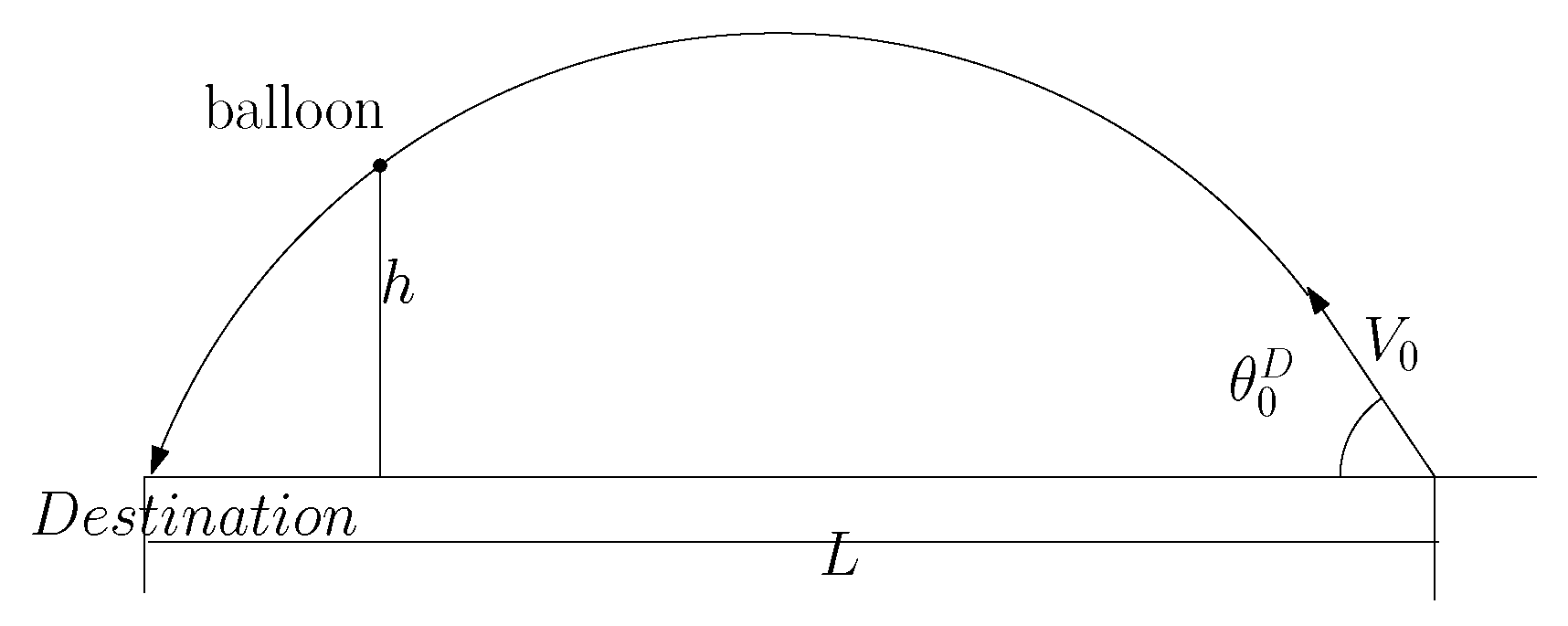
Before discussing the case of utilizing multiple balloons, we first consider a case where a single balloon is utilized for blocking the EP’s path. Let h denote the designated height of a balloon. See Figure 1 for an illustration of a single balloon at height h. The balloon is located to block the EP’s destination path.
Considering discrete-time systems, we next present how to simulate the path of the EP, as the initial shooting angle is given. At time-step 0, the EP is at the origin. Let denote the sampling interval.
At each time-step k, the EP’s velocity and pitch angle are updated utilizing
Here, presents the yaw angle of the destination with respect to the origin. In other words, is given as
In (8), is utilized to return a correct and unambiguous value for the phase angle in converting from Cartesian coordinates to polar coordinates. Equivalently, is the argument (also called phase or angle) of the complex number .
While simulating the EP’s motion utilizing (7), we have the time moment when
Control of Multiple Balloons
We may have errors in the prediction of , V, or M of the EP. In practice, we cannot predict the EP’s path accurately before the EP is launched.
Recall that (6) and (7) are utilized to build the EP’s path with yaw angle . Furthermore, at time step 0, Equation (6) uses the velocity and the shooting angle .
Suppose that the true EP’s path is built with yaw angle where is a Gaussian noise with zero mean and variance . Suppose that the true EP’s path is built with the initial velocity , where is a Gaussian noise with zero mean and variance . Furthermore, suppose that the true EP’s path is built with the initial shooting angle , where is a Gaussian noise with zero mean and variance . We assume that noise factors , , and are known a priori.
Our strategy is to deploy multiple balloons so that they can block the EP’s feasible paths considering the variance mentioned in the previous paragraph. Suppose we have N balloons in total. In this case, we generate N feasible paths for the EP. We then deploy N balloons for blocking each feasible path, respectively.
In order to block the true EP’s path, Algorithm 1 is utilized. In this algorithm, one builds N feasible EP paths considering the noise factors , , and . In this algorithm, is used as a tuning constant. As increases, we disperse the balloons to cover a wider space. We then deploy N balloons for blocking each feasible path, respectively.
| Algorithm 1: Deployment of N balloons. |
| n = 1; |
| while n ≤ N do |
| Generate using normal distribution with mean 0 and variance ; |
| Generate using normal distribution with mean 0 and variance ; |
| Generate using normal distribution with mean 0 and variance ; |
| ; |
| ; |
| ; |
| Using (6) and (7), build the EP’s feasible path with yaw angle , velocity , and shooting angle ; |
| Derive the time moment when (9) is satisfied; |
| The designated point is derived; |
| The n-th balloon is controlled to reach its designated point ; |
| n = n + 1; |
| end while |
After simulating the EP’s motion in Algorithm 1, is set as the designated blocking point for every balloon. Each balloon is controlled to reach its designated blocking point based on the controls in [12,13]. The control of a balloon is not within the scope of this paper.
Each balloon is equipped with IR sensors for detecting an incoming EP. Once the EP is sufficiently close to a balloon, the balloon explodes to neutralize the EP. Because the EP’s purpose is to reach its destination, the balloons can effectively intercept the EP under this method.
5. MATLAB Simulation Results
We verify the effectiveness of our multi-balloon systems using MATLAB simulations.
Simulation settings are as follows. The sampling interval is s. We use in Algorithm 1. Furthermore, we set m. We say that the EP is neutralized by a balloon as the distance between the EP and the balloon is shorter than 10 m. In the case where the EP is not neutralized by any balloon, it hits the ground in the end.
The initial position of the EP is at the origin. The initial EP velocity is 326 m/s. The destination of the EP is located at .
In simulations, the true EP’s path uses its proportional factor as . The EP’s path is built with yaw angle , where is a Gaussian noise with zero mean and variance . The EP’s path is built with the initial velocity , where is a Gaussian noise with zero mean and variance . The EP’s path is built with the initial shooting angle , where is a Gaussian noise with zero mean and variance .
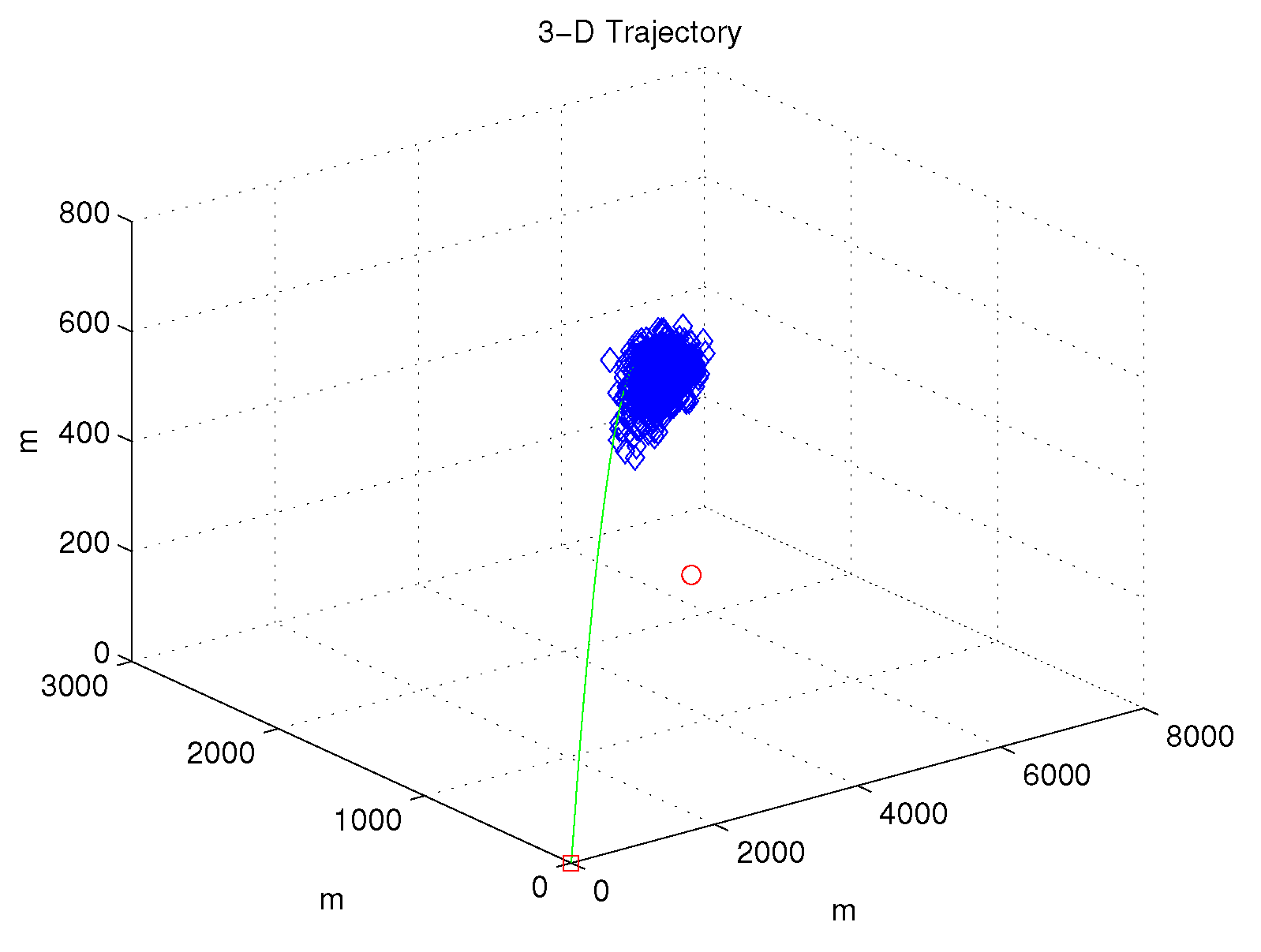
Figure 2 shows the case where balloons are deployed in total. In this figure, we use = 0.5 degree, = 0.5 degree, and = 0.1 m/s. The EP’s path is depicted with a green curve. balloons are marked with blue diamonds. See that balloons are deployed to block the EP’s path. The destination of the EP is marked with a red circle. The EP is neutralized by a balloon, thus it cannot reach its destination (red circle).
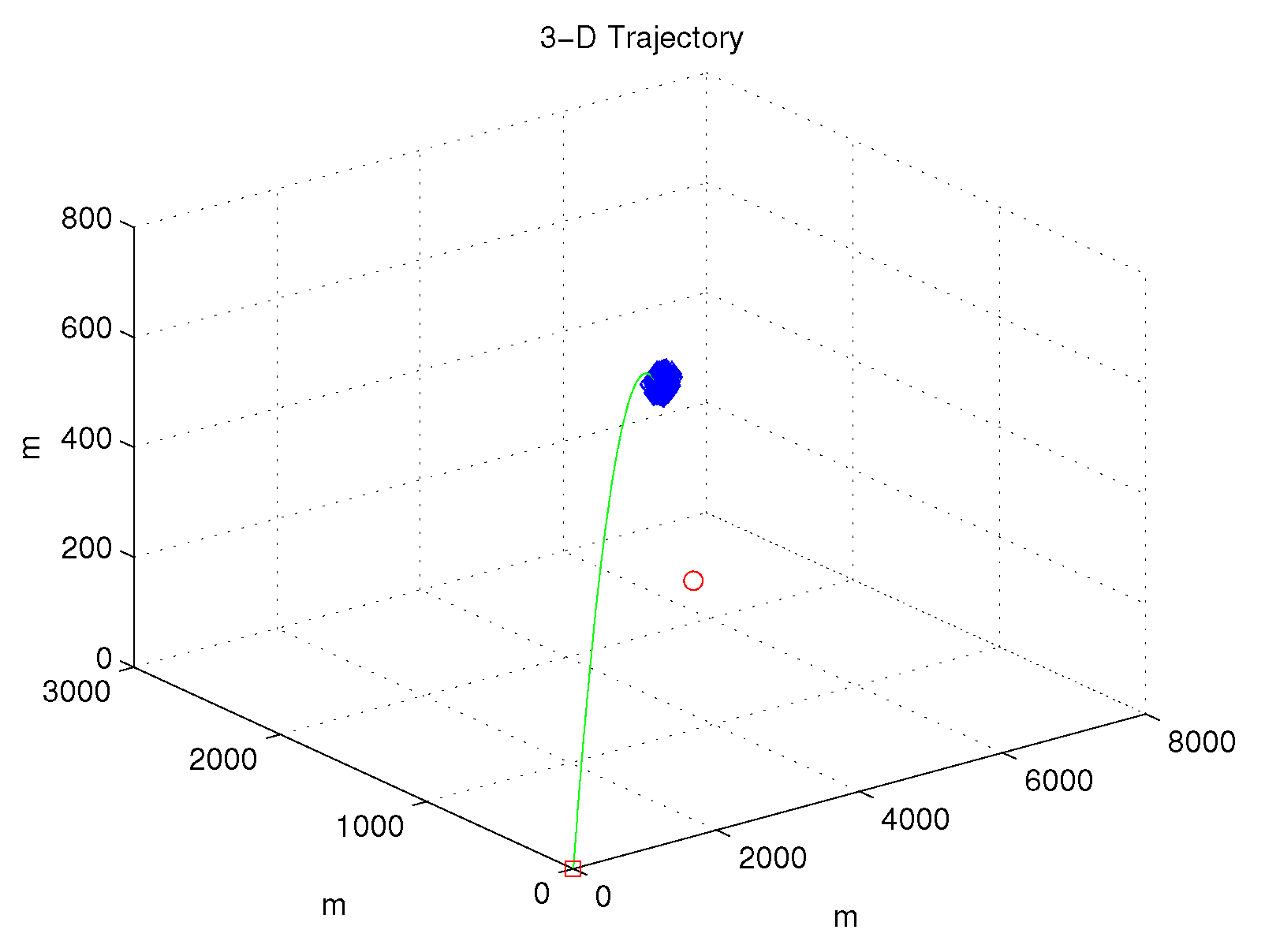
Next, we show the effect of varying the noise factors , , and . In Figure 3, we use = 0.1 degree, = 0.1 degree, and = 0.1 m/s. Figure 3 shows the case where balloons are deployed in total. The path of the EP is depicted with a green curve. balloons are marked with blue diamonds. Compared to Figure 2, the dispersion of the balloons decreased because we used decreased noise factors.
Next, Table 1 shows the effect of changing N. While changing N, one uses = 0.5 degree, = 0.5 degree, and = 0.1 m/s. We run 20 Monte Carlo (MC) simulations and check how many times the EP is neutralized successfully. Let BlockNum denote how many times the EP is neutralized among 20 MC simulations. Table 1 shows that as the number of balloons increases, increases.
6. Discussion on Balloon Deployment Positions
This paper considered the case where a balloon is deployed at a designated height h. Suppose that we want to block an EP when the distance between the EP and the EP’s destination is B. B is set as a sufficiently large value, in order to avoid the case where the explosion of an EP damages the EP’s destination. Instead of (9), we can use
7. Conclusions
This paper addresses a defense strategy against an EP trying to reach a known destination. The proposed defense strategy is positioning multiple balloons on the EP’s feasible paths so that they block the incoming EP. The balloons can effectively capture the EP under this blocking strategy. As far as we know, this article is novel in utilizing multiple balloons for protection against an EP. In the future, we will do experiments to verify the effectiveness of the proposed strategy.
Suppose that an EP is launched and that we have ground radar systems to measure the position of a moving EP in real-time. Using the EP’s position information, we can make a balloon move towards the moving EP. By making a balloon move towards an incoming EP, we can increase the possibility that the EP is captured by the balloon. In the future, we will handle how to make a balloon move towards the EP, considering the case where the EP position is measured in real-time.
Funding
This work was supported by the National Research Foundation of Korea (NRF) grant funded by the Korea government (MSIT) (No. 2019R1F1A1063151).
Institutional Review Board Statement
Not applicable.
Informed Consent Statement
Not applicable.
Data Availability Statement
Not applicable.
Conflicts of Interest
The author declares no conflict of interest.
References
- Shneydor, N.A. Missile Guidance and Pursuit-Kinematics, Dynamics and Control; Woodhead Publishing: Sawston, UK, 1998. [Google Scholar]
- Kim, J. Three-dimensional discrete-time controller to intercept a targeted UAV using a capture net towed by multiple aerial robots. IET Radar Sonar Navig. 2019, 13, 682–688. [Google Scholar] [CrossRef]
- Anderson, A.J.; McOwan, P.W. Model of a predatory stealth behaviour camouflaging motion. Proc. R. Soc. London Ser. B Biol. Sci. 2003, 270, 489–495. [Google Scholar] [CrossRef] [PubMed] [Green Version]
- Kim, J. Controllers to Chase a High-Speed Evader Using a Pursuer with Variable Speed. Appl. Sci. 2018, 8, 1976. [Google Scholar] [CrossRef] [Green Version]
- Rano, I. Direct collocation for two dimensional motion camouflage with non-holonomic, velocity and acceleration constraints. In Proceedings of the IEEE International Conference on Robotics and Biomimetics (ROBIO), Shenzhen, China, 12–14 December 2013; pp. 109–114. [Google Scholar] [CrossRef]
- Halder, U.; Dey, B. Biomimetic Algorithms for Coordinated Motion: Theory and Implementation. In Proceedings of the International Conference on Robotics and Automation (ICRA), Seattle, WA, USA, 26–30 May 2015; pp. 5426–5432. [Google Scholar]
- Song, S.; Ha, I. A lyapunov-like approach to performance analysis of 3-dimensional pure PNG laws. IEEE Trans. Aerosp. Electron. Syst. 1994, 30, 238–248. [Google Scholar] [CrossRef]
- Aggarwal, R.K.; Moore, C.R. Nonlinear CLOS guidance for missiles. In Proceedings of the 24th IEEE Conference on Decision and Control, Fort Lauderdale, FL, USA, 11–13 December 1985; pp. 667–668. [Google Scholar]
- Lin, C.-M.; Mon, Y.-J. Fuzzy-logic-based CLOS guidance law design. IEEE Trans. Aerosp. Electron. Syst. 2001, 37, 719–727. [Google Scholar] [CrossRef]
- Jeon, I.S.; Lee, J.I.; Tahk, M.J. Homing guidance law for cooperative attack of multiple missiles. J. Guid. Control. Dyn. 2010, 33, 275–280. [Google Scholar] [CrossRef]
- Kumar, S.R.; Ghose, D. Cooperative Rendezvous Guidance using Sliding Mode Control for Interception of Stationary Targets. In IFAC Proceedings Volumes, Proceedings of the 3rd International Conference on Advances in Control and Optimization of Dynamical Systems, Kanpur, India, 13–15 March 2014; Elsevier: Amsterdam, The Netherlands, 2014; Volume 47, pp. 477–483. [Google Scholar]
- Aaron, K.; Heun, M.; Nock, K. A method for balloon trajectory control. Adv. Space Res. 2002, 30, 1227–1232. [Google Scholar] [CrossRef]
- Ramesh, S.S.; Ma, J.; Lim, K.M.; Lee, H.P.; Khoo, B.C. Numerical evaluation of station-keeping strategies for stratospheric balloons. Aerosp. Sci. Technol. 2018, 80, 288–300. [Google Scholar] [CrossRef]
- Chudinov, P.S. Approximate Analytical Investigation of Projectile Motion in a Medium with Quadratic Drag Force. Int. J. Sport. Sci. Eng. 2011, 5, 27–42. [Google Scholar]
Figure 1.
A balloon at height h. The balloon blocks the EP’s path for reaching its destination.

Figure 2.
Simulation result using = 0.5 degree, = 0.5 degree, and = 0.1 m/s.

Figure 3.
Simulation result using = 0.1 degree, = 0.1 degree, and = 0.1 m/s.


Table 1.
The effect of changing N.
| N | BlockNum |
|---|---|
| 100 | 8 |
| 500 | 18 |
| 1000 | 19 |
Publisher’s Note: MDPI stays neutral with regard to jurisdictional claims in published maps and institutional affiliations. |
© 2021 by the author. Licensee MDPI, Basel, Switzerland. This article is an open access article distributed under the terms and conditions of the Creative Commons Attribution (CC BY) license (https://creativecommons.org/licenses/by/4.0/).
Share and Cite
MDPI and ACS Style
Kim, J. Autonomous Balloon Controls for Protection against Projectiles with Known Destinations. Appl. Sci. 2021, 11, 4077. https://doi.org/10.3390/app11094077
AMA Style
Kim J. Autonomous Balloon Controls for Protection against Projectiles with Known Destinations. Applied Sciences. 2021; 11(9):4077. https://doi.org/10.3390/app11094077
Chicago/Turabian StyleKim, Jonghoek. 2021. "Autonomous Balloon Controls for Protection against Projectiles with Known Destinations" Applied Sciences 11, no. 9: 4077. https://doi.org/10.3390/app11094077
Note that from the first issue of 2016, this journal uses article numbers instead of page numbers. See further details here.