
An Inspection of IFC Models from Practice


3D Geoinformation, Delft University of Technology, Julianalaan 134, 2628 BL Delft, The Netherlands
*
Author to whom correspondence should be addressed.
Appl. Sci. 2021, 11(5), 2232; https://doi.org/10.3390/app11052232
Submission received: 29 December 2020
/
Revised: 19 February 2021
/
Accepted: 23 February 2021
/
Published: 3 March 2021
(This article belongs to the Special Issue BIM and HBIM: Principles, Applications, and Standardization/Interoperability Issues)
Abstract
:Industry Foundation Classes (IFC) is a complete, wide and complex open standard data model to represent Building Information Models. Big efforts are being made by the standardization organization buildingSMART, to develop and maintain this standard in collaboration with researchers, companies and institutions. However, when trying to use IFC models from practice for automatic analysis, some issues emerge, as a consequence of a misalignment between what is prescribed by, or available in, the standard with the data sets that are produced in practice. In this study, a sample of models produced by practitioners for aims different from their explicit use within automatic processing tools is inspected and analyzed. The aim is to find common patterns in data set from practice and their possible discrepancies with the standard, in order to find ways to address such discrepancies in a next step. In particular, it is noticeable that the overall quality of the models requires specific additional care by the modellers before relying on them for automatic analysis, and a high level of variability is present concerning the storage of some relevant information (such as georeferencing).
1. Introduction
Interoperability is a key feature for data to be exchanged and (re)used in new-generation applications for the planning, building, analysis and management of cities, as well as for collaboration and communication. Among such data, an important source of information about the built environment are Building Information Models (BIMs). They were developed in the Architecture Engineering and Construction (AEC) field approximately from the 1980s, as an evolution of Computer Aided Design (CAD) tools, and have become more popular during the last 20 years, with the development of cheaper and more powerful computers, and more effective tools to model and manage BIMs.
The original scope of such (often 3D) information systems is to support a building’s design and construction. However, current BIM models are supposed to be useful for much more than this narrow purpose, representing a central platform for collaboration during the design phase of a building (architectural design, structural design, installations design, etc.), supporting coordination between disciplines and analysis of the designed building within the same modelling tool or within compatible ones, and once built, being a base data set that can be reused and maintained to support the asset and facility management of the modelled object.
Great advantages would be brought by an effective interoperability of such data. These would involve many scopes. First of all, the collaboration among different kinds of practitioners involved in building design, construction and management. Second, the exchange and reuse of the data among different stakeholders and through time. Third, the integration with other data sets, including different formats, for various use cases (e.g., map updates, energy analysis, building permits issuing, materials documentation and so on). For instance, an often discussed integration is the one with 3D city models and other types of geoinformation (GeoBIM), cf. [1,2,3,4,5,6,7,8,9,10,11,12,13,14,15,16,17].
One solution to realize these potentials could be the use of the same native format produced by (mostly proprietary) BIM software. However, from the point of view of developers and users, a more preferable and realistic solution would be the use of open standard formats; in particular, for BIM, the Industry Foundation Classes (IFC) (https://technical.buildingsmart.org/standards/ifc/, accessed on 1 March 2021) which were developed by the buildingSMART consortium (https://www.buildingsmart.org, accessed on 1 March 2021) (Section 2). This approach ensures an equal footing for different software vendors and avoids vendor lock-in for users. The use of open standard formats is also preferable in the case of integration with data sets from different fields or in different formats, where potential users might not have any software that is capable of reading a given proprietary format.
However, some issues can still be encountered when producing [18,19] and exchanging standardized data among software and people (such as incompleteness of the models, inaccuracies, different semantics interpretations, geometry deformations) [20,21,22,23,24], which could prevent a smooth exchange of information as well as the use of data within automatic processing [25,26]. It is fundamental to overcome such problems and uncertainties to build interoperability on a solid base, for which the first step is the understanding of the state of the art.
To connect to what is the current practice in the modelling and exporting of standardized BIM data by practitioners, a sample of BIMs, modelled within practitioners’ design projects and provided in the IFC format, was inspected and analyzed (Section 4). The aim was to understand what are their most common formal characteristics (Section 5.1 and Section 5.2), storage of georeferencing information (Section 5.3), definition of semantics (Section 5.4), modelling and organization (such as grouping) of geometries (Section 5.5) and possible further observations. This knowledge can help in (further) developing solutions for automated use of BIM data in practice.
2. Industry Foundation Classes
As synthesized by Noardo et al. [23], the open standard data model for BIM is the buildingSMART Industry Foundation Classes (IFC) [27]. It is intended to comprehensively cover the data requirements in many domains and use cases within the Architecture Engineering and Construction (AEC) and Facility Management (FM) fields, such as building components and processes, describing both physical and abstract concepts (e.g., cost, schedule, etc.).
2.1. IFC Semantics
IFC semantics are structured in a deeply hierarchical data model, additionally organized in meronymic (part-of) trees too. Spatial composition, by means of IfcSpatialStructureElements (https://standards.buildingsmart.org/IFC/RELEASE/IFC4/ADD1/HTML/schema/ifcproductextension/lexical/ifcspatialstructureelement.htm, accessed on 1 March 2021) (Site/Building/Storey/Space/Zone) is one more kind of aggregation, different from the element (meronymical) composition one (e.g., a stair and the assembled elements in it). IfcSpatialStructureElement is used to define a spatial units structure, by means of which the building project is organized. In addition, various forms of semantic information can be associated to the elements, such as materials, properties (key-value pairs) and even scheduling. Elements are also related to one another, for example for wall connectivity and space boundaries.
Moreover, it is often possible to store the same kind of object by means of several entities. For example, the layers within a compound wall object can be represented by means of an associated IfcMaterialLayerSet, but also as a more generic decomposition where every wall layer is modelled as a distinct IfcBuildingElementPart.
Many attributes can be provided for elements, as foreseen by class specifications that can be inherited from their parents. In addition, property sets (already in the standard or added as extension) can be used.
This semantic complexity is intended to represent faithfully the buildings as functional to the designed scope. However, the implementation and use of such theoretically precise models is difficult and can result in inaccuracies or the underuse of the most complex features, besides hindering interoperability by providing a very high degree of freedom to fill in the information in different ways and by choosing one of the many possible kinds of representations that can be used [23].
In order to define subsets of the IFC models to be implemented, the Information Delivery Manual (IDM) is added as part of the buildingSMART standard. It defines the workflow and the information exchange specifications and requirements for needed use cases. From each IDM, a set of Model View Definitions (MVDs) can be defined for identifying the portion of the IFC model which is needed for the information exchange described in the IDM to be fulfilled.
The documentation of an MVD allows the exchange to be repeated, providing consistency and predictability across a variety of projects and software platforms. MVDs are provided as part of the IFC releases and mostly implemented by software are the ‘Coordination view’ for IFC 2x3 and the ‘Design Transfer view’ and ‘Reference view’ for IFC 4. These different views differentiate whether a model is intended as a static reference (IFC4 ReferenceView) or as a parametric model to transfer the design intent (IFC4 DesignTransferView). In the first case, geometrical definitions are much simpler and explicit, whereas in the latter case, it will require the application of much more geometric processing (such as Boolean set operations and sweeps) to come to an evaluation of the geometrical form of the model.
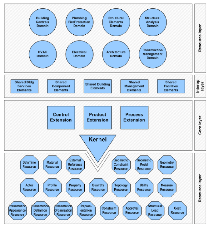
The concepts represented in IFC are organized in four conceptual layers, as represented in Figure 1.
The core layer contains the classes which are central and most general in the data model. In particular, the Kernel contains the root classes for the definition of objects, relationships and properties and their relationships (e.g., IfcRoot, superclass of all the other entities; IfcRelationship, superclass of all relationships; IfcObject, which is the parent entity of IfcGroup, IfcActor, IfcResource, IfcControl, IfcProcess, IfcProject and IfcProduct, being specified in the further extensions of the model). In the core layer there are also the three main extensions representing the foreseen possible representations by IFC: product, control and process.
The interoperability layer includes classes specializing those defined in the IfcProductExtension schema, increasing the level of detail of the represented information. The included entities can be of interest to multiple domains.
Some even more specific information can be represented through the domain specific part of the schema, which can specify either classes represented in the interoperability layer or in the product extension directly (IfcArchitectureDomain, IfcBuildingControlsDomain, IfcConstructionMgmtDomain, IfcElectricalDomain, IfcHvacDomain, IfcPlumbingFireProtectionDomain, IfcStructuralAnalysisDomain, IfcStructuralElementsDomain).
The resource layer includes entities to further describe the objects defined in the other levels.
In order to represent objects which are not included in the IFC model, an IfcProxy element is foreseen, as a subclass of IfcProduct. In particular, the entity IfcBuildingElementProxy is frequently used in models to substitute other entities. This is useful in order not to prevent the addition of customized entities to models. However, many times this is instead used (or misused) to also represent objects which have suitable entities in the IFC model. This is a problem, since a correct interpretation of such models from the semantic point of view becomes more difficult, requiring either manual work or complex inferences based on their geometry.
This is why one of the aspects we analyzed in our study was the proper use of the entity IfcBuildingElementProxy.
2.2. IFC Georeferencing
Despite some increased use, georeferencing is still not a common practice among building designers, for whose aims a local system is usually preferable, implying the use of Cartesian coordinates with small and more manageable values. Building Information Modelling software works better as well with such close-to-origin Cartesian coordinates, as the precision of floating point numbers is dependent on their distance from the origin.
However, properly georeferencing an IFC file makes it possible to link the (local) coordinates inside an IFC model with the corresponding coordinates of the real-world location, and thus to place the model of a single building or construction within its planned context, related to other existing and planned objects and any relevant environmental factors. For this reason, more and more studies address the need for georeferencing BIM and storing such information in the IFC files themselves [28,29,30], including by a buildingSMART working group (https://www.buildingsmart.org/wp-content/uploads/2020/02/User-Guide-for-Geo-referencing-in-IFC-v2.0.pdf, accessed on 1 March 2021).
There are several options to store georeferencing information in IFC, as described by Clemen and Görne [31]. These options range from basic address information to the definition of a more detailed position referred to a projected coordinate reference system (CRS). In this last case, an offset can be stored between the project coordinate system and the global origin of a CRS (X, Y and height). The rotation of the -plane is also included (Table 1).
However, those levels do not necessarily indicate a scale measuring the quality of georeferencing, but they are mostly relevant to identify how the information is stored. In fact, in some cases, the accuracy of different LoGeoRefs can be absolutely similar (e.g., LoGeoRef30 and LoGeoRef40), since the values are supposed to be the same, but stored differently within the IFC file.
A further note is useful about the storage of the model reference system direction. In the LoGeoRef40 the stored direction represents the TrueNorth (https://standards.buildingsmart.org/IFC/RELEASE/IFC2x2/FINAL/HTML/ifcrepresentationresource/lexical/ifcgeometricrepresentationcontext.html, accessed on 1 March 2021) attribute, defined as “direction of the true north relative to the world coordinate system as established by the representation context”. As also cited in the buildingSMART document about georeferencing (https://www.buildingsmart.org/wp-content/uploads/2020/02/User-Guide-for-Geo-referencing-in-IFC-v2.0.pdf, accessed on 1 March 2021), this could be different from the grid North, considering a Cartesian system and possibly stored as part of the IfcObjectPlacement within IfcSite (inherited from the class IfcSpatialStructureElement and, in turn, IfcProduct), according to LoGeoRef30. As defined in the IFC specifications (https://standards.buildingsmart.org/IFC/RELEASE/IFC2x/ADD1/HTML/ifcgeometricconstraintresource/lexical/ifcobjectplacement.html, accessed on 1 March 2021) “The object placement can be given: absolute (i.e., by an axis2 placement, relative to the world coordinate system); relative (i.e., by an axis2 placement, relative to the object placement of another product); by grid reference (i.e., by the virtual intersection and reference direction given by two axes of a design grid). In any case the object placement has to unambiguously define the object coordinate system as either two-dimensional axis placement (IfcAxis2Placement2D) or three-dimensional axis placement (IfcAxis2Placement3D)”.
In the case of IfcSite, usually it is specified as IfcLocalPlacement (https://standards.buildingsmart.org/IFC/RELEASE/IFC2x/ADD1/HTML/ifcgeometricconstraintresource/lexical/ifclocalplacement.html, accessed on 1 March 2021), with attributes: PlacementRelTo (which, if omitted, indicates the World Coordinate System to be in theory defined within the geometric representation context) and RelativePlacement, filled by means of an IfcAxis2Placement class, specified as IfcAxis2Placement3D (https://standards.buildingsmart.org/IFC/RELEASE/IFC2x/ADD1/HTML/ifcgeometryresource/lexical/ifcaxis2placement3d.html, accessed on 1 March 2021). There, the attributes represented are usually: Location (inherited by IfcPlacement and stored as IfcCartesianPoint); Axis (representing the direction of the local Z axis); RefDirection, storing the direction of the X axis. It is relevant to note that in this case the direction of X is stored, whilst in the LoGeoRef40 case, under IfcGeometricRepresentationContext—TrueNorth attribute, the Y direction of a possible Cartesian system is stored. Therefore, the values of two vectors composing the IfcDirection are inverted in the two cases. This must be considered when developing software applications reading the data in the two cases.
In the specifications, it is established that, whether omitted, the reference should be the geometric coordinate system (used in LoGeoRef40). It is therefore necessary to be careful in the priority given to the information stored in the two systems: LoGeoRef30 should be read first, if absent, then go to LoGeoRef40.
2.3. IFC Modelling
Parametric modelling is usually employed in BIM and IFC, which makes it possible to encode many kinds of geometries. The IFC geometry is mostly defined or derived from a different standard, i.e., ISO [32], which also specifies the STEP Physical File (SPF).
Interoperability is affected by the kind of modelling and geometry used, since software can implement only subsets of the allowed ones, to adopt different conventions for their description and coding (e.g., extrusion directions, Boolean operations, etc.), or even to choose to support additional kinds of geometries with respect to the group identified in standard prescriptions [23].
Furthermore, the way designers model the BIM can have consequences for the interoperability with other formats: especially, conversion procedures should define the allowed objects and agree on other modelling specifications. Inaccuracies, such as intersections or gaps between geometries, can also produce issues with respect to automatic processing.
Two constructs (and related IFC classes) are particularly important: IfcOpenings and IfcSpaces.
Subtraction relationships are part of the IFC model, representing openings by means of the voiding mechanism: IfcOpening defines the objects used to be subtracted from another geometry (e.g., an IfcWall or an IfcSlab) in order to generate an opening in a consistent way, according to the data model. The IfcOpening can be in turn filled by an element, like an IfcWindow or IfcDoor.
A second important element is the explicit modelling of IfcSpaces, which are filling the empty spaces (for example, rooms) and defining them. It is possible to associate attributes to them, and their geometry is generally very relevant to conversion procedures.
2.4. Disciplinary Models and Federated Model
BIMs are usually split into several models, each of which describe the information related to a design discipline: architectural, structural, installations [33]. They are combined together in a federated model.
For using the BIM, and in particular the IFC files representing each model, which are separately exported, it is important to know what to expect within each model: what elements are included and which ones are not. Note that these are potentially sharing the same space.
The correct merger of multiple models into one is important for many use cases. For example, the computation of routes within the building should consider all the walls, whether they are load-bearing or not, and the calculation of volumes and heights have to count on all walls and slabs. Additionally, with respect to integration with geoinformation, it is important to know which surrounding elements from the context where the building is designed are stored in the BIM. Another example is the computation of the maximum envelope of the building, such as for building permit regulation checks [30], where all the elements that extend towards the outside of the building should be included (e.g., chimneys and balconies).
Unfortunately for interoperability, a unique subdivision of elements within such models is neither provided by standardization nor by shared practice. Instead, requirements and specifications are defined in each call for tenders according to the specific requirements of a particular use case. Although suboptimal, it is currently the most reasonable choice in order for users to obtain exactly the representation(s) they need. However, it means that: first, the elements can be stored in any of the models composing the federated one; and second, an element (such as a slab or a wall or an installation part) can be stored redundantly (and possibly inconsistently) within several discipline models. Arguably, in these circumstances, a validity checker should not detect the duplication of the same elements as a clash. Due to the way references between elements are stored within IFC models, in most cases, references can only be made between elements stored in the same file. This can cause issues when one depends on relationships (such as space boundaries) when the elements are contained in distinct aspect models. Krijnen et al. [34] provides options to later infer such relationships.
The developers of tools to automatically process IFC models should consider this practice and possibly propose guidelines and prescriptions about the objects to be included in the representation for each case, or about how to document the modelling choices as machine-readable metadata.
3. The Importance of IFC Models Quality for IFC Data Downstream Automation Use Cases
An insight into the use cases that rely on IFC models further explains the relevance of outlining the current state of the models. More focused quality requirements can then be recommended consequently. The use cases for which the BIMs and the IFC data model were conceived can be many, as it is even possible to read in the buildingSMART website (https://technical.buildingsmart.org/standards/ifc/, accessed on 1 March 2021): “IFC can define physical components of buildings, manufactured products, mechanical/electrical systems, as well as more abstract structural analysis models, energy analysis models, cost breakdowns, work schedules, and much, much more.”
Building design, which is the priority use case, requires elements to be modelled correctly and clear geometries to be generated. This use case foresees the cooperation of several professionals around the same building. Therefore, it is necessary that each of them models elements accurately, such that clashes between different models reflect design problems that need to be fixed, and if no clashes occur, they should not occur in the real world either.
On the other hand, one of the most frequent current uses of IFC models is visualization, for which few quality requirements are necessary, as long as the elements of interest can be viewed correctly. An approximate georeferencing to the correct location and orientation can improve visualization, but a few meters of tolerance usually make little difference, depending on the context. However, the overarching aim of building information modelling, as well as any other information system, is the automation of tasks and analysis. Therefore, additional applications (other than visualization) must be taken into account.
The automatic calculation of building costs [35,36] requires an accurate definition of semantics, including the correct storage of elements within IFC classes and the association of correct attributes related to the specific element properties, materials, and possible references to fabrication details. In addition, such elements must be modelled correctly, avoiding clashes and intersections, since this could lead to inaccuracies, whose importance vary together with the dimension and complexity of the building. Georeferencing is usually not very important in this case, with only minor dependent factors, such as the transport of building materials.
For the structural analysis use case [37,38], it is important to model the building elements with their correct semantics and correct geometry, and to associate the correct attributes about material structural properties and their design as load-bearing elements or not. The relevant grouping of elements, in this case, is about the identification of each structural-independent building or part of it. It can be effectively represented by means of IfcBuilding. Georeferencing is not relevant in this case either.
Energy simulations [39,40] need an accurate modelling of the building envelope, information about building form, materials’ physical properties, the internal layout and the space boundary connectivity to support the building energy performance calculations, implying good semantics to correctly identify building elements (entities) and to describe their properties. Krijnen et al. [34] shows that many of the assessed models did have errors in their definitions of space boundaries. Luttun and Krijnen [41] shows that many of the assessed models did have errors in their labelling of external elements (the ‘IsExternal’ property). In addition, the correct identification of building units and their function are important, as well as the modelling of spaces and thermal zoning in particular (possibly as IfcZones in version 4 of IFC). The accuracy of geometry is important as well (Maile et al. [42] describe it together with some of the usual errors of IFC models). These are necessary to perform a correct assessment of the energy requirements according to the occupancy of the building (which has to be stored as well). As a counterpart to this, climate parameters and information related to the planned geographic location of the building are useful (i.e., maximum and minimum temperatures in summer and winter, wind speed, humidity, etc.). The accuracy required for retrieving such information is not a centimeter-precision position of the building (as given by an accurate georeferencing), but mostly the identification of the city where it will be built, together with the orientation of the building is sufficient. However, a building’s context and its surrounding buildings could affect its energy use indirectly (e.g., by reducing a building’s exposure to wind or blocking sunlight).
Urban planning and building permit issuing is a further relevant use case, which is likely to become more and more automated in the future [43]. A number of different analyses are required to check a design against relevant regulations (e.g., building codes and city ordinances), and the BIM provided as a set of IFC files is likely to be processed by different tools to check them. For this reason, a comprehensive good quality of the models is essential [30,44,45,46,47]. Entities have to be correctly identified by IFC classes; grouped consistently as IfcSite, IfcBuilding, IfcBuildingStoreys; their grouping as apartments or similar building units would also be appropriate; spaces should be modelled correctly, possibly with the association of functions or foreseen use, since many rules are based on such information, which is also hard to infer in an automated process. The geometry should also follow known criteria and avoid irregularities, such as intersections, redundancies, gaps, unforeseen kinds of storage (as boundary representation, solids, etc.) and so on. Any error can prevent the success of automatic processing, such as: the measurements of rooms, doors and other elements to check accessibility and minimum dimensions requirements; the identification and calculation of paths and routes necessary for emergency evacuations or other uses; the extraction of the building envelope to define external dimensions, as useful for regulations checking facades and other outer elements; volumes and surfaces measurements as input to further checks (for example, the parking places to be provided, the taxes and fees to be paid for the constructions, amount of green areas to be designed, in some cases). The attributes necessary in this case can vary and an exhaustive list could be provided case by case, as a consequence of the applied regulations and used tools. Since the integration with geoinformation represents a strong opportunity and a necessity for checking many regulations, an accurate georeferencing is also essential.
Finally, the conversion use case, also as a basis for integration with further data sets from other fields, including geoinformation, gains from (and is enabled by) a good quality of the IFC models [10]. However, specific relevance has to be awarded to the representation and storage of geometries. Geometric clashes between elements will significantly impede fully automated conversions, since it is not possible to know which element is actually present at a given location. Gaps are also a problem, since elements need to fully enclose spaces, such as rooms, in order for their correct semantics to be automatically derived from the model. Grouping can also be useful to isolate the elements to be converted to autonomous objects. The correct assignments of semantic classes is also necessary to support the automated mapping, as well as attributes, for any kind of translation of the present information. An accurate georeferencing information is again the premise for a correct conversion to and integration with georeferenced data. Because of the needs pointed out by these use cases, the IFC features checked within this study are selected as relevant.
4. Methodology
In order to understand in more detail how those IFC features are reflected in data generated in practice, as a result of the modellers’ choices combined with the used software settings and implementation, a sample of models coming from practice (Section 4.1) were inspected and analyzed in a structured way.
First of all, the formal aspects of the data were considered, such as the used modeling software and IFC version and Model View Definition (see Section 2.1).
A second part of the inspection regards more technical and contents aspects. In particular, the features that could affect interoperability and conversion to other formats were considered: storage of georeferencing (Section 4.2), semantics (Section 4.3.1), modelling (Section 4.3.2).
The methodology adopted for this study is based on the manual inspection of the sample of models, both by checking the text of the EXPRESS format within text editors and within IFC viewers, such as the RDF IfcViewer (http://rdf.bg/product-list/ifc-engine/ifc-viewer/, accessed on 1 March 2021) and Solibri Model Viewer (https://www.solibri.com/solibri-anywhere, accessed on 1 March 2021).
4.1. The Sample of Models
The used sample of BIMs was composed by 57 models coming from different sources and nations. They were in-kind provided by designers and organizations involved in research projects mainly regarding BIM and GeoBIM topics (e.g., the EuroSDR GeoBIM project (https://3d.bk.tudelft.nl/projects/eurosdr-geobim/, accessed on 1 March 2021), the GeoBIM benchmark (https://3d.bk.tudelft.nl/projects/geobim-benchmark/, accessed on 1 March 2021), GeoBIM (https://3d.bk.tudelft.nl/projects/geobim/, accessed on 1 March 2021) and similar ones).
The models represented different kinds of objects: some buildings, some infrastructures (six models of a roundabout) and some which were in-between (e.g., a metro station). This could introduce some more inaccuracy in some of the comparisons. Table 2 shortly reports the features of the models that we inspected.
The models representing the same construction objects (i.e., part of the same federated model) having a common source, were most likely to be similar in modelling criteria and quality. Similarly, 10 architectural models were provided by the same source, representing the parts of a building complex in Amsterdam (n. 16 to 27 in Table A1) and they were likely to have similar features.
For the semantics and modelling assessments, the architectural and structural models were considered, including the model of the facade (n. 8c in Table A1).
The 11 models representing the installations were kept apart, for the inability of the authors of assessing the quality of representation and associated semantics. The installations models were instead considered together with the architectural and structural ones when looking at the grouping of entities in IfcSpatialStructures: IfcSite, IfcBuilding, IfcBuildingStoreys. One could argue how relevant it is to check their distribution in the storeys. However, installation analysis are out of the scope of this paper, while, since installations are physically part of the construction too, operations such as the extraction of the maximum envelope of a building, or similar geometric ones (e.g., maximum height), would be affected.
4.2. Storage of Georeferencing
The georeferencing of the models is a priority when dealing with GeoBIM integration, and it was therefore important to point out the current use of such a feature.
Two aspects were considered to analyze the storage of the georeferencing information: first, where the information was stored, according to the Levels of Georeferencing identified by Clemen and Görne [31], with LoGeoRef 0 in case there was no information at all. It was possible that such information was stored multiple times, according to different LoGeoRefs, since at present, no validation system exists to check that information stored according to different LoGeoRefs is kept consistent. An additional hinder for a possible validation is that it was not possible to store metadata related to the used coordinate reference system (CRS) in IFC v.2x3, unless the EPset_ProjectedCRS and EPset_MapConversion (https://forums.buildingsmart.org/t/geolocation-standards-in-ifc2x3-and-ifc4/2329, accessed on 1 March 2021) are used, which is not a very spread system though. Therefore, it would be hard to check reciprocal consistency.
The storage and quality of the information about North and East coordinates values, the elevation values and the rotation direction were checked and reported separately, since it resulted to be not very usual for the three of them to be stored consistently.
Moreover, the quality of the information stored in each level was checked with respect to the ground truth in the available documentation and classified as:
- Accurate: referring to the actual location of the construction (green in Table 3);
- Close approximation: identifying a point in the same city than the construction (yellow in the table);
- Far approximation: identifying a point in the same country than the construction (orange in the table);
- Wrong: (red in the table).
The height and direction, except for apparent errors, are considered correct, since we do not have the opportunity to check; the colour yellow indicates that it is slightly different among different discipline models of the same building.
4.3. Models Inspection
Reliable automatic tools to validate the models are unfortunately not available. Therefore, besides checking the presence, number and values of IFC classes by means of the NIST IFC analyzer (https://www.nist.gov/services-resources/software/ifc-file-analyzer accessed on 1 March 2021), the manual procedure was used, notwithstanding the implied subjectivity, approximation and partiality in the assessment, which were reduced as much as possible by defining criteria and scores, but which is not possible to remove completely.
In all the cases, 0.6 was considered the minimum score to allow the model to be used within automatic processing, although in many cases only the optimal (score 1) would support a completely successful result. The other scores were distributed accordingly.
4.3.1. Inspection and Assessment of Semantics
A correct use of semantics within the models is essential to select and retrieve the correct objects within models, as well as to possibly exclude some of them from calculations.
The most basic requirement is that the objects are stored by means of the correct IFC entity, which allows their consistent identification, although possible differences are due to slightly different interpretations of the IFC classes or various generalization levels (i.e., super-classes used instead of sub-classes).
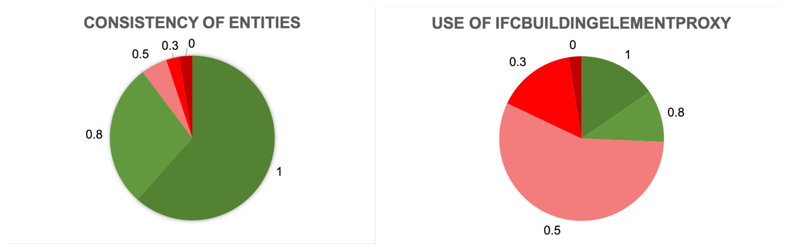
For this reason, the consistency of used entities with respect to the IFC data model definitions was checked, giving scores to the models as:
- 1: all correctly used;
- 0.8: correctly used, with few errors;
- 0.5: partially consistent;
- 0.3: few consistent entities;
- 0: completely wrong.
A second check with respect to the same aspect was about the use of IfcBuildingElementProxy, that is useful to include in the representation elements not foreseen by the IFC model, but can be wrongly used to substitute entities having a valid representation in IFC.
In this case, the scores were given as:
- 1 none used;
- 0.9 present but used correctly (that is, to represent entities not present in IFC);
- 0.5 some (i.e., only a couple of elements or kinds of elements) are used, instead of correct classes;
- 0.3 many different ones are used, instead of the correct classes;
- 0 all entities are IfcBuildingElementProxies.
The rich semantics allowed by BIM and IFC do not end with the use of entities, but a number of properties and attributes can additionally be an effective support for many use cases. In particular, materials and their own properties are essential to a number of applications (such as energy simulations, cost computations, noise simulation and so on). For this reason, a specific check was dedicated to this aspect.
However, it was hard to give scores because on the one hand, they could correctly include a varying number of attributes and properties, foreseen by the IFC schema or added as extensions. On the other hand, the information for each use case was very specific and it would be necessary to consider this in detail in order to give an appropriate overview about the completeness and suitability of the stored information.
Therefore, attributes were assessed as:
- 1: using many attributes fully true to the definition of the IFC schema (which appeared to be never the case);
- 0.9: using many attributes both foreseen by IFC and added custom ones;
- 0.8: using few attributes both foreseen by IFC and added custom ones;
- 0: not used at all.
For the reasons previously mentioned, in this part of the study, all the assigned scores were considered higher than the minimum requirements, except the case where there were no attributes at all.
Similarly, materials were just noted as present (1) or not present (0), plus a score “0.5” in the cases when they were present, but in a very inaccurate way, by means of few very general indications (such as just “wood”).
4.3.2. Inspection and Assessment of Object Modelling
The organization of the spatial structures (IfcSite, IfcBuilding, IfcBuildingStorey and IfcSpace) in the models was the first checked aspect.
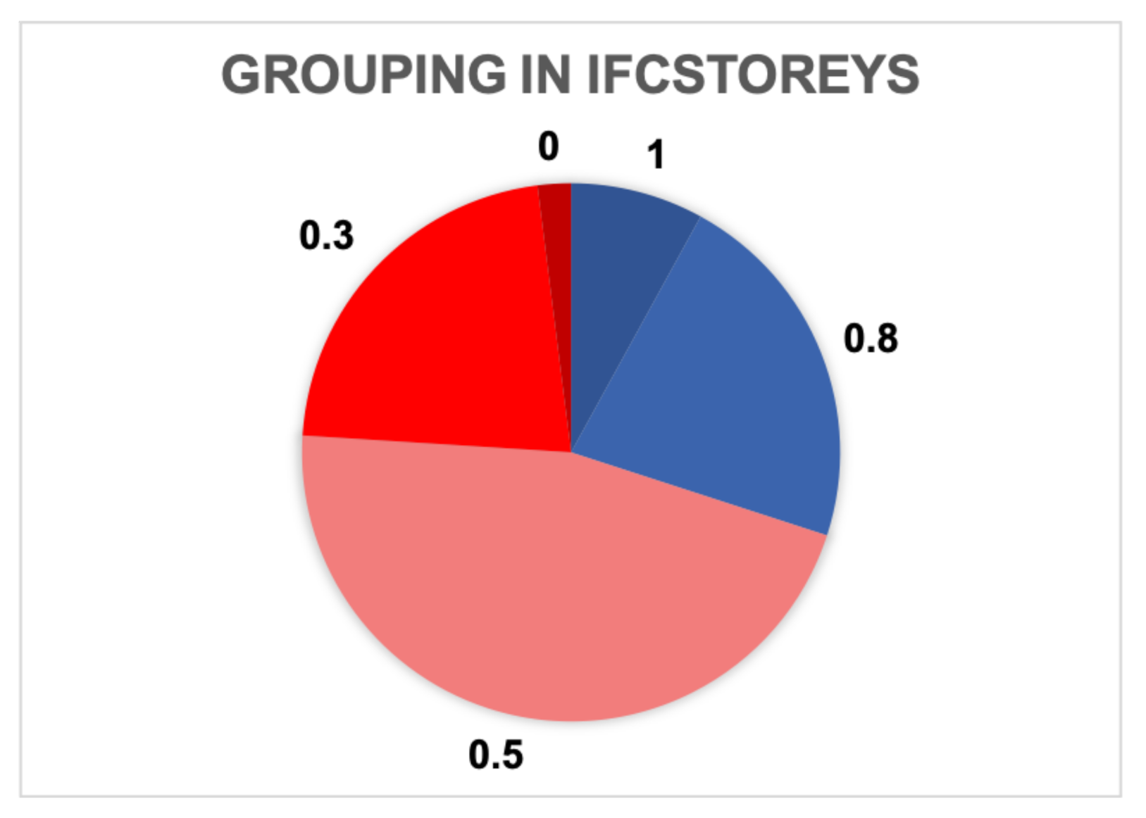
The grouping of IfcSite and IfcBuildings was generally very simple and no scoring system was necessary. Instead, scores are assigned to the grouping of IfcStoreys, which could be very helpful to simplify a number of processing, on the condition that they would be grouped consistently. The chosen scores were:
- 1: in case the storey contained only the elements belonging to the represented floor;
- 0.8: when the grouping was consistent although some elements ran for more than one storey due to their modelling nature. For example, some structural elements or installations or other building elements could occupy more than one storey, although being correctly modelled. Although not being an error, any processing relying on a consistent grouping of storeys was prevented.
- 0.5: with some inaccuracies (which could be fixed through quite simple processing);
- 0.3: very inaccurate;
- 0: not used at all.
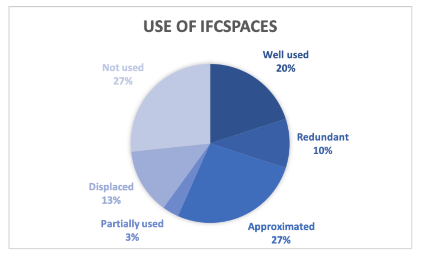
IfcSpace was the last assessed element about modelling. It was only assessed on the 30 architectural models, not including the facade model. Although a good modelling of spaces is a useful support to many use cases, different practices could be noted. We assessed the models on this aspect as:
- Well used;
- Redundant: overlapping spaces described different volumes, even hierarchical (e.g., room, apartment, floor, gross surface, net surface, gross volume, balcony and so on);
- Approximated: they did not follow the ceiling pitch but were an extrusion of the room floor to an approximated height;
- Partially used;
- Displaced: spaces appeared displaced with respect to their correct location;
- Not used.
It is still valuable to add that in some cases spaces were correctly stored as sub-group of IfcBuildingStorey, as implied by the IFC schema, while in others they were not. However, this may depend on the used modelling software, whose settings have an influence on how the models are exported to IFC. For example, in the models exported by Autodesk Revit this generally did not occur. Moreover, in 13 out of 30 models, IfcSpaceBoundaries were represented in addition, describing the surfaces enclosing the space volume.
Other considerations regarding the geometries modelling: the geometry was inspected by means of the IFC viewers, to check the most apparent features. However, it is hard to give exhaustive comments on it, since a tool systematically validating IFC geometries is at present missing.
Still regarding the modelling, the use of IfcOpening was checked to model voids, which can be relevant to some geometric processing, besides representing the optimal way of modelling geometries. In this case, for IfcOpenings the given scores were:
- 1: well used;
- 0.8: well used, although irregular elements;
- 0.5: partially used;
- 0.3: not used;
- 0: wrongly used.
5. Results
The first check was to report on formal features of the models, to reflect the uses in current practice (Section 5.1 and Section 5.2). In the following Section 5.3, Section 5.4 and Section 5.5 the more content-related aspects of the models were explored.
5.1. Used Standards Versions
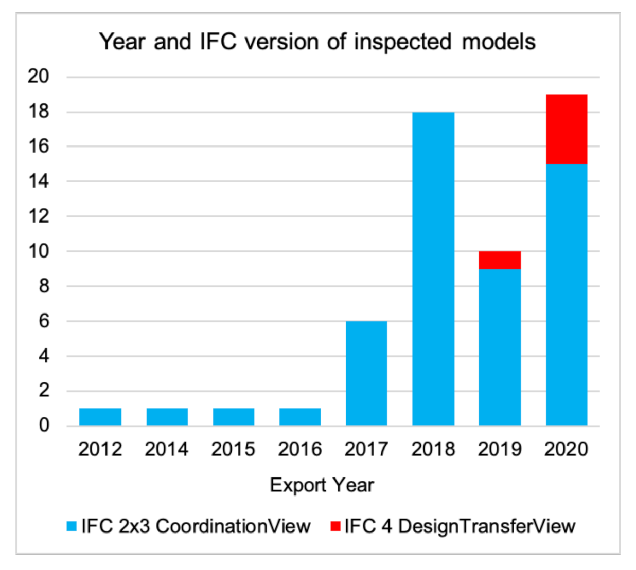
The models inspected were exported in the last 8 years: the oldest one was from 2012, when the IFC v.2x3 schema was already 5 years old, and one year before the first specification of IFC v.4 was officially published, in 2013. We can notice that most of the models were produced in the IFC version 2x3—Model View Definition CoordinationView 2.0, at least until 2020 (after 7 years from release), when some models were provided in IFC v.4—Model View Definition ’DesignTransfer View’ (the IFC4 model from 2019 was specifically requested by the authors for the needs of a different study, the ISPRS EuroSDR GeoBIM benchmark [48] in version 4) (Figure 2).
5.2. Modelling Software
Another formal aspect that influences the content and structure of IFC files and models is the software which is used for the modelling. In fact, the way the IFC file is written (such as header, order of IFC entities and so on) is typical of each software, although all are compliant to the IFC syntax.
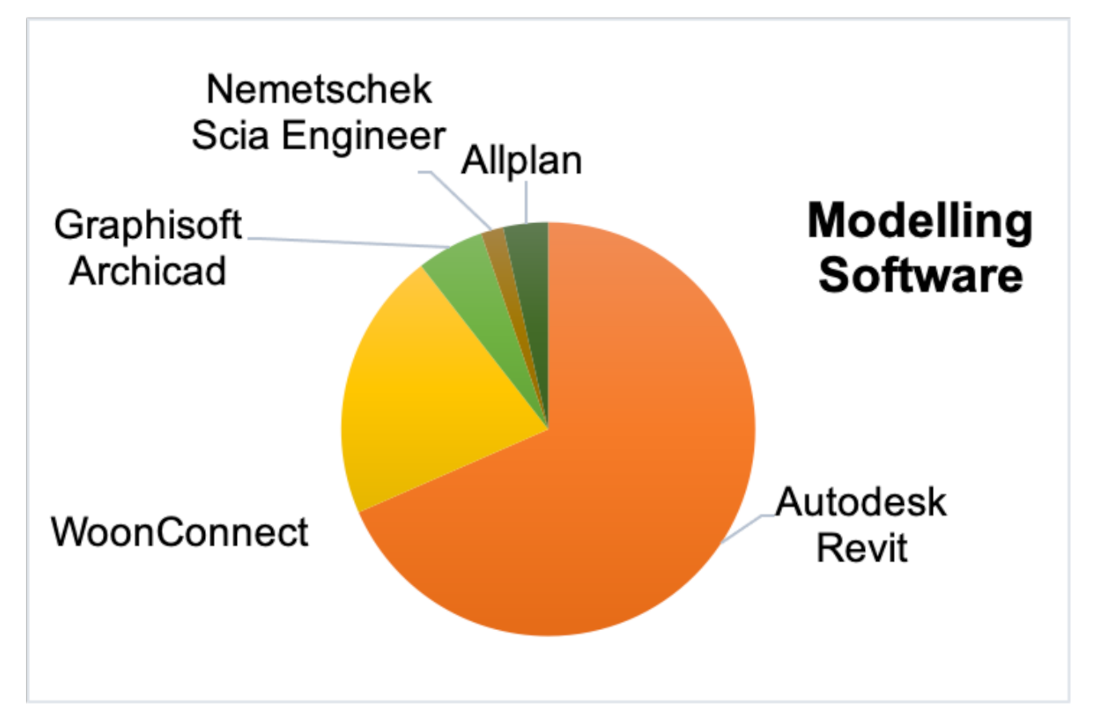
As it is apparent in Figure 3, Autodesk Revit was used for the most part of models. In the graph, WoonConnect (https://woonconnect.nl, accessed on 1 March 2021) was also used for a large part of models. However, it should be considered that those 11 BIMs (n. 16 to 27 in Table A1) were all part of the same project, and for this reason they had similar characters and employed this (otherwise quite unusual) software.
5.3. Georeferencing
The detailed results of the inspection with respect to georeferencing information is reported in Table 3.
We can notice that in most cases some georeferencing information was present (only in one case there was no information at all). However, in many cases the georeferencing information was misleading, because it was wrong. In 24 cases out of 57 the information about planar coordinates stored in the higher LoGeoRef available was completely wrong; often probably associated by the software using a default location in the US (close to Boston). In another seven cases, such information was highly approximated, as a random point in the country where the building was supposed to be built, or where it was designed. Since in most of cases those two correspond, it is not possible to say if it was mainly due to the used national version of the software (usually Revit) or to default metadata attached to models based on their planned location. In two models, the approximation arrived at the level of the city where the building was planned: probably, such information was provided by designers for energy-related assessments (an approximated latitude is sufficient to perform energy simulations), however it was not sufficient to support integration with further geoinformation.
The models presenting a sufficient accuracy in the georeferencing information to potentially allow the integration with geoinformation were only nine, out of which five also stored information in lower LoGeoRefs with a lower accuracy (random point in the country or wrong information).
In any case, it was apparent how there was no rule or best practice, at present, about how the georeferencing information must be stored and what criteria it must follow, and the road towards systematic and reliable georeferencing requires more attention. The LoGeoRef30 and higher allowed the storage of Cartesian coordinates and that is why they should be preferred when high accuracy is necessary. However, lower levels could also be useful, depending on use cases.
Finally, no model used the entities added to version 4 of IFC to store more specific georeferencing information.
Essential is the kind of storage used to be explicit and to give the user control on it, to produce models where information can actually be found exactly where expected. In fact, different tools using the IFC file would likely refer to specific kind of geoinformation as stored in a specific LoGeoRef.
It should be also noted that not all the disciplinary models belonging to the same federated BIM always had common georeferencing information. This is also what influenced the georeferencing information available in IFC files in a bad way.
Besides solving the technical issues, the increase of awareness of designers and modellers about the meaning and value of a correct georeferencing will be a critical, but not obvious, step.
5.4. Use of Semantics
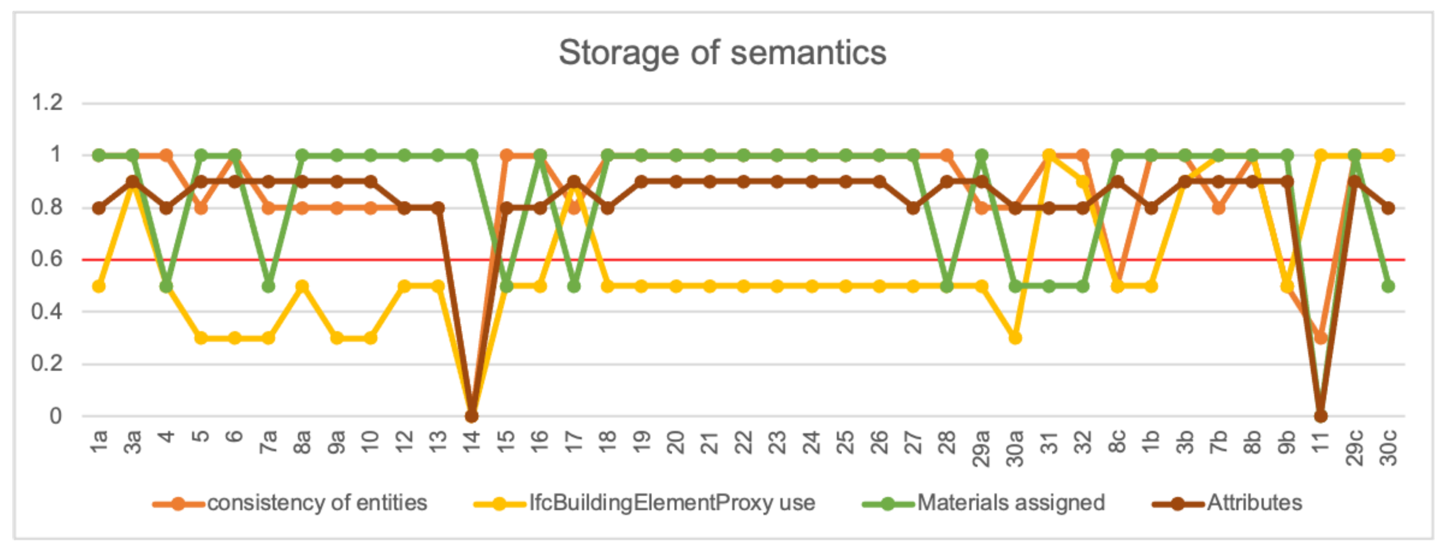
From the analysis of the semantics we can see that few models could be considered 100% consistent, although the information was stored with quite good care in many models. In Figure 4 the scores about consistency of entities, use of IfcBuildingElementProxy, storage of IfcMaterials and attributes are shown, according to the criteria explained in the methodology (Section 4.3.1). The numbers showed how very few models (only 3a, 3b, 7b, 8b) presented a sufficient score (higher than 0.6, red line in the graph) for all the aspects. Only those four had the higher chance to be successfully used within automatic processing.
Moreover, when looking at Figure 5, we saw that a high percentage of the IFC entities represented in the models presented high consistency, although the wrong use of IfcBuildingElementProxy even for only some objects could prevent a successful use of the model within automated tools.
In some cases, the entities were generally good, but a few elements presented serious errors, such as storing a slab within IfcWall, which would give serious problems to use the model by means of automatic tools and their quality was therefore considered not good.
In another case, IfcBuildingElementPart was used to store many elements, which was not incorrect, but the high level of abstraction made the models difficult to automatically interpret for many use cases.
The use of materials and attributes was hard to assess, since there are many different ways to store this in IFC: attributes are stored in the entity definition itself; also additional properties are defined within the standards, and a variable number of custom properties and attributes can be added.
IfcMaterial only had the attribute “Name” to be filled with IfcLabel. Therefore, no internationally shared classification was foreseen or recommended by IFC. This flexibility could be good to serve the needs of several users and contexts, but it went at the expense of interoperability for automatic use of such information.
In addition, many software tools could fill attributes and materials with default values. Therefore, it was very difficult to assess the reliability of such information, and it was only possible to give an approximated evaluation. For example we saw that IfcMaterial and related entities were filled somehow in most of the inspected models (33 out of 57 models), while they appeared as very inaccurate in 11 out of 57 models. For example, only the general name of the material was present (e.g., “concrete”) instead of the code of the material or a more extended description, which would make the information more useful. In only two models this information is not present at all.
Moreover, in one model, IfcMaterial entities were wrongly used to attach semantics, instead of storing objects by means of the correct entities.
Similarly, attributes could only be assessed subjectively based on their number: sometimes many attributes were there to describe entities and sometimes there were not. However, few cases used attributes from the IFC standard and therefore only few were completely consistent with IFC.
In many cases, the national languages, and sometimes national codelists, were used to identify and describe entities, especially concerning materials and attributes, but also to name or describe some classes. This is understandable due to efficiency reasons by practice (professionals needing easily understandable representations to support their tasks, which are often still quite manual). However, it is equally apparent how automatic processes from internationally shared tools could be hindered. The use of national language versions of codelists and terms should be improved, supported by tools and promoted among practitioners to use them directly within models and tools. Otherwise a mapping between the used terms and the standard ones is necessary to allow a consistent automatic use of the models. However, such descriptions usually do not come from national categories either, which means that any kind of automatic processing than a custom one would be supported.
5.5. Modelling
In this section the assessment of objects grouping (Section 5.5.1), representation of spaces (Section 5.5.2) and geometry (Section 5.5.3) are reported according to the criteria described in the methodology (Section 4.3.2).
5.5.1. Grouping of IfcSite, IfcBuilding, IfcStoreys
When looking at the grouping of objects, we can notice that the subclasses of IfcSpatialStructureElement (i.e., IfcSite, IfcBuilding and IfcBuildingStorey) in most cases were used similarly, probably due to the defaults export settings of software (mainly Autodesk Revit). It was a bit different for IfcSpace. However, their adoption was in all cases inaccurate: from the IFC specifications, they are not intended as a meronymic hierarchy (i.e., IfcBuildingStorey is part of an IfcBuilding, which in turn is part of an IfcSite), as they were instead wrongly used for the storage of entities (see Section 2.1).
IfcSite (https://standards.buildingsmart.org/IFC/RELEASE/IFC2x/ADD1/HTML/ifcproductextension/lexical/ifcsite.html, accessed on 1 March 2021), in 45 cases out of 57, included all the objects in the model, whatever they represented. In another six cases they included everything and in addition they were the class identifying the terrain represented in the model. Finally, in the remaining four models, besides being the group including all the other objects, it was used to classify the elements representing the context of the construction, outside the building, such as poles, external installation boxes, and road signs. In version 4 of IFC the entity IfcGeographicElement is introduced to represent such elements outside the building. However, in the models provided in IFC v.2x3 IfcSite is used for such an aim. Annotations are identified as IfcSite in one case. Moreover, in two cases, IfcSites group parts of the building, which could correspond to apartments in some cases, without full consistency both in the grouping and in the chosen semantics.
Looking at the use of IfcBuilding (https://standards.buildingsmart.org/IFC/RELEASE/IFC4_1/FINAL/HTML/schema/ifcproductextension/lexical/ifcbuilding.htm, accessed on 1 March 2021), 39 out of 57 models used the IfcBuilding class to group, correctly, all the elements belonging to one only building. However, IfcBuilding was used, probably as a default setting of the software, to group all the entities even in the cases where a building was not in the model (i.e., in four models representing a roundabout). It is true, though, that the roundabout was a designed construction and in IFC v.2x3 there are no specific entities to classify it. In another case of a model representing the context of a designed building, many buildings were represented as their envelope, and they were in turn equally grouped as only one building. Finally, in the sample there was the case of a building provided both as one model in its whole representation, and as the single segments (probably, the apartments), in other models, similar to the complete one regarding content.
In these cases, the two models of the whole buildings were segmented into parts (grouped as one building each). In addition, the single parts were provided as separated models (10 models), with each model labelled as one building In these cases, the grouping would be correct, although the attribute ’CompositionType’ should have the value ‘partial’, instead of ’element’, as actually was.
In the inspection of the IfcBuildingStoreys grouping we only considered the models representing buildings, since the ones of the roundabout did not present storeys to be represented. The model n.9c, representing the context, was not considered for this check either. There, IfcBuildingStoreys were used, inconsistently, to group the objects.
In the other cases, represented in Figure 6, only a small part of the models (only 4 out of 50) presented a good grouping of storeys, suitable to support automatic extraction of their bounding box. In this study, very detailed discrimination of the boundary elements between storeys was not considered to assess the grouping: for example, the separation of the slabs and the coverings as belonging to different storeys. It should however be defined in detail according to the specific use cases needs.
In some other cases (11 out of 50), only few inaccuracies were detected. They were not actual errors, though, but they were due to modelling needs (for example, elements which were included in only one storey but occupied more). A big slice of models instead presented errors in the assignment of elements to the correct storey, separated according to how serious the inaccuracies were. In some cases, the IfcBuildingStoreys were used to group a limited number of objects, which was not a correct use of such a class.
5.5.2. Spaces
The spaces were found to be modelled with many different features (Figure 7). In this case, only the 30 architectural models (without the facade one) were considered. 20% of them were well used to represent the volume enclosed by walls and other structures. In another 27% of cases the volumes were approximated and, for example, did not always follow the pitch of the roofs but were extruded boxes to a defined high. In addition, in 12 cases the IfcSpaceBoundaries are stored (representing the surfaces enclosing the volume of the space), but it was not a rule.
Bad representation of spaces included cases in which the representation of the spaces (and possibly their boundaries) appeared as displaced, with respect to the representation of the building elements, for some reason; in other cases, the IfcSpaces were well used, but only in a part of the model, while other models did not present IfcSpaces at all.
Finally, three models, all from the Netherlands (Rotterdam), although from different firms, presented an interesting, redundant modelling of overlapping spaces, including: the whole floor, parts of the floors (for example, only the part where it was possible to walk), the single apartments, the single rooms, the envelope of different volumes and representation of different surfaces (such as gross surface, net surface, gross or net volumes with respect to floors, ceilings or false ceilings), balconies and other similar parts.
In version 4 of IFC the class IfcZone was introduced to represent spaces independent from the physical elements enclosing them (for example, related to energy analysis). Instead, in these models, in version 2x3, the IfcSpace class was used to solve issues such as the computation of surfaces and volumes, the detection of apartments, together with the attachment of function (of both the single building units, such as residence, shops, etc., and of the single rooms). This information can be very relevant for many use cases, and at present it is tricky to be represented by means of the official prescriptions of the IFC model.
5.5.3. Geometry and Openings
It was only possible to visually inspect the very complex geometry, therefore, little detail and accuracy could be reached for this investigation.
However, it can be noticed how the models usually looked good, although some intersections were visible in at least 23 (almost half of the considered ones). Other observed errors included one case where shape irregularities were visible, as well as difficulties of some viewers (e.g., Solibri Model Viewer, FZK Viewer) to import and visualize three models, which presented geometries displacements and similar errors. The models being very big and very complex, it was difficult to provide a more accurate analysis without the use of systematic automatic tools (which do not exist).
It was also not very easy to accurately assess the use of IfcOpening class to model voids in geometries. However, they appeared to be well used in 27 cases out of 39 (almost 70%), while in other 12 models some irregularities (such as other objects are stored under this class) or partial use of such a class were detected.
From a visual inspection, apparent serious flaws were not visible. However, in order to use the models for automatic processing the observed errors should be avoided; the intersections generate issues [10] and a common practice needs to be followed for modelling.
5.6. Discussing Implications for Use Cases
The results showed that, at the present situation, the direct use of models for automatic processing is very difficult. Looking more specifically at some of the use cases, other than visualization and building design, as exemplified in Section 3, we notice that a very small number of the inspected models could be used directly as-they-were within automatic tools.
The accuracy of automatic calculation of building costs would be prevented for all but 5 models out of 39, for the combined quality of semantics (entities, attributes and use of IfcBuildingElementProxy) and materials (see Figure 4). Moreover, the low quality in geometry modelling and intersections would additionally affect this use case in at least 23 models out of the considered 57.
Semantic and geometric inaccuracies could prevent the use of most of models also for the structural analysis use case. Entities were represented with a sufficient consistency in 36 out of 39 models, although they were assessed as fully consistent in only 23 models. However, the wide use of the generic class IfcBuildingElementProxy in most of the models would make this information little usable anyway, and a manual check should still be necessary before going to any automatic processing. Materials (having sufficient representation in 30 out of 39 models) are also important to be added with their specific structural characteristics. Again, when considering all those semantic features together, no more than five models could be considered sufficient for automatic processing. Finally, grouping of elements was of importance: 15 out of 50 models reached the minimum score for IfcBuildingStoreys grouping.
For energy simulations, the materials were not properly specified in nine cases. The modelling of spaces was also important for this use case, but in 70% of models this information could not be properly used and in an additional 10% human editing was necessary to choose among the redundantly modelled spaces. At least an approximate georeferencing was necessary for this use case (minimum yellow in Table 3) for both planar coordinates and elevation. Only 10 models out of the whole sample had this property, without considering a minimum for the LoGeoRef, so that a LoGeoRef10 (the address) was also considered as a valid indication. Moreover, in half of the 10 cases, redundant but less accurate or wrong georeferencing information was stored according to different LoGeoRefs (see as example the models n.9 or 10 in Table 3). In those cases, human intervention would be necessary anyhow in order to select the correct alternative.
For urban planning, correctness of semantics (at least consistency of entities) was necessary, for which the same considerations applied as for the structural analysis use case. With respect to the grouping of storeys, 15 out of 50 models reached the minimum score about the use of IfcBuildingStorey; however, 11 out of them presented elements occupying more than one storey, although this was not a modelling error per se. In addition, the representation of spaces was important, for which the same comments as for the energy simulations use case applied and the quality of geometric modelling did not help: intersections and further irregularities could be noticed in at least half of the inspected models. Georeferencing in this case must be very accurate (green in Table 3) and store rotation as well. This means that only five models met the necessary requirement. An additional four could be considered in case they were modelled considering the correct orientation, but there was no way to check this. Additionally, in this case, all five models presented concurrent storage of wrong or less accurate information as different LoGeoRefs, that should probably be checked and adjusted manually.
The last considered use case was the conversion to other formats, especially requiring the change of used geometries and representation paradigm from solids representing single building elements (as most usual in BIM and IFC) to boundary surfaces representing envelopes of elements and spaces in different levels of generalization. This kind of conversion is required for many cases, such as the urban planning use case, 3D city models update and integration, energy simulations. For this case, the storage of geometries was of critical importance, yet, as reported for the previous cases, at least half of the models reported overlap and intersections. It is reasonable to assume that further inaccuracies such as small gaps and details in the geometry types and topology, little visible from a simple manual inspection, were most likely present in addition. Georeferencing and grouping were also very relevant (see the urban planning use case for both those features), as well and semantics. Sufficient semantics, considered as combined quality of entities, attributes and IfcBuildingElementProxy use, was in only 8 out the 39 models inspected, without looking at the quality of information about materials.
To conclude this analysis, it was possible to notice how for all the use cases no more than 5 to 10 models out of the whole sample could be directly used within automatic analysis without any further processing. Furthermore, this stands on the optimistic assumption that the same models met the higher quality criteria for the different considered aspects and that no further issues, which were hidden to a manual inspection procedure, as performed in this paper, existed.
Nonetheless, these considerations were done without the involvement of experts in the specific fields or using the specific software for each use case, for which the requirements could be even more restrictive.
6. Discussion
The results show, first of all, how models vary and do not present identical features in identical, expected ways. It would therefore be difficult to rely on the data content and structure of IFC files which is required when developing tools using the models as they are for automatic analysis and processing. This is partly due to the kind of implementation of IFC by modelling software, as it is possible to appreciate common aspects, such as default values or order of entities, in models exported from the same software.
However, it also happens because of the many alternatives allowed by the IFC data model to store similar objects and to use the schema for modelling data.
A further insight into this shows additional complexity: building models are conceived at a specific moment in the design and construction process and intended for a specific purpose. This can include the handover of information between stakeholders or for coordination. This purpose dictates the kind of information in the model, its level of development, but also the way it is encoded in the model. For example, for coordination, simple explicit geometries are preferred, but for exchange of design constraints more parametric procedural geometries are required. In earlier design stages walls might be schematic boxes, where in higher levels of development walls are decompositions with complex detailing at the joints. The subset of information and preferred encoding is formalized in a Model View Definition, which can be an internationally standardized one, local, or project-specific.
For the purpose of this research, there are two problems with this approach. First, the definition of MVDs is not a practice that is actually embedded in day to day construction projects. This makes the actual information content in a model rather implicit. Secondly, these model subsets are actually not formalized enough to the extent that they are computable. Conceptually, given a model constructed according to MVD A and a use case that requires MVD B, one could say one computes the intersection between A and B to see if these two are actually compatible. Or when a federated BIM consists of a model according to MVD C and MVD D one can compute the union between C and D to see how the two discipline models complement each other.
Such a formal approach is impeded by: (a) the somewhat weak semantics of mvdXML (the standard used to encode such subsets); (b) the fact that MVDs are easily incompatible due to the wide variety of somewhat equivalent constructs in the schema that MVD authors can select at will; and (c) the fact that in the MVD outline the model subsetting and specification of exchange requirements (a selection of property names for elements types) is interleaved. Considering those impediments and the fact that buildingSMART is transitioning away from mvdXML into a core interoperability layer of the schema with a simpler language for Information Delivery Specification, this research followed a more pragmatic approach.
However, the difficulty in mastering such a complex model and managing it within tools is a task for which many designers do not have resources to invest and which, at the moment, is not really attractive to them. It often also lies outside their area of interest because it supports the use of data downstream their own application. It would be therefore necessary to act on the simplification of the IFC model, the additional definition of constraints and on the increase of knowledge and awareness of designers about IFC and the need of producing interoperable (and standard) information, as well as about the advantages this implies. It is important to note that these improvements cannot all be expected to be solved by designers and BIM software vendors alone. First, requirements that are asked to be met by designers in order to yield more consistent IFC files should be reasonable for them to comply to. In addition, software should be ready and capable to meet the requirements more easily than current practice. Finally, tools should be developed to infer, enrich, validate and correct the data to enforce stricter standardization and better prepare the data for automated processing.
In the meantime, a careful check of the result of the export to IFC and the explication of the followed criteria in modelling, defining objects and filling attributes within clear metadata would help.
Once more, this study demonstrates how the collaboration between the different sectors of research, standardization, software developers, practitioners and stakeholders is relevant and how the development of standards and their aim to enforce consistent data to enable interoperability cannot be done in a successful manner without considering the implications for implementations.
7. Conclusions
In this research, we have analyzed the readiness of IFC data in practice to be used in automated process beyond the application for which the data was generated. This requires an unambiguous implementation of the standard that results in consistent data over various software implementations.
Although IFC can be very powerful in representing very detailed and complex information, this study points out that in the models, as they are produced in practice, not all the relevant standard-related aspects are always respected as they should be. This results in heterogeneous IFC solutions for similar situations which significantly hinders interoperability. In addition, some misalignments between different models and the standard schema can be detected, which can be due to the modelling practice, but also to the kind of implementation of IFC within software and to the related evidence that IFC standard flexibility allows several interpretations, which could be different, although not conflicting, for being format-compliant.
Moreover, for programming applications, it is also important to be aware of the most used software in modelling (e.g., Revit), that could imply, for example, specific kinds or patterns in modelling of geometries, semantics, georeferencing, or even just in the way the exported data are written.
The limitations of this study lie mainly in the dimension of the sample, which is 57 IFC models, divided in different disciplinary models, sometimes part of the same federated model or of the representations for a common projects. Moreover, 13 out of them represented installations, which are outside the main expertise of the authors and almost out of the scope of the inspection, although useful to assess some of the analyzed aspects additionally. The difficulty in finding more suitable models coming from practice was mainly due to privacy and copyright issues. However, even if the inspection in this research was carried out on a limited sample of models and by means of interactive procedures, it can clearly identify the traits which are common to most of them. Such points have to be ruled by means of guidelines (accompanied with supportive tools to meet such guidelines) or alternatively fixed by means of tools supporting the control of the models by the user. The awareness of modellers with respect to IFC is also a relevant step towards the production of highly standardized data.
In future research we will make advances on a more formal, computable approach to compatibility between use cases and models. Moreover, future efforts will be aimed to define and share good practices of BIM modeling that can foster interoperability, intended as the possibility to exchange and reuse the model effectively by different people and across different applications. Among these we can list: georeferencing; the use of IfcOpening and IfcSpaces; the consistent grouping of entities (e.g., in IfcBuildingStoreys); the correct and accurate filling of attributes, especially regarding materials, which are relevant in a number of applications, and the general assignment of entities. In addition, Information Delivery Specifications and formal MVDs will be considered as specific reference to automate the assessment and validation of the models for specific use cases. This step should be fulfilled in collaboration with both practitioners and software developers as well as stakeholders.
Author Contributions
Conceptualization, methodology, investigation F.N.; validation, K.A.O., T.K., J.S.; writing—original draft preparation, F.N.; writing—review and editing K.A.O., T.K., J.S.; funding acquisition, J.S., F.N. All authors have read and agreed to the published version of the manuscript.
Funding
This study has received funding from the European Union’s Horizon 2020 research and innovation programme under the Marie Skłodowska-Curie grant agreement no. 707404, project “Multisource spatial data integration for smart city applications”. This study has also received funding from the European Research Council (ERC) under the European Union’s Horizon2020 Research & Innovation Programme (grant agreement no. 677312 Urban modelling in higher dimensions).
Institutional Review Board Statement
Not applicable.
Informed Consent Statement
Not applicable.
Data Availability Statement
Data available on request due to privacy restrictions.
Acknowledgments
The models inspected for this paper were in-kindly provided by several institutions and architects, several of which collaborating in the EuroSDR GeoBIM project and in the ISPRS EuroSDR GeoBIM benchmark.
Conflicts of Interest
The authors declare no conflict of interest.
Appendix A
In Table A1 the complete description of the inspected data is reported.

Table A1.
Sample of models inspected.
| Country | Object | Scope | File Size | Instances | Products | Application | Schema | |
|---|---|---|---|---|---|---|---|---|
| 1a | NL (Almere) | Building | Architectural | 32.245 MB | 611,390 | 6558 | Autodesk Revit 2017 (ENU) | IFC2X3 |
| 1b | Structural | 4.773 MB | 73,805 | 1713 | Autodesk Revit 2017 (ENU) | IFC2X3 | ||
| 1c | Installations | 24.309 MB | 444,559 | 4317 | Autodesk Revit 2017 (ENU) | IFC2X3 | ||
| 1d | Installations | 224.189 MB | 3,986,803 | 27,227 | Autodesk Revit 2017 (ENU) | IFC2X3 | ||
| 2a | E (Barcelona) | Infrastructure (roundabout) | “Architectural” (axis, signals, drainage, containment) | 46.476 MB | 889,227 | 405 | Autodesk Revit 2018 (ESP) | IFC2X3 |
| 2b | “Structural” (road surface) | 9.997 MB | 191,246 | 165 | Autodesk Revit 2018 (ESP) | IFC2X3 | ||
| 2c | Installations | 3.637 MB | 63,271 | 953 | Autodesk Revit 2018 (ESP) | IFC2X3 | ||
| 2d | Topography | 0.539 MB | 11,884 | 2 | Autodesk Revit 2018 (ESP) | IFC2X3 | ||
| 2e | Survey reference | 0.930 MB | 17,285 | 7 | Autodesk Revit 2018 (ESP) | IFC2X3 | ||
| 2f | Elements for expropriation and heritage | 0.444 MB | 5734 | 173 | Autodesk Revit 2018 (ESP) | IFC2X3 | ||
| 3a | Building (metrostation) | Architectural | 37.253 MB | 665,291 | 1537 | Autodesk Revit 2018 (ENU) | IFC2X3 | |
| 3b | Structural | 18.999 MB | 269,863 | 2665 | Autodesk Revit 2018 (ENU) | IFC2X3 | ||
| 3c | Installations | 83.949 MB | 1,396,271 | 11,049 | Autodesk Revit 2018 (ENU) | IFC2X3 | ||
| 4 | NL (Den Haag) | Building (auditorium) | Architectural | 5.518 MB | 89,554 | 1848 | Autodesk Revit Architecture 2013 | IFC2X3 |
| 5 | Building | Architectural | 5.525 MB | 93,285 | 524 | Autodesk Revit 2014 (ENU) | IFC2X3 | |
| 6 | Building | Architectural | 23.817 MB | 441,862 | 2097 | Autodesk Revit 2014 (ENU) | IFC2X3 | |
| 7a | NL (Rotterdam) | Building (big tower) | Architectural | 252.748 MB | 3,645,860 | 46,614 | Autodesk Revit 2015 (ENU) | IFC2X3 |
| 7b | Structural | 16.620 MB | 265,422 | 2867 | Autodesk Revit 2015 (ENU) | IFC2X3 | ||
| 8a | Building (big tower) | Architectural | 105.241 MB | 1,557,694 | 35,304 | Autodesk Revit 2019 (ENU) | IFC2X3 | |
| 8b | Structural | 53.106 MB | 775,151 | 3286 | Autodesk Revit 2019 (ENU) | IFC2X3 | ||
| 8c | Facade | 46.928 MB | 769,615 | 13,038 | Autodesk Revit 2019 (ENU) | IFC2X3 | ||
| 9a | Building (big tower) | Architectural | 291.054 MB | 3,827,125 | 65,822 | Autodesk Revit 2018 (ENU) | IFC2X3 | |
| 9b | Structural | 77.993 MB | 1,177,187 | 12,706 | Autodesk Revit 2018 (ENU) | IFC2X3 | ||
| 9c | Context | 54.768 MB | 1,034,837 | 74 | Autodesk Revit 2018 (ENU) | IFC2X3 | ||
| 10 | Building (big tower) | Architectural | 333.035 MB | 5,640,498 | 85,579 | Autodesk Revit 2015 (ENU) | IFC2X3 | |
| 11 | Building | Structural | 1.368 MB | 26,082 | 1058 | Scia Engineer 15.2.131 | IFC2X3 | |
| 12 | F (Epône) | Building | Architectural | 11.389 MB | 194,769 | 1815 | Autodesk Revit 2017 (FRA) | IFC2X3 |
| 13 | SE (Falun) | Building | Architectural | 28.454 MB | 522,687 | 2091 | Autodesk Revit 2018 (ENU) | IFC2X3 |
| 14 | NL (Almere) | Building | Architectural | 30.229 MB | 574,435 | 1158 | ARCHICAD-64 21.0.0 | IFC2X3 |
| 15 | I (Savigliano) | Building | Architectural | 22.600 MB | 407,140 | 2939 | Autodesk Revit 2019 (ITA) | IFC4 |
| 16 | NL (Amsterdam) | Building | Architectural | 73.257 MB | 1,024,661 | 3438 | WoonConnect | IFC2X3 |
| 17 | Building | Architectural | 257.511 MB | 3,468,079 | 4523 | WoonConnect | IFC2X3 | |
| 18 | Building (project A) | Architectural | 8.462 MB | 119,915 | 450 | WoonConnect | IFC2X3 | |
| 19 | Building (project A) | Architectural | 6.824 MB | 97,664 | 295 | WoonConnect | IFC2X3 | |
| 20 | Building (project A) | Architectural | 7.147 MB | 101,707 | 303 | WoonConnect | IFC2X3 | |
| 21 | Building (project A) | Architectural | 7.137 MB | 101,991 | 303 | WoonConnect | IFC2X3 | |
| 22 | Building (project A) | Architectural | 8.131 MB | 115,575 | 385 | WoonConnect | IFC2X3 | |
| 23 | Building (project A) | Architectural | 7.405 MB | 106,676 | 406 | WoonConnect | IFC2X3 | |
| 24 | Building (project A) | Architectural | 6.600 MB | 94,884 | 316 | WoonConnect | IFC2X3 | |
| 25 | Building (project A) | Architectural | 6.495 MB | 93,775 | 296 | WoonConnect | IFC2X3 | |
| 26 | Building (project A) | Architectural | 7.583 MB | 108,423 | 374 | WoonConnect | IFC2X3 | |
| 27 | Building (project A) | Architectural | 7.182 MB | 102,684 | 322 | WoonConnect | IFC2X3 | |
| 28 | I | Building | Architectural | 15.812 MB | 267,583 | 1740 | Autodesk Revit 2019 (ENU) | IFC2X3 |
| 29a | Building | Architectural | 36.049 MB | 656,574 | 3207 | ARCHICAD IFC add-on version: 3003 ITA FULL 23.0.0 | IFC2X3 | |
| 29b | Installations | 8.312 MB | 147,350 | 2189 | Autodesk Revit 2020 (ITA) | IFC2X3 | ||
| 29c | Structural | 2.052 MB | 32,456 | 705 | Allplan 2020.0 | IFC4 | ||
| 29d | Installations | 62.034 MB | 1,127,187 | 1963 | Autodesk Revit 2020 (DEU) | IFC2X3 | ||
| 29e | Installations | 55.064 MB | 1,031,402 | 4214 | Autodesk Revit 2020 (DEU) | IFC2X3 | ||
| 29f | Installations | 5.783 MB | 105,296 | 1443 | Autodesk Revit 2020 (ITA) | IFC2X3 | ||
| 30a | Building | Architectural | 146.689 MB | 2,655,309 | 4147 | ARCHICAD IFC add-on version: 3003 GER FULL 23.0.0 | IFC2X3 | |
| 30b | Installations | 6.247 MB | 102,561 | 3301 | Autodesk Revit 2020 (ITA) | IFC2X3 | ||
| 30c | Structural | 2.749 MB | 43,389 | 913 | Allplan 2020.0 | IFC4 | ||
| 30d | Installations | 12.187 MB | 214,775 | 2 42 | Autodesk Revit 2020 (DEU) | IFC2X3 | ||
| 30e | Installations | 63.876 MB | 1,176,164 | 6081 | Autodesk Revit 2020 (DEU) | IFC2X3 | ||
| 30f | Installations | 8.005 MB | 146,075 | 2081 | Autodesk Revit 2020 (ITA) | IFC2X3 | ||
| 31 | Building | Architectural | 8.377 MB | 86,147 | 1485 | Autodesk Revit 2020 (ITA) | IFC4 | |
| 32 | Building | Architectural | 63.519 MB | 603,051 | 7731 | Autodesk Revit 2020 (ENG) | IFC4 |
References
- Ma, Z.; Ren, Y. Integrated application of BIM and GIS: An overview. Procedia Eng. 2017, 196, 1072–1079. [Google Scholar] [CrossRef]
- Fosu, R.; Suprabhas, K.; Rathore, Z.; Cory, C. Integration of Building Information Modeling (BIM) and Geographic Information Systems (GIS)—A literature review and future needs. In Proceedings of the 32nd CIB W78 Conference, Eindhoven, The Netherlands, 27–29 October 2015; pp. 27–29. [Google Scholar]
- Garramone, M.; Moretti, N.; Scaioni, M.; Ellul, C.; Re Cecconi, F.; Dejaco, M. BIM and GIS Integration for Infrastructure Asset Management: A Bibliometric Analysis. ISPRS Ann. Photogramm. Remote Sens. Spat. Inf. Sci. 2020, 6, 77–84. [Google Scholar] [CrossRef]
- Liu, X.; Wang, X.; Wright, G.; Cheng, J.C.; Li, X.; Liu, R. A state-of-the-art review on the integration of Building Information Modeling (BIM) and Geographic Information System (GIS). ISPRS Int. J. Geo-Inf. 2017, 6, 53. [Google Scholar] [CrossRef] [Green Version]
- Biljecki, F.; Lim, J.; Crawford, J.; Moraru, D.; Tauscher, H.; Konde, A.; Adouane, K.; Lawrence, S.; Janssen, P.; Stouffs, R. Extending CityGML for IFC-sourced 3D city models. Autom. Constr. 2021, 121, 103440. [Google Scholar] [CrossRef]
- Ellul, C.; Boyes, G.; Thomson, C.; Backes, D. Towards integrating BIM and GIS—An end-to-end example from point cloud to analysis. In Advances in 3D Geoinformation; Springer: Berlin/Heidelberg, Germany, 2017; pp. 495–512. [Google Scholar]
- Gilbert, T.; Barr, S.; James, P.; Morley, J.; Ji, Q. Software Systems Approach to Multi-Scale GIS-BIM Utility Infrastructure Network Integration and Resource Flow Simulation. ISPRS Int. J. Geo-Inf. 2018, 7, 310. [Google Scholar] [CrossRef] [Green Version]
- Noardo, F.; Ellul, C.C.; Harrie, L.; Overland, I.; Shariat, M.; Ohori, K.A.; Stoter, J. Opportunities and Challenges for GeoBIM in Europe: Developing a building permits use-case to raise awareness and examine technical interoperability challenges. J. Spat. Sci. 2019, 65, 209–233. [Google Scholar] [CrossRef]
- Kumar, K.; Labetski, A.; Ohori, K.A.; Ledoux, H.; Stoter, J. The LandInfra standard and its role in solving the BIM-GIS quagmire. Open Geospat. Data Softw. Stand. 2019, 4, 5. [Google Scholar] [CrossRef] [Green Version]
- Arroyo Ohori, K.; Diakité, A.; Krijnen, T.; Ledoux, H.; Stoter, J. Processing BIM and GIS Models in Practice: Experiences and Recommendations from a GeoBIM Project in The Netherlands. ISPRS Int. J. Geo-Inf. 2018, 7, 311. [Google Scholar] [CrossRef] [Green Version]
- Hijazi, I.H.; Krauth, T.; Donaubauer, A.; Kolbe, T. 3DCityDB4BIM: A System Architecture for Linking BIM Server and 3DCityDB for BIM-GIS-Integration. ISPRS Ann. Photogramm. Remote Sens. Spat. Inf. Sci. 2020, 5, 195–202. [Google Scholar] [CrossRef]
- Olsson, P.O.; Johansson, T.; Eriksson, H.; Lithen, T.; Bengtsson, L.H.; Axelsson, J.; Roos, U.; Neland, K.; Rydén, B.; Harrie, L. Unbroken Digital Data Flow In The Built Environment Process: A Case Study In Sweden. Int. Arch. Photogramm. Remote Sens. Spat. Inf. Sci. 2019, XLII-2/W13, 1347–1352. [Google Scholar] [CrossRef] [Green Version]
- Colucci, E.; De Ruvo, V.; Lingua, A.; Matrone, F.; Rizzo, G. HBIM-GIS integration: From IFC to cityGML standard for damaged cultural heritage in a multiscale 3D GIS. Appl. Sci. 2020, 10, 1356. [Google Scholar] [CrossRef] [Green Version]
- Huang, W.; Olsson, P.O.; Kanters, J.; Harrie, L. Reconciling City Models with Bim in Knowledge Graphs: A Feasibility Study of Data Integration for Solar Energy Simulation. ISPRS Ann. Photogramm. Remote Sens. Spat. Inf. Sci. 2020, 6, 93–99. [Google Scholar] [CrossRef]
- Sun, J.; Olsson, P.; Eriksson, H.; Harrie, L. Evaluating the geometric aspects of integrating BIM data into city models. J. Spat. Sci. 2020, 65, 235–255. [Google Scholar] [CrossRef] [Green Version]
- Aleksandrov, M.; Diakité, A.; Yan, J.; Li, W.; Zlatanova, S. Systems architecture for management of BIM, 3D GIS and sensors data. Isprs Ann. Photogramm. Remote Sens. Spat. Inf. Sci. 2019, 4, 3–10. [Google Scholar] [CrossRef] [Green Version]
- Kang, T.W.; Hong, C.H. A study on software architecture for effective BIM/GIS-based facility management data integration. Autom. Constr. 2015, 54, 25–38. [Google Scholar] [CrossRef]
- Shoieb, K.; Serror, M.H.; Marzouk, M. Web-Based Tool for Interoperability among Structural Analysis Applications. J. Constr. Eng. Manag. 2020, 146, 04020058. [Google Scholar] [CrossRef]
- Sibenik, G.; Kovacic, I. Assessment of model-based data exchange between architectural design and structural analysis. J. Build. Eng. 2020, 32, 101589. [Google Scholar] [CrossRef]
- Ohori, K.A.; Biljecki, F.; Diakité, A.; Krijnen, T.; Ledoux, H.; Stoter, J. Towards an integration of GIS and BIM data: What are the geometric and topological issues. ISPRS Ann. Photogramm. Remote Sens. Spat. Inf. Sci. 2017, 4, 1–8. [Google Scholar]
- Pazlar, T.; Turk, Ž. Interoperability in practice: Geometric data exchance using the IFC standard. J. Inf. Technol. Constr. (ITcon) 2008, 13, 362–380. [Google Scholar]
- Barbini, A.; Malacarne, G.; Massari, G.; Monizza, G.P.; Matt, D.T. BIM objects library for information exchange in public works: The use of proprietary and open formats. WIT Trans. Built Environ. 2019, 192, 269–280. [Google Scholar]
- Noardo, F.; Krijnen, T.; Ohori, K.A.; Biljecki, F.; Ellul, C.; Harrie, L.; Eriksson, H.; Polia, L.; Salheb, N.; Tauscher, H.; et al. Reference study of IFC software support: The GeoBIM benchmark 2019—Part I. Trans. GIS 2021. [Google Scholar] [CrossRef]
- Noardo, F.; Harrie, L.; Arroyo Ohori, K.; Biljecki, F.; Ellul, C.; Krijnen, T.; Eriksson, H.; Guler, D.; Hintz, D.; Jadidi, M.A.; et al. Tools for BIM-GIS Integration (IFC Georeferencing and Conversions): Results from the GeoBIM Benchmark 2019. ISPRS Int. J. Geo-Inf. 2020, 9, 502. [Google Scholar] [CrossRef]
- Choi, J.; Leite, F.; de Oliveira, D.P. BIM-based benchmarking for healthcare construction projects. Autom. Constr. 2020, 119, 103347. [Google Scholar] [CrossRef]
- Hamledari, H.; Rezazadeh Azar, E.; McCabe, B. IFC-based development of as-built and as-is BIMs using construction and facility inspection data: Site-to-BIM data transfer automation. J. Comput. Civ. Eng. 2018, 32, 04017075. [Google Scholar] [CrossRef]
- ISO. Industry Foundation Classes (IFC) for Data Sharing in the Construction and Facility Management Industries; International Organization for Standardization: Geneva, Switzerland, 2013. [Google Scholar]
- Jaud, Š.; Donaubauer, A.; Heunecke, O.; Borrmann, A. Georeferencing in the context of building information modelling. Autom. Constr. 2020, 118, 103211. [Google Scholar] [CrossRef]
- Uggla, G.; Horemuz, M. Geographic capabilities and limitations of Industry Foundation Classes. Autom. Constr. 2018, 96, 554–566. [Google Scholar] [CrossRef]
- Noardo, F.; Wu, T.; Ohori, K.A.; Krijnen, T.; Stoter, J. Investigating the automation of building permit checks through 3D GeoBIM information. arXiv 2020, arXiv:2011.03117. [Google Scholar]
- Clemen, C.; Görne, H. Level of Georeferencing (LoGeoRef) using IFC for BIM. J. Geod. 2019, 10, 15–20. [Google Scholar]
- ISO. Industrial Automation Systems and Integration-Product Data Representation and Exchange; International Organization for Standardization: Geneva, Switzerland, 2014. [Google Scholar]
- Van Berlo, L.; Beetz, J.; Bos, P.; Hendriks, H.; Van Tongeren, R. Collaborative engineering with IFC: New insights and technology. In 9th European Conference on Product and Process Modelling, Iceland; Routledge Taylor & Francis Group: London, UK, 2012; pp. 811–818. [Google Scholar]
- Krijnen, T.; Noardo, F.; Ohori, K.A.; Ledoux, H.; Stoter, J. Validation and Inference of Geometrical Relationships in IFC. In Proceedings of the 37th International Conference of CIB W78, Sao Paulo, Brazil, 18–20 August 2020. [Google Scholar]
- Wu, S.; Wood, G.; Ginige, K.; Jong, S.W. A technical review of BIM based cost estimating in UK quantity surveying practice, standards and tools. J. Inf. Technol. Constr. (ITCon) 2014, 19, 534–562. [Google Scholar]
- Ismail, N.A.A.; Idris, N.H.; Ramli, H.; Sahamir, S.R.; Rooshdi, R.R.R.M. Sustainable BIM-based cost estimating for quantity surveyors. Chem. Eng. Trans. 2018, 63, 235–240. [Google Scholar]
- Ren, R.; Zhang, J.; Dib, H.N. BIM interoperability for structural analysis. In Proceedings of the Construction Research Congress 2018: Construction Information Technology, New Orleans, LA, USA, 2–4 April 2018. [Google Scholar]
- Papadopoulos, N.A.; Sotelino, E.D.; Martha, L.F.; Nascimento, D.L.M.; Faria, P.S. Evaluation of integration between a BIM platform and a tool for structural analysis. Sist. Gestão 2017, 12, 108–116. [Google Scholar] [CrossRef] [Green Version]
- Giannakis, G.; Lilis, G.; Garcia, M.; Kontes, G.; Valmaseda, C.; Rovas, D. A methodology to automatically generate geometry inputs for energy performance simulation from IFC BIM models. In Proceedings of the 14th International Conference of IBPSA-Building Simulation 2015, BS 2015, Bozen-Bolzano, Italy, 4–6 February 2015; pp. 504–511. [Google Scholar]
- Ciribini, A.L.; Melchiori, M.; Tagliabue, L.C.; Ventura, S.M. Development of a BIM library for building energy retrofitting: Current workflows and a proposal for a recommender system. In Proceedings of the 2019 European Conference on Computing in Construction, Crete, Greece, 10–12 July 209; Volume 1, pp. 314–323, ISBN 978-1-910963-37-1. [CrossRef] [Green Version]
- Luttun, J.; Krijnen, T. An Approach for Data Extraction, Validation and Correction Using Geometrical Algorithms and Model View Definitions on Building Models. In International Conference on Computing in Civil and Building Engineering; Springer: Berlin/Heidelberg, Germany, 2020; pp. 529–543. [Google Scholar]
- Maile, T.; O’Donnell, J.; Bazjanac, V.; Rose, C. BIM-Geometry modelling guidelines for building energy performance simulation. In Proceedings of the BS2013: 13th Conference of International Building Performance Simulation Association, Chambéry, France, 26–28 August 2013; pp. 3242–3249. [Google Scholar]
- Noardo, F.; Malacarne, G.; Mastrolembo Ventura, S.; Tagliabue, L.; Ciribini, A.; Ellul, C.; Guler, D.; Harrie, L.; Senger, L.; Waha, A.; et al. Integrating Expertises and Ambitions for Data-Driven Digital Building Permits-the EUnet4DBP. Int. Arch. Photogramm. Remote Sens. Spat. Inf. Sci. 2020, 44, 103–110. [Google Scholar] [CrossRef]
- Kim, I.; Choi, J.; Teo, E.A.L.; Sun, H. Development of K-BIM e-Submission prototypical system for the openBIM-based building permit framework. J. Civ. Eng. Manag. 2020, 26, 744–756. [Google Scholar] [CrossRef]
- Temel, B.; Başağa, H. Investigation of IFC file format for BIM based automated code compliance checking. J. Constr. Eng. 2020, 3, 113–130. [Google Scholar] [CrossRef]
- Ponnewitz, J. Bim-based building permit procedures using decision making methods. In Proceedings of the 2017 Winter Simulation Conference (WSC), Las Vegas, NV, USA, 3–6 December 2017; pp. 4652–4653. [Google Scholar]
- Olsson, P.O.; Axelsson, J.; Hooper, M.; Harrie, L. Automation of building permission by integration of BIM and geospatial data. ISPRS Int. J. Geo-Inf. 2018, 7, 307. [Google Scholar] [CrossRef] [Green Version]
- Noardo, F.; Arroyo Ohori, K.; Biljecki, F.; Ellul, C.; Harrie, L.; Krijnen, T.; Stoter, J. GeoBIM Benchmark 2019: Design and Initial Results. ISPRS-Int. Arch. Photogramm. Remote Sens. Spat. Inf. Sci. 2019, 42, 1339–1346. [Google Scholar] [CrossRef] [Green Version]
Figure 1.
The four layers in which the Industry Foundation Classes are organized. Source: IFC4.1 specification.
Figure 1.
The four layers in which the Industry Foundation Classes are organized. Source: IFC4.1 specification.

Figure 2.
Distribution of the sample models per year and Industry Foundation Classes (IFC) version.

Figure 3.
Used Building Information Modelling pieces of software to design and export the models.

Figure 4.
Graph representing the scores assigned to the considered four semantics aspects. The red line indicates the 0.6 score, minimum requirement.
Figure 4.
Graph representing the scores assigned to the considered four semantics aspects. The red line indicates the 0.6 score, minimum requirement.

Figure 5.
Distribution of models according to the assigned score about the consistency of entities and use of IfcBuildingElementProxy.
Figure 5.
Distribution of models according to the assigned score about the consistency of entities and use of IfcBuildingElementProxy.

Figure 6.
Distribution of models according to the assigned scores about the quality of grouping in storeys.
Figure 6.
Distribution of models according to the assigned scores about the quality of grouping in storeys.

Figure 7.
Distribution of models according to the quality of IfcSpace use.

Table 1.
Synthesis of LoGeoRefs as defined by Clemen and Görne [31].
Table 1.
Synthesis of LoGeoRefs as defined by Clemen and Görne [31].
| LoGeoRef | Supported CRS | Storing Entities |
|---|---|---|
| LoGeoRef10 | No CRS, approximate location by means of the address. | IfcPostalAddress referenced by either IfcSite or IfcBuilding. |
| LoGeoRef20 | WGS84 EPSG:4326 | Attributes RefLatitude, RefLongitude, RefElevation within IfcSite |
| LoGeoRef30 | Any Cartesian CRS, including projected coordinates (CRS not specified in the file) | IfcCartesianPoint referenced within IfcSite (defining the projected coordinates of the model reference point); IfcDirection attribute of IfcSite. |
| LoGeoRef40 | Any Cartesian CRS, including projected coordinates (CRS not specified in the file) | Attribute WorldCoordinateSystem storing the coordinates of the reference point in any Cartesian CRS (including the projected ones) and direction TrueNorth. Both are stored within IfcGeometricRepresentationContext. |
| LoGeoRef50 | Specific projected CRS, specified by means of the EPSG code | IFC v.4 only . Coordinates of the reference point stored in IfcMapConversion using the attributes Eastings, Northings and OrthogonalHeight for global elevation. Rotation for the XY-plane stored using the attributes XAxisAbscissa and XAxisOrdinate. The coordinate reference system (CRS) used is specified by IfcProjectedCRS in the attribute Name by means of the proper EPSG code. |
1 Ad-hoc solution used by several tools. 2 Most official IFC2x3-way to store the reference system. 3 The IFC4 way of documenting the used CRS and other georeferencing parameters was proposed to be backported to property sets also for version 2x3 of IFC. (https://forums.buildingsmart.org/t/geolocation-standards-in-ifc2x3-and-ifc4/2329, accessed on 1 March 2021). This could enable the achievement of LoGeoRef50 even for IFC2x3 files.
Table 2.
Synthesis features of the models inspected.
| Country | Object | Scope | |
|---|---|---|---|
| 1a | NL (Almere) | Building | Architectural |
| 1b | Structural | ||
| 1c–1d | Installations | ||
| 2a | E (Barcelona) | Infrastructure (Roundabout) | Architectural (axis, signals, drainage, containment) |
| 2b | Structural (road surface) | ||
| 2c | Installations | ||
| 2d | Topography | ||
| 2e | Survey reference | ||
| 2f | Elements for expropriation and heritage | ||
| 3a | Building (metro station) | Architectural | |
| 3b | Structural | ||
| 3c | Installations | ||
| 4 | NL (Den Haag) | Building (auditorium) | Architectural |
| 5–6 | Building | Architectural | |
| 7a | NL (Rotterdam) | Building (big tower) | Architectural |
| 7b | Structural | ||
| 8a | Architectural | ||
| 8b | Structural | ||
| 8c | Facade | ||
| 9a | Architectural | ||
| 9b | Structural | ||
| 9c | Context | ||
| 10 | Architectural | ||
| 11 | Building | Structural | |
| 12 | F (Epône) | Building | Architectural |
| 13 | SE (Falun) | Building | Architectural |
| 14 | NL (Almere) | Building | Architectural |
| 15 | I (Savigliano) | Building | Architectural |
| 16–17 | NL (Amsterdam) | Building | Architectural |
| 18–27 | Building (project A) | Architectural | |
| 28 | I | Building | Architectural |
| 29a | Architectural | ||
| 29b | Installations | ||
| 29c | Structural | ||
| 29d–f | Installations | ||
| 30a | Architectural | ||
| 30b | Installations | ||
| 30c | Structural | ||
| 30d–f | Installations | ||
| 31 | Architectural | ||
| 32 | Architectural |
Table 3.
Kind and quality of georeferencing of the inspected models. The numbers refer to the corresponding LoGeoRef (with 0 as not georeferenced or using default values) and the colours refer to the accuracy of georeferencing: red = wrong; orange = approximation as a point in the same Country than the building; yellow = approximation as a point in the same city than the building; green = accurate location of the building in its actual location.
| Model | LoGeoRef North East | LoGeo Ref Elev. | Rotation | Notes | ||||||||||
|---|---|---|---|---|---|---|---|---|---|---|---|---|---|---|
| 0 | 10 | 20 | 30 | 40 | 0 | 20 | 30 | 40 | 0 | 20 | 30 | 40 | ||
| 1a | x | x | x | x | ||||||||||
| 1b | x | x | x | |||||||||||
| 1c | x | x | x | |||||||||||
| 1d | x | x | x | |||||||||||
| 2a | x | x | x | |||||||||||
| 2b | x | x | x | x | x | |||||||||
| 2c | x | x | x | |||||||||||
| 2d | x | x | x | x | x | Consistent with n.2b | ||||||||
| 2e | x | x | x | x | x | Consistent with n.2b | ||||||||
| 2f | x | x | x | x | x | Consistent with n.2b | ||||||||
| 3a | x | x | x | |||||||||||
| 3b | x | x | x | Consistent with 3a | ||||||||||
| 3c | x | x | x | Consistent with 3a | ||||||||||
| 4 | x | x | x | x | ||||||||||
| 5 | x | x | x | x | ||||||||||
| 6 | x | x | x | |||||||||||
| 7a | x | x | x | |||||||||||
| 7b | x | x | x | x | ||||||||||
| 8a | x | x | x | x | ||||||||||
| 8b | x | x | x | |||||||||||
| 8c | x | x | x | x | ||||||||||
| 9a | x | x | x | x | x | |||||||||
| 9b | x | x | x | x | x | x | Consistent with 9a | |||||||
| 9c | x | x | x | x | x | Consistent with 9a | ||||||||
| 10 | x | x | x | x | x | x | ||||||||
| 11 | x | x | x | |||||||||||
| 12 | x | x | x | x | ||||||||||
| 13 | x | x | x | x | x | |||||||||
| 14 | x | x | x | x | ||||||||||
| 15 | x | x | x | x | x | |||||||||
| 16 | x | x | x | |||||||||||
| 17 | x | x | x | x | ||||||||||
| 18 | x | x | x | |||||||||||
| 19 | x | x | x | |||||||||||
| 20 | x | x | x | |||||||||||
| 21 | x | x | x | |||||||||||
| 22 | x | x | x | |||||||||||
| 23 | x | x | x | x | ||||||||||
| 24 | x | x | x | |||||||||||
| 25 | x | x | x | |||||||||||
| 26 | x | x | x | |||||||||||
| 27 | x | x | x | |||||||||||
| 28 | x | x | x | x | ||||||||||
| 29a | x | x | x | |||||||||||
| 29b | x | x | x | x | ||||||||||
| 29c | x | x | x | |||||||||||
| 29d | x | x | x | x | ||||||||||
| 29e | x | x | x | x | ||||||||||
| 29f | x | x | x | x | ||||||||||
| 30a | x | x | x | |||||||||||
| 30b | x | x | x | x | ||||||||||
| 30c | x | x | x | |||||||||||
| 30d | x | x | x | x | x | |||||||||
| 30e | x | x | x | x | x | |||||||||
| 30f | x | x | x | x | ||||||||||
| 31 | x | x | x | x | ||||||||||
| 32 | x | x | x | |||||||||||
Publisher’s Note: MDPI stays neutral with regard to jurisdictional claims in published maps and institutional affiliations. |
© 2021 by the authors. Licensee MDPI, Basel, Switzerland. This article is an open access article distributed under the terms and conditions of the Creative Commons Attribution (CC BY) license (http://creativecommons.org/licenses/by/4.0/).
Share and Cite
MDPI and ACS Style
Noardo, F.; Arroyo Ohori, K.; Krijnen, T.; Stoter, J. An Inspection of IFC Models from Practice. Appl. Sci. 2021, 11, 2232. https://doi.org/10.3390/app11052232
AMA Style
Noardo F, Arroyo Ohori K, Krijnen T, Stoter J. An Inspection of IFC Models from Practice. Applied Sciences. 2021; 11(5):2232. https://doi.org/10.3390/app11052232
Chicago/Turabian StyleNoardo, Francesca, Ken Arroyo Ohori, Thomas Krijnen, and Jantien Stoter. 2021. "An Inspection of IFC Models from Practice" Applied Sciences 11, no. 5: 2232. https://doi.org/10.3390/app11052232
Note that from the first issue of 2016, this journal uses article numbers instead of page numbers. See further details here.