Article

Around-View-Monitoring-Based Automatic Parking System Using Parking Line Detection

1
Litbig, Seongnam-Si 13487, Korea
2
Department of Electronic Engineering, College of Convergence Technology, Korea National University of Transportation, Chungju-Si 27469, Korea
*
Author to whom correspondence should be addressed.
Appl. Sci. 2021, 11(24), 11905; https://doi.org/10.3390/app112411905
Submission received: 8 November 2021 / Revised: 30 November 2021 / Accepted: 9 December 2021 / Published: 14 December 2021
(This article belongs to the Topic Intelligent Transportation Systems)

Abstract

:
This paper introduces an automatic parking method using an around view monitoring system. In this method, parking lines are extracted from the camera images, and a route to a targeted parking slot is created. The vehicle then tracks this route to park. The proposed method extracts lines from images using a line filter and a Hough transform, and it uses a convolutional neural network to robustly extract parking lines from the environment. In addition, a parking path consisting of curved and straight sections is created and used to control the vehicle. Perpendicular, angle, and parallel parking paths can be created; however, parking control is applied according to the shape of each parking slot. The results of our experiments confirm that the proposed method has an average offset of 10.3 cm and an average heading angle error of 0 . 94 .

1. Introduction

Recently, as the number of vehicles has increased, the automobile industry has expanded its research and development; for instance, driver assistance systems are being studied intensively. Driver assistance systems consist of lane departure warning, forward collision warning, pedestrian protection, and parking assist systems [1,2]. The parking assist system assists the driver in parking situations so that they can park easily. These systems have continuously increased in sophistication from collision warning systems using an ultrasonic sensor [3,4] to systems that show a rear image to the driver using a rear camera, systems that provide a 360 -view using an around view monitoring (AVM) camera [5,6,7], and fully automatic parking systems [5].
This paper presents an automatic parking system that uses AVM images in a driver assistance system. An AVM system consists of cameras on the front, rear, left, and right sides of the vehicle and shows a 360 -camera view of the vehicle’s environment. In particular, it shows the driver a synthesized image of the top view of the vehicle. Because the AVM system provides a top view, it can be used for various applications involving image recognition such as lane detection, moving object detection, and parking line detection. These systems can use the original images from the cameras, but such an approach requires extensive computation time because four images must be processed. By contrast, if a synthesized top view image is used, the processing time of only one image is required. Therefore, in this paper, we propose an automatic parking method that detects parking lines and performs parking control using a top view image.
Parking line recognition is an important process in an automatic parking system. Using the detected parking lines, a system can be configured to automatically park the car in the area desired by the driver. When parking lines are detected in the top view AVM image, the position of each pixel can be converted into a distance, which is advantageous for automatic parking. In addition, all parking lines in each direction can be detected. The detected parking lines provide relative coordinates because it is easy to convert pixels into distances from the vehicle. Hence, we use these relative coordinates to set a goal to the desired parking location and perform automatic parking using path planning and tracking methods.
Figure 1 presents an overview of the proposed method.
As shown in the figure, when an AVM image is input to the system, the parking lines are detected. The proposed system determines the parking area from the detected parking lines. It also determines the relative location of the car to the parking area and the shape of the parking area. Path planning is performed using this information, and automatic parking is performed through path tracking.
The rest of this paper is organized as follows. Related studies on the detection of parking areas and automatic parking control are summarized in Section 2. Section 3 presents the proposed method. Section 4 presents the experimental results, and the paper is concluded in Section 5.

2. Related Works

Automatic parking systems using AVM images can be divided into a parking slot detection part and a path planning and tracking part.
Various studies have been conducted on the detection of parking slots using AVM-based systems. To recognize parking lines, a commonly used method involves locating a corner point through line recognition and determining whether or not that corner is part of a parking dividing line. For instance, parking lines have been detected in AVM images using the Hough transform [8]; a top hat filter and directional DBSCAN [9]; Canny edge detection and the Radon transform [10]; local symmetry of brightness and a Dirac comb [11]; the Sobel filter, RANSAC, and edge pairs [12]; FAST corner detection and RANSAC [13]; and a probabilistic occupancy filter [14]. Moreover, Zhang et al. detected the corners of parking lines and parking slots using gradient values, AdaBoost, and decision trees [15]. Kim et al. recognized parking slots by detecting lines and junctions [16], and parking slots have also been detected using a semantic segmentation filter and a convolutional neural network (CNN) [17]. Zhang et al. recognized parking areas using a deep CNN [18]. Partially occluded parking lines were recognized by Allodi et al. using segment labeling [19] and by Lee et al. using line features and feature clustering in the top view image [20].
Furthermore, various studies have been conducted on path planning and tracking. Zips et al. defined perpendicular, angle, and parallel parking modes, and created parking paths using a fast motion planning algorithm [21]. Subsequently, they created optimized paths that can be used for narrow spaces [22]. Lin et al. defined perpendicular parking and parallel parking modes and created parking paths using a four-phase algorithm [23]. Sedighi et al. and Kim et al. generated paths for perpendicular parking using a clothoid-based method [24,25]. Vorobieva et al. created a parallel parking path using clothoids and performed parking control using an actual vehicle [26]. Wang created circular trajectories using the parking lines recognized by the AVM system and performed automatic parking with a test vehicle [10]. Li et al. created paths for perpendicular parking and parallel parking using fuzzy control and performed parking control using a mobile robot [27]. Parking paths have been created using collision-free and nonholonomic paths generated by the slice projection technique [28] and a method that considers the surrounding environment and generates an optimal path by dividing the motion of a car into translation and rotation motions [29].
The proposed method uses the Hough transform to detect lines and cross points. Using the Hough transform has the advantage of detecting straight lines and cross points with simple operations. On the other hand, there is a disadvantage that it is difficult to distinguish the parking line from other lines. Therefore, the proposed method uses CNN to distinguish cross points with high accuracy. Furthermore, the proposed method uses circles and lines for path planning. Although this method has the disadvantage of taking a long time to control the vehicle, it has the advantage of being suitable for application to an actual vehicle and controlling the vehicle with high accuracy. Therefore, the proposed method uses a method using a circle and a line that is suitable for high accuracy and real automobile applications.

3. Proposed Method

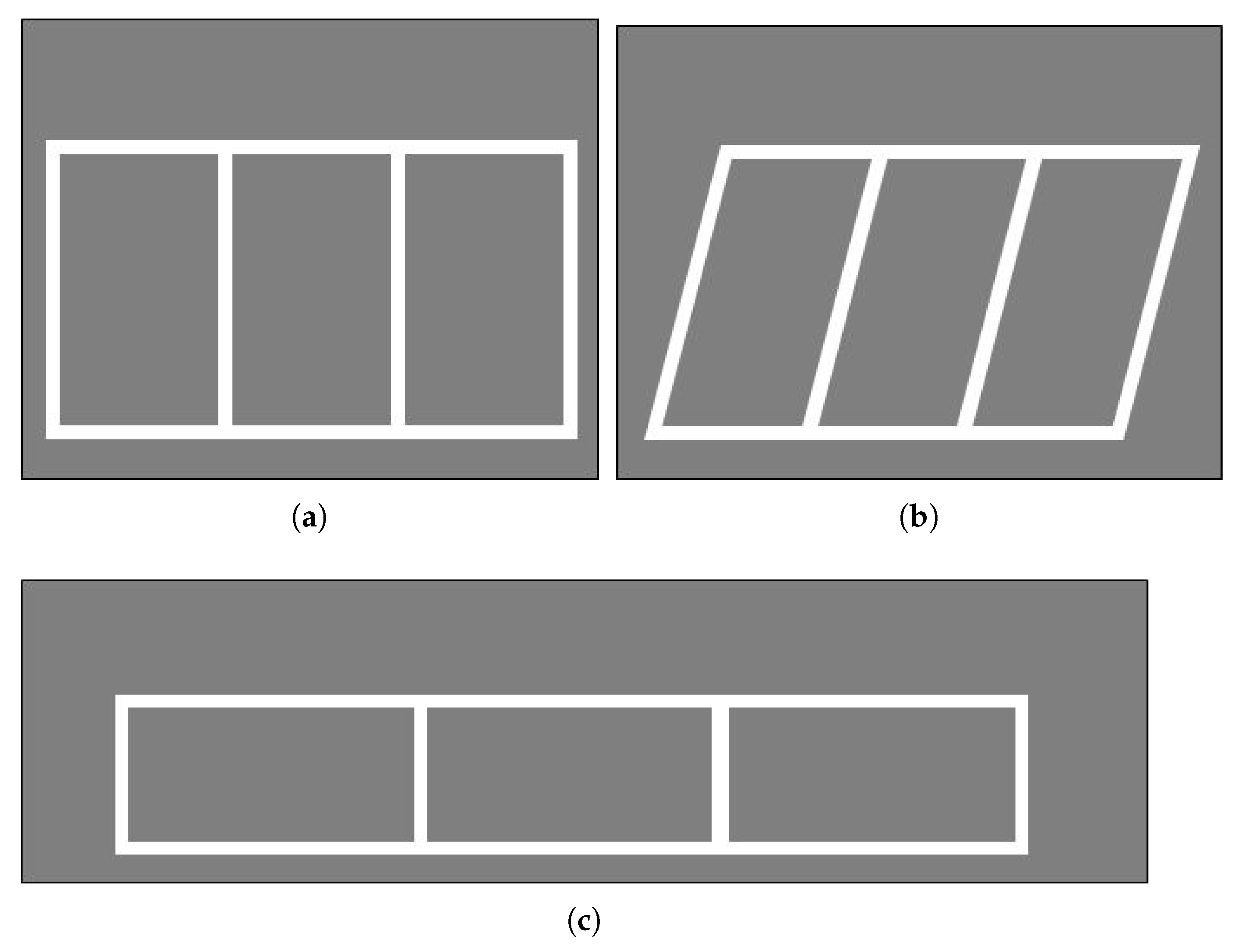
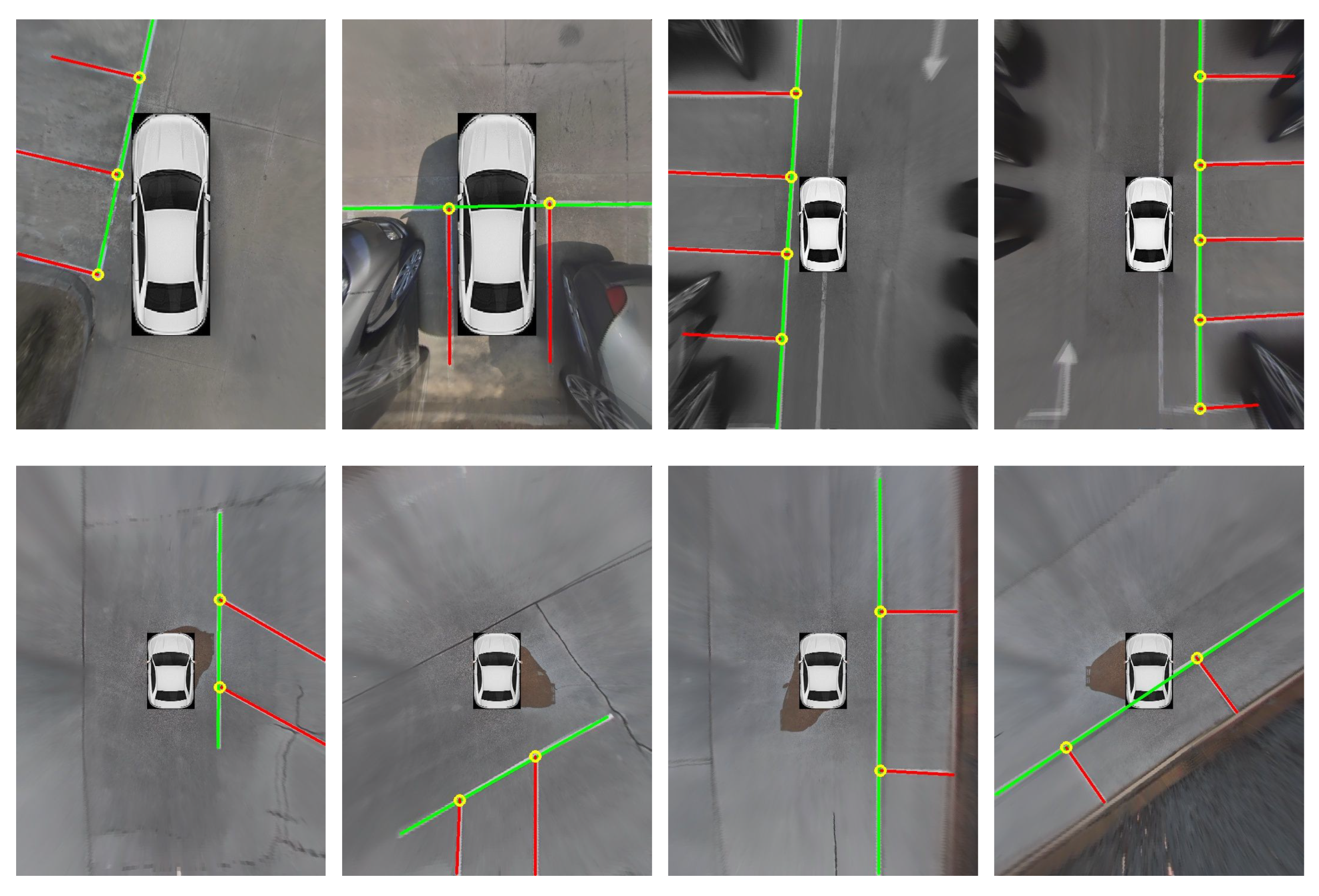
3.1. Parking Line Detection

We propose a method for recognizing parking lines in AVM images. To detect parking lines, straight lines are extracted using the Hough transform. To check whether a corner on an extracted straight line is a parking line, a CNN, which is a deep learning method, is used to distinguish the corner points of the parking lines and other line components.

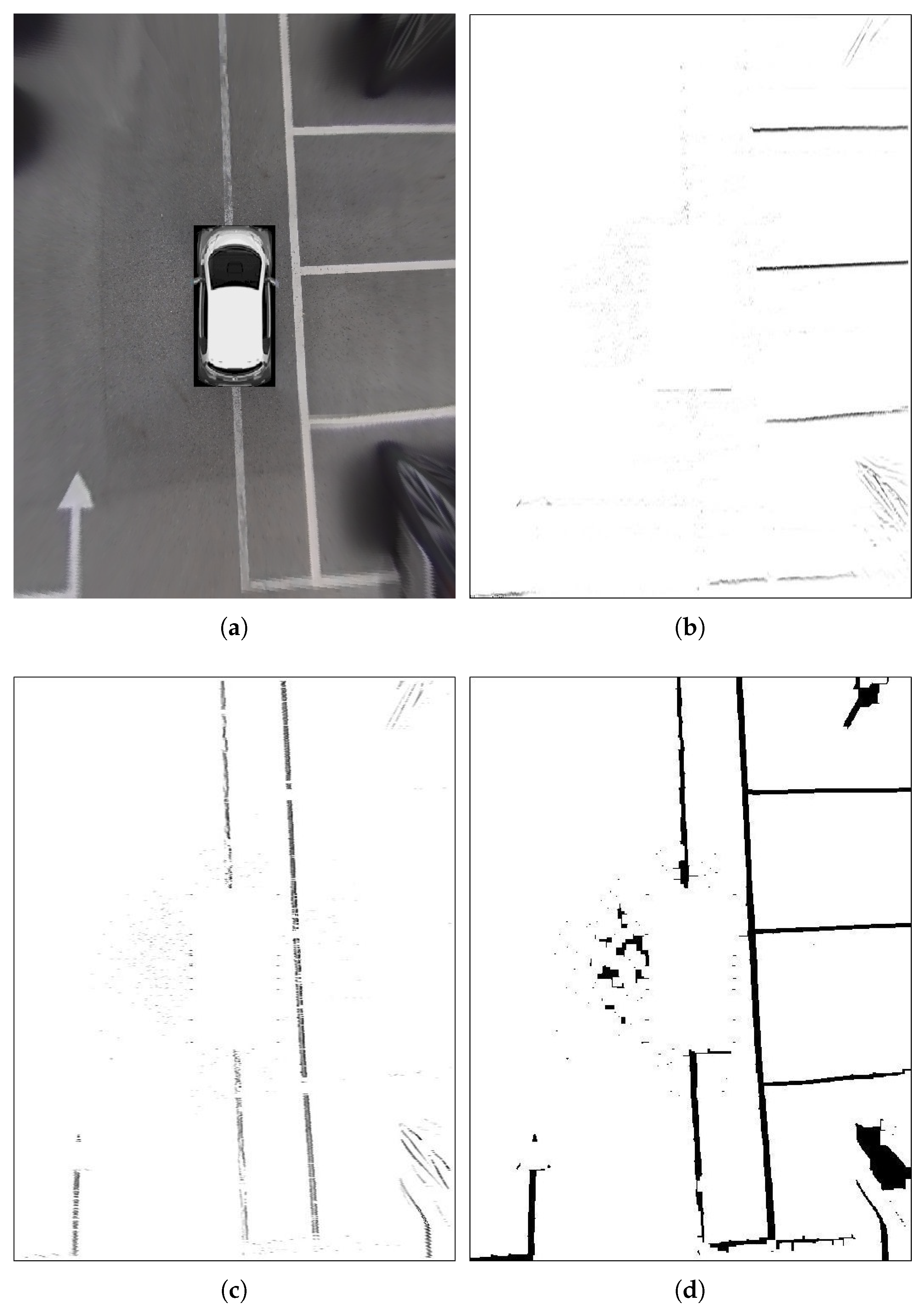
3.1.1. Parking Line Candidate Extraction Using the Hough Transform

To find parking lines in an AVM image, it is better to extract the parking lines from the image converted to the top view [7]. Because the converted image provides the viewpoint looking down from above, it is more suitable than the original images from the cameras. In particular, in the top view image, the parking lines are straight lines, and a position in the top view image can be displayed as a relative distance from the vehicle. Therefore, in the proposed method, parking lines are detected from the top view.
In top view images, the parking lines form rectangular shapes. Therefore, in a top view image, if there is a section where a vehicle can be parked, straight lines appear around its edges. To use this feature, parking lines are detected by locating the positions where straight lines intersect the rectangle [16].
To detect a straight line, the linear components are first extracted from the AVM image using a line filter. This enables robust performance in various environments; for instance, weather and lighting conditions can vary in underground parking slots or outdoors [9].
The mask of the line filter is depicted in Figure 2. This mask shape is used to filter the image in the x and y directions. In addition, because a parking dividing line has a rectangular shape, this filter is able to detect a parking line from any direction.
Lines with a certain width are distinguished by the filter. In the top view image, the width of a parking line is the same regardless of its distance from the vehicle. Therefore, the image can be filtered without changing the width of the line filter according to the distance. Figure 3 shows the result of finding features using a line filter. Figure 3a shows the AVM image; Figure 3b shows the vertical line filter result; Figure 3c shows the horizontal line filter result; and Figure 3d shows the result of combining the vertical and horizontal line filter results.
Linear components can be distinguished using the features found using the line filter. The proposed method obtains straight lines using the Hough transform, which represents a straight line using parameters rho and theta through a coordinate system transformation [8] as follows:
r = x cos θ + y sin θ .
As shown in Equation (1), ( x , y ) represents the position of a point in the image, ( r , θ ) represents the angle formed by a straight line with the distance from the origin. In Equation (1), a line is expressed as a straight-line component having a distance and an angle. Therefore, it is possible to detect the linear components formed by the most points.
Parking lines are straight lines because it helps make parking easier for drivers. Accordingly, there are corners in the parking lines on the left and right, and the parking line can be determined using these corners. They play an important role in finding parking lines. Figure 4 shows an example of the corner detection of an image. Figure 4a shows the Hough transform results and Figure 4b shows the corner detection results.

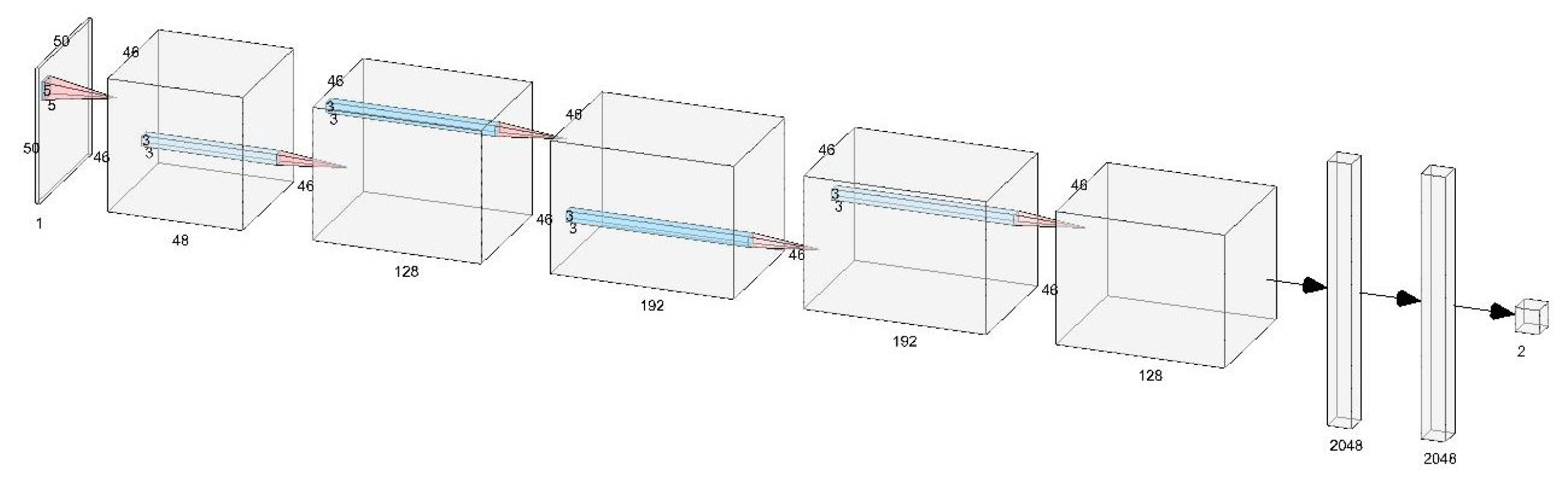
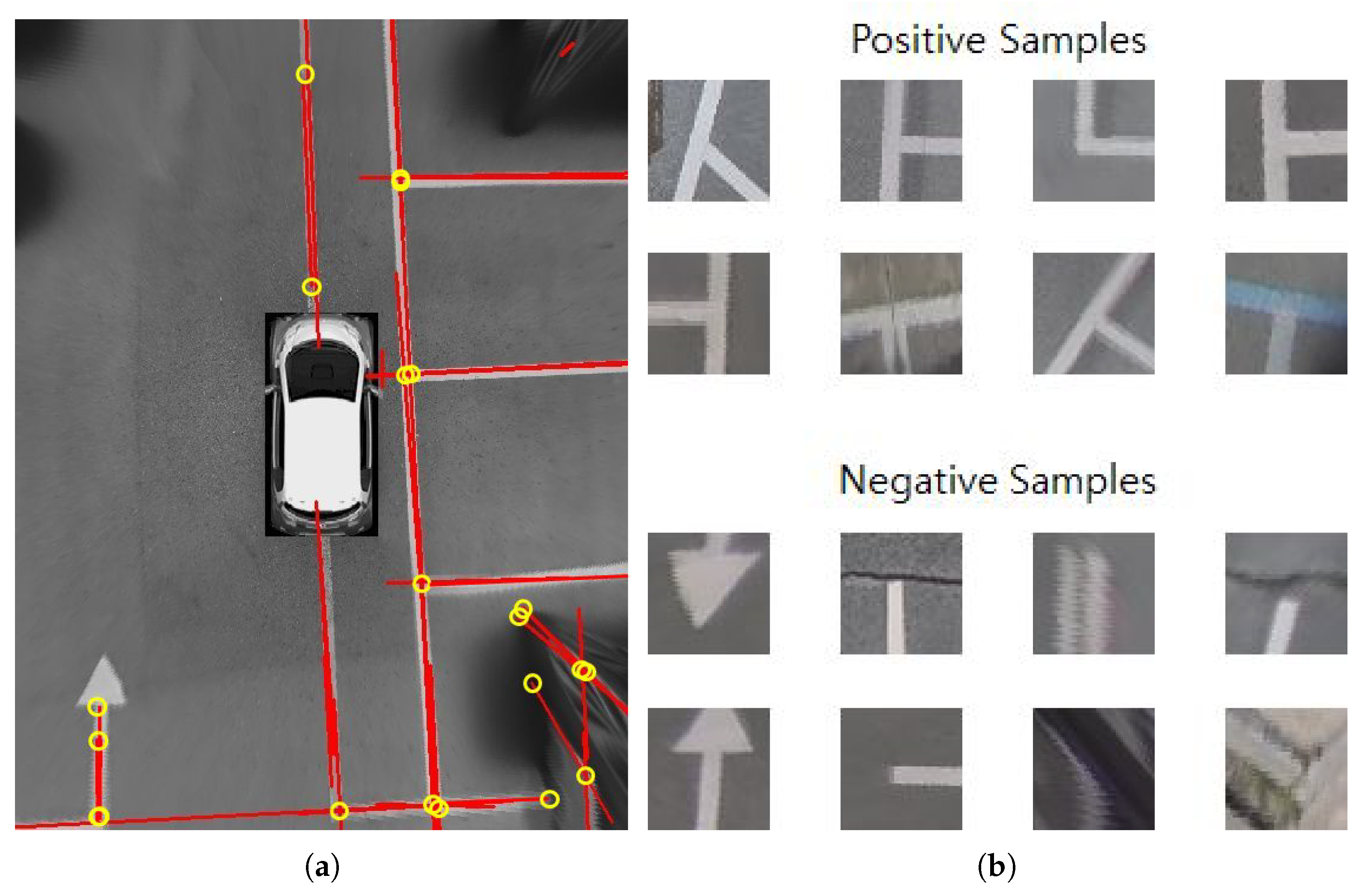
3.1.2. Parking Line Detection Using a CNN

For each detected parking corner, a CNN is used to determine whether or not it was a corner point of a parking line [18,30]. There are various models of CNNs, and there are many models that perform well, such as AlexNet [30], ZFNet [31], VGGnet [32], and GoogLeNet [33]. Because the proposed method must perform automatic parking in real time, a simple real-time model is best. Therefore, because simple operation is more important than a complex model, a modified form of LeNet [34] was used.
Figure 5 shows the CNN model used in the proposed method. It consists of six convolutional layers and two fully connected layers.
To train the CNN model, each corner point and non-corner point in the training images was classified and used for training. Figure 6 shows the examples of data used for learning.

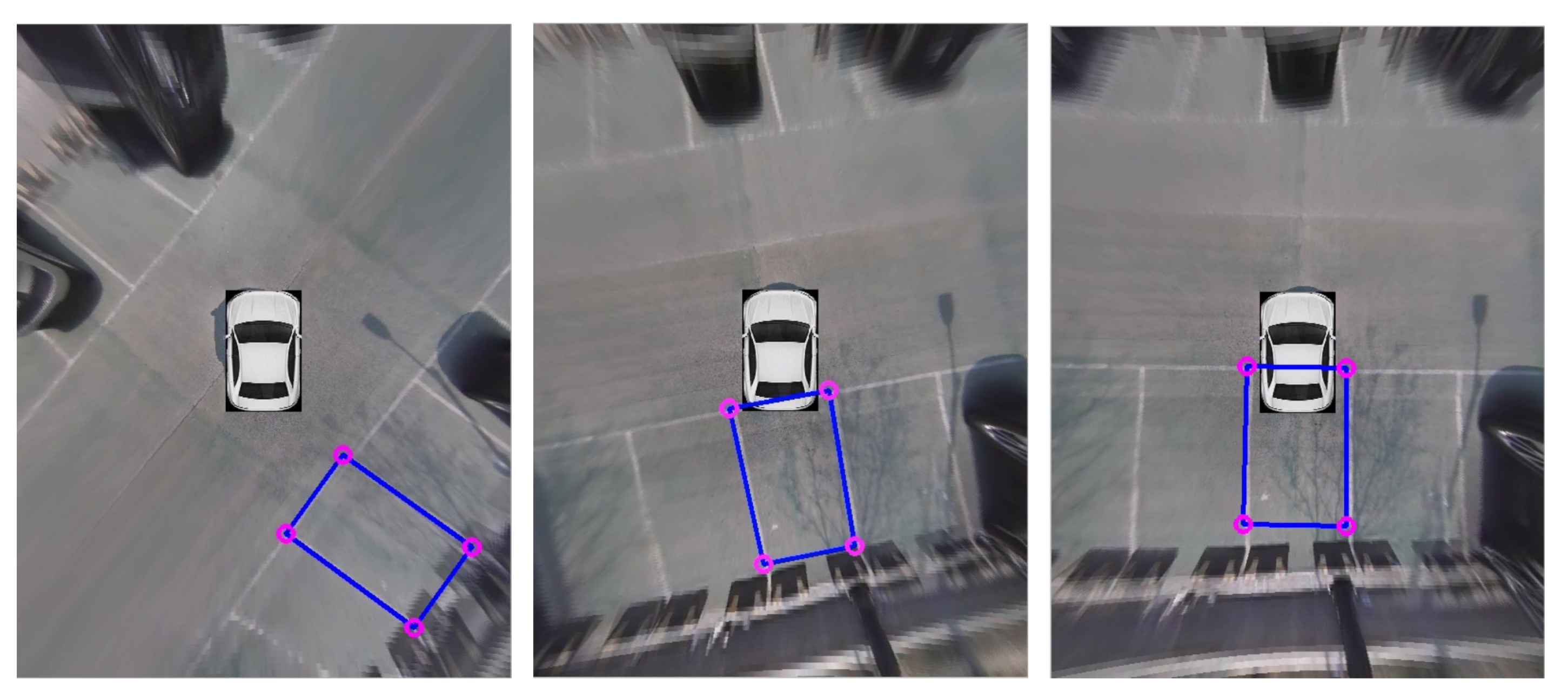
3.1.3. Parking Slot Tracking

After recognizing a parking slot, the parking location is determined and parking is performed. The parking slot is selected by the driver. Automatic parking is performed through path planning and tracking. During automatic parking, the vehicle moves and inevitably occludes the parking lines. In particular, there are cases where the corners and parking lines, which are important in this study, are not visible. As Figure 7 shows, during parking, the parking line may not be recognized in various circumstances, such as when a parking line or corner point is occluded. This highlights the importance of tracking the parking slot while parking to ensure proper parking control. Therefore, the approach proposed in this paper uses a method to track the parking slot so that the parking location information cannot be lost even while parking is in progress [35].
Therefore, the proposed method tracks the parking slot and is configured to provide information about the parking slot even when it is not covered or recognized during parking. For this, an algorithm to track the parking slot was employed.
To track the parking area, both corners of the parking area and the distance between them are used. The corners are tracked using a Kalman filter. The state matrix of the Kalman filter is as follows.
x = [ L x L y R x R y Δ L x Δ L y Δ R x Δ R y ] .
In Equation (2), L x and L y are the coordinates of the left corner of the parking area, Δ L x , Δ L y represent the derivative at the left corner coordinates, R x and R y are the coordinates of the right corner, and Δ R x and Δ R y represent the derivative at the right corner. In addition, because the distance between both points is fixed, this condition is used for tracking. When one point is occluded, the location and distance to the other point is used for tracking.
It is important to maintain the information about the parking area for vehicle control during actual automatic parking. Figure 8 shows how this is achieved. As shown, as parking proceeds, the parking line is almost completely occluded, but the parking line is detected because of the tracking algorithm.

3.2. Motion Planning and Tracking

Automatic parking is divided into three types: perpendicular, angle, and parallel parking. In this paper, we consider three types of parking and describe how automatic parking is performed using other methods and the results of parking slot detection.

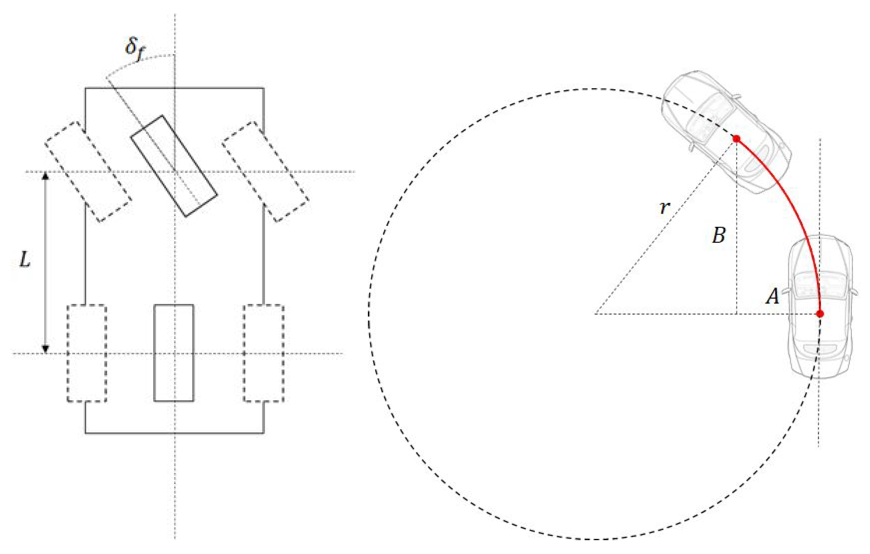
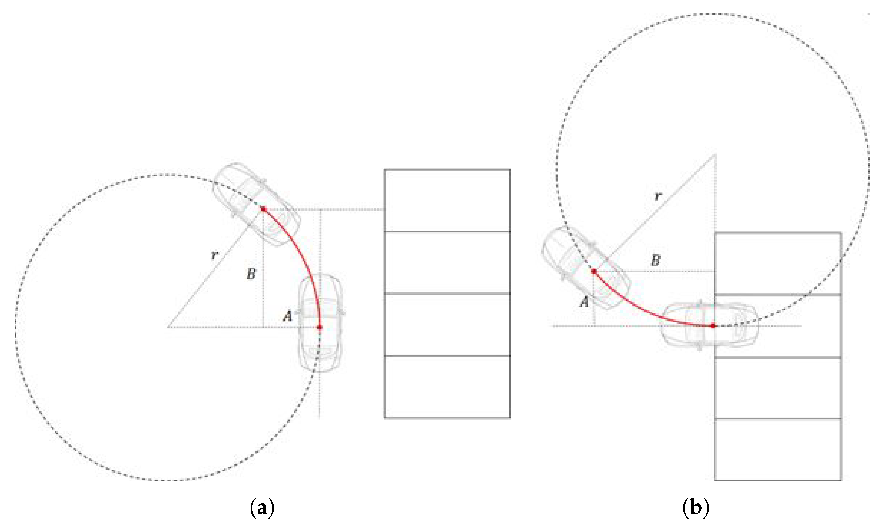
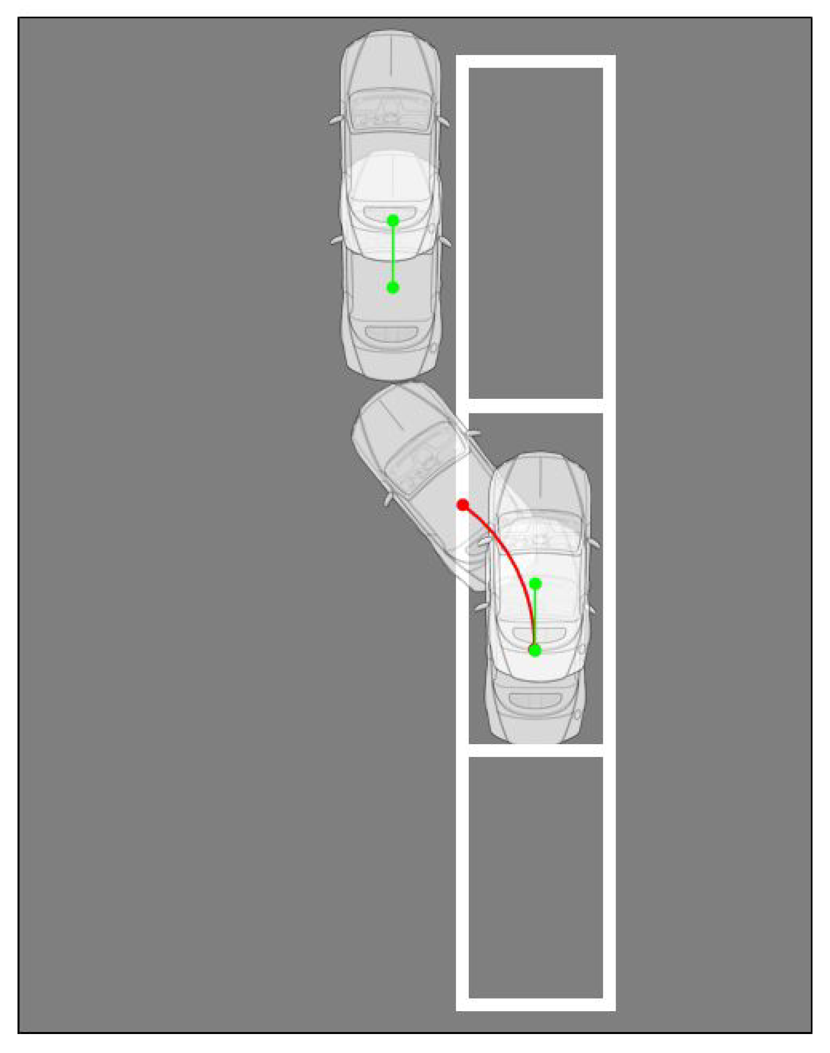
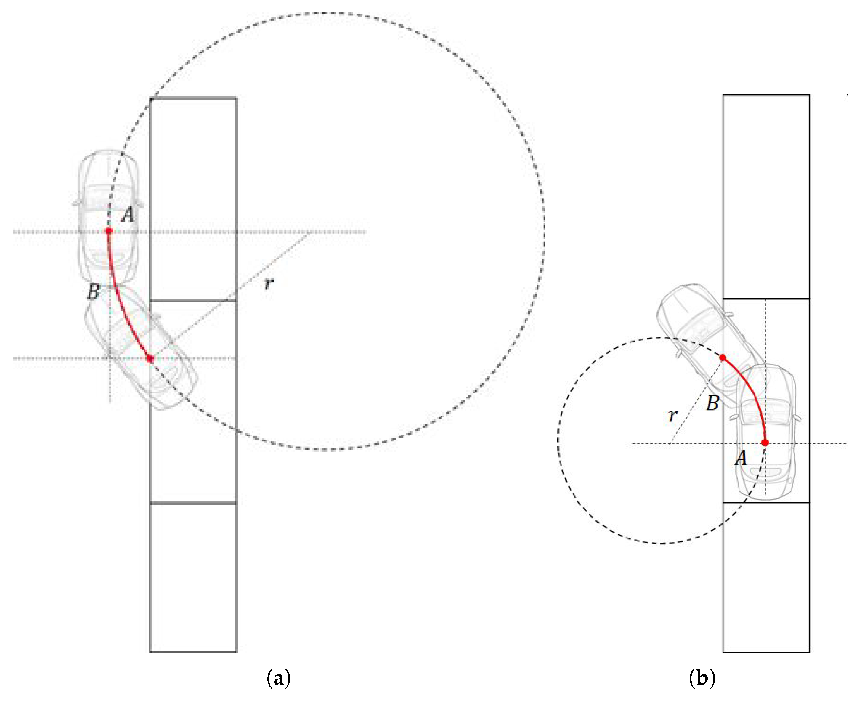
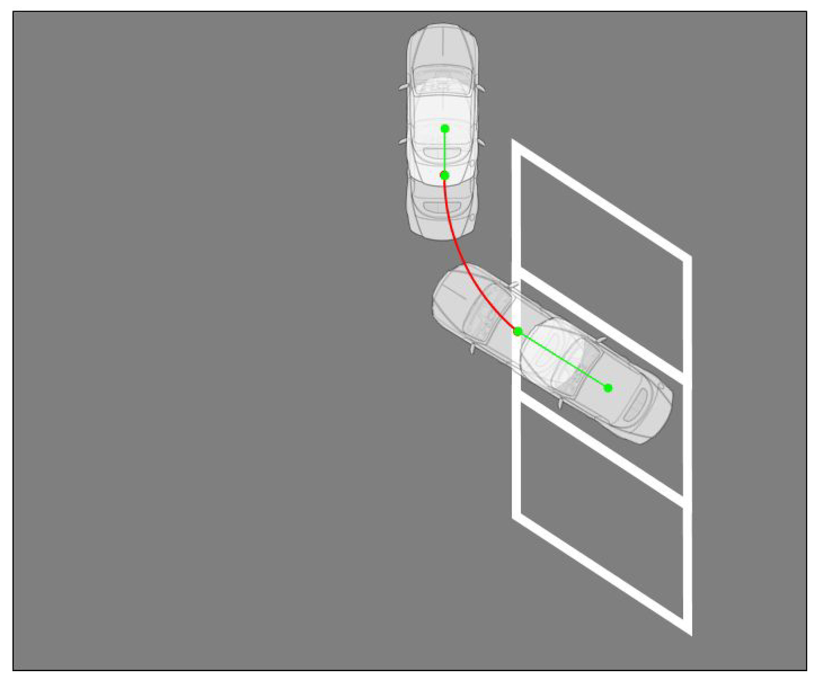
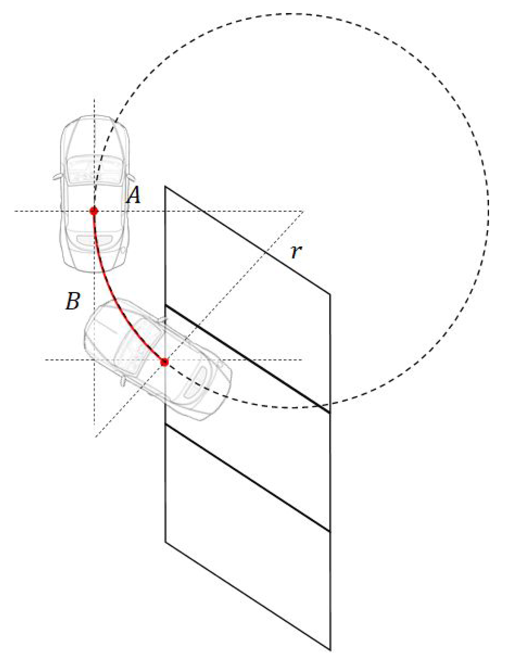
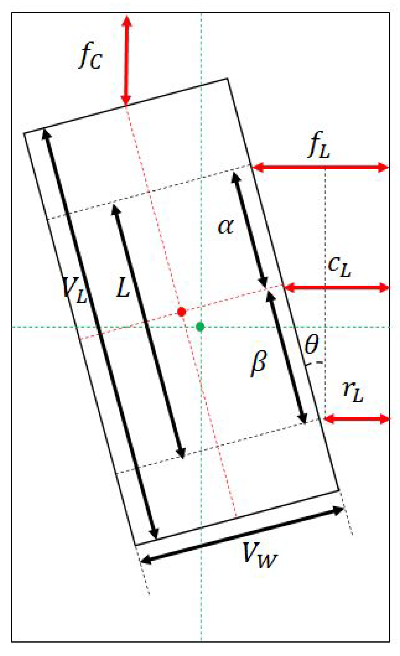
3.2.1. Motion Planning

Parking motion is divided according to the parking control method, regardless of the type of parking line [21,23].
In this study, the vehicle motion for automatic parking is divided into curved motions and straight motions [10]. Therefore, in the method proposed in this paper, when a parking path is generated, it is divided into curved sections and straight sections. If the path of the car is divided into straight sections and curved sections, the steering angle needs to be maintained at 0 in the straight section and a specific angle is adopted in the curved section to easily control the car. To find the steering angle on a curved path, δ f is calculated, as shown in Figure 9; here, δ f is the steering value and L is the wheelbase of the vehicle.
The steering control value δ f can be obtained from
δ f = tan 1 L r ,
where r is the radius of the circle drawn by the curved path and can be obtained using
r = A 2 + B 2 2 A .
In the proposed method, the paths for perpendicular, angle, and parallel parking are created by separating them into straight and curved sections in different ways [10,21].
First, for perpendicular parking, a parking path is created as shown in Figure 10. The vehicle follows a straight path and then arrives at the target point using a curved path. Then, after changing into reverse, the reverse curve is driven, and finally the parking finishes with reverse straight driving.
The curved sections for this path appear twice. The calculation of the radius r of the two paths is shown in Figure 11 where A, B are used and the steering control value is calculated from r.
Parallel parking uses the path shown in Figure 12, where, after going in a straight line and driving backwards in a curve, the vehicle curves in the opposite direction and then drives straight forward to complete the parking.
As with perpendicular parking, there are two curved sections, and the radius r for the two paths is calculated as shown in Figure 13. If A and B are defined, the steering control value can be calculated from r.
Angle parking uses the path shown in Figure 14, where the driver first drives forward in a straight line and then backward in a curve. Finally, the vehicle drives backwards in a straight line.
In angle parking, one curved section appears, and the corresponding radius r can be obtained using A and B, as shown in Figure 15.

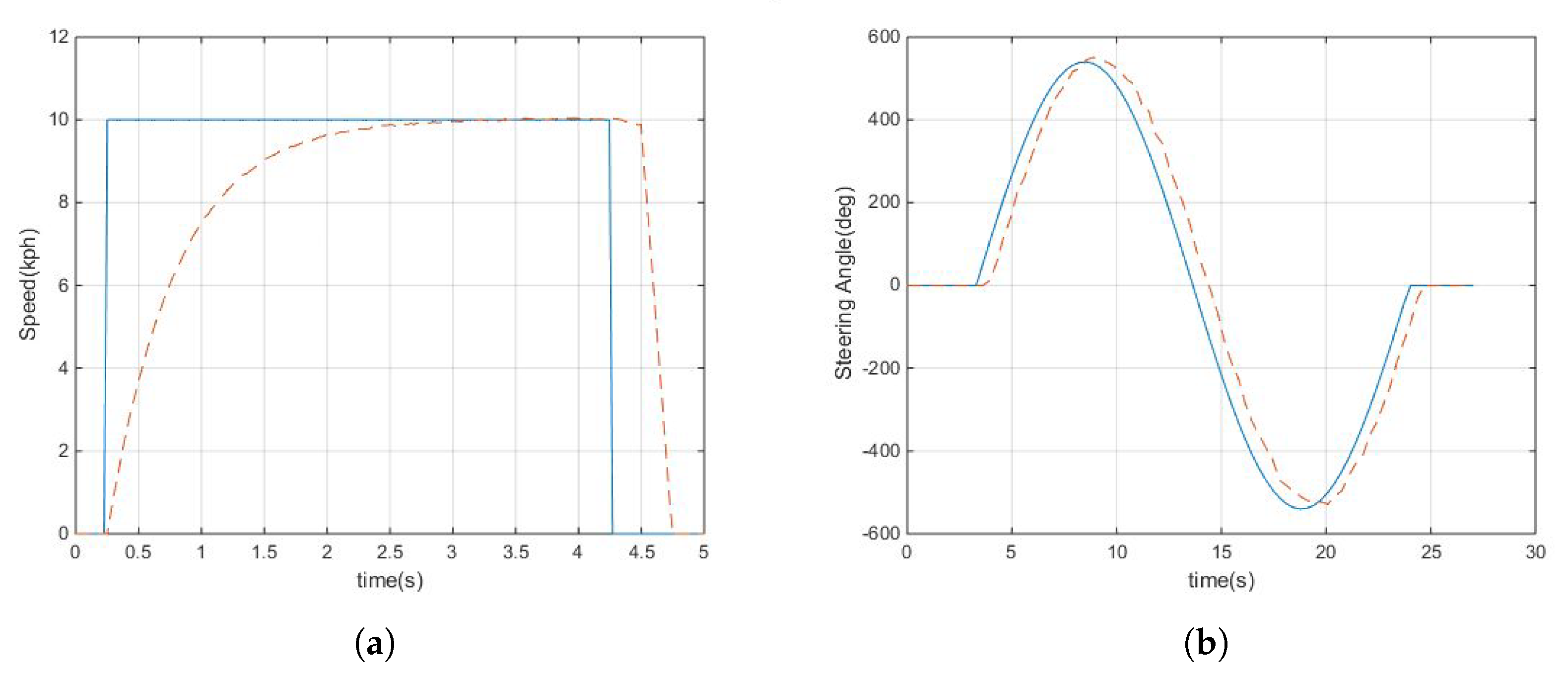
3.2.2. Motion Tracking

Motion tracking tracks the car along the generated path. During motion tracking, acceleration, braking, steering, and gear control are required to move the vehicle [36].
Automatic parking is performed at low speeds. Therefore, the target value of drive control was set to 10 kph. Based on this value, the drive control was performed using PI control, which is expressed as follows:
M V ( t ) = K p e ( t ) + K i 0 t e ( t ) d t .
As shown in Equation (5), u ( t ) is the amount of control, e ( t ) is the difference in the target speed, and K p and K i represent the gain.
In this study, electronic stability control (ESC) was used for braking. When the target point is reached using ESC, the vehicle is stopped by braking. In an automatic parking situation, because the vehicle moves at a low speed, it is possible to stop at the target point with a certain amount of braking. Therefore, when the target point is reached, this method is employed.
Gear control uses an electronic gearbox. The gear control is configured with forward, reverse, and parking gears.
The steering control is configured to follow the generated path, and for automatic parking, this is obtained as follows [10]:
ϕ ( t ) = ϕ ( t 1 ) + K p e 1 ( t ) + K d ( e 1 ( t ) 2 e 1 ( t 1 ) + e 2 ( t ) ) .
Here, ϕ is the steering angle, K p and K d represent the gain, e 1 represents the closest difference between the curve at the target point and the straight line connecting the center point of the vehicle, and e 2 represents the closest difference between the curve at the target point and the curve of the vehicle.
Figure 16 shows the results of vehicle speed control and steering control. Figure 16a shows the speed control result, and Figure 16b shows the steering control result. As shown in Figure 16, the velocity and steering angle are tracked to the target.

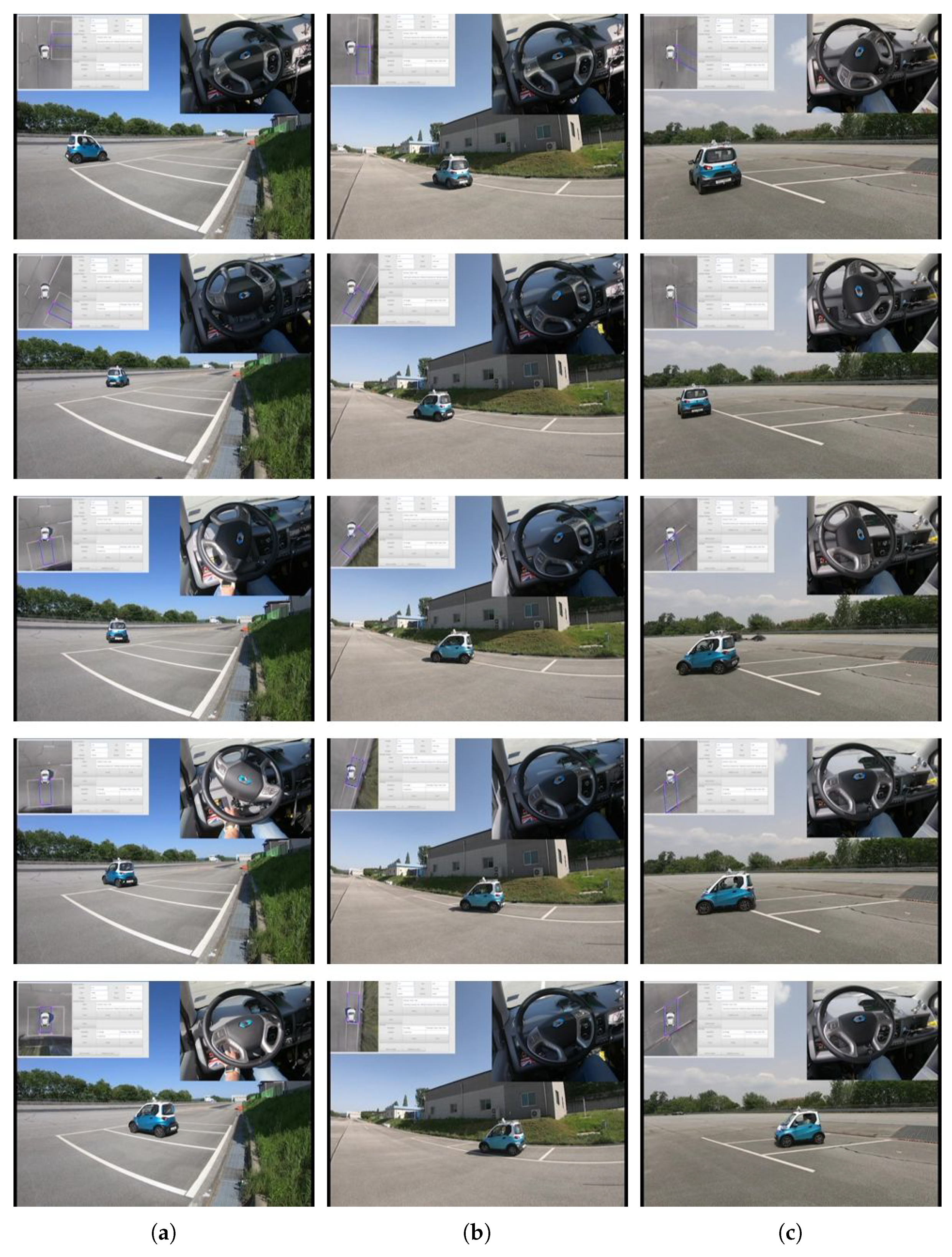
4. Experimental Results

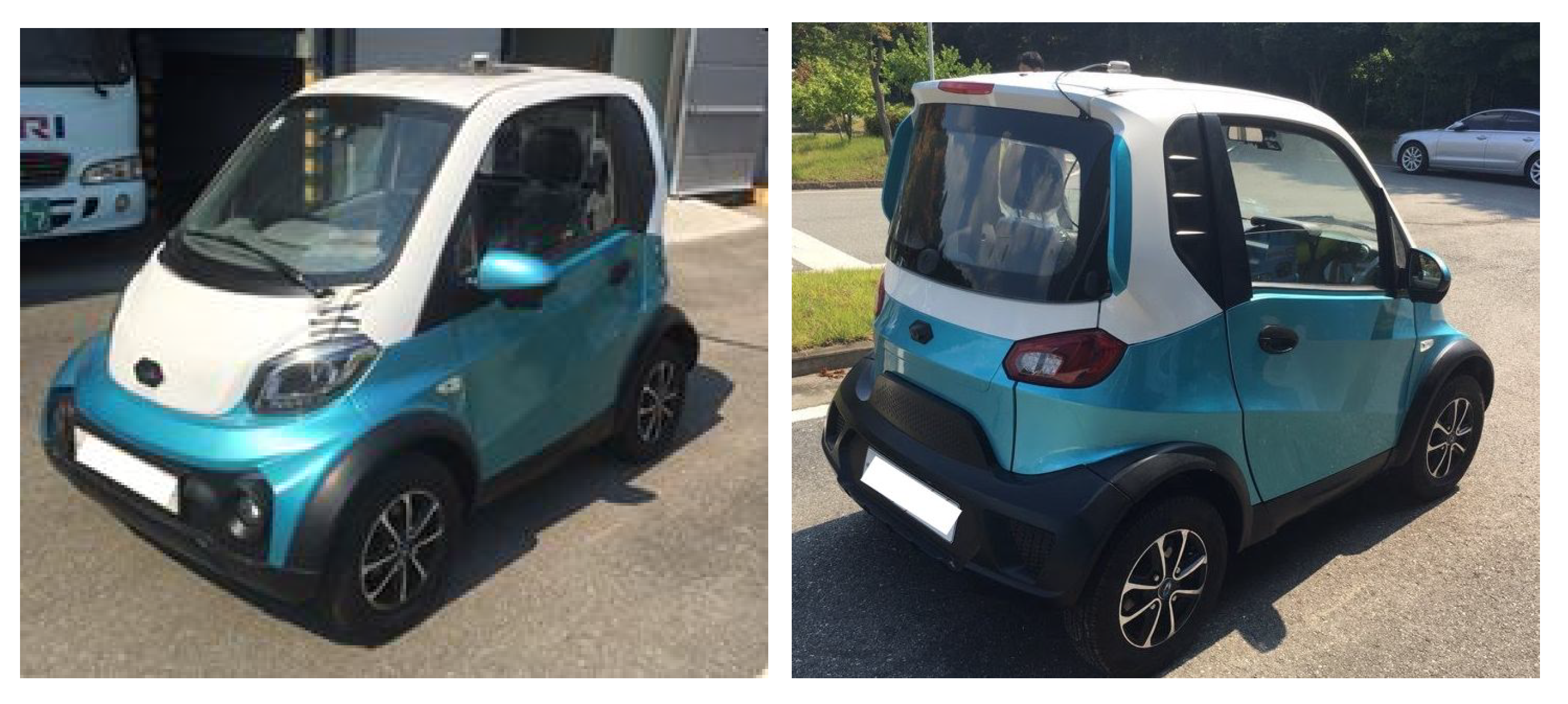
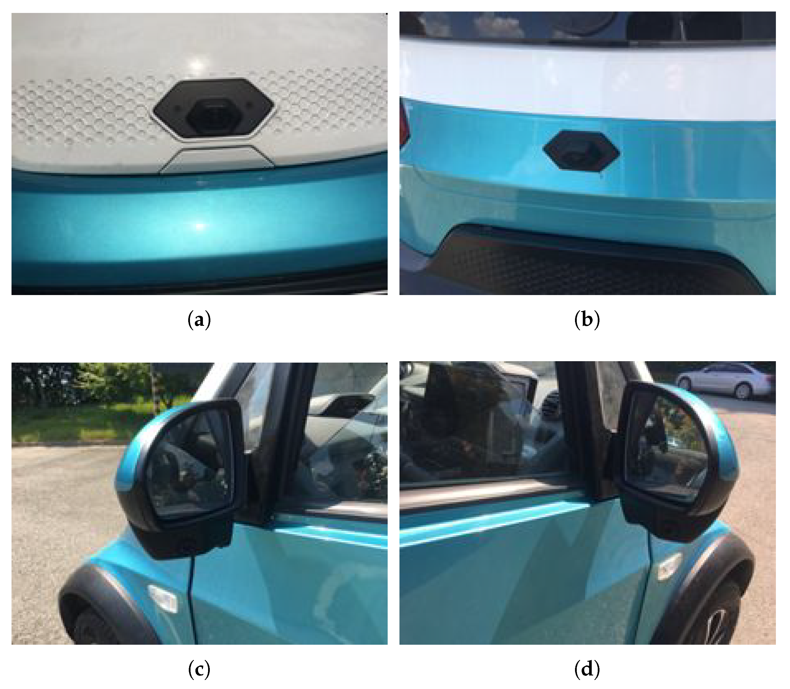
4.1. Experimental Environment

For the test, the experiment environment was first configured. High-definition cameras (1280 × 720) were installed on the test vehicle, which was a Cammsys CEVO-C small electric vehicle [37] that was modified for automatic parking. Electronic power steering was installed in the test vehicle for steering control, and ESC was installed in the test vehicle for braking control. In addition, the drive control used the electric vehicle’s motor, and the gear was configured so that it could be changed using electronic control. Figure 17 shows the test vehicle.
Figure 18 shows the cameras mounted on the front, rear, left and right sides of the test vehicle.
Test images were acquired in various situations using the cameras mounted on the test vehicle. Figure 19 shows examples of images acquired at each parking slot. As shown, images were obtained in various situations, especially where it was difficult to detect parking lines.
The automatic parking experiment was conducted on three types of parking slots: perpendicular, parallel, and angle parking slots (Figure 20a–c, respectively).

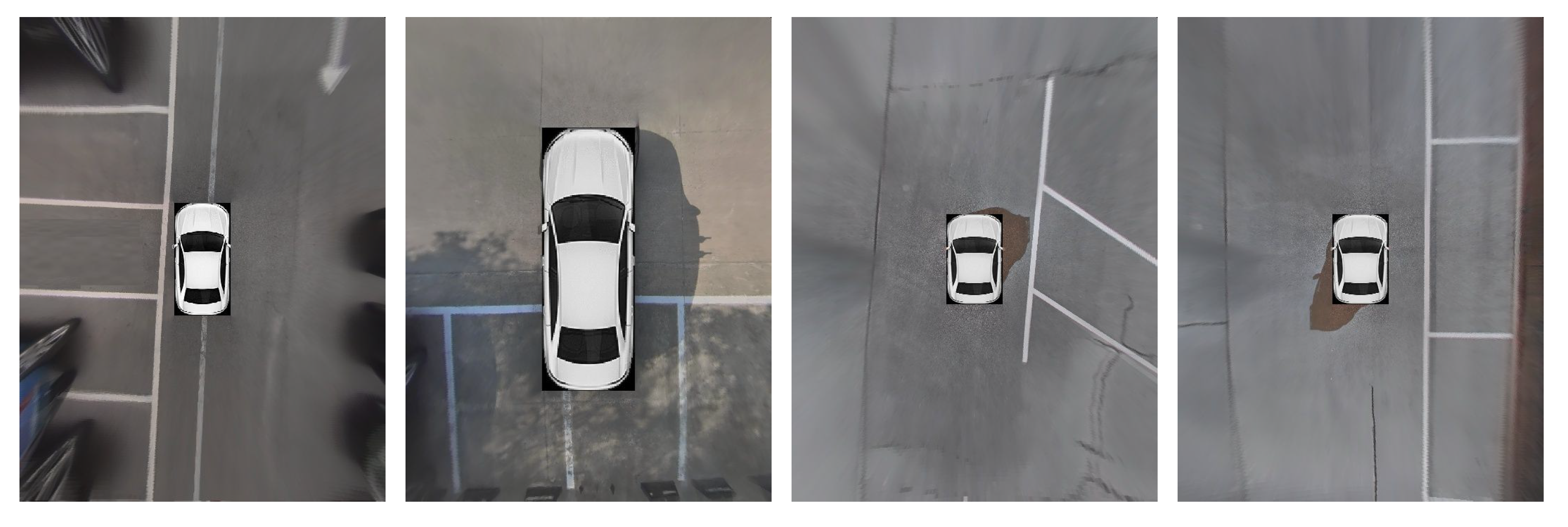
4.2. Experimental Results

Experiments were conducted to evaluate the recognition of parking lines and automatic parking performance of the proposed method.
A dataset was used to evaluate the detection rate of the parking line detection method. The dataset consisted of images of square, angle, open, diamond, and parallel parking slots.
In addition, the detection rate was evaluated using precision and recall, which were calculated as follows [16]:
p r e c i s i o n = N o . o f c o r r e c t l y d e t e c t e d p a r k i n g s l o t s N o . o f d e t e c t e d p a r k i n g s l o t s .
r e c a l l = N o . o f c o r r e c t l y d e t e c t e d p a r k i n g s l o t s N o . o f p a r k i n g s l o t s .
Table 1 and Table 2 compare the results obtained without and with the CNN, respectively. When the CNN was used, the average precision was 96 % and the recall was 94 % , which are better results than those obtained when the CNN was not used.
Figure 21 shows the detected parking slotd. The results confirm that various parking line types could be recognized in different environments.
In the automatic parking experiment, we evaluated the final position after parking. We employed a method to compare the final position and target position after the direct measurement of several points, as illustrated in Figure 22.
As shown in Figure 22, the distance between each wheel and the parking line as well as the distance between the center of the front of the vehicle and the parking slot were measured. From the positions of these three points, the amount of offset from the center and the heading angle can be obtained. Using the configuration shown in Figure 22, the angle of the vehicle can be obtained as follows:
θ = sin 1 f L r L L .
Using angle θ , the difference in the y-axis direction away from the center can be expressed as
D y = P y 2 V L 2 cos θ + f c .
In addition, the x-axis offset can be obtained from
D x = P x 2 V W 2 cos θ + c L .
The experiment was conducted considering the shape of each parking slot. There were three types of parking division lines in the experiment: perpendicular, parallel, and angle parking lines. The results were obtained by detecting the parking slot according to its type and performing automatic parking. Table 3 presents the experimental results (the lateral error, longitudinal error, and heading angle) for each parking slot type.
Figure 23 shows the automatic parking results; the upper-left inset image shows the parking slot detection and the upper-right inset image shows the inside of the car. These results confirm that automatic parking using the proposed method was successful.

5. Conclusions and Future Works

5.1. Conclusions

In this paper, we proposed a method for detecting parking slots using an AVM system and using it to perform automatic parking. In the method proposed in this study, feature maps were extracted using a line filter and parking lines were extracted via the Hough transform. In addition, the corners were detected by extracting the parking lines, and the parking slot corner were identified using a deep-learning method (a CNN) that was trained on a database of various environments for more reliable results. In addition, to handle the situation where the parking line is occluded by the movement of the vehicle during automatic parking, the accuracy was improved by tracking the parking line using a Kalman filter from the start of the parking until its completion. This maintained the information on the position of the parking line until the end of the actual automatic parking.
Using the detected parking lines, a parking path was created using circles and lines. Parking was performed along the created parking path. It was evaluated using an actual test vehicle, and it was confirmed that automatic parking could be completed within a heading angle error of 2 . 5 , an x-axis offset of 26 cm, and a y-axis offset of 27 cm.

5.2. Future Works

In parking slot detection, because there are various types of corner points, it takes a lot of time to collect the data and train the model. We plan to improve detection performance by collecting data to train the model to detect various types of corner points. In addition, when tracking the parking slot, a Kalman filter was used, but the vehicle motion information was not used. The accuracy of the Kalman filter tracking would be improved by also using the vehicle’s motion information.
The proposed automatic parking control method used circular and linear motions. It currently does not consider the case where the opposite side is blocked. Therefore, we plan to create a parking trajectory considering the case in which an obstacle such as a wall or vehicle blocks the way on the opposite side. Parking in a narrow space is possible by increasing the number of forward and backward motions. Such changes to the method of creating the parking trajectory will enable automatic parking even in tight spaces.
In addition, obstacle detection will be added to detect parking slots with obstacles. Deep learning can be used for obstacle detection. This will be implemented so that a vehicle can be automatically parked in an empty parking lot using the obstacle information and parking corner points.

Author Contributions

Y.L. developed the algorithm and performed the experiments. M.P. contributed to the development of the algorithm, validation of the experiments, and research supervision. Y.L. contributed to the writing of the manuscript. M.P. contributed to the review and editing of the manuscript. All authors have read and agreed to the published version of the manuscript.

Funding

This work was supported by the Technology Innovation Program (or Industrial Strategic Technology Development Program—Automobile Industrial Core Technology Development Project) (grant no. K_G012000307004, Development of rear automatic braking system for NCAP) funded by the Ministry of Trade, Industry and Energy (MOTIE, Korea). This work was further supported by the System Industrial Strategic Technology Development Program (grant no. 10079961, Development of a deterministic DCU platform with less than 1 us synchronization for autonomous driving system control) funded by the Ministry of Trade, Industry, and Energy (MOTIE, Korea). Support was also provided by the Basic Science Research Program of the National Research Foundation of Korea (NRF) funded by the Ministry of Education under grant no. 2018R1D1A1B0704814314.

Conflicts of Interest

The authors declare no conflict of interest.

References

  1. Trivedi, M.M.; Gandhi, T.; McCall, J. Looking-in and looking-out of a vehicle: Computer-vision-based enhanced vehicle safety. IEEE Trans. Intell. Transp. Syst. 2007, 8, 108–120. [Google Scholar] [CrossRef] [Green Version]
  2. Jung, H.G.; Kim, D.S.; Yoon, P.J.; Kim, J. Parking slot markings recognition for automatic parking assist system. In Proceedings of the 2006 IEEE Intelligent Vehicles Symposium, Tokyo, Japan, 13–15 June 2006; pp. 106–113. [Google Scholar]
  3. Satonaka, H.; Okuda, M.; Hayasaka, S.; Endo, T.; Tanaka, Y.; Yoshida, T. Development of parking space detection using an ultrasonic sensor. In Proceedings of the 13th ITS World Congress, London, UK, 8–12 October 2006. [Google Scholar]
  4. Lee, Y.; Chang, S. Development of a verification method on ultrasonic-based perpendicular parking assist system. In Proceedings of the 18th IEEE International Symposium on Consumer Electronics (ISCE 2014), Jeju, Korea, 22–25 June 2014; pp. 1–3. [Google Scholar]
  5. Liu, Y.C.; Lin, K.Y.; Chen, Y.S. Bird’s-eye view vision system for vehicle surrounding monitoring. In International Workshop on Robot Vision; Springer: Auckland, New Zealand, 18–20 February 2008; pp. 207–218. [Google Scholar]
  6. Kum, C.H.; Cho, D.C.; Ra, M.S.; Kim, W.Y. Lane detection system with around view monitoring for intelligent vehicle. In Proceedings of the 2013 International SoC Design Conference (ISOCC), IEEE, Busan, Korea, 17–19 November 2013; pp. 215–218. [Google Scholar]
  7. Lee, Y.H.; Kim, W.Y. An automatic calibration method for AVM cameras. IEEE Access 2020, 8, 192073–192086. [Google Scholar] [CrossRef]
  8. Hamada, K.; Hu, Z.; Fan, M.; Chen, H. Surround view based parking lot detection and tracking. In Proceedings of the 2015 IEEE Intelligent Vehicles Symposium (IV), Seoul, Korea, 28 June–1 July 2015; pp. 1106–1111. [Google Scholar]
  9. Lee, S.; Hyeon, D.; Park, G.; Baek, I.J.; Kim, S.W.; Seo, S.W. Directional-DBSCAN: Parking-slot detection using a clustering method in around-view monitoring system. In Proceedings of the 2016 IEEE Intelligent Vehicles Symposium (IV), Gothenburg, Sweden, 19–22 June 2016; pp. 349–354. [Google Scholar]
  10. Wang, C.; Zhang, H.; Yang, M.; Wang, X.; Ye, L.; Guo, C. Automatic parking based on a bird’s eye view vision system. Adv. Mech. Eng. 2014, 6, 1–10. [Google Scholar] [CrossRef]
  11. Houben, S.; Komar, M.; Hohm, A.; Lüke, S.; Neuhausen, M.; Schlipsing, M. On-vehicle video-based parking lot recognition with fisheye optics. In Proceedings of the 16th International IEEE Conference on Intelligent Transportation Systems (ITSC 2013), Hague, The Netherlands, 6–9 October 2013; pp. 7–12. [Google Scholar]
  12. Suhr, J.K.; Jung, H.G. A universal vacant parking slot recognition system using sensors mounted on off-the-shelf vehicles. Sensors 2018, 18, 1213. [Google Scholar] [CrossRef] [PubMed] [Green Version]
  13. Chen, J.Y.; Hsu, C.M. A visual method tor the detection of available parking slots. In Proceedings of the 2017 IEEE International Conference on Systems, Man, and Cybernetics (SMC), Banff, AB, Canada, 5–8 October 2017; pp. 2980–2985. [Google Scholar]
  14. Lee, M.; Kim, S.; Lim, W.; Sunwoo, M. Probabilistic occupancy filter for parking slot marker detection in an autonomous parking system using avm. IEEE Trans. Intell. Transp. Syst. 2018, 20, 2389–2394. [Google Scholar] [CrossRef]
  15. Zhang, L.; Li, X.; Huang, J.; Shen, Y.; Wang, D. Vision-based parking-slot detection: A benchmark and a learning-based approach. Symmetry 2018, 10, 64. [Google Scholar] [CrossRef] [Green Version]
  16. Kim, S.; Kim, J.; Ra, M.; Kim, W.Y. Vacant parking slot recognition method for practical autonomous valet parking system using around view image. Symmetry 2020, 12, 1725. [Google Scholar] [CrossRef]
  17. Kim, C.; Cho, S.; Jang, C.; Sunwoo, M.; Jo, K. Evidence filter of semantic segmented image from around view monitor in automated parking system. IEEE Access 2019, 7, 92791–92804. [Google Scholar] [CrossRef]
  18. Zhang, L.; Huang, J.; Li, X.; Xiong, L. Vision-based parking-slot detection: A DCNN-based approach and a large-scale benchmark dataset. IEEE Trans. Image Process. 2018, 27, 5350–5364. [Google Scholar] [CrossRef] [PubMed]
  19. Allodi, M.; Castangia, L.; Cionini, A.; Valenti, F. Monocular parking slots and obstacles detection and tracking. In Proceedings of the 2016 IEEE Intelligent Vehicles Symposium (IV), Gothenburg, Sweden, 19–22 June 2016; pp. 179–185. [Google Scholar]
  20. Lee, S.; Seo, S.W. Available parking slot recognition based on slot context analysis. IET Intell. Transp. Syst. 2016, 10, 594–604. [Google Scholar] [CrossRef]
  21. Zips, P.; Böck, M.; Kugi, A. A fast motion planning algorithm for car parking based on static optimization. In Proceedings of the 2013 IEEE/RSJ International Conference on Intelligent Robots and Systems, Tokyo, Japan, 3–7 November 2013; pp. 2392–2397. [Google Scholar]
  22. Zips, P.; Böck, M.; Kugi, A. Optimisation based path planning for car parking in narrow environments. Robot. Auton. Syst. 2016, 79, 1–11. [Google Scholar] [CrossRef]
  23. Lin, L.; Zhu, J.J. Path planning for autonomous car parking. In Proceedings of the Dynamic Systems and Control Conference, American Society of Mechanical Engineers, Atlanta, GA, USA, 30 September–3 October 2018; pp. 1–10. [Google Scholar]
  24. Sedighi, S.; Nguyen, D.V.; Kuhnert, K.D. A new method of clothoid-based path planning algorithm for narrow perpendicular parking spaces. In Proceedings of the 5th International Conference on Mechatronics and Robotics Engineering, Rome, Italy, 16–18 February 2019; pp. 50–55. [Google Scholar]
  25. Kim, D.J.; Chung, C.C. Automated Perpendicular Parking System with Approximated Clothoid-Based Local Path Planning. IEEE Control. Syst. Lett. 2020, 5, 1940–1945. [Google Scholar] [CrossRef]
  26. Vorobieva, H.; Glaser, S.; Minoiu-Enache, N.; Mammar, S. Automatic parallel parking in tiny spots: Path planning and control. IEEE Trans. Intell. Transp. Syst. 2015, 16, 396–410. [Google Scholar] [CrossRef] [Green Version]
  27. Li, T.-H.; Chang, S.-J. Autonomous fuzzy parking control of a car-like mobile robot. IEEE Trans. Syst. Man Cybern.-Part A Syst. Hum. 2003, 33, 451–465. [Google Scholar] [CrossRef]
  28. Kim, D.; Chung, W. Motion planning for car-parking using the slice projection technique. In Proceedings of the 2008 IEEE/RSJ International Conference on Intelligent Robots and Systems, Nice, France, 22–26 September 2008; pp. 1050–1055. [Google Scholar]
  29. Kwon, H.; Chung, W. Performance analysis of path planners for car-like vehicles toward automatic parking control. Intell. Serv. Robot. 2014, 7, 15–23. [Google Scholar] [CrossRef]
  30. Krizhevsky, A.; Sutskever, I.; Hinton, G.E. Imagenet classification with deep convolutional neural networks. Adv. Neural Inf. Process. Syst. 2012, 25, 1097–1105. [Google Scholar] [CrossRef]
  31. Zeiler, M.D.; Fergus, R. Visualizing and understanding convolutional networks. In European Conference on Computer Vision; Springer: Zurich, Switzerland, 6–12 September 2014; pp. 818–833. [Google Scholar]
  32. Simonyan, K.; Zisserman, A. Very deep convolutional networks for large-scale image recognition. arXiv 2014, arXiv:1409.1556. [Google Scholar]
  33. Szegedy, C.; Liu, W.; Jia, Y.; Sermanet, P.; Reed, S.; Anguelov, D.; Erhan, D.; Vanhoucke, V.; Rabinovich, A. Going deeper with convolutions. In Proceedings of the IEEE Conference on Computer Vision and Pattern Recognition(CVPR), Boston, MA, USA, 7–12 June 2015; pp. 1–9. [Google Scholar]
  34. LeCun, Y.; Bottou, L.; Bengio, Y.; Haffner, P. Gradient-based learning applied to document recognition. Proc. IEEE 1998, 86, 2278–2324. [Google Scholar] [CrossRef] [Green Version]
  35. Peizhi, Z.; Zhuoping, Y.; Lu, X.; Dequan, Z. Research on Parking Slot Tracking Algorithm Based on Fusion of Vision and Vehicle Chassis Information. Int. J. Automot. Technol. 2020, 21, 603–614. [Google Scholar]
  36. Park, M.; Lee, S.; Kim, M.; Lee, J.; Yi, K. Integrated differential braking and electric power steering control for advanced lane-change assist systems. Proc. Inst. Mech. Eng. Part D J. Automob. Eng. 2015, 229, 924–943. [Google Scholar] [CrossRef]
  37. Cammsys Corp. CEVO-C. Available online: https://www.cevo.co.kr/ (accessed on 25 October 2021).
Figure 1. Proposed automatic parking system using AVM images.
Applsci 11 11905 g001
Figure 2. Line filter.
Applsci 11 11905 g002
Figure 3. Line filter results: (a) AVM image, (b) vertical line filter results, (c) horizontal line filter results, and (d) combined results of (b,c).
Applsci 11 11905 g003
Figure 4. Corner detection example: (a) Hough transform result and (b) corner detection result.
Applsci 11 11905 g004
Figure 5. Layers of the CNN.
Applsci 11 11905 g005
Figure 6. Parking slot corner true and false data examples: (a) extraction of corner point candidates, and (b) true and false corner point examples.
Applsci 11 11905 g006
Figure 7. Examples of parking lines occluded by the vehicle.
Applsci 11 11905 g007
Figure 8. Parking slot tracking example.
Applsci 11 11905 g008
Figure 9. Vehicle parameters for calculating the angle in curved motion.
Applsci 11 11905 g009
Figure 10. Perpendicular parking trajectory.
Applsci 11 11905 g010
Figure 11. Calculation of r in the perpendicular parking trajectory: (a) calculation of the first circular trajectory and (b) calculation of the second circular trajectory.
Applsci 11 11905 g011
Figure 12. Parallel parking trajectory.
Applsci 11 11905 g012
Figure 13. Calculation of r in the parallel parking trajectory: (a) calculation of the first circular trajectory and (b) calculation of the second circular trajectory.
Applsci 11 11905 g013
Figure 14. Angle parking trajectory.
Applsci 11 11905 g014
Figure 15. Calcuation of r in the angle parking trajectory.
Applsci 11 11905 g015
Figure 16. Results of speed and steering control: (a) result of speed control and (b) result of steering control.
Applsci 11 11905 g016
Figure 17. Test vehicle.
Applsci 11 11905 g017
Figure 18. AVM camera installation: (a) front camera, (b) rear camera, (c) left camera, and (d) right camera.
Applsci 11 11905 g018
Figure 19. Examples of parking line images.
Applsci 11 11905 g019
Figure 20. Parking slots for the automatic parking test: (a) perpendicular, (b) angle, and (c) parallel parking slots.
Applsci 11 11905 g020
Figure 21. Parking slot detection results.
Applsci 11 11905 g021
Figure 22. Measurement points for automatic parking result evaluation.
Applsci 11 11905 g022
Figure 23. Automatic parking results: (a) perpendicular parking result, (b) parallel parking result, and (c) angle parking result.
Applsci 11 11905 g023
Table 1. Parking slot detection results obtained without the CNN.
Parking Slot
Type
No. of
Parking Slots
No. of
Detected Slots
No. of
Miss Detections
No. of
Wrong Detections
PrecisionRecall
Perpendicular468440471995.6889.96
Angle259243271195.4789.57
Parallel938812792.0487.10
Sum820771863495.289.51
Table 2. Parking slot detection results using the CNN.
Parking Slot
Type
No. of
Parking Slots
No. of
Detected Slots
No. of
Miss Detections
No. of
Wrong Detections
PrecisionRecall
Perpendicular468458231397.1695.08
Angle25925314896.8494.59
Parallel93907495.5692.47
Sum820801442596.8894.63
Table 3. Results of automatic parking using the AVM-based system.
Parking TypeNo.X OffsetY OffsetHeading Angle
10.0530.2040.1
20.270.2110.5
30.0750.1970.4
40.110.0230.2
Perpendicular50.1040.0240.2
parking60.0640.010.2
70.0280.1730.4
80.0720.1620.3
90.0830.0740.2
100.0530.2040.1
10.0690.0832.4
20.1430.0041.7
30.20.0161.1
40.1780.0531.4
Angle50.1120.0021.3
parking60.1910.0672.1
70.1360.0482.2
80.1050.0091.2
90.2540.0071.0
100.1540.0231.6
10.0730.1080.8
20.0960.1141.2
30.0580.0990.7
40.0410.1040.6
Parallel50.1090.0891.1
parking60.1720.1040.7
70.1380.0981.2
80.0770.0871.4
90.0480.1121.0
100.040.0970.9
Average 0.10270.08890.94
Publisher’s Note: MDPI stays neutral with regard to jurisdictional claims in published maps and institutional affiliations.

