
Tissue Engineering 3D Porous Scaffolds Prepared from Electrospun Recombinant Human Collagen (RHC) Polypeptides/Chitosan Nanofibers

1
School of Environmental and Biological Engineering, Nanjing University of Science and Technology, Nanjing 210094, China
2
Biomanufacturing Center, Department of Mechanical Engineering, Tsinghua University, Beijing 100084, China
*
Author to whom correspondence should be addressed.
†
Contributed equally to this work as co-first authors.
Appl. Sci. 2021, 11(11), 5096; https://doi.org/10.3390/app11115096
Submission received: 4 May 2021
/
Revised: 27 May 2021
/
Accepted: 28 May 2021
/
Published: 31 May 2021
Abstract
:Electrospinning, the only method that can continuously produce nanofibers, has been widely used to prepare nanofibers for tissue engineering applications. However, electrospinning is not suitable for preparing clinically relevant three-dimensional (3D) nanofibrous scaffolds with hierarchical pore structures. In this study, recombinant human collagen (RHC)/chitosan nanofibers prepared by electrospinning were combined with porous scaffolds produced by freeze drying to fabricate 3D nanofibrous scaffolds. These scaffolds exhibited high porosity (over 80%) and an interconnected porous structure (ranging from sub-micrometers to 200 μm) covered with nanofibers. As confirmed by the characterization results, these scaffolds showed good swelling ability, stability, and adequate mechanical strength, making it possible to use the 3D nanofibrous scaffolds in various tissue engineering applications. In addition, after seven days of cell culturing, NIH 3T3 was infiltrated into the scaffolds while maintaining its morphology and with superior proliferation and viability. These results indicated that the 3D nanofibrous scaffolds hold great promise for tissue engineering applications.
1. Introduction
Tissue engineering scaffolds should provide adequate three-dimensional (3D) microenvironments for cell adhesion, proliferation, differentiation, and natural extracellular matrix (ECM) deposition [1]. The physical and chemical properties of these scaffolds are key factors in tissue regeneration [2,3]. With the increasing understanding of the intrinsic interactions between cells and their microenvironment, the preparation of scaffolds mimicking the compositional and structural aspects of ECMs has received growing attention [4,5]. Since naturally occurring ECMs are mainly composed of nano-scale collagen fibers, to date, several fabricating methods (e.g., phase separation, self-assembly, and electrospinning) have been applied to prepare biomimetic scaffolds with nanofibrous structures [6,7,8]. Of these methods, electrospinning is the only technique that allows the continuous production of fibers at micro or nanoscales [9]. Electrospinning has attracted great attention because of its material versatility, straightforward nature, and cost-effectiveness [10,11]. Although electrospinning-manufactured nanofibers possess a large specific surface area, high porosity, and spatial interconnectivity, electrospun nanofibrous mats still lack macroporous structures [12]. As a result, the intrinsically small interfiber pore size of these materials hinders cell penetration across the layers, which is necessary in forming integrated tissues. In addition, the small interfiber pore size of electrospun nanofibrous mats constrains infiltration into the cell itself, hindering its integration with the host tissue upon in vivo implantation [13]. Sacrificial microbeads, particulate leaching, freeze drying, and cryogenic electrospinning have been used in an attempt to increase the pore size of these products [14]. However, nanofibrous mats with large pore sizes (ca. 100–200 μm) and highly interconnected pore structures for the transport of cells and metabolites have not been well achieved yet [15,16].
Three-dimensional (3D) porous scaffolds play an important role in tissue engineering, as they can provide vital frameworks for cell proliferation, migration, and differentiation into specific tissues while secreting ECM components [17]. Scaffolds with complex, and often anisotropic, porous microstructures have been prepared via freeze-drying cycles by controlling the freezing temperature and rate [18]. These porous microstructures provide nutrients, transfer oxygen, and remove waste. In addition, pores of varying sizes are critical for tissue repair, since neovascularization, fibroblast ingrowth, skin regeneration, and bone regeneration require different pore sizes [19]. However, the inherent lack of mechanical strength associated with porosity is a common problem with these porous scaffolds and limits further applications of these materials.
Synthetic polymers such as polycaprolactone, polylactic acid, and poly(lactic-co-glycolic acid) are frequently used to fabricate fibers or porous scaffolds in tissue engineering, and previous studies already showed their compatibility to the cells. By in vivo studies, these biomaterials showed too slow degradation rates [20], which are not suitable for some of the applications, such as soft tissue and skin regeneration. Both chitosan and collagen are natural derived materials that have been widely used in tissue engineering because of their excellent biocompatibility, biodegradability, biological activity, and low immunogenicity [21,22]. Chitosan, obtained by the deacetylation of chitin, is one of the most abundant polysaccharides, while collagen is a significant component of ECMs. In addition, chitosan and collagen are usually combined to mimic the composition of natural ECMs and improve their physical properties [23,24]. Collagen used in tissue engineering is mainly obtained from animal tissues and considered protein of xenogeneic origin, and its purity and quality are not always consistent [25]. Recombinant human collagen (RHC), known as non-animal sourced material, can be applied as novel biomaterial to eliminate potential disease transmissions and allergic reactions [26].
Although solution electrospinning had been developed to produce porous fibrous scaffolds that facilitate cellular penetration in previous studies [12], to date, only a few studies were conducted by using recombinant human collagen as a biomaterial to produce tissue engineering porous scaffolds with the presenting of electrospun nanofibers [27]. In this study, we report a method that combines electrospinning and freeze drying to create 3D porous scaffolds formed by nanofibers. First, the chitosan/RHC nanofibrous prepared by electrospinning was converted into short individual nanofibers and tiny nanofibrous pieces, which were subsequently combined with freeze drying to prepare 3D porous scaffolds. The resulting 3D nanofibrous scaffolds showed porosity higher than 80% and a complex, anisotropic porous microstructure with pore sizes ranging from 20 to 300 μm. Moreover, nanofibers were found to cover the surface of the scaffolds, presenting a nanoscale morphology. Subsequently, mechanical tests revealed that the incorporation of nanofibers significantly improved the stiffness of the scaffolds. In vitro studies also showed that the scaffolds were biocompatible, allowing cells to infiltrate the inner part of the scaffolds. Therefore, the resulting scaffolds could be used as an ECM template holding great promise for tissue engineering applications.
2. Materials and Methods
2.1. Materials
RHC (Mw.112 kD) was purified and collected from the fermentation supernatant of Pichia pastoris which contained type III recombinant human collagen expression vectors [28]. Chitosan (Mw. 100–200 kD, 90% deacetylated, viscosity <100 cps) was purchased from Lanji Co. Ltd. (Shanghai, China). From Yuanye (Shanghai, China), we obtained 1-ethyl-3-(3-dimethylaminopropyl) carbodiimide hydrochloride (EDC). Dulbecco’s modified eagle medium (DMEM), fetal bovine serum (FBS), and trypsin were bought from Hyclone. The rest of the chemicals were of analytical quality and obtained from Sinopharm Chemical Reagent (Shanghai, China).
2.2. Fabrication of the Chitosan/RHC Nanofibers
The chitosan/RHC nanofibers crosslinked in situ were prepared by electrospinning as previously reported [27]. Briefly, chitosan powder was dissolved in 0.2 M acetic acid to prepare a 6% (w/v) chitosan solution. RHC and polyethylene oxide (PEO) were dissolved in a mixture solvent containing 3% acetic acid/ethanol (with a volume ratio of 10/1). After 20 mM EDC were added to the RHC solution and reacted for 10 min, chitosan, RHC, and PEO were blended at a volume ratio of 4:4:1. Then, the electrospinning solution was transferred to a 10 mL syringe with a 22-gauge 90° blunt end stainless-steel needle with a feed rate of 0.5 mL/h. A high voltage of 16 kV was applied to the needle, and the resulting nanofibers were collected on a roller covered with a gauze placed at a distance of 16 cm. Finally, the formed electrospun nanofibrous membranes were carefully peeled off by tweezers.
2.3. Fabrication of the 3D Nanofibrous Scaffolds
Chitosan was dissolved in a 0.2 M acetic acid solution, dialyzed, and lyophilized. In a subsequent step, RHC and chitosan were mixed and dissolved in deionized water. One gram of nanofibrous membranes was first cut into small pieces and suspended in 100 mL of a 90% ethanol solution. Then, short nanofibers and tiny nanofibrous pieces were produced by homogenizing the mixture for 15 min at 12,000 rpm using an IKA T18 homogenizing device (IKA, Staufen, Germany). Subsequently, 0, 0.5, and 1 mL of the mixture were centrifuged to collect the short individual nanofibers and the tiny nanofibrous pieces. To fabricate the 3D nanofibrous scaffolds, the collected fibers were re-suspended in 1% or 2% chitosan/RHC aqueous solutions, then frozen at −20 °C for 24 h, and lyophilized for additional 24 h. Finally, the freeze-dried scaffolds were crosslinked in 20 mM EDC dissolved in 90% ethanol for 4 h, washed, and lyophilized. Four types of scaffolds (1%-0 mL, 1%-0.5 mL, 1%-1 mL, and 2%-1 mL) were respectively fabricated by re-suspending 0, 0.5, 1, and 2 mL of nanofibers in 1% or 2% chitosan/RHC aqueous solutions.
2.4. Characterization
2.4.1. Morphology Analysis of the Nanofibers and Scaffolds
The short nanofibers were dispersed in ethanol, diluted, and dripped on a monocrystalline silicon chip to allow air drying. All the electrospun membranes, short nanofibers, and 3D nanofibrous scaffolds were sputter-coated with gold, and their morphologies were observed by scanning electron microscopy (SEM, FEI Quant 250F, FEI Company, Hillsboro, OR, USA) at an accelerating voltage of 15 kV. Image-J (National Institutes of Health, Bethesda, MD, USA) was used to determine the diameters of the nanofibers and the pore sizes. The diameter distributions were determined by analyzing at least 100 random fibers from the SEM pictures.
2.4.2. Open Porosity
The porosity of the as-prepared 3D nanofibrous scaffolds was determined using the liquid displacement method [29]. Ethanol was chosen as a displacement liquid because it could permeate through the porous scaffolds without swelling or shrinking the material. The weight of the scaffold was measured as m1, while a bottle filled with ethanol was weighted as m2. Scaffold was immersed into the bottle, and the excess ethanol was removed; the weight of the bottle, including ethanol and scaffold, was set as m3. Lastly, the scaffold was taken out, and the weight of the bottle with the remaining ethanol was m4. The measurements were conducted at 24 °C. The porosity of the scaffold was determined as follows:
P (%) = (m3 − m4 − m1)/(m2 − m4) × 100%.
2.4.3. Swelling Ability
The swelling ability was determined using the weighing method [27]. Briefly, dry scaffolds were weighed (W0) and subsequently immersed in distilled water at 37 °C for 5 min. The soaked scaffolds were taken out and weighted after the excess water was wiped. The above procedure was repeated until the weight of the soaked scaffolds remained constant, and it was set as W1. The swelling ability was determined as follows:
S (%) = (W1 − W0)/W0 × 100%.
2.4.4. Degradation
The weight of the dry 3D nanofibrous scaffolds was measured and set as W0. The degradation rate of various scaffolds was measured in vitro by degradation in a lysozyme solution (2 mg/mL dissolved in phosphate-buffered saline (PBS)) at 37 °C for 30 days [27]. A lysozyme solution was freshly changed once a week. At the end of each time period, the scaffolds were taken out, rinsed with deionized water, and lyophilized. The weights were measured and set as Wt. The degradation rate was determined as follows:
Degradation rate (%) = (W0 − Wt)/W0 × 100%.
2.4.5. Fourier Transform Infrared Spectroscopy (FT-IR)
FT-IR spectra of the RHC and fabricated 3D nanofibrous scaffolds were obtained from a Thermo Scientific Nicolet iS-10 Fourier transform infrared spectrophotometer (Thermo Fisher, Waltham, MA, USA). RHC powder and nanofibrous scaffolds were directly placed onto the testing stage, respectively. Spectra were recorded under transmittance mode at 2 cm−1 intervals for the wavelength range of 500 to 4000 cm−1.
2.4.6. Mechanical Properties
Forty-eight well plates were used as a mold to prepare the scaffolds. The mechanical properties of the different 3D nanofibrous scaffolds were evaluated by a universal testing machine (Shimadzu AGS-X, Shimadzu, Kyoto, Japan) operating in compression mode. Cylindrical scaffolds of 10 mm in diameter and 8 mm in height were compressed at a constant rate of 1 mm/min. The mechanical tests were carried out at room temperature, and the strain–stress curve was recorded. The compression modulus was determined from the slope of the linear portion of the stress–strain curve.
2.5. In Vitro Cell Studies
In a humidified atmosphere containing 5% CO2, NIH 3T3 was cultured in DMEM supplemented with 10% FBS, 100 μg/mL streptomycin, and 100 U/mL of penicillin. Before cell seeding, the scaffolds were immersed in 75% ethanol overnight for sterilization, washed with PBS at least three times, and incubated in DMEM for an hour. For cell viability evaluation, all the scaffolds were prepared in 96-well plates, and 1 × 10⁵ cells were seeded. Four hours after seeding, 100 μL of fresh medium were added for further culturing. One, three, and seven days after seeding, cell viability was evaluated with 3-(4,5-dimethylthiazol-2-yl)-2,5-diphenyltetrazolium bromide (MTT). Briefly, the culture medium was replaced with fresh medium, and 5 mg/mL of MTT were added. After incubating at 37 °C for another four hours, the MTT solution was discarded, and 150 μL of DMSO were added to dissolve the precipitate. The absorbance was measured at 490 nm using an ELISA reader (Tecan Infinite 200 Pro, Tecan, Mannedorf, Switzerland). To evaluate the morphology and proliferation of the NIH 3T3 seeded on the 3D nanofibrous scaffolds, dual acridine orange/ethidium bromide (AO/EB) double fluorescence staining was used. One, three, and seven days after seeding, the scaffolds were washed with PBS, stained in the AO/EB solution (5 μg/mL each in PBS), and imaged at the WU module by fluorescence microcopy (Olympus IX81, Olympus, Tokyo, Japan). The images were processed by Image Pro Plus 6.4.
2.6. Gene Expression Analysis
One, three, and seven days after seeding, the cells seeded 3D nanofibrous scaffolds and electrospun nanofibrous membranes were collected, freeze-dried, and ground into powder. Cells grown in culture dishes were set as a control. The total RNA was extracted by the modified cetyltrimethylammonium bromide (CTAB) method [27]. The powdered scaffolds were firstly transferred to RNase-free tubes, supplemented with 1 mL of pre-warmed CTAB, and incubated in a 65 °C water bath for 10 min. Then, the mixture was centrifuged for 10 min at 12,000× g to obtain the clear upper phase, the supernatant was collected, mixed with 1 mL of phenol water–chloroform–isoamyl alcohol (25:24:1), and centrifuged for 10 min at 10,000× g at room temperature. After centrifugation, the clear upper phase was extracted again and mixed homogenously with a chloroform–isoamyl alcohol (24:1) mixture follow by another centrifugation. The supernatant was collected and subsequently mixed with an equal volume of isopropanol and centrifuged for 10 min at 10,000× g to collect the RNA. Finally, the precipitated RNA was washed three times with 75% ethanol and dissolved in RNase-free water. For semi-quantitative RT-PCR, first-strand cDNA was synthesized using an OneScript Plus cDNA Synthesis Kit (Applied Biological Materials Inc., Richmond, BC, Canada) with 1000 ng total RNA. The PCR reaction was conducted in a StepOne Plus Real-Time PCR System (Applied Biosystems, Foster City, CA, USA) following the instructions from EvaGreen qPCR MasterMix (Applied Biological Materials Inc., Richmond, BC, Canada). The 2−△△Ct method was used to calculate the relative mRNA expression levels, and all the results were normalized to β-actin. The primers sequences for the target gene in PCR test were shown as follows:
Collagen-I, F 5′-GGTGAGCCTGGTCAAACGG-3′ and
R 5′-ACTGTGTCCTTTCACGCCTTT-3′;
Collagen-III, F 5′CTGTAACATGGAAACTGGGGAAA-3′ and
R 5′-CCATAGCTGAACTGAAAACCACC-3′;
MMP-13, F 5′-TGTTTGCAGAGCACTACTTGAA-3′ and
R 5′-CAGTCACCTCTAAGCCAAAGAAA-3′;
Vimentin, F 5′-CGGCTGCGAGAGAAATTGC-3′ and
R 5′-CCACTTTCCGTTCAAGGTCAAG-3′.
2.7. Statistical Analysis
All the experiments were conducted at least three times, and quantitative data were expressed as mean ± standard deviation (SD). Statistical analysis was performed in Graphpad Prism6 using the one-way variance analysis method (ANOVA) with Student’s t-test. The criteria for statistical significance were * p < 0.05.
3. Results and Discussion
3.1. Structure of the Nanofibers and 3D Nanofibrous Scaffolds
Electrospinning resulted in chitosan/RHC nanofibers with smooth structure and relative uniform diameter distribution (Figure 1A). As shown in Figure 1B, the diameter of the chitosan/RHC nanofibers ranged from 80 to 347 nm, and the average diameter was cca. 160 nm. To prepare the 3D nanofibrous scaffolds, the chitosan/RHC nanofibrous were homogenized in a 90% ethanol solution to obtain short nanofibers and tiny nanofibrous. As shown in Figure 1C, the structure of the nanofibers was retained, although the diameter of the nanofibers increased after the treatment. The diameters of the short fibers ranged from 180 to 525 nm, and the average diameter was cca. 300 nm. The increasing on fiber diameters has been reported in previous studies, where they discovered that the EDC mainly concentrated on outer surfaces of collagen fibers, and crosslinking is hampered in the inner part of fibers due to the slow penetrations of EDC [30]. After soaking in water, the uncrosslinked inner part dissolved and expanded until obstructed by the outside part, which lead to increasing on fiber diameters [27].
As revealed by SEM (Figure 2), the scaffolds showed a noticeable porous architecture. All the scaffolds (1%-0.5 mL, 1%-1 mL, and 2%-1 mL) showed interconnected and hierarchically structured pores with sizes ranging from sub-micrometers to 200 μm, while the maximum pore size of the electrospun nanofibers was ca. several micrometers. Although the chitosan/RHC scaffolds free of nanofibers showed porous structures, they had very smooth pore walls that might not be suitable for cell adhesion. Meanwhile, all the scaffolds prepared with 1% chitosan/RHC aqueous solution showed porosities higher than 80%, and the porosity of the 2%-1 mL scaffold decreased to 70%; the addition of nanofibers did not affect the porosities significantly (Figure 3A). Both the porosity and pore structure play a critical role in a number of processes such as cellular migration, proliferation, differentiation, and tissue regeneration [17]. In this sense, large pores and high porosities allow effective nutrient supply, gas diffusion, and metabolic waste removal, leading to enhanced cell proliferation and ECM deposition. In contrast, smaller pores are particularly useful for cell attachment and intracellular signaling [2,31].
The surface topography of nanostructures could alter the topography and chemistry of the implant surface, providing an apparent affect cell response [32]. As shown in Figure 2A–C, the walls of all the scaffolds were covered by nanofibers, and the nanostructure increased as the number of short nanofibers rose. The walls of the scaffolds became thicker, and the number of nanofibers decreased as the concentration of the chitosan/RHC solution was increased to 2%. Overall, these results indicated that 1%-1 mL scaffolds could provide the most suitable structural environment for cell proliferation and migration.
3.2. Swelling Ability and Degradation
Compared to dry wounds, a moist environment has been proved to initiate epidermal cell migration and fasten the wound re-epithelization rate [33]. The swelling ability of the scaffolds in water was measured, and the results are presented in Figure 3B. The scaffolds prepared with 1% chitosan/RHC solution exhibited rapid swelling of 4000%, which further increased to ca. 6000 and 4800% after 0.5 and 1 mL of short nanofibers were added, respectively. This swelling behavior was much greater than that of scaffolds prepared by organic polymers [34]. The high-interconnected porosity of the scaffolds along with the hydrophilicity of RHC and chitosan molecules could be responsible for the superior water absorbability. This significant increase in swelling ability might be also produced by the high specific surface area of the nanostructures. However, the addition of the nanofibers might result in partial coverage of small pores on the scaffolds and a slight decrease in porosity, decreasing swelling ability as a result. When the chitosan/RHC concentration was increased to 2%, swelling ability decreased to 3300%, which is consistent with the low porosity of the scaffolds prepared with 2% chitosan/RHC solution.
The degradation of a scaffold is one of the most important features in biomaterials selection and design, and it is a guarantee for the long-term success of tissue-engineered construction [35]. The degradation rates of different scaffolds were measured in a lysozyme solution for over 30 days (Figure 3C). All the scaffolds were observed to degrade with time, and the pure chitosan/RHC scaffold exhibited the highest degradation rate. The incorporation of short nanofibers significantly increased the stability of the scaffolds against the lysozyme solution; the degradation of the 1%-0.5 mL and 1%-1 mL groups was as low as ca. 30%. The primary degradation of the scaffolds was mostly caused by the breakages of the chitosan chain. However, nanofibers crosslinked in situ were very stable, hindering the contact between the scaffolds and the enzyme. In addition, the mechanical properties as well as the structural stabilities of the porous scaffolds were largely improved by the presenting of nanofibers; thus, the degradation process of the scaffolds was largely decreased [27,31]. Moreover, increasing the concentration of the chitosan/RHC solution was found to further improve the stability of the scaffolds (ca. 19% after 30 days).
3.3. Fourier Transform Infrared Spectroscopy (FT-IR)
The molecule structures of RHC and 3D nanofibrous scaffolds were analyzed by FT-IR, and the results are shown in Figure 3D. The typical amide bands of a collagen molecule can be noticed from the obtained RHC spectra. Specifically, Amide I was found at 1625 cm−1, which corresponds to stretching vibrations of νC=O and νN-H. Amide II was observed at 1540 cm−1, which corresponds to δN-H deformation vibrations. Amide A found at 3291 cm−1 corresponds to the νO-H and νN-H vibrations, and νC-H corresponds to Amide B, which was found at 3079 cm−1. Moreover, Amide I and II were found at 1655 cm−1 and 1565 cm−1 of a 3D nanofibrous scaffold [36]. The intensity of the Amide II band of the nanofibrous scaffold was found to be decreased significantly in comparing to the spectra of RHC, which indicates the number of –NH2 group of RHC or chitosan molecules that changed into N–H as intermolecular crosslinks formed between chitosan and RHC or within the RHC molecules by the EDC crosslinking [23].
3.4. Mechanical Properties of the 3D Nanofibrous Scaffolds
The mechanical strength of the scaffolds is expected to improve upon the incorporation of nanofibers. To test this hypothesis, compression tests were conducted, and the results are presented in Figure 4. After addition of the nanofibers, the compressive modulus of the 3D nanofibrous scaffolds increased significantly compared to the pure chitosan/RHC scaffolds as the compressive moduli of the 1%-0.5 mL and 1%-1 mL scaffolds were 66 and 157 kPa, respectively, while the 1% chitosan/RHC scaffolds showed compressive moduli as low as 43 kPa. Moreover, increasing the concentration of the chitosan/RHC solution further reinforced the strength of the scaffolds as the compressive modulus of the 2%-1 mL increased to 196 kPa. A typical stress–strain curve showed three discrete regions: a linear elastic regime (0–10% strain) caused by internal pore bending, a collapse plateau regime (10–60% strain) produced by pore buckling or collapse, and a densification regime (60–100% strain) via complete pore collapse throughout the materials [37]. As shown in Figure 4A, it was difficult to distinguish the elastic regime from the collapse plateau regime in the pure chitosan/RHC and 1%-0.5 mL scaffolds, and the curves were shown linear from strains lower than 60%. These phenomena might reflect the low mechanical strength of these scaffolds. By adding 1 mL of short nanofibers solution and increasing the chitosan/RHC solution to 2%, the strength of the scaffolds improved significantly, and their elastic and collapse plateau regimes were easily differentiated (Figure 4A). The compressive strengths of the 1%-1 mL and 2%-1 mL scaffolds were 34 and 82 kPa, respectively. The collapse strains of the 1%-1 mL and 2%-1 mL scaffolds were 12% and 20%, respectively. Adding nanofibers and increasing the amount of the chitosan/RHC solution resulted in a higher density and lower porosity in fabricated porous scaffolds, improving the mechanical strength significantly. Furthermore, it is well known that the mechanical strength of the porous scaffolds can be improved by chemical crosslinking [38]. Thus, the compressive modulus of the uncrosslinked 1%-1 mL scaffold (125 kPa) was much lower than those of the crosslinked scaffolds (p < 0.05). All these results demonstrated that increasing the number of nanofibers or the concentration of the chitosan/RHC solution is sufficient to improve the mechanical strength of the scaffolds.
3.5. Cell Proliferation and Morphology
The NIH 3T3 cell line, which has been commonly used in research studies of tissue engineering-related scaffolds, was chosen to evaluate the biocompatibility of the 3D nanofibrous scaffolds due to its stability [39]. The cell viability and biocompatibility of the 3D nanofibrous scaffolds were evaluated by MTT after culturing for 1, 3, and 7 days (Figure 5). Cells proliferated significantly with time for all the groups. On days 1 and 3, no apparent difference in cell viability was observed for any of the scaffolds containing nanostructures. In contrast, pure chitosan/RHC scaffolds showed the lowest cell viability among the samples. This can be attributed to the smooth pore wall structures of these materials, since rough structures are found more suitable for the adhesion and proliferation of seeded cells [31]. The 1%-1 mL and 1%-0.5 mL scaffolds showed significantly higher cell viabilities than the chitosan/RHC nanofibrous membranes after 7 days. Both chitosan and RHC were known to be biocompatible and suitable for cell proliferation, and the combined porous scaffolds and nanofibers provided sufficient 3D spaces and topography signals for cell attachment and migration. However, cell viability decreased on the 2%-1 mL scaffolds after 7 days, which was possibly because the reinforcements on mechanical properties hindered the cellular growth, since the affinities of the cell to materials are dependent on mechanical strength [40].
The morphology and migration of NIH 3T3 on 3D nanofibrous scaffolds were observed by fluorescence staining from the best performing group in MTT tests (1%-1 mL scaffolds). After the first day of culturing, cells distributed randomly on the surface of the scaffolds exhibited a green spindle-like shape around the pores (Figure 6A,D). After culturing for 3 and 7 days, well-spread cells with a typical fibroblastic morphology were observed, and these cells covered the entire scaffold and infiltrated the pores (Figure 6B,C). During the culture period, only a few red round cells were observed, indicating that NIH 3T3 maintained high viability throughout the experiment. The vertical section pictures (Figure 6G–I) were allowed to directly monitor the states of the cells infiltrated into scaffolds. Cells were assembled on the surface of the scaffolds, and only a few cells were observed inside the scaffolds on day 1. Later, the infiltration distance increased with the culture time, and cells were distributed homogenously at the vertical section on day 7. This result suggests that the porous scaffolds with nanofibrous structures can prompt the proliferation and infiltration of the seeded cells.
3.6. Gene Expression Analysis
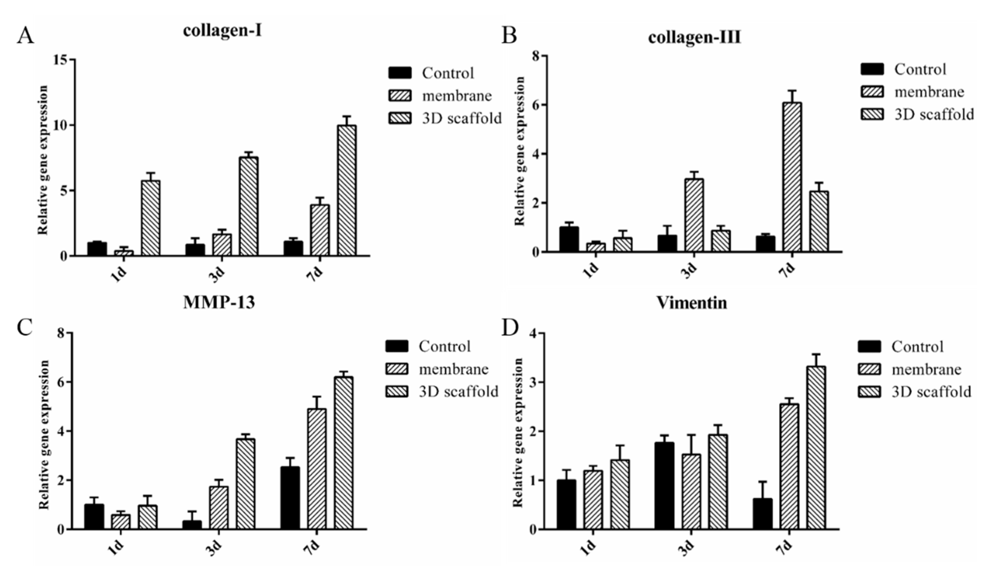
In order to confirm that 3D nanofibrous scaffolds are suitable for cell proliferation and infiltration, and to understand the cellular behaviors in seeded scaffolds, the expression levels of the associated genes were determined by RT-PCR. The gene expression levels were found increased along with the culturing time (Figure 7). The expression of collagen I remained much higher in the 3D nanofibrous scaffold groups compared to the electrospun membranes. In contrast, the expression of collagen type III was much higher in the electrospun membranes groups. Since collagen I is the predominant collagen and maintains cellular integrity by providing mechanical strength, while collagen III is abundant in tissues having elastic properties [41], the current results confirmed that 3D scaffolds with porous structures could provide a mechanical stable environment, which accelerated the ECM deposition from the seeded fibroblasts [42]. Meanwhile, the expression of collagen I was found to be relatively higher than that of collagen III in both 3D scaffolds and membranes. A possible explanation is that these samples are rich in RHC; thus, there is no need to produce much of their own collagen III during the culture. The expression of MMP-13 was detected in our study, as it acts as a kind of collagenase in cellular activates. Following an injury, MMP facilitates the removal of degraded ECM components in a wound and reorganizes the provisional matrix for efficient cell migration; then, it accelerates the wound healing [43]. Similar to collagen I, MMP-13 showed higher expression levels in the 3D nanofibrous scaffolds, revealing a more effective migration of NIH 3T3 [44]. The expression of vimentin, a guarantee of fibroblast proliferation and coordinated in collagen accumulation, increased with culture time, and this value was also higher for the 3D nanofibrous scaffold groups throughout the experiments. All these results proved that the 3D nanofibrous scaffolds are capable of supporting cell migration and proliferation.
4. Conclusions
In this study, electrospinning and freeze-drying techniques were combined to produce 3D nanofibrous scaffolds with porous structures, and the fabricated scaffolds were further crosslinked by EDC. Morphology study illustrated the scaffold owned interconnected porous structures with the presenting of nanofibers, and the porosities of the scaffolds were found independent to the adding of nanofibers. The mechanical strengths of the porous scaffolds can be tuned by nanofibers or chitosan/RHC concentration. Specifically, increasing the number of nanofibers led to an increase in the mechanical strength of the scaffolds. The cell viability test determined that the fabricated 3D scaffolds are non-toxic to the selected cells. Meanwhile, cell distribution proved that nanofibrous porous structures facilitated the spreading and migration of the proliferated cells as cells infiltrated into the inner part of the scaffolds from day 3 to 7. Results from RT-PCR further confirmed that nanofibrous scaffolds could support the cell attachment, proliferation, and migration as the expressions of ECM-associated proteins were unregulated by the 3D scaffolds. Thus, the fabricated 3D nanofibrous scaffold shows it potentials in tissue engineering application and tissue regeneration.
Author Contributions
Conceptualization, A.D. and Y.Y.; methodology, A.D. and S.D.; formal analysis, S.D.; investigation, A.D. and Y.Y.; writing—original draft preparation, A.D.; writing—review and editing, Y.Y.; visualization, Y.Y.; supervision, Y.Y. All authors have read and agreed to the published version of the manuscript.
Funding
This research was funded by the National High Technology Research and Development Program of China (No. 2014AA022107).
Institutional Review Board Statement
Not applicable (This study does not involve human or animal).
Informed Consent Statement
Not applicable.
Data Availability Statement
This study did not report any data.
Acknowledgments
This work was financially supported by the National High Technology Research and Development Program of China (No. 2014AA022107), and the Priority Academic Program Development of Jiangsu Higher Education Institutions (PAPD).
Conflicts of Interest
There is no conflict of interest.
References
- Li, M.; Khadim, R.R.; Nagayama, M.; Shinohara, M.; Inamura, K.; Danoy, M.; Nishikawa, M.; Furukawa, K.; Sakai, Y.; Niino, T. Fabrication of a Porous Three-Dimensional Scaffold with Interconnected Flow Channels: Co-Cultured Liver Cells and In Vitro Hemocompatibility Assessment. Appl. Sci. 2021, 11, 2473. [Google Scholar] [CrossRef]
- Yao, Q.Q.; Cosme, J.G.L.; Xu, T.; Miszuk, J.M.; Picciani, P.H.S.; Fong, H.; Sun, H.L. Three dimensional electrospun PCL/PLA blend nanofibrous scaffolds with significantly improved stem cells osteogenic differentiation and cranial bone formation. Biomaterials 2017, 115, 115–127. [Google Scholar] [CrossRef] [Green Version]
- Dhandayuthapani, B.; Yoshida, Y.; Maekawa, T.; Kumar, D.S. Polymeric Scaffolds in Tissue Engineering Application: A Review. Int. J. Polym. Sci. 2011. [Google Scholar] [CrossRef]
- Wang, X.; Ding, B.; Li, B. Biomimetic electrospun nanofibrous structures for tissue engineering. Mater. Today 2013, 16, 229–241. [Google Scholar] [CrossRef] [PubMed]
- Kalsi, S.; Singh, J.; Sehgal, S.S.; Sharma, N.K. Biomaterials for tissue engineered bone Scaffolds: A review. Mater. Today Proc. 2021. [Google Scholar] [CrossRef]
- Mao, Y.; Guidoin, R.; Li, Y.; Brochu, G.; Zhang, Z.; Wang, L. Soybean-derived phospholipids complexed poly (lactic-co-glycolic acid) nanofibrous scaffolds for tissue engineering applications. Mater. Des. 2021, 205, 109737. [Google Scholar] [CrossRef]
- Ding, Y.; Li, W.; Schubert, D.W.; Boccaccini, A.R.; Roether, J.A.; Santos, H.A. An organic-inorganic hybrid scaffold with honeycomb-like structures enabled by one-step self-assembly-driven electrospinning. Mater. Sci. Eng. C 2021, 124, 112079. [Google Scholar] [CrossRef] [PubMed]
- Bandegi, A.; Moghbeli, M.R. Effect of solvent quality and humidity on the porous formation and oil absorbency of SAN electrospun nanofibers. J. Appl. Polym. Sci. 2018, 135, 45586. [Google Scholar] [CrossRef]
- Bhowmick, S.; Scharnweber, D.; Koul, V. Co-cultivation of keratinocyte-human mesenchymal stem cell (hMSC) on sericin loaded electrospun nanofibrous composite scaffold (cationic gelatin/hyaluronan/chondroitin sulfate) stimulates epithelial differentiation in hMSCs: In vitro study. Biomaterials 2016, 88, 83–96. [Google Scholar] [CrossRef]
- Zhao, Q.; Zhou, Y.; Wang, M. Three-dimensional endothelial cell incorporation within bioactive nanofibrous scaffolds through concurrent emulsion electrospinning and coaxial cell electrospraying. Acta Biomater. 2021, 123, 312–324. [Google Scholar] [CrossRef]
- Al-Kaabi, W.J.; Albukhaty, S.; Al-Fartos, Y.A.; Al-Karagoly, H.K.; Soliman, D.A. Development of Inula graveolens (L.) Plant Extract Electrospun/Polycaprolactone Nanofibers: A Novel Material for Biomedical Application. Appl. Sci. 2021, 11, 828. [Google Scholar] [CrossRef]
- Chen, H.; Peng, Y.; Wu, S.; Tan, L. Electrospun 3D Fibrous Scaffolds for Chronic Wound Repair. Materials 2016, 9, 272. [Google Scholar] [CrossRef] [PubMed] [Green Version]
- Mahjour, S.B.; Sefat, F.; Polunin, Y.; Wang, L.C.; Wang, H.J. Improved cell infiltration of electrospun nanofiber mats for layered tissue constructs. J. Biomed. Mater. Res. Part A 2016, 104, 1479–1488. [Google Scholar] [CrossRef] [Green Version]
- Ameer, J.M.; Pr, A.K.; Kasoju, N. Strategies to Tune Electrospun Scaffold Porosity for Effective Cell Response in Tissue Engineering. J. Funct. Biomater. 2019, 10, 30. [Google Scholar] [CrossRef] [Green Version]
- Aghajanpoor, M.; Hashemi-Najafabadi, S.; Baghaban-Eslaminejad, M.; Bagheri, F.; Mousavi, S.M.; Sayyahpour, F.A. The effect of increasing the pore size of nanofibrous scaffolds on the osteogenic cell culture using a combination of sacrificial agent electrospinning and ultrasonication. J. Biomed. Mater. Res. Part A 2017, 105, 1887–1899. [Google Scholar] [CrossRef]
- Tornello, P.; Caracciolo, P.C.; Rosello, J.I.I.; Abraham, G.A. Electrospun scaffolds with enlarged pore size: Porosimetry analysis. Mater. Lett. 2018, 227, 191–193. [Google Scholar] [CrossRef]
- Gupte, M.J.; Swanson, W.B.; Hu, J.; Jin, X.; Ma, H.; Zhang, Z.; Liu, Z.; Feng, K.; Feng, G.; Xiao, G. Pore Size Directs Bone Marrow Stromal Cell Fate and Tissue Regeneration in Nanofibrous Macroporous Scaffolds by Mediating Vascularization. Acta Biomater. 2018, 82, 1–11. [Google Scholar] [CrossRef] [PubMed]
- Zhang, J.; Zhou, A.; Deng, A.; Yang, Y.; Gao, L.; Zhong, Z.; Yang, S. Pore architecture and cell viability on freeze dried 3D recombinant human collagen-peptide (RHC)–chitosan scaffolds. Mater. Sci. Eng. C 2015, 49, 174–182. [Google Scholar] [CrossRef] [PubMed]
- Chen, Z.; Yan, X.; Yin, S.; Liu, L.; Liu, X.; Zhao, G.; Ma, W.; Qi, W.; Ren, Z.; Liao, H.; et al. Influence of the pore size and porosity of selective laser melted Ti6Al4V ELI porous scaffold on cell proliferation, osteogenesis and bone ingrowth. Mater. Sci. Eng. C 2020, 106, 110289. [Google Scholar] [CrossRef]
- Mochane, M.J.; Motsoeneng, T.S.; Sadiku, E.R.; Mokhena, T.C.; Sefadi, J.S. Morphology and Properties of Electrospun PCL and Its Composites for Medical Applications: A Mini Review. Appl. Sci. 2019, 9, 2205. [Google Scholar] [CrossRef] [Green Version]
- Zarei, M.; Samimi, A.; Khorram, M.; Abdi, M.M.; Golestaneh, S.I. Fabrication and characterization of conductive polypyrrole/chitosan/collagen electrospun nanofiber scaffold for tissue engineering application. Int. J. Biol. Macromol. 2021, 168, 175–186. [Google Scholar] [CrossRef] [PubMed]
- Korpayev, S.; Kaygusuz, G.; En, M.; Orhan, K.; Karakeili, A. Chitosan/collagen based biomimetic osteochondral tissue constructs: A growth factor-free approach. Int. J. Biol. Macromol. 2020, 156, 681–690. [Google Scholar] [CrossRef]
- Yang, Y.; Campbell Ritchie, A.; Everitt, N.M. Recombinant human collagen/chitosan-based soft hydrogels as biomaterials for soft tissue engineering. Mater. Sci. Eng. C 2021, 121, 111846. [Google Scholar] [CrossRef] [PubMed]
- Suo, H.; Zhang, J.; Xu, M.; Wang, L. Low-temperature 3D printing of collagen and chitosan composite for tissue engineering. Mater. Sci. Eng. C 2021, 123, 111963. [Google Scholar] [CrossRef]
- Anderson, J.M.; Rodriguez, A.; Chang, D.T. Foreign body reaction to biomaterials. Semin. Immunol. 2008, 20, 86–100. [Google Scholar] [CrossRef] [Green Version]
- Fertala, A. Three Decades of Research on Recombinant Collagens: Reinventing the Wheel or Developing New Biomedical Products? Bioengineering 2020, 7, 155. [Google Scholar] [CrossRef]
- Deng, A.; Yang, Y.; Shimei, D.; Shulin, Y. Electrospinning of in situ crosslinked recombinant human collagen peptide/chitosan nanofibers for wound healing. Biomater. Sci. 2018, 6, 2197–2208. [Google Scholar] [CrossRef]
- Liu, B.; Lei, Y.T.; Zhang, J.; Hu, L.; Yang, S.L. Expression, Purification and Characterization of Recombinant Human Gelatin in Pichia pastoris. Adv. Mater. Res. 2011, 236–238, 2905–2912. [Google Scholar] [CrossRef]
- Oh, S.H.; Park, I.K.; Kim, J.M.; Lee, J.H. In vitro and in vivo characteristics of PCL scaffolds with pore size gradient fabricated by a centrifugation method. Biomaterials 2007, 28, 1664–1671. [Google Scholar] [CrossRef]
- Nam, K.; Kimura, T.; Kishida, A. Controlling Coupling Reaction of EDC and NHS for Preparation of Collagen Gels Using Ethanol/Water Co-Solvents. Macromol. Biosci. 2007, 8, 32–37. [Google Scholar] [CrossRef] [PubMed]
- Liu, M.X.; Shen, Y.; Ao, P.; Dai, L.B.; Liu, Z.H.; Zhou, C.R. The improvement of hemostatic and wound healing property of chitosan by halloysite nanotubes. RSC Adv. 2014, 4, 23540–23553. [Google Scholar] [CrossRef]
- Gao, X.; Qin, W.; Wang, P.; Wang, L.; Weir, M.D.; Reynolds, M.A.; Zhao, L.; Lin, Z.; Xu, H.H.K. Nano-Structured Demineralized Human Dentin Matrix to Enhance Bone and Dental Repair and Regeneration. Appl. Sci. 2019, 9, 1013. [Google Scholar] [CrossRef] [Green Version]
- Winter, G.D. Transcutaneous implants: Reactions of the skin-implant interface. J. Biomed. Mater. Res. 1974, 8, 99–113. [Google Scholar] [CrossRef]
- Chen, W.M.; Ma, J.; Zhu, L.; Morsi, Y.; Ei-Hamshary, H.; Al-Deyab, S.S.; Mo, X.M. Superelastic, superabsorbent and 3D nanofiber-assembled scaffold for tissue engineering. Colloids Surf. B-Biointerfaces 2016, 142, 165–172. [Google Scholar] [CrossRef]
- Zhang, L.; Liu, X.; Li, G.; Wang, P.; Yang, Y. Tailoring degradation rates of silk fibroin scaffolds for tissue engineering. J. Biomed. Mater. Res. Part A 2019, 107, 104–113. [Google Scholar] [CrossRef] [PubMed] [Green Version]
- Staroszczyk, H.; Sztuka, K.; Wolska, J.; Wojtasz-Pająk, A.; Kołodziejska, I. Interactions of fish gelatin and chitosan in uncrosslinked and crosslinked with EDC films: FT-IR study. Spectrochim. Acta Part A Mol. Biomol. Spectrosc. 2014, 117, 707–712. [Google Scholar] [CrossRef]
- Harley, B.A.; Leung, J.H.; Silva, E.C.C.M.; Gibson, L.J. Mechanical characterization of collagen–glycosaminoglycan scaffolds. Acta Biomater. 2007, 3, 463–474. [Google Scholar] [CrossRef] [PubMed]
- Yang, Y.; Ritchie, A.C.; Everitt, N.M. Comparison of glutaraldehyde and procyanidin cross-linked scaffolds for soft tissue engineering. Mater. Sci. Eng. C 2017, 80, 263–273. [Google Scholar] [CrossRef]
- Alberti, T.B.; Coelho, D.S.; Pra, M.; Maraschin, M.; Veleirinho, B. Electrospun PVA nanoscaffolds associated with propolis nanoparticles with wound healing activity. J. Mater. Sci. 2020, 55, 9712–9727. [Google Scholar] [CrossRef]
- Naskar, D.; Ghosh, A.K.; Mandal, M.; Das, P.; Nandi, S.K.; Kundu, S.C. Dual growth factor loaded nonmulberry silk fibroin/carbon nanofiber composite 3D scaffolds for in vitro and in vivo bone regeneration. Biomaterials 2017, 136, 67–85. [Google Scholar] [CrossRef]
- Ryoo, S.R.; Kim, Y.K.; Kim, M.H.; Min, D.H. Behaviors of NIH-3T3 Fibroblasts on Graphene/Carbon Nanotubes: Proliferation, Focal Adhesion, and Gene Transfection Studies. ACS Nano 2010, 4, 6587–6598. [Google Scholar] [CrossRef] [PubMed]
- Zubair, A.R.; Shahrom, A.W.; Swarhib, M.; Nurliza, A. Determination of age of skin wound by measuring collagen type I and III using picrosirius polarization method. Int. J. Med. Toxicol. Leg. Med. 2018, 21, 1. [Google Scholar] [CrossRef]
- Nguyen, T.T.; Wolter, W.R.; Anderson, B.; Schroeder, V.A.; Gao, M.; Gooyit, M.; Suckow, M.A.; Chang, M. Limitations of Knockout Mice and Other Tools in Assessment of the Involvement of Matrix Metalloproteinases in Wound Healing and the Means to Overcome Them. ACS Pharmacol. Transl. Sci. 2020, 3, 489–495. [Google Scholar] [CrossRef] [PubMed] [Green Version]
- Sarkar, S.D.; Farrugia, B.L.; Dargaville, T.R.; Dhara, S. Chitosan-collagen scaffolds with nano/microfibrous architecture for skin tissue engineering. J. Biomed. Mater. Res. Part A 2013, 101, 3482–3492. [Google Scholar] [CrossRef] [PubMed] [Green Version]
Figure 1.
Structure of the electrospinning nanofibers and short nanofibers. (A) SEM image of the electrospun nanofibers. (B) Diameter distribution of the electrospun nanofibers. (C) SEM image of the homogenized short nanofibers. (D) Diameter distribution of the homogenized short nanofibers.
Figure 1.
Structure of the electrospinning nanofibers and short nanofibers. (A) SEM image of the electrospun nanofibers. (B) Diameter distribution of the electrospun nanofibers. (C) SEM image of the homogenized short nanofibers. (D) Diameter distribution of the homogenized short nanofibers.
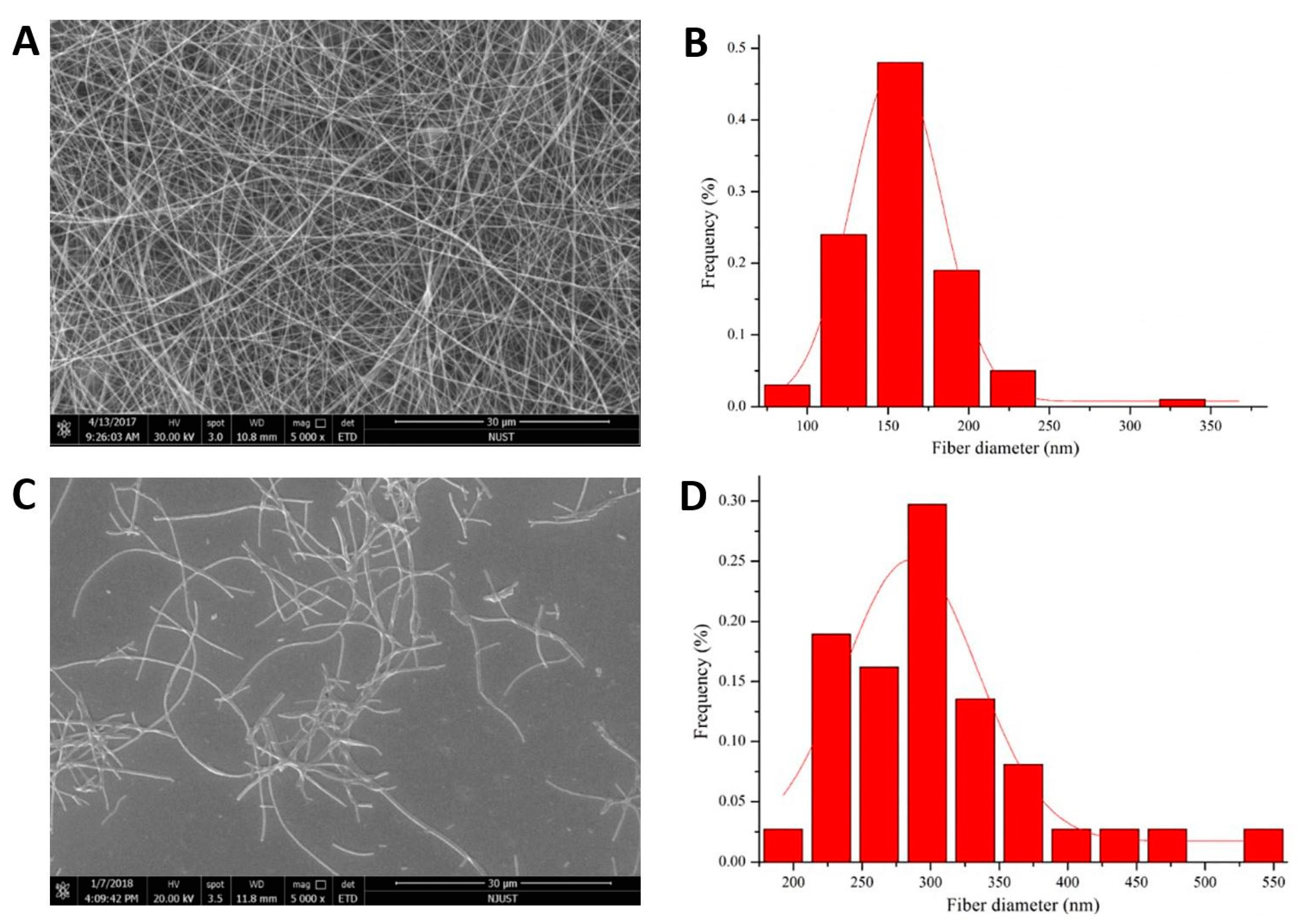
Figure 2.
SEM images of the 3D nanofibrous scaffolds. (a–d) Scaffolds of 1%-0.5 mL, 1%-1 mL, 2%-1 mL, and 1%-0 mL at 500×. (A–D) Scaffolds of 1%-0.5 mL, 1%-1 mL, 2%-1 mL, and 1%-0 mL at 5000×.
Figure 2.
SEM images of the 3D nanofibrous scaffolds. (a–d) Scaffolds of 1%-0.5 mL, 1%-1 mL, 2%-1 mL, and 1%-0 mL at 500×. (A–D) Scaffolds of 1%-0.5 mL, 1%-1 mL, 2%-1 mL, and 1%-0 mL at 5000×.
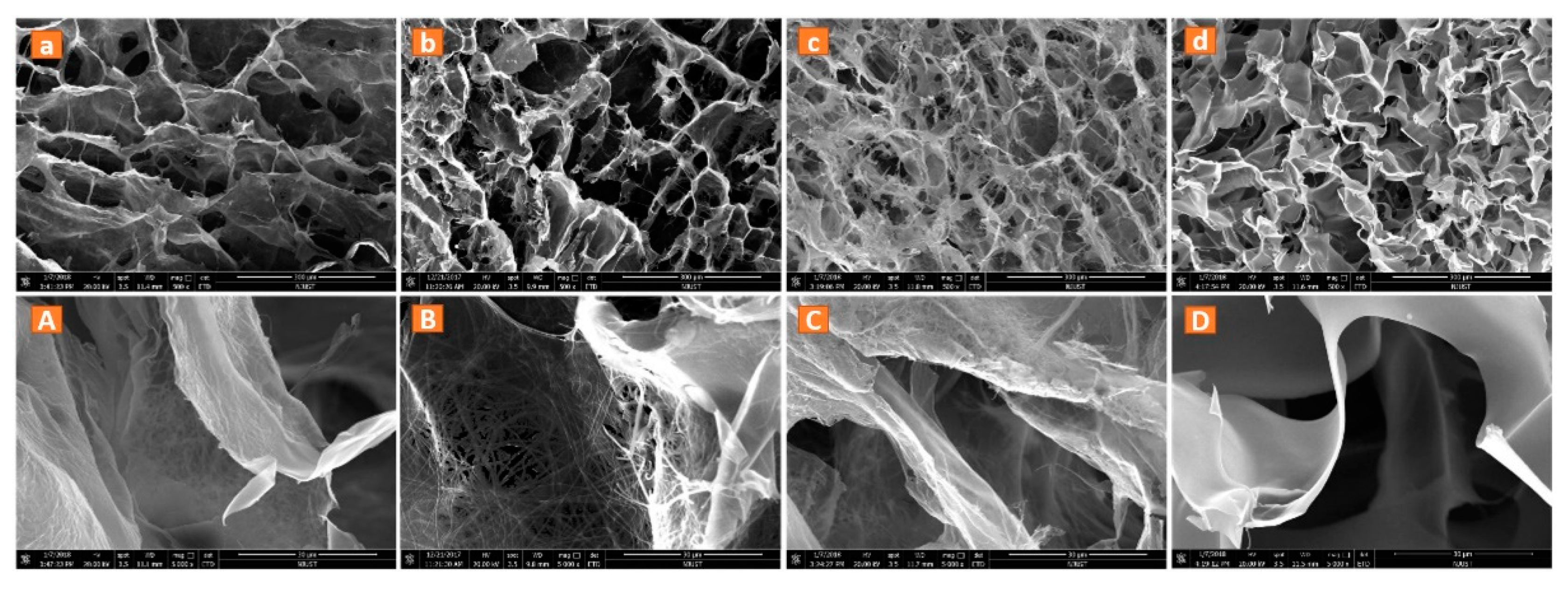
Figure 3.
Characterization of the different scaffolds. (A) Porosity. (B) Swelling ability. (C) Degradation rate in a lysozyme solution. (D) Spectra obtained from RHC and 3D nanofibrous scaffold in FT-IR tests. * p < 0.05, *** p < 0.001, compared with pure chitosan/RHC scaffold, ## p < 0.01. Bars represent mean ±SD, number of repeats n = 3.

Figure 4.
Mechanical tests of the different scaffolds. (A) Stress–strain curves of the scaffolds; (B) compression modulus of 3D nanofibrous scaffolds. * p < 0.05 and *** p < 0.001, compared with pure chitosan/RHC scaffold (1%-0 mL), # p < 0.05. Bars represent mean ± SD, number of repeats n = 5.
Figure 4.
Mechanical tests of the different scaffolds. (A) Stress–strain curves of the scaffolds; (B) compression modulus of 3D nanofibrous scaffolds. * p < 0.05 and *** p < 0.001, compared with pure chitosan/RHC scaffold (1%-0 mL), # p < 0.05. Bars represent mean ± SD, number of repeats n = 5.

Figure 5.
NIH 3T3 cells proliferation tests on different 3D nanofibrous scaffolds and membrane at culturing day 1, 3 and 7 by MTT assay. * p < 0.05, compared with pure chitosan/RHC nanofibrous membrane. Bars represent mean ± SD, number of repeats n = 3.
Figure 5.
NIH 3T3 cells proliferation tests on different 3D nanofibrous scaffolds and membrane at culturing day 1, 3 and 7 by MTT assay. * p < 0.05, compared with pure chitosan/RHC nanofibrous membrane. Bars represent mean ± SD, number of repeats n = 3.

Figure 6.
AO/EB double fluorescence staining of NIH 3T3 cultured on 3D nanofibrous scaffolds. (A–C) Images of the transversal section after 1, 3, and 7 days with 10× objective lens. (D–F) Images with 20× objective lens corresponding to (A–C). (G–I) Vertical sections corresponding to (A–C). The red dotted lines represent the surface of the scaffolds.

Figure 7.
Expression of: (A) collagen I, (B) collagen III, (C) MMP-13, and (D) vimentin in nanofibrous membranes, 3D nanofibrous scaffolds and culture dishes as measured by RT-PCR. Bars represent mean ± SD, number of repeats n = 3.
Figure 7.
Expression of: (A) collagen I, (B) collagen III, (C) MMP-13, and (D) vimentin in nanofibrous membranes, 3D nanofibrous scaffolds and culture dishes as measured by RT-PCR. Bars represent mean ± SD, number of repeats n = 3.
Publisher’s Note: MDPI stays neutral with regard to jurisdictional claims in published maps and institutional affiliations. |
© 2021 by the authors. Licensee MDPI, Basel, Switzerland. This article is an open access article distributed under the terms and conditions of the Creative Commons Attribution (CC BY) license (https://creativecommons.org/licenses/by/4.0/).
Share and Cite
MDPI and ACS Style
Deng, A.; Yang, Y.; Du, S. Tissue Engineering 3D Porous Scaffolds Prepared from Electrospun Recombinant Human Collagen (RHC) Polypeptides/Chitosan Nanofibers. Appl. Sci. 2021, 11, 5096. https://doi.org/10.3390/app11115096
AMA Style
Deng A, Yang Y, Du S. Tissue Engineering 3D Porous Scaffolds Prepared from Electrospun Recombinant Human Collagen (RHC) Polypeptides/Chitosan Nanofibers. Applied Sciences. 2021; 11(11):5096. https://doi.org/10.3390/app11115096
Chicago/Turabian StyleDeng, Aipeng, Yang Yang, and Shimei Du. 2021. "Tissue Engineering 3D Porous Scaffolds Prepared from Electrospun Recombinant Human Collagen (RHC) Polypeptides/Chitosan Nanofibers" Applied Sciences 11, no. 11: 5096. https://doi.org/10.3390/app11115096
Note that from the first issue of 2016, this journal uses article numbers instead of page numbers. See further details here.