Article

Numerical Simulation of Intrachamber Processes in the Power Plant

1
Department of Heat Engines and Plants, Faculty of Mechanical Engineering, Kalashnikov Izhevsk State Technical University, 7, Studencheskaya Str., 426069 Izhevsk, Russia
2
Department of Applied Mechanics and Mechanical Engineering, Faculty of Mechanical Engineering, Technical University of Košice, Letná 9, 040 02 Košice, Slovakia
*
Author to whom correspondence should be addressed.
Appl. Sci. 2021, 11(11), 4990; https://doi.org/10.3390/app11114990
Submission received: 29 April 2021 / Revised: 25 May 2021 / Accepted: 26 May 2021 / Published: 28 May 2021
(This article belongs to the Special Issue Trends in Modeling and Simulation of Production Processes and Systems)

Abstract

:
This paper considers the issues of numerical modeling of nonstationary spatial gas dynamics in the pre-nozzle volume of the combustion chamber of a power plant with a cylindrical slot channel at the power plant of the mass supply surface. The numerical simulation for spatial objects is based on the solution conjugate problem of heat exchange by the control volume method in the open integrated platform for numerical simulation of continuum mechanics problems (openFoam). The calculation results for gas-dynamic and thermal processes in the power plant with a four-nozzle cover are presented. The analysis of gas-dynamic parameters and thermal flows near the nozzle cover, depending on the canal geometry, is given. The topological features of the flow structure and thermophysical parameters near the nozzle cap were studied. For the first time, the transformation of topological features of the flow structure in the pre-nozzle volume at changes in the mass channel’s geometry is revealed, described, and analyzed. The dependence of the Nusselt number in the central point of stagnation on the time of the power plants operation is revealed.

1. Introduction

At present, despite the high level and widespread use of mathematical modeling methods, there are no data on the assessment of unsteady heat exchanges of complex three-dimensional flows in the flow paths of power plants. At the same time, the relationship of the flow structure in such devices with a local unsteady heat exchange is practically not studied.
It should be noted that, in the case of the process unsteadiness, the transitions between unstable topological features are associated with nonstationary oscillations of flows, which may cause changes in flow characteristics and frequency disturbances. That is, they can lead to abnormal operating modes of such devices. Therefore, a unified approach from a topological point of view is needed to assess such phenomena for three-dimensional flows in the channels of power plants.
The functioning of power plants (PP) is associated with intensive heat emission processes. It should be noted that the modern trend of mechanical engineering development requires further mass minimization for power plants and the optimization of working processes in the combustion chamber of the power plant (CC PP). At the same time, a number of PP does not imply using heat exchange devices [1,2,3], which demands the development of special heat-protective coatings [4,5]. The choice of heat-protective coatings [5] requires an evaluation of their thickness and thermal resistance [6,7] that depend on the intensity of heat fluxes in the CC PP. To assess the heat flux intensity correctly [5,6,7,8,9], it is necessary to consider the design features of the CC PP.
The application of engineering methods for analyzing heat fluxes in CC PP is widespread. In practice, the formulas of Kraussold and Eckert [7,8,9] are usually used [4,5,6,7,8,9], which are obtained experimentally and valid for turbulent gas/liquid flows in tubes of a considerable length and for the plate flow-around. These criteria dependencies do not allow taking into account the spatiality of flows implemented in CC; as shown in [10], their application leads to the incorrect assessment of heat fluxes.
In modern works, the issues of studying the heat exchange processes taking place in the flow paths and pre-nozzle volume (PV) of the power plant combustion chamber are insufficiently considered. Certain works on experimental studying of the heat exchange can be highlighted [11,12,13]. Still, the application of the obtained results for PP designing is difficult due to the absence of generalized engineer regularities, which are valid for various types of PP (for example, universal criterion equations), or because of the unstudied range of applicability for the derived relations.
Mathematical modeling of intrachamber processes in a power plant is considered in [14,15,16,17,18,19,20,21]. However, they lack practically useful criteria equations. In [13,14,15,16,17,18,19,20], it is shown that the spatial flow in the CC and PV is characterized by the presence of vortex structures. Heat exchange processes in different layouts of PP are studied in [15,16,17], but they do not provide criteria relations, and there is no assessment of the applicability for equations [1,2,3,4,5,6,7]. The study of heat transfer in the CC PP in the one-dimensional statement is carried out in [14], but there is no assessment of the adequacy of the obtained results as applied to spatial objects.
The application of mathematical modeling methods to study the heat exchange processes in individual structures of PP is considered in [10,11,12,13,14,15,16,17,18,19,20]. In [10,11,12,13,14,15,18,19,20,22], the features of the flow structure in the pre-nozzle volume of CC PP with a recessed nozzle are shown, but there are no assessments of heat exchange near the surface of the recessed nozzle. Heat exchange processes in CC for various PP layouts are studied in [10,12,21,22,23]. The study of gas dynamics in one-dimensional statement and heat exchange in CC of power plants was performed in [24]. However, in [24], the questions of application of the results obtained in the framework of the one-dimensional approach to the evaluation of heat exchange of spatial flows were not investigated.
In the PP operation, the geometry of the mass supply channel is changed, which leads to rearrangement of the gas flow in flow paths of the CC PP. The influence of changes in the mass supply channel geometry during the PP operation on gas dynamic and thermophysical processes in the combustion chamber is not considered in the literature. Thus, the work aims to study unsteady intrachamber processes taking place in CC PP with the account of the motion of the mass supply surface.

2. Materials and Methods

2.1. Problem Statement and Mathematical Model

The conjugate problem of heat exchange in CC PP with a cylindrical slot channel and a four-nozzle cover (Figure 1) is considered.
The turbulent spatial flow of the compressed heat-conducting gas is described by the following system of conservation equations [23]:
ρ t + ρ u i x i = 0
ρ u i t + ρ u i u j x j = p x i + x j ( μ ( u i x j + u j x i ) 2 3 μ u k x k δ i j ) + F i
ρ E t + ρ E u j x j = p u j x j + u i τ i j x j + q j x j + F i u i
c ρ T t = λ 2 T ,
p = ρ R T
where ρ is the gas density, p is the pressure, u i is the velocity components, F i is the external volume force, T is the temperature, q j is the component of heat flow density vector, R is the specific gas constant; µ is the dynamic viscosity, λ is the heat conductivity factor, E = c ν T + 0.5 u i 2 is the total specific energy, G = E + p / ρ = c p T + 0.5 u i 2 = h + 0.5 u i 2 is the total specific enthalpy; τ i j = 2 μ S i j 2 3 μ u k x k δ i j is the viscous stress tensor; S i j = 1 2 ( u i x j + u j x i ) is the strain velocity tensor.
In the literature, there is no substantiation for the application of turbulence models for flows in the flow paths of the combustion chamber of the power plant, and there is no experimental confirmation of the model correctness. As a consequence, the implementation of the mode with a significant difference in the transfer of individual components of the Reynolds stress tensor based on the analysis of physical models for the flow in flow paths of PP was taken into account. Initial equations are averaged accordingly [25], values are given as a sum θ = θ ˜ + θ , where θ ˜ = ρ θ ¯ / ρ ¯ and ρ θ ¯ , ρ ¯ are the averaged parameters according to the Reynolds procedure. Thus, θ includes both turbulent and density fluctuation. It is the most appropriate [25,26,27,28] to apply the model of the Reynolds stress component transfer within the Mentor model [29]:
ρ ¯ t + ρ ¯ u ˜ i x i = 0 ,
ρ ¯ u ˜ i t + ρ ¯ u ˜ i u ˜ j x j = p ¯ x i + x j ( τ ˜ i j + τ ˜ t i j ) + F ¯ i ,
ρ ¯ E ˜ t + ρ ¯ E ˜ u ˜ j x j = p ¯ u ˜ j x j + x j [ u ˜ i ( τ ˜ i j + τ ˜ t i j ) ] + x j ( q ¯ j + q ¯ t j ) + F ¯ j u ˜ j ,
p ¯ = ρ ¯ R T ˜
In Equations (6)–(9), the following designations are taken:
τ ˜ i j = μ ( u ˜ i x j + u ˜ j x i ) 2 3 μ u ˜ k x k δ i j ,
τ ˜ t i j = ρ u i u u ¯ = μ t ( u ˜ i x j + u ˜ j x i 2 3 u ˜ k x k δ i j ) 2 3 k ρ ¯ δ i j ,
μ t = ρ ¯ ν t ,
k = ρ u i u i ¯ 2 ρ ¯ ,
ε = c μ k ω ,
q t j = ρ u i h ¯ , ,
where τ ˜ i j is the Favre averaged viscous stress tensor, τ ˜ t i j is the Favre averaged turbulent stress tensor, μ t is the dynamic coefficient of turbulent viscosity, k is the specific kinetic energy of turbulent motion, ω is the specific turbulent dissipation, ε is the turbulent dissipation and q t j is the turbulent heat flux.
The turbulent viscosity is calculated using the Shear Stress Transport (SST) turbulence model [16,25,26,29] in accordance with the following equations:
ρ ¯ k t + ρ ¯ k u ˜ j x j = P ˜ k β ρ ¯ k ω + x j [ ( μ + σ k μ t ) k x j ] ,
ρ ¯ ω t + ρ ¯ ω u ˜ j x j = 2 α ρ ¯ S i j S i j β ρ ¯ ω 2 + x j [ ( μ + σ ω μ t ) ω x j ] + 2 ( 1 F 1 ) ρ ¯ σ w 2 1 ω k x j ω x j ,
where
P k = μ t u i x j ( u i x j + u j x i ) P ˜ k = min ( P k , 10 β ρ ¯ k ω ) .
The coupling function is defined as
F 1 = tanh { min [ max ( k β ω y , 500 ν y 2 ω ) , 4 ρ ¯ σ ω 2 k C D k ω z 2 ] } 4 .
Here
C D k ω = max ( 2 ρ ¯ σ w 2 1 ω k x j ω x j , 10 10 ) ,
y is the distance to the nearest wall. The value F 1 is zero when it is far from solid boundaries (the k ε model is valid) and turns to the k ω model inside the boundary layer [2,25,26,29]. The turbulent viscosity coefficient is calculated by the formula:
μ t = ρ ¯ a 1 k max ( a 1 ω , 2 S i j S i j F 2 ) ,
where the second conjugation function F2 is defined as
F 2 = tanh { [ max ( 2 k β ω y , 500 ν y 2 ω ) ] 2 } .
All constants of the model in Equations (16) and (17) are calculated in accordance [2,25,26,29] with values from standard models k ε and k ω as α = α 1 F 1 + α 2 ( 1 F ) , etc. The constants of this model are β = 0.09 ,   α 1 = 5 / 9 ,   α 2 = 0.44 ,   β 1 = 3 / 40 ,   β 2 = 0.0828 , , σ k 1 = 0.85 ,   σ k 2 = 1 ,   σ ω 1 = 0.5 ,   σ ω 2 = 0.856 , and a1 = 0.31.
The working body is the combustion product of a conditional solid fuel with the adiabatic index k = c p / c v = 1.2 and the combustion temperature T = 2500 K. The temperature, pressure, and velocity of combustion products are assigned for mass supply surfaces, and non-reflective boundary conditions are set at the nozzle outlet. Conditions for adhesion and impermeability are assigned for solid impermeable surfaces. The boundary condition of the IVth type is set at the boundary of the solid and CP, and boundary conditions at outer boundaries are set in accordance with [26]. The motion of mass supply surfaces is assigned as their displacement velocity, as the function of pressure in CC.
Boundary conditions for (6–22) equation systems are given in Table 1.

2.2. Numerical Schemes and Algorithms

To approximate the equations of conservation (6–22) in space, the method of control volumes [1] was used. The partitioning of the calculated area in space was performed using prismatic elements (hexagons) with a total number of 1,480,000 elements [30]. Basic equations were discretized using a monotonic central difference scheme with the application of the PISO pressure correction algorithm and the Van-Lyre minmod limiter. As for orthogonal sections of the grid, the normal velocity gradients on the cell surface, required for the diffusion terms in calculating by Gauss theorem, are obtained from the velocity values at the centers of neighboring cells using a second-order scheme. An iterative procedure for error correction is used. An implicit Euler method is applied to discretize the time derivative. To solve the system of linear algebraic equations obtained during the discretization of equations, the iterative method of conjugate gradients with preconditioning for symmetric matrices is used, while for asymmetric matrices, it is the method of biconjugate gradients with preconditioning. For symmetric matrices, a procedure based on the simplified partial factorization scheme by Kholetsky was chosen as a preconditioner, while for asymmetric matrices, it was the preconditioner based on the simplified partial LU factorization scheme. Modeling was performed by means of computer simulation of gas dynamics and heat exchange processes in the open integrated platform for numerical simulation of continuum mechanics problems (openFoam) [31,32,33]. The visualization of the computation results was performed using the free software ParaView.
To verify the proposed numerical schemes and algorithms, the problem of gas flow in the flow paths of the four-nozzle model power plant [12,34,35,36,37,38,39,40,41,42] with a radial slot channel of the mass supply was solved. The calculated area is shown in Figure 1; the temperature, pressure, and gas velocity were assigned on the mass supply surfaces, non-reflective boundary conditions were set at the nozzle outlet, and adhesion and impermeability conditions were set on solid surfaces. The numerical experiment is described in detail in [20].
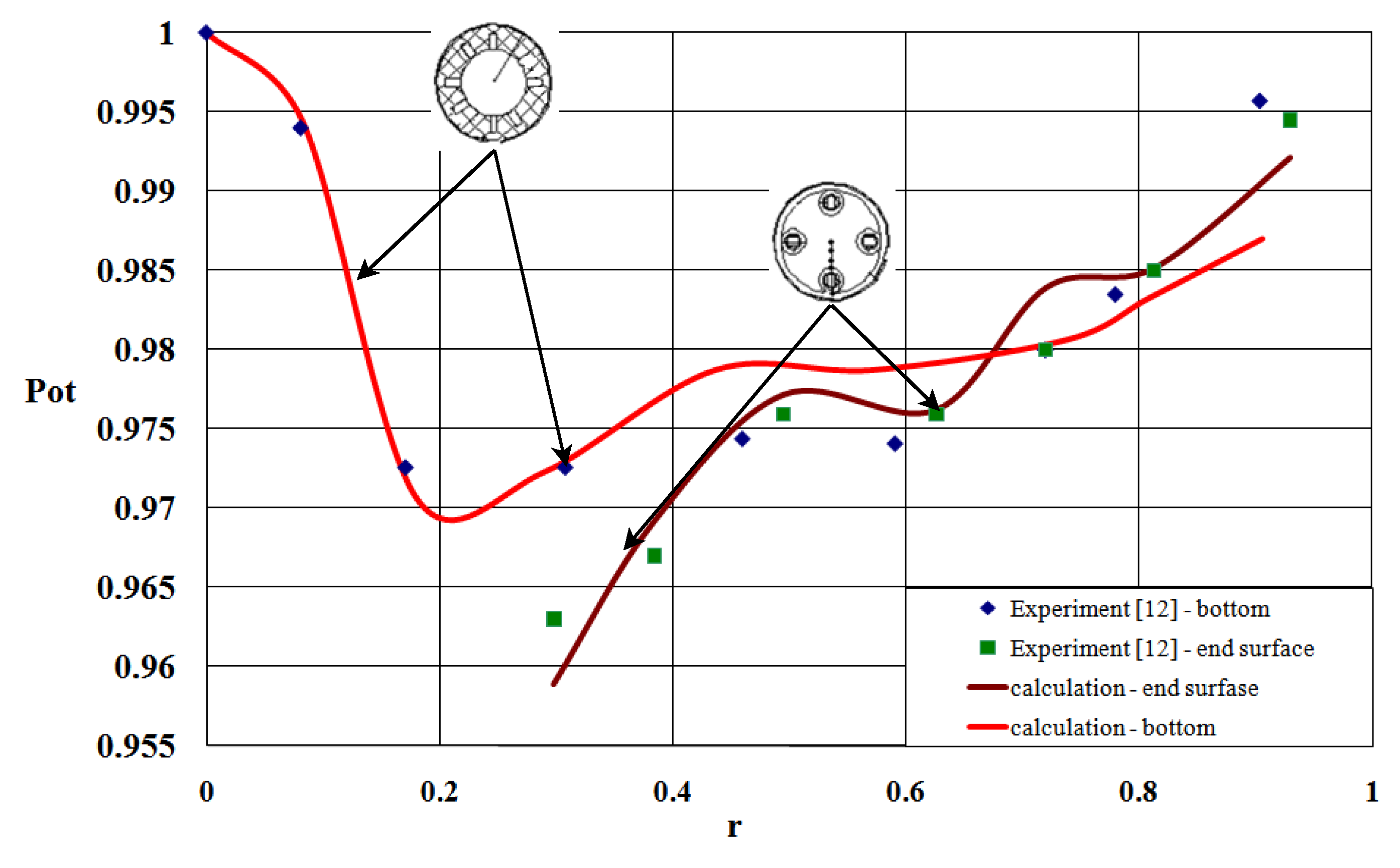
As a result of the calculated data analysis, pressure distribution over the nozzle bottom and the end surface is obtained (Figure 2). The arrangement of the experimental pressure sensors at the end face of the charge and the cover is schematically shown in the upper part of the figure, with arrows indicating which curve belongs to which experimental section.
A comparison of the calculated and experimental distributions of the relative pressure over the surface of the nozzle bottom and the end face of the slot charge (Figure 2) showed good qualitative and quantitative agreement between experimental and calculated data (except for the first and last points (relative error of 1.9% and 0.95%, respectively), the maximum relative error of the calculated data does not exceed 0.87%).

3. Results

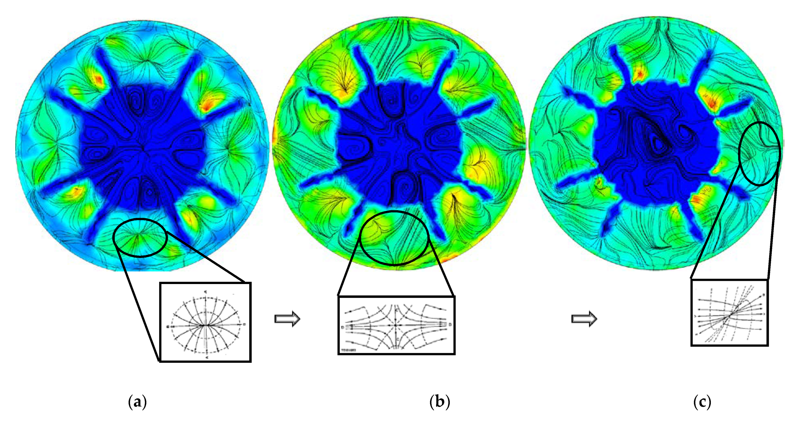
As a result of the calculations, instantaneous fields of physical quantities in the CC PP were obtained. The process of rearranging the flow structure near impermeable surfaces of PP was studied upon changing the geometry of the mass supply channel (Figure 3, black lines).
As shown in Figure 3 (black lines), an increase in the mass supply channel causes rearrangement of the flow structure near the nozzle bottom. However, regardless of the position of the mass supply boundaries on the nozzle cover, the formation of a central nodal point is revealed—the stagnation point, four radial flow-out lines coming from the nodal point, and eight peripheral flow-down lines; that is, the topological configuration of flows near the nozzle cover is invariant. At the same time, the rearrangement of the flow structure at the periphery of the cover between nozzles is noted. Thus, the rearrangement of reverse flows that are localized in the inter-nozzle part of the peripheral area of the pre-nozzle volume leads to the transformation of the singular point of the “unstable knot” type into a singular point of the “unstable focus” type with its subsequent periodic transformation (with the frequency 1 per 0.0003 s) into a singular point of the “saddle-focus” type and back into a point of the “unstable focus” type, which is associated with the formation of the separated flow near the nozzle entrance. Rearrangement of the flow is accompanied by an increase in the density of heat fluxes in the peripheral area of the PV, while after the formation of the separated zone in the area of the nozzle entrance, stabilization of heat fluxes near the nozzle cover is observed.
It should be noted that the change in the geometry of the mass supply channel also affects the structure of the flow near the impermeable end of the channel (Figure 4, black lines).
As shown in Figure 4, the movement of the mass supply boundaries leads to a rearrangement of the flow structure near the armored end of the channel. The flow symmetry violation in the inter-slot space is revealed. The central singular point of the “knot” type, which is typical for quasi-stationary modes [20], is transformed into a spatial configuration of the singular point of the “saddle” type with the subsequent transition to the “unstable knot”. In this case, the localization of singular points is shifted from the central area of the channel end to the channel periphery. This process is accompanied by a local increase in the intensity of heat fluxes (near singular points) with a decrease in heat flux values, which are integrated across the section.
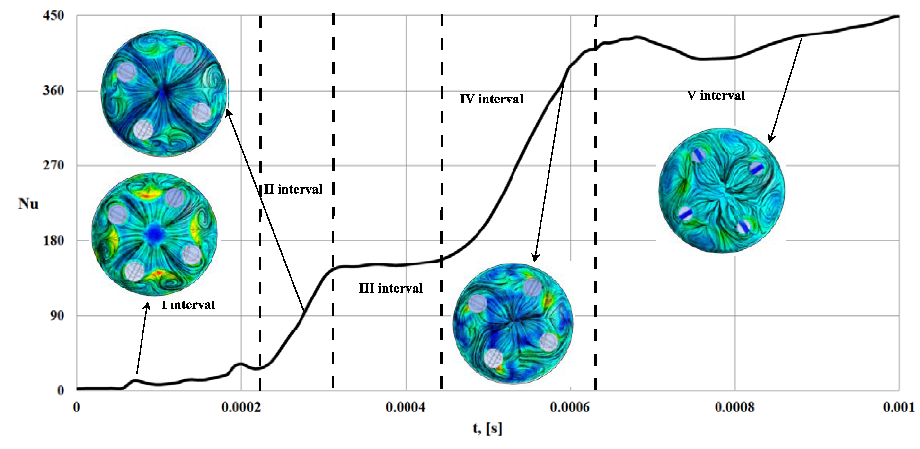
Analysis of the obtained data revealed the dependence of the Nusselt number in the central point of stagnation on the time of the PP operation and compared quasi-stationary sections of the obtained curve with the typical structures of the flow near the cover (Figure 5).
It should be noted that the structure of the limiting flow lines near the central nodal point is invariant to the shape of the geometry of the mass supply channel (Figure 3) and varies only slightly with the process time. On the graph of the change in the Nusselt number versus the time (Figure 5), we can distinguish intervals I, II, III and IV with a linear law of change in Nu(t). These intervals are characterized by the invariance of the flow structure (shown in Figure 5). Figure 5 shows that during the operation from 0 to 1 ms, the Nusselt number near the stagnation point increases by two orders of magnitude, which indicates an increase in the rate of heat exchange processes.

4. Discussion

This research is aimed at the energetical sector of machinery and its part power technology engines. The unsteady processes of the power plant operation are investigated when the geometry of the mass supply channels is changed. Changing the geometry of the mass supply channels in the radial direction leads to an increase in the mass supply surfaces and, as a consequence, to a change in the flow characteristics of the working gas. In view of this, to control the working processes of the PP, the study of the relationship between the shape of the PP channels, the realized modes of the flow (including topological features) and thermophysical processes are necessary.
The processes of transformation of the flow structure and the zones of increased heat exchange identified and described in the course of this study are characteristic not only for the considered time period. At the same time, the process of internal flow transformation is associated with a change in the energy characteristics of the flow and requires additional research. It was shown that the characteristic time of flow rearrangement is of the same order of magnitude as the change in the thermal state. It is advisable in further research to use the apparatus of the catastrophe theory for describing and predicting the transformation of singular zones and nodes on the impermeable surfaces of the PP when the geometry of the mass supply surface changes.
The flows described in this work are realized in such power plants as shell and tube heat exchangers, flow paths of nuclear reactors, various power plants and non-standard pressure injection and relief devices. That is, the flows described are characteristic of technical devices of power engineering, where complex three-dimensional flows of a higher-temperature continuum are realized. The approach to the study of nonstationary gas-dynamic and thermophysical processes proposed in this work has not been reported in the literature [42,43,44,45,46,47].
The paper brings several interesting benefits. One of the contributions of this work is that it shows the possibility of the numerical simulation method as an effective alternative to tests of power plants. The purpose, and also another benefit of the article, is receiving significantly more accurate results utilizing the conjugate solutions problem of heat exchange by control volume method in the open integrated platform for the numerical simulation of continuum mechanics problems (openFoam). The use of numerical simulation technologies at the design stage of power plants will significantly reduce the production cycle. Moreover, the transition from full-scale tests to computer simulations leads to a significant reduction in the cost of power plants.

5. Conclusions

The authors consider that the mathematical model of gas dynamics and heat exchange nonstationary spatial processes in flow paths of PP with the account of the movement of the mass supply surface is novel in this work. For the first time, the presence of several types of topological features arising from the interaction of a three-dimensional flow with solid surfaces of the flow paths of power plants was revealed, described and analyzed. The influence of the motion of the mass supply boundaries on the rearrangement of structure and the transformation of topological features is shown. A relationship was found between the location and type of topological features and the increase in the density of heat fluxes in them.
The quantitative estimate of the density of heat fluxes at singular points increases by a factor of nine, depending on the change in the radial size of the mass supply channel. For the first time, the time dependences of local dimensionless heat exchange coefficients in the vicinity of singular points and lines are obtained. Due to the lack of experimental data on unsteady heat exchange in the indicated areas (singular points and lines on impermeable surfaces), it is rather difficult to carry out a comparative analysis, despite the fact that a sufficiently detailed validation of the mathematical model was carried out. Time dependences of changes in local dimensionless heat exchange coefficients in the vicinity of singular points and lines near impermeable surfaces are obtained.

Author Contributions

Conceptualization, A.C.; methodology, B.B.; validation, A.C. and P.F. and B.B.; formal analysis, B.B. and P.F.; investigation, B.B.; writing: original draft preparation, A.C.; visualization, A.C.; supervision, P.F.; project administration, B.B., P.F. and A.C.; funding acquisition, P.F. All authors have read and agreed to the published version of the manuscript.

Funding

The research was carried out with the financial support of Kalashnikov ISTU within the framework of the scientific project No. ChAA/20-30-07. This research was funded by projects APVV-17-0258, KEGA 027TUKE-4/2020 and VEGA 1/0290/18.

Institutional Review Board Statement

Not applicable.

Informed Consent Statement

Not applicable.

Conflicts of Interest

The authors declare no conflict of interest. The funders had no role in the design of the study; in the collection, analyses, or interpretation of data; in the writing of the manuscript, or in the decision to publish the results.

References

  1. Aliev, A. Mathematical Modeling in Power Engineering; ISTU: Izhevsk, Russia, 2001; pp. 25–156. [Google Scholar]
  2. Volkov, K.; Emelyanov, V. Mass Sypply Gas Flows in Channels and Paths of Power Plants; Fizmatlit: Moscow, Russia, 2011; pp. 5–460. [Google Scholar]
  3. Molchanov, A.M.; Bykov, L.V.; Platonov, I.M.; Yanyshev, D.S. Influence of geometric parameters and chemical kinetics model on combustion in a supersonic flow. J. Fluid Mech. Res. 2017, 44, 553–563. [Google Scholar] [CrossRef]
  4. Udaev, B. Heat Transfer; Higher School: Moscow, Russia, 1972; pp. 55–327. [Google Scholar]
  5. Fakhrutdinov, I.; Kotelnikov, A. Design and Engineering of Solid Propellant Rocket Motors; Mashinostroenie: Moscow, Russia, 1987; pp. 12–108. [Google Scholar]
  6. Andersen, D.; Tannehill, J.; Pletcher, R. Computational Hydromechanics and Heat Transfer; Mir: Moscow, Russia, 1990; pp. 203–717. [Google Scholar]
  7. Olson, R.V.; Eckert, E.R.G. Experimental studies of turbulent flow in a porous circular tube with uniform fluid injection through the tube wall. J. Appl. Mech. 1966, 33, 82–88. [Google Scholar] [CrossRef]
  8. Zieblend, H. Problems of heat transfer in rocket engines. J. Quest. Rocket Technol. 1971, 195, 4. [Google Scholar]
  9. Alemasov, V.; Dregalin, A.; Tishin, A. Theory of Rocket Engines: Textbook for Students of Mechanical Engineering Specialties of Higher Education Institutions; Mashinostroenie: Moscow, Russia, 1980; pp. 23–500. [Google Scholar]
  10. Vinnik, A.; Dureev, V. Estimation of convective heat transfer coefficient. Syst. Inf. Process. 2001, 2, 161–162. [Google Scholar]
  11. Zaykovsky, V.N.; Melamed, B.M. Experimental investigation of heat exchange in the subsonic flow path of rotating nozzles. In Proceedings of the III International School-Seminar “Unsteady Combustion and Internal Ballistics”, Saint-Petersburg, Russia, 26–30 June 2000; pp. 112–114. [Google Scholar]
  12. Savelyev, S.; Emelyanov, V.; Bendersky, B. Experimental Methods of Research of Gas Dynamics of SPRM; Nedra: Saint-Petersburg, Russia, 2007; pp. 31–200. [Google Scholar]
  13. Terekhov, V.; Kalinina, S. Heat transfeer suppression at the interaction of the impact jet with a hemispherical cavity. Tech. Phys. Lett. 2011, 37, 984–987. [Google Scholar] [CrossRef]
  14. Egorov, M. Numerical research of intra-chamber processes dynamics during startup of a special propellant engine. Russ. Aeronaut. 2017, 60, 591–599. [Google Scholar] [CrossRef]
  15. Volkov, K.; Denisikhin, S.; Emelyanov, V. Modeling problems of internal ballistics of power plants by means of modern computing packages. Chem. Phys. Mesoscopy 2006, 8, 327–335. [Google Scholar]
  16. Lipanov, A.; Dadikina, S.; Shumikhin, A.; Koroleva, M.; Karpov, A. Numerical modeling of intra-chamber unsteady turbulent flows. Part 1. Bull. South Ural State Univ. Ser. Math. Modeling Program. 2019, 12, 32–43. [Google Scholar] [CrossRef]
  17. Volkov, K.; Emel’yanov, V.; Denisikhin, S. Formation of vortex structures in the pre-nozzle space of an engine with a vectorable thrust nozzle. J. Eng. Phys. Thermophys. 2016, 89, 660–670. [Google Scholar] [CrossRef]
  18. Volkov, K.; Denisikhin, S.; Emel’yanov, V. Gas dynamics of a recessed nozzle in its displacement in the radial direction J. Eng. Phys. Thermophys. 2017, 90, 932–940. [Google Scholar] [CrossRef]
  19. Benderskiy, B.; Tenenev, V. Experimental and numerical investigation of flows in complex-shaped axisymmetric channels with mass injection. Fluid Dyn. 2001, 36, 336–340. [Google Scholar] [CrossRef]
  20. Benderskiy, B.; Chernova, A. Formation of vortex structures in channels with mass injection and their interaction with surfaces in solid-fuel rocket engines. Thermophys. Aeromech. 2015, 22, 185–190. [Google Scholar] [CrossRef]
  21. Tenenev, V.; Rusyak, I. Numerical Solution of Hydrodynamics and Heat Exchange Problems in Complex Shape Areas; ISTU Publ.: Izhevsk, Russia, 1995; pp. 10–32. [Google Scholar]
  22. Benderskiy, B.; Chernova, A. Features of heat transfer in a pre-nozzle volume of a solid-propellant rocket motor with charges of complex shapes. Thermophys. Aeromech. 2018, 25, 265–272. [Google Scholar] [CrossRef]
  23. Benderskyi, B.; Chernova, A. Influence of recessing nozzle extent on a process of heat exchange in the combustion chamber of a solid fuel rocket engine. J. Phys. Conf. Ser. 2020, 1677, 012035. [Google Scholar] [CrossRef]
  24. Dunaev, V.; Evlanov, A. Gas flow in a solid propellant rocket motor with a diaphragm. Proc. Tula State Univ. Tech. Sci. 2014, 12, 58–63. [Google Scholar]
  25. Volkov, K.; Emelyanov, V. Modeling of Large Eddies in Calculations of Turbulent Flows; Fizmatlit: Moscow, Russia, 2008; pp. 231–323. [Google Scholar]
  26. Isaev, S.; Popov, I.; Gritckevich, M.; Leontiev, A. Abnormal enhancement of separated turbulent air flow and heat transfer in inclined single-row oval-trench dimples at the narrow channel wall. Acta Astronaut. 2019, 163, 202–207. [Google Scholar] [CrossRef]
  27. Cernecky, J.; Valentova, K.; Pivarčiova, E.; Bozek, P. Ionization impact on the air cleaning efficiency in the interior. Meas. Sci. Rev. 2015, 15, 156–166. [Google Scholar] [CrossRef] [Green Version]
  28. Platonov, I.; Bykov, L. Investigation of the influence of the grid model quality on determining the location of laminar-turbulent transition on a gliding wing. Proc. Mai 2016, 89, 12. Available online: http://trudymai.ru/published.php?ID=72677 (accessed on 10 February 2021).
  29. Menter, F.; Kuntz, M.; Langtry, R. Ten years of industrial experience with the SST turbulence model. Turbul. Heat Mass Transf. 2003, 4, 625–632. [Google Scholar]
  30. Murcinkova, Z.; Krenicky, T. Applications utilizing the damping of composite microstructures for mechanisms of production machines and manipulator devices. In Proceedings of the 13th Int. Multidisciplinary Sci. Geoconf. (SGEM 2013), Sofia, Bulgaria, 16–22 June 2013; Albena: Sofia, Bulgaria, 2013; pp. 23–30, ISBN 978-954-91818-9-0. [Google Scholar]
  31. OpenFoam. Free CFD Software. Available online: http://openfoam.org/ (accessed on 22 March 2019).
  32. Lambert, T. Automated Boundary Layer Mesh Generation for Simulation of Convective Cooling. Bachelor’s Thesis, RWTH Aachen University, Aachen, Germany, 2018. [Google Scholar]
  33. Yau, L.C. Conjugate Heat Transfer with the Multiphysics Coupling Library preCICE. Master’s Thesis, Techniche Universitet Munchen, Munchen, Germany, 2016. [Google Scholar]
  34. Murcinkova, Z.; Krenicky, T. Implementation of virtual instrumentation for multiparametric technical system monitoring. In Proceedings of the 13th Int. Multidisciplinary Sci. Geoconf. (SGEM 2013), Sofia, Bulgaria, 16–22 June 2013; Albena: Sofia, Bulgaria, 2013; pp. 139–144, ISBN 978-954-91818-9-0. [Google Scholar]
  35. Lakota, S.; Görög, A. Flatness Measurement by Multi-Point Methods and by Scanning Methods. Ad Alta J. Interdiscip. Res. 2011, 1, 124–127. [Google Scholar]
  36. Trebuňa, F.; Šimčák, F.; Bocko, J.; Trebuňa, P. Identification of causes of radial fan failure. Eng. Fail. Anal. 2009, 16, 2054–2065. [Google Scholar] [CrossRef]
  37. Kawalec, A.; Magdziak, M. An Influence of the Number of Measurement Points on the Accuracy of Measurements of Free-Form Surfaces on CNC Machine Tool. Adv. Manuf. Sci. Technol. 2011, 35, 17–27. [Google Scholar]
  38. Mikó, B. Assessment of Flatness Error by Regression Analysis. Meas. J. Int. Meas. Confed. 2021, 171, 108720. [Google Scholar] [CrossRef]
  39. Nowakowski, L.; Skrzyniarz, M.; Blasiak, S.; Bartoszuk, M. Influence of the Cutting Strategy on the Temperature and Surface Flatness of the Workpiece in Face Milling. Materials 2020, 13, 4542. [Google Scholar] [CrossRef] [PubMed]
  40. Trebuňa, F.; Šimčák, F.; Bocko, J.; Trebuňa, P. Failure analysis of mechanical elements in steelworks equipment by methods of experimental mechanics. Eng. Fail. Anal. 2010, 17, 787–801. [Google Scholar] [CrossRef]
  41. Trebuňa, F.; Šimčák, F.; Bocko, J.; Trebuňa, P.; Pástor, M.; Šarga, P. Analysis of crack initiation in the press frame and innovation of the frame to ensure its further operation. Eng. Fail. Anal. 2011, 18, 244–255. [Google Scholar] [CrossRef]
  42. Toh, C.K. A Study of the Effects of Cutter Path Strategies and Orientations in Milling. J. Mater. Process. Technol. 2004, 152, 346–356. [Google Scholar] [CrossRef]
  43. Repko, A.; Sága, M.; Sentyakov, B.; Sviatskii, V. Development and Testing of a Block Hydrocyclone. Processes 2020, 8, 1577. [Google Scholar] [CrossRef]
  44. Blatnicky, M.; Sága, M.; Dižo, J.; Bruna, M. Application of Light Metal Alloy EN AW 6063 to Vehicle Frame Construction with an Innovated Steering Mechanism. Materials 2020, 13, 817. [Google Scholar] [CrossRef] [Green Version]
  45. Tlach, V.; Císar, M.; Kuric, I.; Zajačko, I. Determination of the Industrial Robot Positioning Performance. In Modern Technologies in Manufacturing. MATEC Web Conf. 2017, 137, 01004. [Google Scholar] [CrossRef] [Green Version]
  46. Holubčík, M.; Klačková, I.; Ďurčanský, P. Pyrolysis Conversion of Polymer Wastes to Noble Fuels in Conditions of the Slovak Republic. Energies 2020, 13, 4849. [Google Scholar] [CrossRef]
  47. Kuric, I.; Císar, M.; Tlach, V.; Zajačko, I.; Gál, T.; Więcek, D. Technical Diagnostics at the Department of Automation and Production Systems. In Intelligent Systems in Production Engineering and Maintenance; Advances in Intelligent Systems and Computing; Springer: Cham, Switzerland, 2019; pp. 474–484. [Google Scholar]
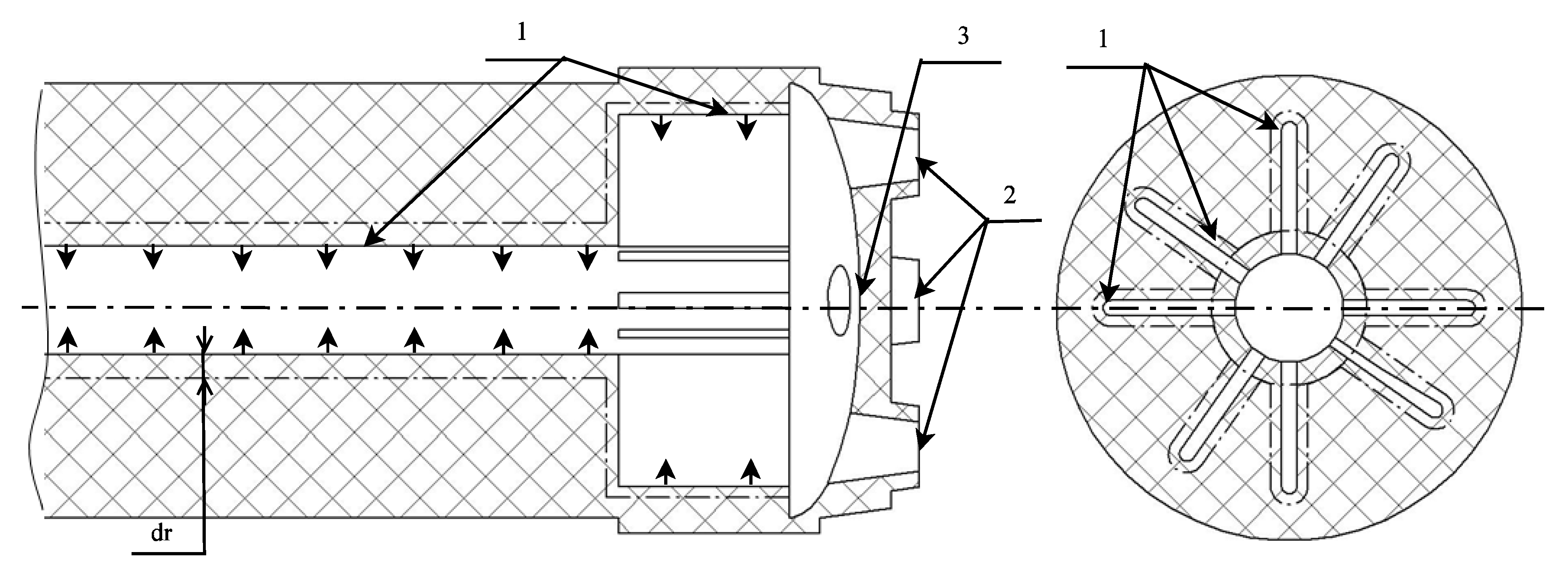
Figure 1. Calculation area: 1–the mass supply surface, 2–nozzle outlet, 3–nozzle bottom.
Applsci 11 04990 g001
Figure 2. Relative pressure distribution over the nozzle bottom and end surface.
Applsci 11 04990 g002
Figure 3. Transformation of peripheral structures in the vicinity of the nozzle cover at PP operation: black lines are current lines, color counter is a field of heat transfer coefficient (minimal is a blue color, maximal is a red color), where (a) for time 0.0001[s], (b) for time 0.0002[s],(c) for time 0.0003[s], (d) for time 0.0004–0.0005[s], (e) for time 0.0006[s] and (f) for time 0.0007–0.001[s].
Applsci 11 04990 g003
Figure 4. Rearrangement of the flow structure near the impermeable end of the PP channel: black lines are current lines, color counter is a field of heat transfer coefficient (minimal is a blue color, maximal is a red color), where (a) for time 0.0001[s], (b) for time 0.0002–0.0005[s],(c) for time 0.0006–0.001[s].
Applsci 11 04990 g004
Figure 5. Obtained intervals of quasi-stationary topological modes with an account of changes in thermal conditions at the point of stagnation: black lines are flow lines, color counter is a field of heat transfer coefficient (minimal is a blue color, maximal is a red color).
Applsci 11 04990 g005
Table 1. Boundary conditions.
BoundaryCondition
Mass supply surface InletT = 2500K, G = 15 m/s, d u d t = f ( p ) .
Nozzle outlet d p n = 0 .
Nozzle bottom and end surface (walls)U = V = W = 0, Twall (x, y, z, t)|wall = Tgas(x, y, z, t)|gas, λ w a l l ( T w a l l n ) S w a l l = λ g a s ( T g a s n ) S g a s
Publisher’s Note: MDPI stays neutral with regard to jurisdictional claims in published maps and institutional affiliations.