
An Experimental Validation of Numerical Model for Top-Hat Tubular Structure Subjected to Axial Crush


1
Mechanical Engineering Department, University of Anbar, Ramadi P.O. Box 5543, Iraq
2
Department of Mechanical and Industrial Engineering, Qatar University, Doha 2713, Qatar
*
Author to whom correspondence should be addressed.
Appl. Sci. 2021, 11(11), 4792; https://doi.org/10.3390/app11114792
Submission received: 29 March 2021
/
Revised: 18 May 2021
/
Accepted: 20 May 2021
/
Published: 23 May 2021
(This article belongs to the Special Issue Mechanical Behavior of Fiber Reinforced Composites)
Abstract
:Featured Application
The specific application of this work can be used for vehicle frontal longitudinal members for crash energy absorption during an accident.
Abstract
Vehicle crashworthiness is an important aspect to consider when designing a vehicle to ensure the safety of the occupants. Besides this, vehicles are also designed to reduce weight for better fuel economics. One possible approach to reducing weight without compromising vehicle safety is by looking at new designs and usage of composite materials, along with the usage of computational models to reduce time and cost. Hence, this paper displays the experimental results of a carbon fiber reinforced closed top-hat section subjected to both quasi-static and dynamic crushing loading. The results were used to validate the computational model developed in the study. The specimens were made of carbon composite prepregs MTM-44 sheets stacked at the alternative orientation of ±45° and 0°/90°, where 0° direction coincides with the axis of the member. The samples were prepared by using a mold and carbon prepregs under vacuum bagging followed by curing in an autoclave. Trigger initiation was applied to ensure the specimens demonstrated a stable crushing mode of failure during the test. Experimental investigations were carried out under the ambient conditions with different loading conditions, and different kinetic energy ranges (2, 3 and 6 kJ). Experimental data was used to validate the finite element analysis (FEA). The maximum errors obtained between experimental and FEA for mean load, mean energy absorption, and crushing displacement were 13%, 13% and 7%, respectively. The numerically obtained results were in strong agreement with the experimental data and showed that they were able to predict the failure of the specimens. The work also showed the novelty of using such structures for energy absorption applications.
1. Introduction
Crashworthiness is a research field that is never obsolete since occupant safety is a very important aspect to be considered when designing vehicles. Everyday new vehicle designs are developed with different applications and requirements. For example, the crashworthiness requirements for electrical vehicles is different from traditional vehicles [1] because additional safety features are required to protect the battery cells. In terms of designing for crashworthiness, a lot of work has been conducted looking into various material, shapes, sizes, and loading conditions [2,3,4,5,6,7,8,9,10,11,12,13,14,15,16]. Several composite sandwich designs such as inserts and foam-core hybrid composites were tested and it was found that these configurations have good energy absorption capabilities [2,6,15,16]. In another study, coconut-inspired designs were used to enhance crashworthiness performance [3]. Composite corrugated tubes were also found to have excellent crushing behavior which corresponded to good energy absorption capabilities [5,11,12]. Some researchers [7,8,10] studied metal corrugated tubes produced by traditional manufacturing techniques and by additive manufacturing. Similar to corrugated composite material tubes, metallic corrugated tubes are good for absorbing energy due to axial and oblique loadings. In other studies, different types of design configurations such as bi-tubular arrangements, and different cross-sectional geometries were explored [9,13]. These studies have shown that proper design, along with material selection, is vital for designing an effective tube for crashworthiness application. Besides usage of aluminum, steel and composite, Faris et al. [14] explored the usage of magnesium alloy for crashworthiness application. The study suggests that magnesium alloy has good potential because of its high specific energy absorption capabilities.
Composite materials have been shown to have better crashworthiness performance compared to their metal counterparts in terms of specific energy absorption [17,18,19,20,21]. One of the contributing factors for why composite materials display higher specific energy absorption is largely due to the failure mechanism of this material under compression load. Different types of failure modes exist concurrently such as buckling, fiber matrix debonding, interlaminar failure, matrix cracking, friction, and fiber breakage. Each of these contribute towards the energy absorption capabilities, giving them higher specific energy absorption than metallic structures [22,23,24]. Due to cost reasons, a lot of work has investigated the usage of glass fiber composites, also known as glass fiber reinforced plastics (GFRP), in the area of energy absorption due to compression. GFRP has been extensively used in many car parts instead of metal with a weight saving ranging from 40% to 60%, while maintaining or improving the performance compared to metallic components [25,26,27,28,29]. N.A. Warrior et al. showed that glass/epoxy composites absorbed greater energy than glass/vinyl ester and vinyl ester absorbed 33% more energy than polyester composites. Additionally, the study demonstrated that specific energy absorption of glass/epoxy composites is up to twice that of steel [30]. R. Muralikannan et al. studied glass fiber reinforced circular tubes subjected to axial compression in quasi-static and dynamic loading. The study observed that energy absorbed due to dynamic loading is less than in static loading and that both static and dynamic loading exhibit the same failure of modes. The study also concluded that the impact speed does not have a major influence in energy absorption for the same tube’s D/t ratio [31].
Besides GFRP, carbon fiber reinforced polymer/plastic (CFRP) has become an attractive material in the aerospace and automobile industries due to its light weight, high strength to weight and stiffness to weight ratios, high energy absorption, and easy manufacturing [13,14,15,16]. Stanislaw Ochelski and Pawel Gotowicki studied composite material reinforced cone shapes under axial compression. They found that the specific energy absorption of carbon fiber reinforced composites is 20% higher than glass fiber composites [32]. Ochelski and Gotowicki studied the energy absorption behavior of carbon/epoxy and glass/epoxy composites conical tubes subjected to axial compression. The results showed that increasing fiber angle could lead to an increase in the energy absorption of the tubes due to the fibers oriented in the circumference direction [32]. Many studies demonstrated that fiber orientation influences the absorbed energy by the structure. Hull has investigated the effect of fiber orientation. He found that the specific energy absorption increases as fiber angle increases. This behavior is valid until ±65° and from there on the specific energy starts to decrease [33]. Volume fraction, fiber orientation, and mechanical properties of the composite are most parameters that affect the higher energy absorption and hence the performance of the structure [34,35,36].
Based on the published works, it is safe to say that there is still room for practical design solutions that are lightweight, easy to fabricate and have vast structural applications. One of these is composite closed top-hat sections that have not received much attention from researchers. The aim and objective of this study will be to investigate the energy absorption capabilities of composite closed top-hat sections for axial crush loads. This will be used to validate a finite element model that will be used for future studies to optimize the design for crashworthiness application.
2. Materials and Experiment Setups
The material used in this study to form the composite top-hat and closure plate was carbon fiber prepregs and epoxy MTM44/CF5804A-40%RW-DC. MTM44 is a high performance, 180 °C (356 °F) curing, and toughened epoxy resin manufactured to produce primary and secondary aircraft structures. MTM44 is designed for autoclave molding or low-pressure vacuum bag Out-of-autoclave (OoA). The advantages of MTM44 include low density and a high level of damage. The fabric weight is 285 g/m2 and the prepreg’s weight is 475 g/m2. The volume fraction of the fiber is 60%. The stack sequences used to form the experimental parts (top-hat section) were [±45/0–90/90–0/±45].
To fabricate the top-hat section, a tool is required to serve as a mold (see Figure 1). In this study, the width and the height of the tool were 250 and 60 mm, respectively. The face side was 65 mm long. The tool was made from aluminium series 5754 with a thickness of 2.5 mm. The length of the tool was 800mm with nine ribs, placed 100 mm apart, welded beneath the tool to prevent any bending or movement during stacking material and manufacturing. Besides welding the ribs to the tool, two metal rods were placed along the length of the tool and attached to the ribs to ensure the stability of the tool during processing. The ribs were made from aluminium series AA5754 with a thickness of 2.5 mm. Aluminium was used to enhance heat transfer when curing and cooling down.
In the layup process, layers of the material were carefully stuck in the mold according to the orientation of each. After sticking each ply, a small roller was used with a smooth motion to remove any fold or wrinkling during the process (also to remove any air gaps). The best way to remove folds is to start moving the roller from one edge and working along the plies, with the focus on corners or any concave areas. A Polytetrafluoroethylene (PTFE) release film layer was placed between the tool and the composite to prevent sticking the part with the tool. The PTFE film provides excellent resistance to chemical splashes and is easy to clean (wipe down). It is also very capable of resisting contamination by aqueous and oily fluids. The prepregs were placed on the PTFE film and covered with the release film, then the breathing layer was be placed on top of the release film. The main use of the breathing layer is to absorb resin from the laminate and to ensure complete evacuation of air from the vacuum bag during the process. Bagging film covered the mold and was fixed by the tacky tape to the mold. The vacuum ports were attached over the bagging film. The extra thickness of breathing layers were placed underneath the vacuum port to ensure that the air was still drawn through the port even when a vacuum had compressed the breathing layer and to ensure no resin could be passed through the vacuum port. Figure 2 illustrates the vacuum bagging process used for this study. The composite part was then placed in an oven for curing. The curing temperature was set at 130 °C for two hours, then the temperature was increased to 180 °C for another two hours. This was followed by the part cooling down at a rate of 2–3 °C /min, with the vacuum port still attached to the vacuum during this process. The number of prepreg layers was 2 per layer, resulting in 16 plies for 8 layers.
After curing, the contact area for both top-hat and closure plate were roughened using an abrasive material. The purpose of this is to remove any oily area that affects the adhesive material. SikaPower-490 C was used as an adhesive material. SikaPower-490 C is a two-component adhesive which was designed for steel, aluminium and CFRP bonding. The adhesive is suitable for structural and crash resistant application. The adhesive was applied to the roughened area. After applying the adhesive material on both parts, the closure was attached to the top-hat part and clamps were used to ensure uniform thickness in all contact areas and to get rid of any bubbles from the adhesive. The assembled part was placed at room temperature for four hours after joining and then placed in an oven for 30 min at 85 °C. Composite part will be trimmed to get a uniform edge and desired dimensions by using a band saw (Addison) while the initiator was prepared by using MACC special 400 CSO saw. The sample was later cut into two specimens with length 300 mm.This process was repeated top achieve the desired number of samples for this study.
To support the development of the finite element model, some material properties were required. To facilitate this, square composite flat plates consisting of 6 plies with a dimension of 550 × 550 mm (average thickness of 2 mm) were manufactured using the vacuum bagging technique as described above. The material used in this study was carbon fiber prepregs MTM44/CF5804A. After curing, the plate was cut to a rectangular cross-section to produce an orientation of both [0/90°] and [±45°] according to the ASTM D30309/D3039M test method [37]. The samples were placed into two grips of a mechanical Instron 5800R 100 kN testing machine. The specimens were loaded axially towards the moving grip. Two transducers were placed at the center of the specimen to record both longitudinal and transverse strains. Force-displacement and stress–strain curves were specified and recorded automatically in the equipment software so that other mechanical properties such as modulus of elasticity, Poisson’s ratio and tensile strength could be calculated (Figure 3). The ultimate strength of each sample of the material was determined from the maximum force carried before failure. Mechanical properties obtained from coupon testing and used in the numerical simulation are listed in Table 1. Figure 4 shows the coupon samples with two different orientations subjected to the quasi-static load.
The axial static crushing test was conducted by using Zwick ±250 kN Fatigue Instron equipment while the axial dynamic crushing tests were conducted on the Instron Spring Assisted, Instrumented Drop Tower as shown in Figure 5. The instrument is designed to provide 10 kJ of impact energy delivered from two springs with the impactor then moving in free fall (depending on fixture & specimen heights). The impact mass is 67.4 kg and additional weights can be bolted onto the impactor to increase its mass up to a total of 156 kg (without fixtures). Hence, the maximum impact energy of around 11 kJ can be achieved, corresponding to a maximum velocity of 12 m/s. The benefits of using this instrument are that it enables the ability to test small and large structures under laboratory conditions, provides high impact velocities, has low operational costs, a high-speed camera can be conducted and has automated pick-up of impact mass.
The test specimens fabricated were placed at the center of the equipment between the moving plate and the fixed plate, one of the structure’s ends was chamfered (initiated) and modelled and was placed upwards at the top of the profile towards the moving plate to ensure the progressive and stable collapse of the profile during the test. The specimens for plies with [±45/0–90/90–0/±45] orientation were crushed under three different kinetic energies 2.1, 3.2 and 6.6 kJ with the impact mass of 78 kg at room temperature. For simplification, these energy levels are abbreviated as 2 kJ, 3 kJ and 6 kJ through the paper. Dynamic crushing tests were carried out to evaluate energy absorption characteristics. A high-speed camera (FASTCAM SA-X2) with rate of 5000 frames/s was placed to capture the crushing of the specimen and record the deformation during the test.
3. Finite Element Model
The well-known non-linear finite element code ABAQUS was chosen in this study to predict the behavior of carbon fiber reinforced composite. The composite layup property editor provides a table that enables users to define each ply in the laminate separately including ply name, material, thickness, and orientation (for plies with [0/90°] orientation). The stratification of composite material is defined by using the composite layup feature of ABAQUS. The composite layup tool only allows surface discretized with shell elements to model stacking sequences instead of as many surfaces as the number of layers that constitutes the real stack. In the composite layup modulus, for each set of elements corresponding to specific zones of the specimen, it is possible to define: (1) the number of plies; (2) the material that constitutes the ply; (3) the orientation of the fibers; (4) individual ply thicknesses.
The profile geometry was modelled by using linear shell element S4R node doubly curved, reduced integration, hourglass control, and finite membrane strains. Both fixed and moving plates were modelled as linear discrete rigid element R3D4 bilinear quadrilateral. The element mesh size was 5 mm after conducting sensitivity analysis (maximize accuracy without increased computational time). The composite specimen was placed between two plates which had been modelled as rigid shell plates. The bottom plate was fixed in all directions and the motion in any direction was a constraint in all degree of freedom (U1=U2=U3=UR1=UR2=UR3=0) while the crushing speed assigned to the top plate (striker) with a mass of 78 kg had been uniformly applied. The top plate was modelled to move axially towards the specimen and restricted from moving in other directions. A trigger (chamfer) was applied at the top of the profile to ensure the stable progress collapse during the test (similar to experimental tests). Figure 6 depicts the FE model used.
The contact interaction for the entire model was set as general contact and was used to avoid any interpenetration of the profile wall. The contact of the whole model was defined using a finite sliding penalty-based contact algorithm with contact pairs and “hard” contact. The friction coefficient value of all contact surfaces was set at 0.2 [38,39]. An adhesive layer was used to attach the closure plate to the top-hat profile. Sixteen plies were used to simulate the profile [±45/0–90/90–0/±45] orientation as well as the closure plate with three integration points with overall thickness of 2.6 mm for the profile and the closure plate. Each shell represented one ply. Mechanical properties of the composite material used in the simulation procedure are listed in Table 1. To model the progressive failure of the composite structure, Hashin’s theory was utilized [40]. The Hashin criterion takes account of four independent modes of damage: fiber tension, fiber compression, matrix tension and matrix compression. When one of the damage initiation criterion is met, the elements are programmed to be deleted at the ply where the damage was detected (Hashin failure criteria). The element deletion is a very effective strategy in modelling progressive composite failure [40]. This failure criterion was adopted for its ease of implementation in the finite element software.
4. Results and Discussion
The specimens were subjected to three different kinetic energy levels (2 kJ, 3 kJ and 6 kJ). Total impact mass used was 78 kg to keep the inertia effect constant during the study. The force-displacement and energy-displacement curves for the different kinetic energy levels are shown in Figure 7. Once the upper platen contacted the top of the specimen (initiator), the specimen started to compress, internal ply delamination started, and the specimen suffered from splaying away from the center. The load increased until there was 12 mm of the crushing displacement. Beyond 12 mm, there was no more increase in the load, the load flattened out as the specimen was crushed and started to decrease gradually. The initial increase in the load appeared to be linear followed by a flattening of the load as the specimen was crushed; this can be attributed to the initiator. The impact speed did not have a significant effect on the force or even the initial force. From the energy-displacement curves, the energy increased as crushing speed increased and the responses for different speeds were consistent. The energy increased until the maximum level then started to rebound due to the non-deformed closure plate which absorbed the energy and then released it. This finding confirmed what has been reported by Farley [41], as well as Berry and Hull [42], who studied many tubes subjected to different crushing speeds. They mentioned that the energy absorption increased linearly as crushing speed increased. Mamalis [24,40] also studied CFRP square tubes under dynamic crushing loads. He found that energy absorption increased with the crushing speed.
The predicted force-displacement results from the finite element analysis are shown in Figure 8, Figure 9 and Figure 10. For each speed value, three experiment tests were conducted for repeatability purpose. The initial results were almost the same as the experimental values until 14 mm (2 and 3 kJ) and 18 mm (6 kJ) of the crushing stroke when the load increased rapidly. After exceeding these displacements, the load was slightly lower than experimental values and it can be clearly observed in Figure 10. After that, the load tended to behave almost the same as experimental behavior. The peak loads in predicted results increased slightly with increasing kinetic energy (speed). Load-displacement curves produced an oscillating result, so the filter has been applied to compare with the experimental curves. An example of progressive crushing from the finite element model is depicted in Figure 11. There is good correlation between the finite element model and the experimental tests when the energy absorption is compared with the displacement as shown in Figure 8, Figure 9, Figure 10. Table 2 shows the comparison between experimental and numerical simulations of key crashworthiness parameters. The maximum difference was found to be at 13% between the experimental and FEA results. This is within the acceptable range for computational / finite element analysis [43,44]. To add to this, the comparison was made between the average values of the experimental results and the FEA results. Besides this, for complex and non-linear problems such as the crushing of composite structures, errors below 20% are acceptable because the composite material failure models used in modelling are not exact models. Active research is still ongoing in this aspect [45,46].
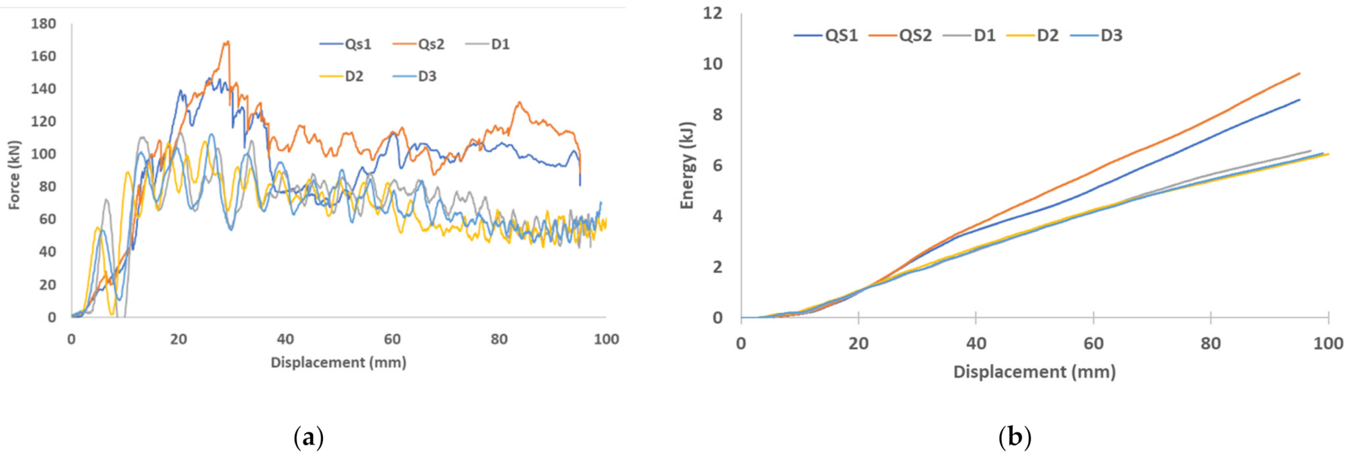
The differences in energy absorption and peak load of the fiber reinforced closed top-hat section subjected to both dynamic and quasi-static axial crushing tests are shown in Figure 12. The average peak loads of the dynamic test for 2, 3 and 6 kJ kinetic energy were 107, 108 and 112 kN, respectively, with a reduction from 35% to 45% compared with the quasi-static test. In addition, the average energy absorption of the dynamic test for 2, 3 and 6 kJ kinetic energy were 2050, 3180 and 6500 J, respectively, with a reduction from 28% to 77% compared with the quasi-static test. The average energy absorption of dynamic impact was 6300 J with a reduction of 30% compared with static loading for the same deformation length. The reduction in energy absorption is attributed to the changing of the deformation mode due to crushing speed and to the reduction in friction for the dynamic cases compared to the quasi-static. A video of the dynamic crushing is available in the Supplementary Materials.
5. Conclusions
This study showed an experimental investigation into and finite element predictions of axial crushing behavior and crashworthiness characteristics of carbon fiber reinforced hat-shaped tubes. Different velocities were conducted. The impact speed and force-displacement curves were explored for closed top-hat profiles fabricated by the vacuum bagging process. Explicit FE code ABAQUS were used to develop the crash energy absorption of composite materials. Experimental failure modes and load-displacement curves of the top-hat section were validated. Numerical and experimental results were compared to determine the predictive capability of the finite element modelling of the top-hat composite sections. The maximum difference was found to be 13% between the experimental and FEA results. This is within the acceptable range for finite element analysis [44,45]. To add to this, the comparison was made between the average values of the experimental results against the FEA result. Besides this, for complex and non-linear problems such as the crushing of composite structures, errors below 20% are acceptable because the composite material failure models used in modelling are not an exact model. Active research is still ongoing in this aspect [45,46]. Below are some of the conclusions that can be derived from this study:
- Increases in impact speed led to increases in energy absorption and the energy absorption increases linearly with the impact speed
- The predicted force-displacement and energy-displacement results for different speeds have shown good agreement with the experimental results. Therefore, it can be concluded that the numerical model was able to predict the failure and behavior of the closed top-hat.
- The average peak loads of the dynamic test 2 kJ, 3 kJ and 6 kJ were 107, 108 and 112 kN, respectively, with a reduction of 35% to 45% compared with the quasi-static test. In addition, the average energy absorption of the dynamic test with 2, 3 and 6 kJ were 2050, 3180 and 6500 J, respectively, with a reduction from 28% to 77% compared with the quasi-static test.
Now that the finite element model has been validated, the next step is to use this model in a full vehicle finite element model to evaluate the crash performance followed by optimizing the top-hat structure to enhance energy absorption.
Supplementary Materials
The following are available online at https://www.mdpi.com/article/10.3390/app11114792/s1, Video S1: Dynamic crushing of hat structures.
Author Contributions
S.F.A. conceptualized the aims and objectives of the paper followed with the experimental work and data analysis. F.T. worked on the writing—original draft preparation, writing—review and editing the manuscript. Both authors have read and agreed to the published version of the manuscript.
Funding
This research received no external funding.
Institutional Review Board Statement
Not applicable.
Informed Consent Statement
Not applicable.
Data Availability Statement
Not applicable.
Acknowledgments
This investigation was supported by the Council for at Risk Academy (CARA). The authors would like to acknowledge the university of Warwick and Warwick manufacturing group (WMG) and staff for providing full support, equipment and all facilities to complete this research. Also, great appreciation for the Sika Power company for providing an adhesive which is necessary for this investigation. The authors would also like to acknowledge Qatar National Research Fund for providing financial assistance to publish this paper as open access.
Conflicts of Interest
The authors declare no conflict of interest. The funders had no role in the design of the study; in the collection, analyses, or interpretation of data; in the writing of the manuscript, or in the decision to publish the results.
References
- Mudassir, M.; Tarlochan, F.; Mansour, M.A. Nature-Inspired Cellular Structure Design for Electric Vehicle Battery Compartment: Application to Crashworthiness. Appl. Sci. 2020, 10, 4532. [Google Scholar] [CrossRef]
- Tarlochan, F.; Hamouda, A.M.S.; Mahdi, E.; Sahari, B.B. Composite sandwich structures for crashworthiness applications. Proc. Inst. Mech. Eng. Part L J. Mater. Des. Appl. 2007, 221, 121–130. [Google Scholar] [CrossRef]
- Shen, J.; Flores, M.; Sharits, A. Impact Performance of a Plate Structure with Coconut-Inspired Microchannels. Appl. Sci. 2020, 10, 355. [Google Scholar] [CrossRef] [Green Version]
- Borrelli, A.; D’Errico, G.; Borrelli, C.; Citarella, R. Assessment of Crash Performance of an Automotive Component Made through Additive Manufacturing. Appl. Sci. 2020, 10, 9106. [Google Scholar] [CrossRef]
- Elgalai, A.M.; Mahdi, E.; Hamouda, A.M.S.; Sahari, B.S. Crushing response of composite corrugated tubes to quasi-static axial loading. Compos. Struct. 2004, 66, 665–671. [Google Scholar] [CrossRef]
- Eyvazian, A.; Taghizadeh, S.A.; Hamouda, A.M.; Tarlochan, F.; Moeinifard, M. Buckling and crushing behavior of foam-core hybrid composite sandwich columns under quasi-static edgewise compression. J. Sandw. Struct. Mater. 2020. [Google Scholar] [CrossRef]
- Alkhatib, S.E.; Matar, M.S.; Tarlochan, F.; Laban, O.; Mohamed, A.S.; Alqwasmi, N. Deformation modes and crashworthiness energy absorption of sinusoidally corrugated tubes manufactured by direct metal laser sintering. Eng. Struct. 2019, 201, 109838. [Google Scholar] [CrossRef]
- Mohamed, A.S.; Laban, O.; Tarlochan, F.; Al Khatib, S.E.; Matar, M.S.; Mahdi, E. Experimental analysis of additively manufactured thin-walled heat-treated circular tubes with slits using AlSi10Mg alloy by quasi-static axial crushing test. Thin-Walled Struct. 2019, 138, 404–414. [Google Scholar] [CrossRef]
- Dastjerdi, A.A.; Shahsavari, H.; Eyvazian, A.; Tarlochan, F. Crushing analysis and multi-objective optimization of different length bi-thin walled cylindrical structures under axial impact loading. Eng. Optim. 2019, 51, 1884–1901. [Google Scholar] [CrossRef]
- Eyvazian, A.; Mozafari, H.; Tarlochan, F.; Hamouda, A.M.S. Numerical and experimental investigation on corrugation geometry for metallic tubes under lateral loading. Mater. Sci. Forum 2018, 916, 226–231. [Google Scholar] [CrossRef]
- Alkhatib, S.E.; Tarlochan, F.; Hashem, A.; Sassi, S. Collapse behavior of thin-walled corrugated tapered tubes under oblique impact. Thin-Walled Struct. 2018, 122, 510–528. [Google Scholar] [CrossRef]
- Sami, A.E.; Alkhatib, E.; Tarlochan, F. Collapse behavior of thin-walled corrugated tapered tubes. Eng. Struct. 2017, 150, 674–692. [Google Scholar]
- Tarlochan, F.; Samer, F.; Hamouda, A.M.S.; Ramesh, S.; Khalid, K. Design of thin wall structures for energy absorption applications: Enhancement of crashworthiness due to axial and oblique impact forces. Thin-Walled Struct. 2013, 71, 7–17. [Google Scholar] [CrossRef]
- Tarlochan, F.; Samer, F. Design of thin wall structures for energy absorption applications: Design for crash injuries mitigation using magnesium alloy. Int. J. Res. Eng. Technol. 2013, 2, 24–36. [Google Scholar]
- Tarlochan, F.; Ramesh, S.; Harpreet, S. Advanced composite sandwich structure design for energy absorption applications: Blast protection and crashworthiness. Compos. Part B Eng. 2012, 43, 2198–2208. [Google Scholar] [CrossRef]
- Tarlochan, F.; Ramesh, S. Composite sandwich structures with nested inserts for energy absorption application. Compos. Struct. 2012, 94, 904–916. [Google Scholar] [CrossRef]
- Xu, J.; Ma, Y.; Zhang, Q.J.; Sugahara, T.; Yang, Y.Q.; Hamada, H. Crashworthiness of carbon fibre hybrid composite tubes molded by filament winding. Compos. Struct. 2016, 139, 130–140. [Google Scholar] [CrossRef]
- Wang, Y.F.; Feng, J.S.; Wu, J.H.; Hu, D.Y. Effects of fibre orientation and wall thickness on energy absorption characteristics of carbon-reinforced composite tubes under axial quasi-static and impact crushing condition. Compos Struct 2016, 13, 356–368. [Google Scholar] [CrossRef]
- Hu, D.Y.; Luo, M.; Yang, J.L. Experimental study on crushing characteristics of brittle fibre/epoxy hybrid composite tubes. Int. J. Crashworthiness 2010, 15, 401–412. [Google Scholar] [CrossRef]
- Song, H.W.; Wan, Z.M.; Xie, Z.M.; Du, X.W. Axial impact behaviour and energy absorption efficiency of composite wrapped metal tubes. Int. J. Impact Eng. 2000, 24, 385–401. [Google Scholar] [CrossRef]
- Yan, L.; Chouw, N. Crashworthiness characteristics of flax fibre reinforced epoxy tubes for energy absorption application. Mater. Des. 2013, 51, 629–640. [Google Scholar] [CrossRef]
- Mamalis, A.G.; Robinson, M.; Manolakos, D.E.; Demosthenous, G.A.; Ioannidis, M.B.; Carruthers, J. Crashworthy capability of composite material structures. Compos. Struct. 1997, 37, 109–134. [Google Scholar] [CrossRef]
- Mamalis, A.G.; Manolakos, D.E.; Ioannidis, M.B.; Papapostolou, D.P. On the experimental investigation of crash energy absorption in laminate splaying collapse mode of FRP tubular components. Compos. Struct. 2005, 70, 413–429. [Google Scholar] [CrossRef]
- Mamalis, A.G.; Manolakos, D.E.; Ioannidis, M.B.; Papapostolou, D.P. On the response of thin-walled CFRP composite tubular components subjected to static and dynamic axial compressive loading: Experimental. Compos. Struct. 2005, 69, 407–420. [Google Scholar] [CrossRef]
- Ning, H.; Pillay, S.; Vaidya, U.K. Design and development of thermoplastic composite roof door for mass transit bus. Mater. Des. 2009, 30, 983–991. [Google Scholar] [CrossRef]
- Janowski, G.M.; Vaidya, U.K.; Husman, G. Thermoplastic sandwich structure design and manufacturing for the body panel of mass transit vehicle. Compos. Struct. 2007, 80, 82–91. [Google Scholar]
- Ning, H.; Vaidya, U.K.; Janowski, G.M.; Husman, G. Design, manufacture and analysis of a thermoplastic composite frame structure for mass transit. Compos. Struct. 2007, 80, 105–116. [Google Scholar] [CrossRef]
- Thattaiparthasarthy, K.B.; Pillay, S.; Ning, H.; Vaidya, U.K. Process simulation, design and manufacturing of a long fibre thermoplastic composite for mass transit application. Compos. Part A Appl. Sci. Manuf. 2008, 39, 1512–1521. [Google Scholar] [CrossRef]
- Bartus, S.D.; Vaidya, U.K.; Ulven, C.A. Design and development of a long fibre thermoplastic bus seat. J. Compos. Mater. 2006, 19, 131–154. [Google Scholar] [CrossRef]
- Warrior, N.A.; Turner, T.A.; Robitaille, F.; Rudd, C.D. Effect of resin properties and processing parameters on crash energy absorbing composite structures made by RTM. Compos. Part A 2003, 34, 543–550. [Google Scholar] [CrossRef]
- Muralikannan, R.; Velmurugan, R.; Eswaraprasad, G.L. Energy absorption characteristics of circular composites tubes in quasi static and impact loading. In Proceedings of the IMPLAST 2010 Conference, Providence, RI, USA, 12–14 October 2010. [Google Scholar]
- Ochelski, S.; Gotowicki, P. Experimental assessment of energy absorption capability of carbon-epoxy and glass-epoxy composites. Compos. Struct. 2009, 87, 215–224. [Google Scholar] [CrossRef]
- Hull, D. A unified approach to progressive crushing of fibre-reinforced composite tubes. Compos. Sci. Technol. 1991, 40, 337–421. [Google Scholar] [CrossRef]
- Kostopoulos, V.; Markopoulos, Y.P.; Vlachos, D.E.; Galiotis, C.; Melanitis, N.E. A Heavy-Duty Composite Bridge Made of Glass Polyester Pultruded Box Beams. In Proceedings of the RTO Applied Vehicle Technology Panel (AVT) Specialists’ Meeting on Low Cost Composite Structures, Loen, Norway, 7–11 May 2001. [Google Scholar]
- Bardi, F.C.; Yun, H.D.; Kyriakides, S. On the Axisymmetric Progressive Crushing of Circular Tubes under Axial Compression. Int. J. Solids Struct. 2003, 40, 3137–3155. [Google Scholar] [CrossRef]
- Lou, H.; Yan, Y.; Meng, X.; Jin, C. Progressive Failure Analysis and Energy-Absorbing Experiment of Composite Tubes under Axial Dynamic Impact. Compos. Part B Eng. 2016, 87, 1–11. [Google Scholar] [CrossRef]
- ASTM D30309/D3039M-14: Standard test method for tensile properties of polymer matrix composite.
- Ahmad, Z.; Thambiratnam, D.P.; Tan, A.C.C. Dynamic energy absorption characteristics of foam-filled conical tubes under oblique impact loading. Int. J. Impact Eng. 2010, 37, 475–488. [Google Scholar] [CrossRef]
- Witteman, W.J. Improved Vehicle Crashworthiness Design by Control of the Energy Absorption for Different Collisions Situation. Ph.D. Thesis, Eindhoven University of Technology, Eindhoven, The Netherlands, 1999. [Google Scholar]
- Mamalis, A.G.; Manolakos, D.E.; Ioannidis, M.B.; Papapostolou, D.P. The static and dynamic axial collapse of CFRP square tubes: Finite element modelling. Compos. Struct. 2006, 74, 213–225. [Google Scholar] [CrossRef]
- Farley, G.L. Effect of fiber and matrix maximum strain on the energy absorption of composite materials. J. Compos. Mater. 1986, 20, 322–334. [Google Scholar] [CrossRef]
- Berry, J.; Hull, D. Effect of speed on progressive crushing of epoxy glass cloth tubes. In Institute of Physics Conference Series; Plenum Publishing Corp: New York, NY, USA, 1984; p. 463.e70. [Google Scholar]
- Zingoni, A. Insights and Innovations in Structural Engineering Mechanics and Computation. In Proceedings of the Sixth International Conference on Structural Engineering, Mechanics and Computation, Cape Town, South Africa, 5–7 September 2016. [Google Scholar]
- Gupta, R.B.; Singh, S.K. Detection of Crack and Unbalancing in a Rotor System Using Artificial Neural Network. In Advances in Engineering Design; Prasad, A., Shakti, S., Gupta, R.K., Eds.; Sel. Proc. Flame; Springer: Singapore, 2018. [Google Scholar]
- Liu, P.F.; Zheng, J.Y. Recent developments on damage modeling and finite element analysis for composite laminates: A review. Mater. Des. 2010, 31, 3825–3834. [Google Scholar] [CrossRef]
- Guo, Q.; Yao, W.; Li, W.; Gupta, N. Constitutive models for the structural analysis of composite materials for the finite element analysis: A review of recent practices. Compos. Struct. 2021, 260, 113267. [Google Scholar] [CrossRef]
Figure 1.
(a) Overview of fabrication tool and specimen (b) tool design.

Figure 2.
(a) Detailed description of the vacuum bagging process (image source: “Vacuum bagging” by CORE-Materials is licensed with CC BY-NC-SA 2.0), (b) execution of bagging process in this study.
Figure 2.
(a) Detailed description of the vacuum bagging process (image source: “Vacuum bagging” by CORE-Materials is licensed with CC BY-NC-SA 2.0), (b) execution of bagging process in this study.
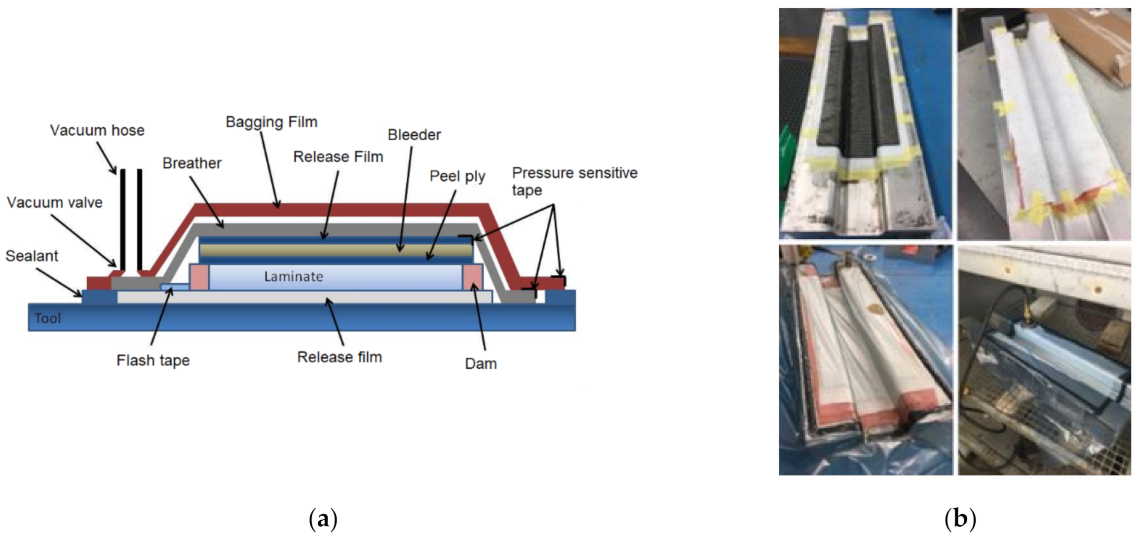
Figure 3.
(a) stress strain diagram for plies with [0/90°] orientation, where 5 samples were used for repeatability purpose, (b) stress–strain diagram for plies with [±45°] orientation, where 4 samples were used for repeatability purpose.
Figure 3.
(a) stress strain diagram for plies with [0/90°] orientation, where 5 samples were used for repeatability purpose, (b) stress–strain diagram for plies with [±45°] orientation, where 4 samples were used for repeatability purpose.
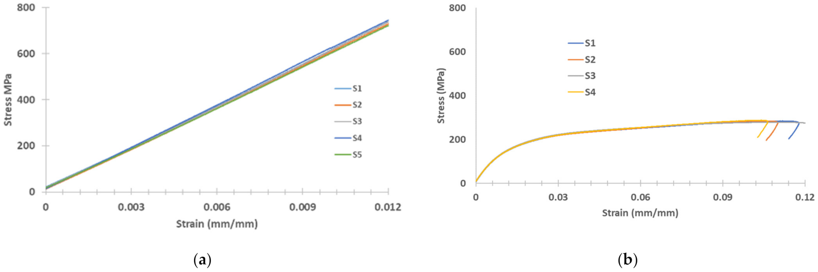
Figure 4.
Composite samples under quasi-static loading, (a) 0/90 and (b) ±45 orientation.
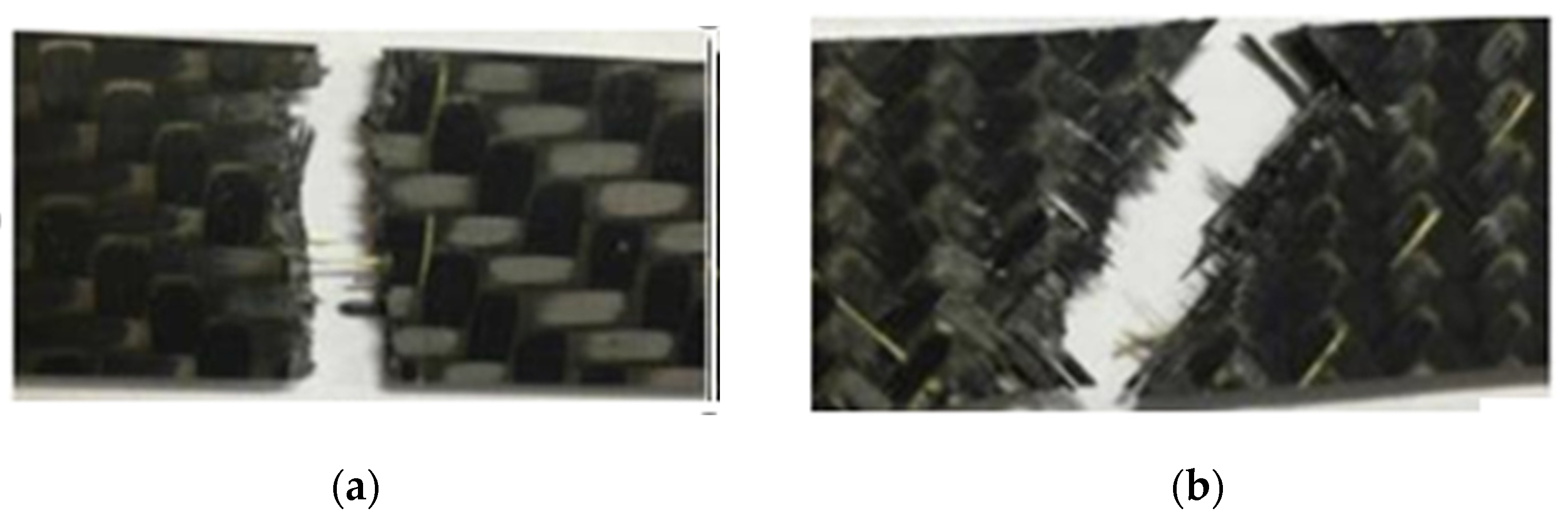
Figure 5.
Zwick ±250 kN Fatigue (left) and Instron Drop Tower (right).
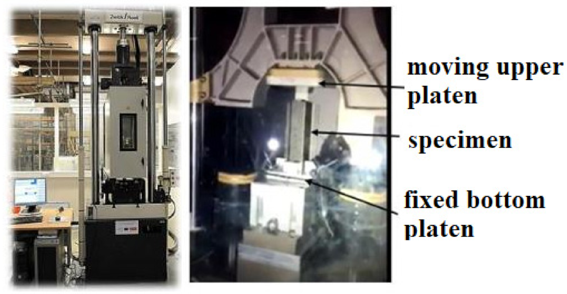
Figure 6.
Top-hat geometry, boundary conditions and layup.

Figure 7.
Example of dynamic force-displacement curves for different impact energy levels.
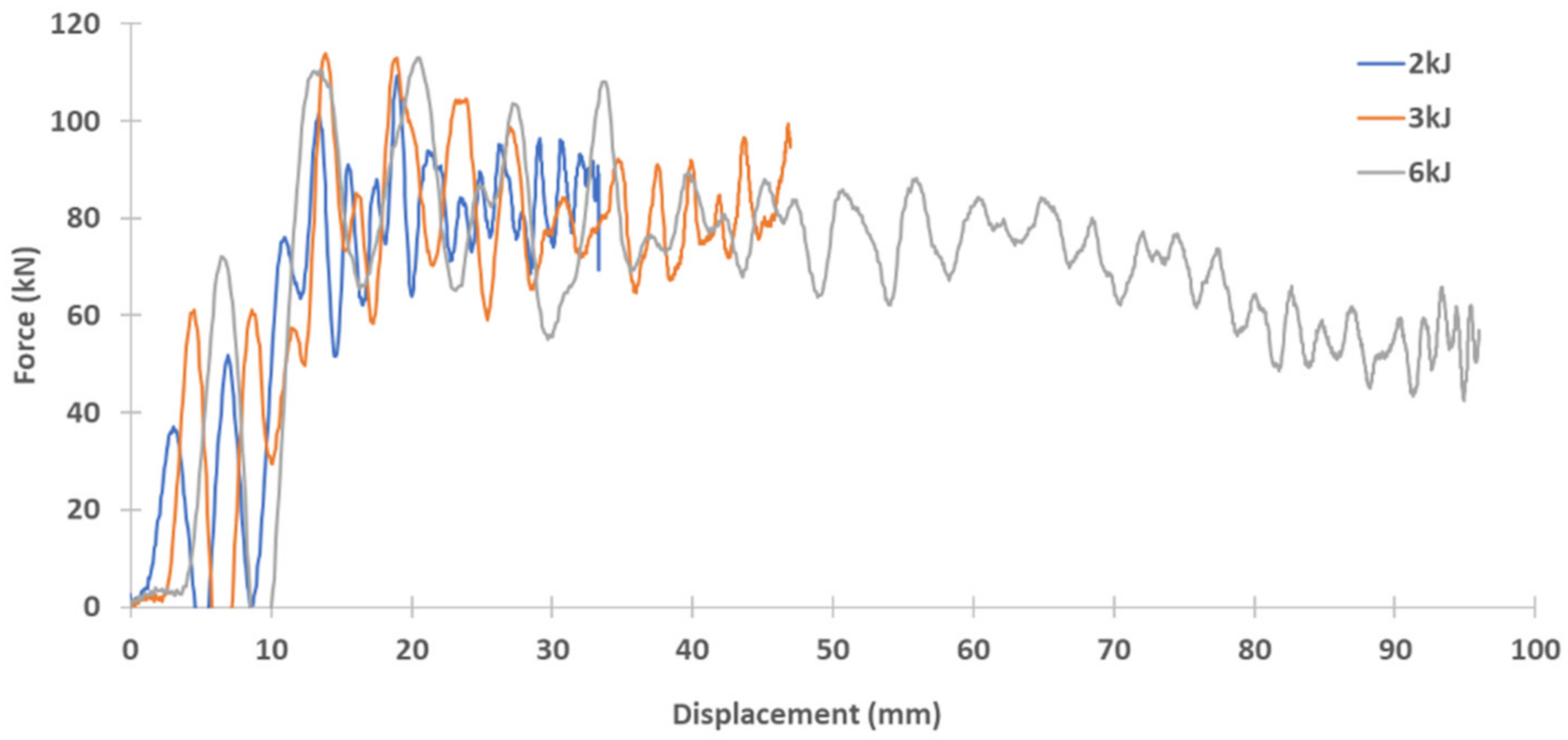
Figure 8.
Hat-shaped crush at kinetic energy of 2 kJ: (a) Dynamic experimental and F.E load vs. displacement curves, (b) Dynamic experimental and F.E energy vs. displacement curves.
Figure 8.
Hat-shaped crush at kinetic energy of 2 kJ: (a) Dynamic experimental and F.E load vs. displacement curves, (b) Dynamic experimental and F.E energy vs. displacement curves.

Figure 9.
Hat-shaped crush at kinetic energy of 3 kJ: (a) Dynamic experimental and F.E load vs. displacement curves, (b) Dynamic experimental and F.E energy vs. displacement curves.
Figure 9.
Hat-shaped crush at kinetic energy of 3 kJ: (a) Dynamic experimental and F.E load vs. displacement curves, (b) Dynamic experimental and F.E energy vs. displacement curves.
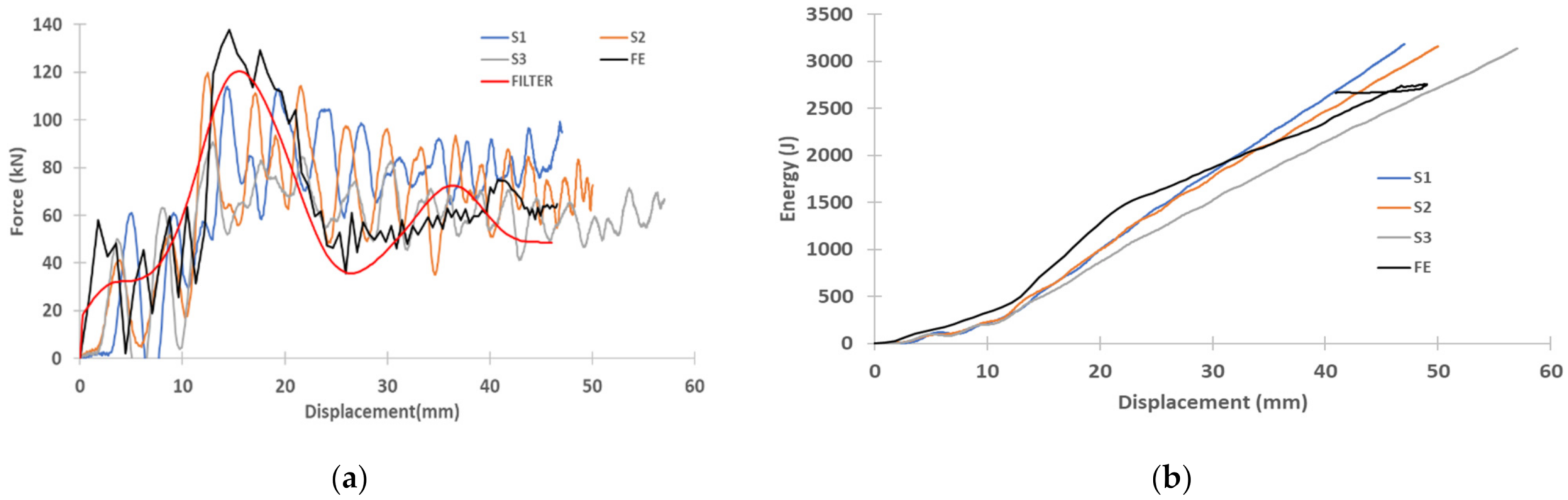
Figure 10.
Hat-shaped crush at kinetic energy of 6 kJ: (a) Dynamic experimental and F.E load vs. displacement curves, (b) Dynamic experimental and F.E energy vs. displacement curves.
Figure 10.
Hat-shaped crush at kinetic energy of 6 kJ: (a) Dynamic experimental and F.E load vs. displacement curves, (b) Dynamic experimental and F.E energy vs. displacement curves.
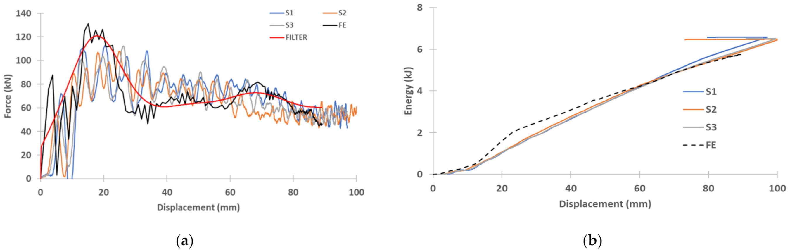
Figure 11.
Example of dynamic crushing of structure for 2 kJ test (numerical simulation). This figure shows the progressive crushing of the composite structure.
Figure 11.
Example of dynamic crushing of structure for 2 kJ test (numerical simulation). This figure shows the progressive crushing of the composite structure.

Figure 12.
(a) Force-displacement curves of dynamic and quasi-static axial crush (b) Energy-displacement curve of dynamic and quasi-static axial crush.
Figure 12.
(a) Force-displacement curves of dynamic and quasi-static axial crush (b) Energy-displacement curve of dynamic and quasi-static axial crush.

Table 1.
Mechanical properties of MTM44-1/CF5804A obtained from tensile test.
| Material Property | Units | Value |
|---|---|---|
| Young’s modulus, tension in direction | (GPa) | 70 |
| Young’s modulus, compression in direction | (GPa) | 70 |
| Shear modulus in plane 1–2/ | (GPa) | 4 |
| Poisson’s ratio in plane 1–2 | 0.05 | |
| Tensile strength in direction 1/(MPa) XT | Xt (MPa) | 760 |
| Compressive strength in direction 1 | Xc (MPa) | 610 |
| Shear strength in plane 1–2 | (MPa) | 100 |
Table 2.
Predicted and experimental results for composite material reinforced closed top-hat.
| Approximate Impact Energy | Parameter | Average Experimental | Numerical | Error % |
|---|---|---|---|---|
| ~2.1 kJ (sample ID: 2 kJ) | Mean load (kN) | 66.9 | 58.2 | 13 |
| Energy (J) | 2047 | 1850 | 10 | |
| Crushing length (mm) | 34 | 33.8 | 1 | |
| ~3.2 kJ (sample ID: 3 kJ) | Mean load (kN) | 66.6 | 62.3 | 6 |
| Energy (J) | 3179 | 2755 | 13 | |
| Crushing length (mm) | 50 | 48.8 | 2 | |
| ~6.6 kJ (sample ID: 6 kJ) | Mean load (kN) | 63 | 65.5 | 4 |
| Energy (J) | 6580 | 5756 | 13 | |
| Crushing length (mm) | 97 | 90 | 7 |
Publisher’s Note: MDPI stays neutral with regard to jurisdictional claims in published maps and institutional affiliations. |
© 2021 by the authors. Licensee MDPI, Basel, Switzerland. This article is an open access article distributed under the terms and conditions of the Creative Commons Attribution (CC BY) license (https://creativecommons.org/licenses/by/4.0/).
Share and Cite
MDPI and ACS Style
Abdulqadir, S.F.; Tarlochan, F. An Experimental Validation of Numerical Model for Top-Hat Tubular Structure Subjected to Axial Crush. Appl. Sci. 2021, 11, 4792. https://doi.org/10.3390/app11114792
AMA Style
Abdulqadir SF, Tarlochan F. An Experimental Validation of Numerical Model for Top-Hat Tubular Structure Subjected to Axial Crush. Applied Sciences. 2021; 11(11):4792. https://doi.org/10.3390/app11114792
Chicago/Turabian StyleAbdulqadir, Samer Fakhri, and Faris Tarlochan. 2021. "An Experimental Validation of Numerical Model for Top-Hat Tubular Structure Subjected to Axial Crush" Applied Sciences 11, no. 11: 4792. https://doi.org/10.3390/app11114792
Note that from the first issue of 2016, this journal uses article numbers instead of page numbers. See further details here.