Angular Dependence of Photonic Crystal Coupled to Photovoltaic Solar Cell


Department of Energy Engineering, University of Seville, Avda Camino de los descubrimientos, s/n, 41092 Seville, Spain
*
Author to whom correspondence should be addressed.
Appl. Sci. 2020, 10(5), 1574; https://doi.org/10.3390/app10051574
Submission received: 3 February 2020
/
Revised: 20 February 2020
/
Accepted: 21 February 2020
/
Published: 25 February 2020
(This article belongs to the Special Issue Advanced Solar–Wind–Hydro Hybrid Energy System)
Abstract
:Photonic crystals have the advantage of minimizing thermal losses from solar cells, reflecting the solar radiation that is not absorbed by the photovoltaic device. To optimize this optical response, photonic crystals are designed considering the relative position of the Bragg peak and the bandgap of the solar cell, under normal incident irradiation conditions. The aim of this research article was to determine experimentally the optical limits of a solar cell coupled to a photonic crystal acting as beam splitter. For that purpose, the photovoltaic system was characterized under indoor and outdoor conditions; angular dependence of the irradiation source was determined in each case, and both results were compared with good agreement. Moreover, other parameters such as irradiation spectrum and polarization of the light were investigated. The main conclusion is that photovoltaic performance is highly affected by the Bragg peak shifting and the profile is distorted, due to the angular dependence with the sun. These experimental limits must be considered at the early design stage to avoid performance losses.

1. Introduction
One-dimensional photonic crystal (1DPC) is a well-known concept with broad fields of application since their discovery in 1987 [1,2]. Their initial development was motivated to improve laser and optical fiber technologies [3,4,5], but today they have been extended to other commercial devices, like optical filters [6,7], high Q-photonic cavities [8,9], photocatalysis [10,11], high-temperature sensitive sensors [12], magnetoplasmonics [13], metamaterials [14], light tailoring [15], or even energy functionalization. [16].
Photonic crystals are also present in nature: these structured materials are present, for example, in ants to reflect light, and therefore, to reduce their temperature; butterflies use these periodic structures on their wings to scatter the light and generate their distinctive iridescent color [16]. Furthermore, they are used by chameleons for rapid modifications of their color during social interactions [17].
In the last years, the strong progress in photonic technologies has led to a growing interest in this field, opening the possibility of new applications, including renewable energies. Some examples of these new applications are energy-harvesting windows [18], luminescent solar concentrators [19], photonic color back reflector [20], solar energy trapping [21], filters to avoid thermal heating of the device [22,23], or beam splitters to combine different solar technologies [24].
The easiest way to design 1DPC is to create a structure using materials with a well-defined periodic patterning in the dielectric function. Because of this design, these artificial materials allow a broader energy range initially forbidden, so light is capable of being shaped and bent. The length scale of this spatial variation determines the spectral range of the photonic crystal.
Efficiency of any solar cell technology depends, among other parameters, first, on the solar spectral distribution, and second, on the absorbance spectrum of the material used as active semiconductor. Thus, on one hand, the solar spectrum is very broad, from 300 to over 2500 nm. On the other hand, not all photons are absorbed by the semiconductors, due to a mismatch between their band gap and the incoming photon energy. Consequently, Shockley and Queisser calculated that the maximum theoretical efficiency for a single-junction solar cell technology is approximately 30% [25]. In addition, those nonabsorbed photons produce an increase of the solar cell temperature due to thermal energy transfer, with negative effects. Therefore, it would be desirable to create metamaterials whose optical properties were adapted to the solar spectrum at the particular location where photovoltaic plants are to be installed.
A mechanism that has been proposed to prevent the increase in temperature is to use photonic crystals as selective filters of the solar spectrum on the solar cell [22,23]. The advantage of this beam splitter concept is that 1DPC acts as a selective mirror component only for a well-defined solar irradiance spectral range, while transparency is maintained for the rest of the spectrum. The key parameter to optimize the 1DPC design consists of adjusting the reflection peak (Bragg peak) to the photon energy, in order to reflect it.
For instance, Figure 1a shows the spectral response of a 1DPC, designed to reflect the near infrared irradiation that generates thermal losses in the solar cell. However, it remains transparent to the visible solar spectrum to allow the photovoltaic effect in the semiconductor. Good matching between 1DPC transmission spectrum (red line) and spectral response of the solar cell (blue dots) might be achieved. However, if the purpose of the 1DPC is to act as back selective reflector, the most convenient conditions vary, as illustrated in Figure 1b: the device reflects photons within the visible range, while the near infrared spectrum is transmitted.
Regarding photonic crystals in the photovoltaic device, performance of the solar cell can be enhanced by matching the photonic crystal with the solar irradiance. Ideally, the characteristics of the photonic crystals adapted to the solar cells are (Figure 1): (a) high reflectivity in a specific spectral range; (b) high transparency in a different spectral range; and (c) a steep edge between both spectral ranges. Each spectral range will be selected depending on the functionalities requested for the photonic crystal (beam splitter, back reflector, reduction of thermal losses, etc.).
It is known that the reflectance of the 1DPC, which is defined by the Bragg peak position, also depends on the incident angle of the incoming irradiance. Although transmittance and reflectance are the most interesting parameters for 1DPC integration on the solar cell, the angular dependence of this optical material has to be taken into account, and more specifically, the optical coupling performance. Despite previous research works on the design and characterization of 1DPC integrated with solar cells [26], the majority of them have not paid attention to the angular dependence phenomenon or angular dependence has been characterized under indoor conditions with a solar simulator, without considering the complex outdoor environment, where angle dependence is a key parameter: Lopez-Lopez et al. [27] evaluated the angular dependence but they only considered indoor measurements with a dye solar cell coupled to a 1DPC as a back reflector; and they were not able to analyze the potential effect of the polarization of the light. They concluded that a proper design of 1DPC will enhance the photovoltaic performance of the solar cell.
Thus, the aim of this work was to analyze the optical coupling performance of a 1DPC integrated on a crystalline silicon solar cell, as a function of the incidence angle and solar irradiance spectrum dependence, combining indoor and outdoor measurements. 1DPC was coupled to the front side of the solar cell as a beam splitter. For that purpose, the next sections will describe how to design and manufacture the 1DPC suitable with the spectral response of the solar cell selected for this analysis. Furthermore, the optical characterization of both devices (solar cell and 1DPC + solar cell) at indoor and outdoor conditions will be presented.
2. Materials and Methods
2.1. 1DPC Design and Manufacturing
This case of study considers a 1DPC acting as a back reflector (Figure 1b). Thus, 1DPC structures were designed to reflect maximum energy within the visible spectral range, because the spectral response of the solar cell is maximized at this spectral region. For that purpose, periodic dielectric structure was defined as 13 alternating layers of SiO2 (1) and TiO2 (2), resulting the sequence 1 2 1 2 1 2 1 2 1 2 1 2 1. Dielectric layers were deposited by DC magnetron sputtering using ceramic targets (99.999%) with an area of 500 × 100 mm2. Float glass was used as substrate, with an area of 300 × 300 mm2. To avoid any contamination from the glass substrate, it was cleaned using a glow discharge at load-lock chamber. The processing chamber was evacuated below 5 × 10⁻⁷ mbar prior to any deposition, and all depositions were carried out using Ar/O2 mixture under constant pressure (2 × 10⁻³ mbar). The O2 flow rate was selected in order to operate beyond the transition region of the cathode voltage versus oxygen flow curve, where the deposition fully works in the oxide mode. The process was performed at plasma temperature.
Before the creation of the dielectric multilayer stack, the TiO2 and SiO2 deposition rates and their optical properties were calibrated by deposition of a single layer of the titanium oxide on glass and silicon oxide on top of titanium oxide/glass. Thickness and refractive index of both dielectric materials were characterized, and finally, the optical properties of the 1DPC were characterized at normal incidence and compared with the initial design modeling.
The thickness of the dielectric layers used to manufacture the 1DPC was a critical parameter. Figure 2 shows that differences in the thickness of these layers implied significant differences in the optical performance of the samples: three samples (from left to right, PC-03, PC-02, and PC-04) with the same dielectric material structure but different thicknesses (Table 1) were used to validate the design specifications of the photonic crystal. Figure 2a shows the reflection spectrum, explaining the different colors obtained depending on the thickness used for each dielectric layer. In the backside, the transmission of the same samples using a mirror located at the rear side of the samples is shown. It can be observed that front and back color for each sample was different, due to the different thicknesses employed. Reflectance spectrum for the objective of this research is shown in Figure 3. According to the results summarized in Table 1 and Figure 2, when SiO2 thickness differs 30% from the objective one, the Bragg peak shifts to lower wavelengths with undesired effects on the optical properties: transparency is lost in favor of blue-violet colors.
2.2. Experimental Measurements
Thickness was measured using a mechanical profilometer (KLA Tencor model P-6, Millice Pte Ltd, Singapore, Singapore). Refractive index was characterized using a spectroscopic ellipsometer with a rotating polarizer and a fixed analyzer (Semilab GE S6E, Yorba Linda, CA, USA), with a spectral range of 250 to 1700 nm. Transmissivity and reflectivity of the 1DPC were characterized by a UV-VIS spectrometer setup, including Xe-lamp (Newport model 71228, CA, USA), Monochromator (Oriel Cornerstone 260, Irvine, California), integer sphere (Labsphere 3P-GPS-030-SF, North Sutton, NH, USA), and UV-VIS detector (Newport 71610, CA, USA). Signal was recorded using a Dual Lock-in amplifier (Stanford Research SRS-830, Sunnyvale, CA, USA). Refractive index and thickness selected for TiO2 were n2 = 2.32 and d2 = 70 nm. For SiO2, values selected were n1 = 1.41 and d1 = 100 nm.
To evaluate the angular response of the 1DPC in outdoor conditions, it was coupled to one silicon solar cell calibrated by an external certified laboratory (Table 2). A similar solar cell without 1DPC was used as a reference sample. Optoelectronic characteristics of the solar cells were recorded continuously using an Agilent data logger (model 34970A, Santa Clara, CA, USA). Environmental conditions (irradiance, temperature, wind speed, etc.) were also monitored using a meteorological station (Geonica MTD 301). Samples were located outdoors on a fixed structure at 20° inclination, oriented to the south without any neighbor shadows. Photovoltaic measurements were performed at Seville (Spain) during the autumn (from September to November 2019).
The 1DPC has been designed to reflect in the visible solar spectrum, so its maximum reflectivity is centered at approximately 650 nm and Bragg peak deal with 300 nm width (Figure 3a). Spectroscopy ellipsometry also provided an accurate measurement of refractive index data of the dielectric layers used (SiO2 and TiO2) to manufacture the 1DPC. Cauchy dispersion relation was selected as a theoretical model for the experimental data fitting (Figure 3b). 1DPC was finally achieved considering 13 dielectric layers alternating periodically SiO2 and TiO2.
Reproducibility and repeatability of the study was confirmed by processing a batch of 10 identical samples, each sample of 300 × 300 mm2. The same characterization was done measuring at five points per sample (center and corners). The influence on the Bragg peak position was also studied when the thickness of the dielectric layers was modified in the range of +/− 10%, with negligible relevance on the optical properties within this interval.
3. Results and Discussion
3.1. Incident Angle Effect
In this section, analyses of the 1DPC incident angle dependence, solar spectrum distribution and polarization of the light are shown, as well as their impact on the optical coupling with the solar cell. The first characterization consisted in determining the influence of the incident angle of the light on the reflectivity exhibited by the 1DPC. For this test, the dielectric periodic structure was characterized using a UV-VIS spectrometer (Figure 4). It was observed that as the incident angle increased, the Bragg peak position shifted to lower wavelengths and its original gaussian profile was shifted from its original position (Figure 4b), and finally, its shape was distorted (Figure 4c). The limit was identified when the incident angle was higher than 60°: under these conditions, Bragg peak reflection shifted about 100 nm and its profile became significantly smooth, so the energy reflected was totally negligible (Figure 4c, yellow line). The largest absorption was obtained with the longest optical paths used by the light across the active layer, together with the reduction of the coupling from higher reflection at the glass–air interface.
As the incidence angle changed from the normal direction, transverse electric and transverse mode were modified, but showing different types of dependence. Thus, photonic bandgap varied as a function of the incident angle of the light. Comparing different incident angles, the Bragg reflection was shifted to high energy photons. One of the most important effects observed was for incident angles higher than 60°, so 1DPC did not work as an irradiance selective reflector due to the Bragg peak smoothing.
Figure 5 shows that transparency, calculated as the integrated transmissivity, was also dependent on the incidence angle. Transparency of the 1DPC was determined by applying the methodology described in the accepted ISO 9050:2003 [28] to evaluate the light and energy transmittance of solar radiation for glazing:
where is the normalized spectrum of the incoming radiation, is the transmittance of the sample, and is the integer transparency of the 1DPC. Figure 5b shows that transparency integrated over the complete irradiance spectrum depended on the incident angle, according to the Bragg peak shifting.
In particular, when the incident angle was higher than 60°, the transmission spectrum did not exhibit a photonic band gap, which was the key parameter that characterized the 1DPC performance. Thus, for these conditions, the solar cell coupled to 1DPC had a lower transparency than the reference sample without any 1DPC. After fitting Bragg peak position as a function of the incident angle (Figure 5a), a linear relationship was observed, in well concordance with Equation (2), well-known as Wulff–Bragg’s condition.
where neff represents the effective refractive index of the 1DPC, θ is the incident angle, and d is the photonic crystal thickness. Thus, effective refractive index for 1DPC could be extrapolated from this experimental data collection [29]. The most common mistake consists of designing the 1DPC under normal incidence, so Equation (2) would be simplified into Equation (3):
However, as can be observed in Figure 5a, this simplification implies that the 100 nm peak position shift is an overestimation. Because under real operating conditions, the irradiation source tends towards higher incident angles with respect to the photovoltaic system, Equation (3) wrongly assumes that Bragg peak remains at the same position. This natural effect, not considered in Equation (3), has critical consequences for its optical properties.
Once the indoor tests determined the relationship between the incident angle and the Bragg peak position of the 1DPC and limit conditions were identified, the prototypes were characterized under outdoor conditions. This test validated the indoor hypothesis and demonstrated the optical coupling performance under real operating conditions for the photovoltaic device.
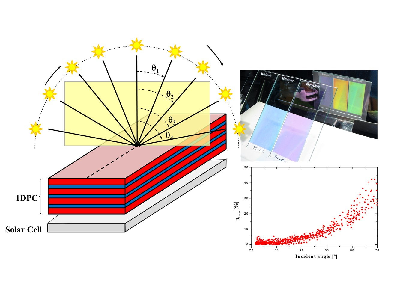
To investigate the angular incoming irradiation on the optical coupling effect between the 1DPC and the solar cell, the photocurrent generated by the prototype under outdoor conditions was measured, obtaining more than 2000 experimental data. The location where the experiments were carried out was Seville (Spain), with latitude 37.39° and longitude −5.97°, during autumn. Two similar prototypes were installed: a solar cell with 1DPC coupled on top and an identical solar cell without 1DPC, which served as a reference sample.
The photocurrent of both devices was measured. The first remarkable evidence was that when the incoming radiation to the devices was normal, both signals were proportional, as expected. However, this correlation was lost during the sunrise and sunset, due to the high incident angles for the incoming radiation irradiance. Optical coupling losses , due to the 1DPC performance, were beyond those expected under the design conditions, as defined in Equation (4) and plotted in Figure 6.
where I1DPC and IC represent the photocurrent measured for 1DPC coupled to the solar cell and the reference solar cell, respectively.
Figure 6 shows that these results were fully aligned with the analysis discussed above for the indoor measurements. As the position of the sun varied along the day, the Bragg peak position shifted from the expected value with normal incident light. If this modification was in the range of +/− 50° and the width of the Bragg peak remained almost constant, there was no significant effect on the photovoltaic device. However, when the incident angle was higher than 50°, the Bragg peak was distorted. Furthermore, the Bragg peak position shifted more than 100 nm. As a consequence, maximum reflectivity was significantly reduced and the original gaussian profile of the Bragg peak was the smoothest. Hence, 1DPC lost their main optical functionalities and the expected optical coupling generated critical losses in the device performance.
3.2. Irrandiance Spectrum Modification Effect
According to our results, higher incident angles induced a nondesired performance of the optical properties of the 1DPC coupled to the solar cell: transparency was significantly reduced, Bragg position shifted to lower energies, and the reflection peak profile was the smoothest, so the main benefits of the photonic crystal dropped. These conditions were critically observed close to dawn and sunset periods, when the irradiance spectrum also changed compared to midday. Scattered light in the atmosphere at these periods of the day modifies the solar spectrum, and this might have affected the optical coupling between 1DPC and the solar cell too. Despite incoming energy on the solar cells at these periods being low for the selected location, this effect should be considered at other locations far away from the equator region.
To determine the criticality of these two parameters (irradiance incident angle and solar spectrum shifting), two identical solar cells, with and without PC1D coupled, were located on a 2-axis tracking to measure again the photocurrent generated. The tracker modified its position quickly, from −70° to 70°, monitoring all measurements in a short period of time, thus allowing us to assume that the solar spectrum did not change significantly during the test.
Results obtained from this test were compared with those obtained from the fixed structure (Figure 7). Data support the previous discussion: when the incident angle was higher than 50°, the losses observed in the solar cell coupled with the 1DPC were significant. At these operational conditions, the expected benefits of the crystal photonics are converted into undesired drawbacks. Effects derived from the irradiance spectrum shifting at dawn and sunset were secondary when compared with the Bragg peak position and its consequence for the optical coupling of the 1PCD. It is also important to point out that monitoring data from the samples installed on a fixed structure or into a 2-axis tracking system were coincident.
Thus, we have demonstrated that, according to Lambert’s law, the photocurrent generated by the photovoltaic device is proportional to the cosine of the angle of incidence of the incoming radiation. However, when optical elements, such as the photonic crystal, are considered in the photovoltaic prototype design, predicted losses by Lambert’s law must be updated to consider the optical decoupling between both elements. This combined effect predicts a reduction in the irradiation cone to maximize the photocurrent of the solar cell under outdoor conditions.
3.3. Polarization Effect
In addition, irradiation is not only described upon its spectrum or the sun position elevation. The state of the light is thus completely defined only when polarization and its dependence are well known. Angular modification had implications on the scattering of polarized light in photonic crystals [30,31,32]. Thus, when a 1DPC is designed for solar applications, design specifications must consider not only the solar spectrum at normal incidence but also angular and polarization dependence. Solar radiation does not have a preferential orientation in the electric field of the light; it is called natural polarization. When this natural polarization is partially reflected by a dielectric material, the degree of polarization of both the reflected and the transmitted light changes: reflected light gets fully polarized in the perpendicular plane of incoming radiation, while transmitted light has higher intensity and the nature of polarization is partially linear.
Photonic crystals coupled to solar cells were located in the back side of the front glass of the device. Thus, despite solar radiation being naturally polarized, light incoming on the 1DPC was partially polarized. As photonic crystals modified the polarization nature of the light, either by reflection or transmission, performance of the solar cell coupled to this optical component might be affected. To investigate the influence of this polarization shift, the angular dependence of the reflection of the light by 1DPC was measured, considering natural and linear polarization (Figure 8).
At low incident angles, there was a coincidence between linear and natural reflected light. This means that with the normal incident direction or low incident angles, reflectivity was independent of the polarization. However, when the incident angle increased, there was a difference in intensity between light with linear polarization reflected and natural light, but the Bragg peak position remained almost constant. At higher incidence angles, due to the periodic structure of the photonic crystal, it was possible to create spectral selective mirrors that were polarization dependent. Polarization affected the photovoltaic device in terms of the intensity of the light reflected or transmitted, but there was no dependence on the Bragg peak shift observed previously. These results were in good concordance with Equations (3)–(5). Angular reflection modified polarized light scattering in plasmonic structures, and this opens an interesting portfolio of applications like splitters.
4. Conclusions
In this research, the optical coupling between 1D photonic crystals and solar cells was analyzed.
Outdoor measurements revealed three potential dependence factors: (a) incident angle; (b) irradiance spectrum; and (c) natural and linear polarization of the incoming light. We demonstrated that the most relevant factor, from a photovoltaic effect point of view, was the incident angle variation due to the sun shift throughout the day. Solar irradiance harvesting enhancement was observed when the elevation angle of the sun was between 50° and normal incidence. Out of this angle range, optical performance dropped as a consequence of optical decoupling with the solar cell spectral response: Bragg peak intensity was significantly reduced, Bragg peak position shifted and remained out of the design specifications, and the gaussian profile of the Bragg peak disappeared for high incident angles. All of this negatively affected the efficiency of the photovoltaic device coupled to 1DPC. As a main conclusion, not only should the normal incident light conditions be considered, but also the influence of these environment conditions should be controlled at the design phase of the device to ensure the proper performance during the operational phase.
Polarization of the incoming radiation is a second factor that cannot be neglected to estimate the electrical production of the solar cell. It has also been demonstrated that linear polarization and natural polarization exhibit different behavior from the point of view of the reflectivity. This change of intensities was related to the photocurrent generated by the photovoltaic device.
The use of 1D photonic crystal in solar applications opens a new portfolio of applications, especially for solar thermal energy hybridization (beam splitter) and photovoltaic devices (transparent modules for building integrated application). These results support the design of these optical filters and to identify critical tolerance to evaluate the performance of the full device in real operating conditions.
Author Contributions
Conceptualization, J.M.D.-S. and I.L.-B.; methodology, J.M.D.-S. and I.L.-B.; software, J.M.D.-S.; validation, J.M.D.-S. and I.L.-B.; formal analysis, J.M.D.-S. and I.L.-B.; investigation, J.M.D.-S. and I.L.-B.; resources, J.M.D.-S.; data curation, J.M.D.-S. and I.L.-B.; writing—original draft preparation, J.M.D.-S. and I.L.-B.; writing—review and editing, J.M.D.-S. and I.L.-B.; visualization, J.M.D.-S. and I.L.-B.; supervision, I.L.-B.; project administration, J.M.D.-S.; and funding acquisition, J.M.D.-S. All authors have read and agreed to the published version of the manuscript.
Funding
This research received no external funding.
Conflicts of Interest
The authors declare no conflict of interest.
References
- Yablonovitch, E. Inhibited spontaneous emission in solid-state physics and electronics. Phys. Rev. Lett. 1987, 58, 2059–2062. [Google Scholar] [CrossRef] [PubMed] [Green Version]
- John, S. Strong localization of photons in certain disordered dielectric superlattices. Phys. Rev. Lett. 1987, 58, 2486–2489. [Google Scholar] [CrossRef] [PubMed] [Green Version]
- McMillan, J.F.; Yang, X.; Panoiu, N.C.; Osgood, R.M.; Wong, C.W. Enhanced simulated scattering in slow-light photonic crystals waveguides. Opt. Lett. 2006, 31, 1235–1237. [Google Scholar] [CrossRef] [PubMed] [Green Version]
- Takashashi, Y.; Inui, Y.; Chihara, M.; Asano, T.; Terawaki, R.; Noda, S. High-Q resonant modes in a photonic crystal heterostructure nanocavity and applicability to a Raman silicon laser. Phys. Rev. B 2013, 88. [Google Scholar] [CrossRef] [Green Version]
- Knight, J.C. Photonic crystals fibers. Nature 2003, 424, 847–851. [Google Scholar] [CrossRef]
- Fan, S.; Villeneuve, P.R.; Joannopoulos, J.D.; Haus, H.A. Channel drop filters in photonic crystals. Opt. Express 1998, 3, 4–11. [Google Scholar] [CrossRef]
- Reader-Harris, P.; Ricciardi, A.; Krauss, T.; di Falco, A. Optical guided mode resonance filter on a flexible substrate. Opt. Express 2013, 21, 1002–1007. [Google Scholar] [CrossRef] [Green Version]
- Quan, Q.; Loncar, M. Deterministic design of wavelength scale, ultra-high Q photonic crystals nanobeam cavities. Opt. Express 2011, 19, 18529–18542. [Google Scholar] [CrossRef] [Green Version]
- Sekoguchi, H.; Takahashi, Y.; Asano, T.; Noda, S. Photonic crystal nanocavity with a Q-factor of 9 million. Opt. Express 2014, 22, 916–924. [Google Scholar] [CrossRef]
- Zhang, Z.; Zhang, L.; Hedhili, M.N.; Zhang, H.; Wang, P. Plasmonic gold nanocrystals coupled with photonic crystal seamlessly on TiO2 nanotube photoelectrodes for efficient visible light photoelectrochemical water splitting. Nano Lett. 2013, 13, 14–20. [Google Scholar] [CrossRef]
- Alabastri, A.; Toma, A.; Malerba, M.; de Angelis, F.; Proietti Zaccaria, R. High temperature nanoplasmonics: The key role of nonlinear effects. Photon 2015, 2, 115–120. [Google Scholar] [CrossRef]
- Das, R.; Jha, R. Highly sensitive plasmonic temperature sensor based on photonic crystal surface plasmon waveguide. Plasmonics 2013, 8, 515–521. [Google Scholar]
- Nazir, A.; Panaro, S.; Proietti Zaccaria, R.; Liberale, C.; de Angelis, F.; Toma, A. Fano coil-type resonance for magnetic hot-spot generation. Nano Lett. 2014, 14, 3166–3171. [Google Scholar] [CrossRef]
- Nikolaenko, A.E.; Papasimakis, N.; Atmatzakis, E.; Luo, Z.; Shen, Z.X.; de Angelis, F. Nonlinear graphene metamaterials. Appl. Phys. Lett. 2012, 100, 181109. [Google Scholar] [CrossRef] [Green Version]
- Kauranen, M.; Zayats, A.V. Nonlinear plasmonics. Nat. Photon. 2012, 6, 737–748. [Google Scholar] [CrossRef]
- Maidecchi, G.; Gonella, G.; Proietti Zaccaria, R.; Moroni, R.; Anghinolfi, L.; Giglia, A. Deep ultraviolet plasmon resonance in aluminum nanoparticle arrays. Nano 2013, 7, 5834–5841. [Google Scholar] [CrossRef] [PubMed]
- Zaccaria, R.P. Butterfly wing color: A photonic crystal demonstration. Opt. Laser Eng. 2016, 76, 70–73. [Google Scholar] [CrossRef]
- Teyssier, J.; Saenko, S.V.; van der Marel, D.; Milinkovitch, M.C. Photonic crystals cause active colour change in chameleons. Nat. Commun. 2015, 6, 7638. [Google Scholar] [CrossRef] [Green Version]
- Debije, M.G.; Verbunt, P.P.C. Thirty years of luminescent solar concentrator research: Solar energy for the built environment. Adv. Energy Mater. 2012, 2, 12–35. [Google Scholar] [CrossRef]
- Zhu, R.; Kumar, A.; Yang, Y. Polarizing organic photovoltaics. Adv. Mater. 2011, 23, 4193–4198. [Google Scholar] [CrossRef]
- Jimenez-Solano, A.; Delgado-Sanchez, J.M.; Calvo, M.E.; Miranda-Muñoz, J.M.; Lozano, G.; Sancho, D.; Sanchez-Cortezon, E.; Miguez, H. Design and realization of transparent solar modules based on luminescent solar concentrators integrating nanostructures photonic crystals. Prog. Photovolt. Res. Appl. 2015, 23, 1785–1792. [Google Scholar] [CrossRef] [PubMed] [Green Version]
- Li, C.-Z.; Liu, S.-B.; Kong, X.-K.; Zhang, H.-F.; Bian, B.-R.; Zhang, X.-Y. A novel comb-like plasma photonic crystal filter in the presence of evanescent wave. IEEE Trans. Plasma Sci. 2011, 39, 1969–1973. [Google Scholar] [CrossRef]
- Mahmoud, M.Y.; Bassou, G.; Taalbi, A.; Chekroun, Z.M. Optical channel drop filters based on photonic crystal ring resonators. Opt. Commun. 2012, 285, 368–372. [Google Scholar] [CrossRef]
- O’Brien, P.G.; Yang, Y.; Chutinan, A.; Mahtani, P.; Leong, K.; Puzzo, D.P.; Bonifacio, L.D.; Lin, C.-W.; Ozin, G.A.; Kherani, N.P. Selectively transparent and conducting photonic crystal solar spectrum splitters made of alternating sputtered indium-tin-oxide and spin-coated silica nanoparticle layers for enhanced photovoltaics. Sol. Energy Mater. Sol. Cells 2012, 102, 173–183. [Google Scholar]
- Shockley, W.; Queisser, H.J. Detailed balance limit of efficiency of p-n junction solar cells. Appl. Phys. Lett. 1961, 32, 510–519. [Google Scholar] [CrossRef]
- Peters, M.; Goldschmit, J.C.; Loper, P.; Grob, B.; Upping, J.; Dimroth, F.; Wehrspohn, R.B.; Blasi, B. Spectrally-selective photonic structures for PV applications. Energies 2010, 3, 171–193. [Google Scholar] [CrossRef]
- Lopez-Lopez, C.; Colodrero, S.; Calvo, M.E.; Miguez, H. Angular response of photonic crystal based dye sensitized solar cell. Energy Environ. Sci. 2013, 6, 1260–1266. [Google Scholar] [CrossRef] [Green Version]
- ISO. Glass in Building—Determination of Light Transmittance, Solar Direct Transmittance, Total Solar Energy Transmittance, Ultraviolet Transmittance and Related Glazing Factors; ISO: Geneva, Switzerland, 2003. [Google Scholar]
- Katsidis, C.C.; Siapkas, D.I. General transfer-matrix method for optical multilayer systems with coherent, partially coherent, and incoherent interface. Appl. Opt. 2002, 41, 3978–3987. [Google Scholar] [CrossRef]
- Lousse, V.; Suh, W.; Kilic, O.; Kim, S.; Solgaard, O.; Fan, S. Angular and polarization properties of a photonic crystal slab mirror. Opt. Express 2004, 12, 1575–1582. [Google Scholar] [CrossRef]
- Zhang, Z.M.; Hanssen, L.M.; Datla, R.U. Polarization-dependent angular reflectance of silicon and germanium in the infrared. Infrared Phys. Technol. 1996, 37, 539–546. [Google Scholar] [CrossRef]
- Kim, S.; Hadzialic, S.; Sudbo, A.S.; Solgaard, O. Reflectivity and polarization dependence of polysilicon single-film broadband photonic crystal micro-mirrors. Opt. Express 2012, 20, 6306–6315. [Google Scholar] [CrossRef] [PubMed] [Green Version]
Figure 1.
(a) One-dimensional photonic crystal (1DPC) designed to minimize solar cell overheating by reflecting nonabsorbed infrared photons. (b) 1DPC designed to act as back spectral selective mirror or beam splitter: Visible solar spectrum is reflected. Dashed red line: photonic crystal transmittance; blue dots: silicon solar cell spectral response.


Figure 2.
(a) 1DPC samples processed by DC sputtering during the calibration process. Modification in the layer thickness induced different reflection and transmission spectra, and consequently, color varied from one sample to another. (b) Reflectance spectrum of each sample (from left to right: PC1-03, PC-02, and PC-04), explaining that the color shifted as a function of the dielectric layer thickness.

Figure 3.
(a) Reflectance modeling response from the objective 1DPC and picture of one of the prototypes tested. (b) Refractive index measured with one ellipsometer during the calibration process.
Figure 3.
(a) Reflectance modeling response from the objective 1DPC and picture of one of the prototypes tested. (b) Refractive index measured with one ellipsometer during the calibration process.

Figure 4.
Transmittance of 1DPC as a function of the incident angle. As incident angle is increased, Bragg peak is shifted to a lower wavelength.
Figure 4.
Transmittance of 1DPC as a function of the incident angle. As incident angle is increased, Bragg peak is shifted to a lower wavelength.

Figure 5.
(a) Bragg peak position shifting as function of the incident angle; and (b) transparency data obtained from transmittance curves versus incident irradiation angle.
Figure 5.
(a) Bragg peak position shifting as function of the incident angle; and (b) transparency data obtained from transmittance curves versus incident irradiation angle.

Figure 6.
Experimental dependence observed for the optical coupling losses as function of the incident angle.
Figure 6.
Experimental dependence observed for the optical coupling losses as function of the incident angle.

Figure 7.
Losses derived from the 1DPC and solar cell optical coupling measured into a 2-axis tracking system, to avoid the effect of irradiance spectrum modification during the day. Red circles represent data collected at the fixed structure (Section 3.1), while blue diamonds correspond to data collected from the 2-axis tracking experiment (Section 3.2).

Figure 8.
Incident angle dependency of PC1D as a function of the polarization of the incoming radiation. Solid lines correspond to natural polarization light, and open circles refer to linear polarization data.
Figure 8.
Incident angle dependency of PC1D as a function of the polarization of the incoming radiation. Solid lines correspond to natural polarization light, and open circles refer to linear polarization data.


Table 1.
Properties of 1DPC fabricated during calibration process.
| Sample ID | Layer Sequence | Dielectric Material 1: SiO2 | Dielectric Material 2: TiO2 | ||
|---|---|---|---|---|---|
| Thickness [nm] | Refractive Index at 600 nm | Thickness [nm] | Refractive Index at 600 nm | ||
| Objective | 1 21 21 21 21 21 21 | 100 | 1.41 | 70 | 2.32 |
| PC-03 | 1 21 21 21 21 21 21 | 90 | 1.41 | 50 | 2.32 |
| PC-02 | 1 21 21 21 21 21 21 | 140 | 1.41 | 70 | 2.32 |
| PC-04 | 1 21 21 21 21 21 21 | 70 | 1.41 | 50 | 2.32 |
Table 2.
Silicon solar cell datasheet.
| Irrandiance (W/m2) | 1000 |
| Temperature (°C) | 25.4 |
| Mismatch corrected | Yes |
| Jsc (mA/cm2) | 32.6 |
| Voc (mV) | 591 |
| FF (%) | 77.2 |
| Efficiency | 14.9 |
| Source | IEC 60904-9 |
| Contact Laboratory | Radboud University Nijmegen |
© 2020 by the authors. Licensee MDPI, Basel, Switzerland. This article is an open access article distributed under the terms and conditions of the Creative Commons Attribution (CC BY) license (http://creativecommons.org/licenses/by/4.0/).
Share and Cite
MDPI and ACS Style
Delgado-Sanchez, J.M.; Lillo-Bravo, I. Angular Dependence of Photonic Crystal Coupled to Photovoltaic Solar Cell. Appl. Sci. 2020, 10, 1574. https://doi.org/10.3390/app10051574
AMA Style
Delgado-Sanchez JM, Lillo-Bravo I. Angular Dependence of Photonic Crystal Coupled to Photovoltaic Solar Cell. Applied Sciences. 2020; 10(5):1574. https://doi.org/10.3390/app10051574
Chicago/Turabian StyleDelgado-Sanchez, J. M., and I. Lillo-Bravo. 2020. "Angular Dependence of Photonic Crystal Coupled to Photovoltaic Solar Cell" Applied Sciences 10, no. 5: 1574. https://doi.org/10.3390/app10051574
Note that from the first issue of 2016, this journal uses article numbers instead of page numbers. See further details here.