Axial and Bending Bearing Capacity of Double-Steel-Concrete Composite Shear Walls


1
School of Transportation Science and Engineering, Beihang University, Beijing 100191, China
2
Department of building structure, China Nuclear Power Engineering Co., LTD, Beijing 100840, China
3
School of Civil Engineering, Qingdao University of Technology, Qingdao 266033, China
*
Author to whom correspondence should be addressed.
Appl. Sci. 2020, 10(14), 4935; https://doi.org/10.3390/app10144935
Submission received: 31 May 2020
/
Revised: 8 July 2020
/
Accepted: 15 July 2020
/
Published: 17 July 2020
(This article belongs to the Special Issue Architectural Structure)
Abstract
:Double steel-concrete composite shear wall is a novel composite structure. Due to its good mechanical properties, it has been considered as a substitute for reinforced concrete walls in nuclear facilities, marine environmental structures, and high-rise buildings. However, the design method of the double-steel concrete composite shear wall is lacking. The purpose of this paper is to propose the bending capacity formula under large and small eccentric loads. By summarizing the test results of 49 steel-concrete composite double shear walls under cyclic loading from different studies, it was found that the bending failure of double-steel-concrete composite shear walls was featured by the concrete crushing at the bottom. A finite element model was established and it could simulate the axial and bending performance of double steel-concrete composite shear walls reasonably well. According to the experimental results and FE analysis, the primary assumptions for calculating the axial and bending bearing capacity of the double steel-concrete composite shear walls were proposed. Based on these assumptions, the bearing capacity formulas were derived according to the equilibrium theory of the cross section. The calculation results obtained by the bearing capacity formulas were in good agreement with the test results.
1. Introduction
Double-steel-concrete composite shear walls (SC walls) mainly consist of two surface steel plates connected by tie bars and filled with concrete. To prevent the buckling of the surface plates and ensure collaborative work between the concrete and steel plates; studs, stiffeners, and other connections are used, except for tie bars. SC walls are developed to reduce wall thickness, to enhance constructability, and to make rapid construction possible by eliminating the use of formwork and reinforcing bars. The filled concrete prevents the early buckling of steel plates, while the steel plates provide the confinement on the concrete, so the SC walls are characterized to have high strength and sufficient ductility for compressive and shear loading. Therefore, the composite effect of steel plates and concrete gives the SC walls significant advantages over the traditional shear walls, such as reinforced concrete shear walls, single steel plate, concrete composite shear walls, profile steel-reinforced concrete composite shear walls, etc.
Previously, the structural characteristics of SC walls have already been studied experimentally and numerically. Depending on the structure, SC walls can be divided into two types. The first type is the SC wall with bending stiffener attached at the edge region, which was subjected to shear failure. The experiments of the first type of SC walls were mainly finished in Japan (e.g., Usami et al. [1], Takeuchi et al. [2], Niwa et al. [3], Ozaki et al. [4], Kitano et al. [5], Funakoshi et al. [6]). The other type is the SC wall without bending stiffener was subjected to bending failure, and the experiments were mainly finished in China and Korea (e.g., Tae-Sung Eom et al. [7], Wu et al. [8], Nie et al. [9,10], Ji et al. [11], Tian et al. [12]). All the studies and experiments indicated that the SC walls had high strength, good ductility, and high energy-dissipation. In recent years, the construction of CAP1400 nuclear power plant in China has promoted the research progress of SC walls in nuclear engineering, such as Guo et al. [13], Yang et al. [14], Liu et al. [15], Li et al. [16], and Li et al. [17]. Lin et al. [18] tested 12 buckling-restrained shear panel dampers which were equipped with demountable steel-concrete composite restrainers. The influence of key design parameters on seismic behavior was studied and design equations for calculating elastic stiffness and ultimate strength were proposed. Zhao et al. [19] experimentally studied the cyclic behavior of two half-scale concrete stiffened steel plate shear wall specimens including the traditional and the innovation. Both specimens showed highly ductile behavior and stable cyclic yielding performance, and some suggestions for the design were also given based on the experiment results. Behnoosh Rassouli et al. [20] investigated experimentally and numerically the behavior of concrete stiffened steel plate shear wall using precast light weight concrete panels, and three specimens were tested under quasi-static cyclic load. The test results show that the CSPSW can reduce the seismic mass and improve the behavior of steel structures.
To date, some work has been conducted on the calculation method for the axial and bending bearing capacity of SC walls. For example, Varma et al. [21] developed a mechanics model and a detailed nonlinear finite element model, and the two modeling methods were applied to develop a conservative interaction surface in principal forces space that can be used to design or evaluate the adequacy of SC walls subjected to any combinations of in-plane forces. Tae-Sung Eom et al. [7] tested slender isolated walls and coupled walls subjected to cyclic loading. Based on their tested results, they developed the calculation method for the load-carrying capacity. Bo Wu et al. [8] calculated the lateral loading capacity of the SC walls based on the concept of the combined strength of new and old concrete. Ji et al. [11] proposed simplified formulas used to evaluate the flexure strength of the SC walls. However, all the calculation methods were derived using plastic stress distributions at the cross sections, which was the same as [22], and only suitable for calculating the compression members with large eccentricity. When applying to a small eccentric load, the methods would cause larger calculation errors, because the steel plates in tension did not reach the yield strength. Xiaowei Ma et al. [23] developed a model for the elastic and plastic analysis of the axial force-moment capacity of SC walls and analyzed the M-φ curve and the axial force and moment curve. They derived the formula for axial force-moment based on the key factors gained by numerical calculation and parameter analysis. However, the factors were complex and did not take into account the effects of structural measures, so the formula cannot be used widely in practical engineering. Jianguo Nie et al. [10] used the strip method to deduce the calculation formula of normal section bearing capacity, which applied to both small and large eccentric load. However, the strip method was complex and the ultimate compression strain of the concrete was taken as 0.0033, which was inconsistent with the confinement effect of steel plates on the concrete. Papanikolaou et al [24] proposed a confinement-sensitive plasticity constitutive model for concrete in triaxial compression. It incorporates a three-parameter loading surface, uncoupled hardening and softening functions, following the accumulation of plastic volumetric strain and a nonlinear Lode-angle-dependent plastic potential function. Skalomenos et al. [25] created an accurate nonlinear finite element model with the ATENA software, and the influences of different parameters were studied.
Due to the excellent strength and ductility, SC Walls have already been applied to a lot of structures requiring high resistance against severe loads since the 1980s, such as nuclear facilities, or marine environment structures. In China, SC walls are mainly used in high-rise buildings, including Yancheng TV Tower [26] and Guangzhou TV Tower. Due to the lack of detailed design codes, the above structures were mainly carried out based on the overall concept of the structure regarding other composite structures, so a reasonable and correct design method for SC Walls is urgently needed. In this paper, based on the experimental results of 49 SC walls and the results of numerical analysis, the bending failure characteristic of SC walls was studied and summarized, and a primary assumption of SC walls was put forward. Then according to the ultimate equilibrium theory of the cross section, the axial and bending capacity formula was deduced and compared with the existing experimental results.
2. Experimental Results Analysis
SC walls were conceived initially in Japan in the 1980s. Extensive research has been done in many countries to study the behavior and failure modes of SC walls. For example, Eom et al. [7] tested three isolated walls and two coupled walls subjected to cyclic lateral loading. The specimen named DSCW1C in the test failed due to outward buckling of the steel plates and subsequent fracture of the vertical weld joint, followed by the filled concrete crushing and tie bars fracture. Nie et al. [10] tested nine SC wall specimens with different shear span ratios. All the specimens failed due to the buckling of the steel plates and the filled concrete crushing. Ji et al. [11] tested five slender rectangular wall specimens subjected to axial forces and lateral cyclic loading. The specimens failed in a flexural mode, characterized by local buckling of the steel tubes and plates, fracture of the steel tube, and concrete crushing at the wall base. Besides, the tested indicated that the average strain distribution of the surface steel plates agreed with the plane assumption within the range of 300mm above the wall base. Tian [12] tested nine SC wall specimens with the rectangular cross section. The experiment showed all the specimens failed due to the steel plate buckling and concrete crushing.
The following conclusions are obtained by analyzing and summarizing the experimental results of the existing researches.
- The bending failure characteristics of the SC wall are similar. Steel plate at the bottom of the SC wall yields first, followed by the buckling of the steel plate and concrete crushing. All SC wall failures are characterized by concrete crushing at embedded columns. When the studs are closely arranged, the steel plate at the bottom of the wall plate yields before buckling.
- Before the load reaches the peak, the average strain distribution of the surface steel plate at a certain height from the wall base is consistent with the plane assumption.
The ratio of the stud spacing (B) to the steel plate thickness (t) has a significant effect on the steel plate buckling, as shown in Table 1. When the B/t ratio is within a certain range, local buckling occurs when the specimen near reaches the ultimate bearing capacity, and the buckling is accompanied by the pull-out of the concrete, indicating that the slippage between the surface steel plate and the filled concrete is small. When calculating the axial and bending bearing capacity of the SC wall, it is assumed that the steel plate and the concrete can be well unified without relative sliding, and when the SC wall reaches the ultimate bearing capacity, the steel plate does not buckle.
Because the concrete in the SC shear wall is wrapped inside the steel plate, variables such as the ultimate compressive strain of concrete and the average strain of concrete in a certain height range are difficult to measure. To verify whether the strain conforms to the plane assumption in more cases and obtain the strain of the concrete inside the wall under ultimate load, a finite element simulation of the specimen in [12] was conducted. Calculations under various design axial compression ratios were carried out to supplement the test results.
3. Numerical Analysis
3.1. FE Model
In the structure of SC walls, the concrete is covered by the surface steel plates, so it is difficult to measure the ultimate compressive strain of the concrete and the average strain. In this paper, the finite element analysis was done using ABAQUS (Dassault Systèmes, Providence, Rhode Island, USA, 2010) to obtain the strain distribution of the concrete, to verify the plane assumption, and to carry out the parametric analysis. There are few experiments on small eccentric compression failure, so the SC walls having small eccentric compression failure were simulated by ABAQUS.
Nonlinear finite element analysis was performed on all samples in [12] using ABAQUS. The reinforcement diagram of a specimen is shown as an example in Figure 1. The upper and lower parts of the SC wall were embedded in the loading beam and the base beam, respectively, for applying the lateral load and anchoring with the foundation. The parameters of specimens are shown in Table 2. Studs were set on the inner surface of the steel plate and tie bars were arranged between the steel plates. In the test, the specimen was fixed on the ground by two long bolts. The concrete grade was C35. The average cube compressive strength was 42.9 MPa, and the Young’s modulus was 33,000 MPa. The average yield strength of the steel plate was 330 MPa, and the Young’s modulus was 206 GPa. The quasi-static method was applied in the loading test. First, the vertical load was applied to the specimen until the design axial compression ratio was achieved. Then a lateral load was applied on the top of the wall. Before yielding, the lateral load increased step by step according to 1/10 of the ultimate load, which was estimated, and one cyclic loading was performed at each step.
The design axial compression ratio (μ) refers to the ratio of the representative value of the load to the design value of the material strength, which can be expressed as follow:
where N is the design value of the axial pressure of the specimen under the action of the representative value of the gravity load. fc is the design value of concrete compressive strength. fy is the design value of the yield strength of the steel plate. Ac and As are the concrete cross section area and the steel plate cross section area, respectively.
The ABAQUS model of specimens taken from [12] is shown in Figure 2. The concrete was modeled with the C3D8R solid element; the steel plate was modeled with the S4R shell element; the tie bar was modeled with the T3D2 truss element, which is similar to [27]. The stud was modeled with the SPRING2 element.
In this paper, a three-way zero-length spring was added between the concrete slab node and the steel plate node at the actual position of the stud. The spring stiffness includes shear stiffness and axial stiffness. Aiming at the shear-slip curve, Ollgaard et al. [28] proposed a calculation model, which has been widely recognized. The shear-slip curve is expressed as:
where s is the slippage. m and n are parameters. Different researchers used Equation (2) to fit the m and n according to their test results. The value of m is generally between 0.4 and 1.5, and the value of n is generally between 0.5 and 2.0. Gattesco and Giuriani [29] conducted two horizontal push-out shear tests of 19 mm diameter stud. Using the Equation (2) proposed by Ollgaard et al. [28] to fit the experimental value of the shear-slip curve in [29], when m = 0.425, n = 0.5, the two coincide. Another parameter that needs to be determined is the ultimate shear strength Vu. The test results of [29] are in good agreement with the calculation results of Eurocode-4 [30]. The equation proposed by Eurocode-4 was applied in this paper to calculate Vu, which is expressed as:
where fu is the ultimate tensile strength of the stud, A is the section area of the stud, d is the diameter of the stud, fck is the compression strength of concrete cylinder, Ecm is the young’s modulus of concrete, , and h is the height of the stud. The relationship between shear force and displacement can be obtained by Equations (1) and (2) and can be used as the nonlinear spring stiffness. According to Luis Pallarés et al. ’s review [31] of the tensile failure of stud, there are generally three types of failure, namely, stud fracture, concrete cone pull-out failure, and concrete column pull-out failure. According to American Concrete Code 318-08 (ACI 318-08), when the diameter of the stud cap is greater than 1.71 times the diameter of the stud rod, there is a 95% probability that the concrete column will not be pulled out. When the length of the stud is greater than 7.5 times the diameter of the stud, the concrete cone will not be pulled out [31]. Therefore, the brittle failure of the concrete can be completely avoided by construction measures. The damage caused by the stud itself breaking is ductile. The bolt is equivalent to a tension member with one end fixed and one end freely stretched, so the stiffness of the stud can be used to calculate the stiffness of the axial spring, which is expressed as follows:
where E is the young’s modulus of the stud, A is the section area of the stud and h is the height of the stud.
The steel plates were embedded in the loading beam and the base beam. The studs and tie bars were embedded in the concrete. The contact feature was used between the elements of the concrete wall and the steel plate that was not inserted in the loading beam and the base beam. The contact properties were frictional contact in the tangential direction and hard contact in the normal direction, respectively. The boundary conditions are shown in Figure 2b. The FE model was fixed on the ground by two springs with the spring stiffness of EA/L, where A and L were the bolt section area and length, respectively. The contact between the base beam and the foundation was simulated by an elastic foundation model. The reaction force coefficient of the concrete foundation is generally 7484.6–14,715 kN/mm3 [32]. In the simulation, the reaction force coefficient was 10,000 kN/mm3. At both ends of the model foundation beam, the horizontal displacement of the wall in and out of the wall was constrained, and the vertical displacement was not constrained. The concrete damaged plasticity model was applied to simulate the behavior of concrete. The energy equivalence principle of Sidiroff was applied to calculate the damage factor. The ideal elastoplastic stress-strain curve was applied to model the behavior of steel plates and tie bars.
3.2. FE Calculation Results
The calculated load-displacement skeleton curves were compared with the experimental results. Comparisons between the experimental result and the calculated result are shown in Figure 3, which presents a good agreement. Besides, the average ratio of the calculated value of ultimate bearing capacity to the experimental value is 1.09; the average ratio of the peak displacement between the calculated value and experimental value is 0.9; the average ratio of the steel yield load and displacement are 0.93 and 1.04, respectively. Therefore, it could be concluded that this modeling method could effectively simulate the mechanical property of SC walls under cyclic loads.
The specimens in [12] were under the same axial compression ratio. To verify whether the strain meets the plane assumption under different axial compression ratios, three representative specimens with different steel contents and shear span ratios are selected, which are specimen SCW1-1 (steel plate thickness is 3 mm, shear span ratio is 1.0), SCW1-2 (steel plate thickness is 3 mm, shear span ratio is 1.5) and specimen SCW1-4 (steel plate thickness is 4 mm, shear span ratio is 1.0). Nine FE models under different axial compression ratios were simulated using ABAQUS. The results are as follows:
- Average strain distribution of the cross section
As shown in Figure 4, when the load reaches the ultimate value, under different axial compression ratios, steel ratios and shear span ratios, the average strain at the bottom cross section of the wall is consistent with the plane assumption.
- 2.
- Ultimate compression strain of the concrete
There are few studies on the ultimate compression strain of the confined concrete. In this paper, the ultimate compression strain was obtained by ABAQUS analysis. Figure 5 shows the concrete ultimate compression strain of the specimens with different axial compression ratios. In Figure 5, the theoretical value was calculated referring to [34], in which the ultimate compression strain of concrete was defined as the post-peak strain corresponding to the stress valued 0.5fc in the declining part of the stress-strain curve. For the constitutive relationship of concrete under unidirectional load, refer to the constitutive relationship of rectangular steel tube concrete proposed by Han [35]. As shown in Figure 5, the axial compression ratio, steel ratio, and shear-span ratio influence the concrete ultimate compressive strain; the theoretical value approximated to the lower limit of the results calculated by ABAQUS. Therefore, when calculating the axial and bending bearing capacity for SC walls, the confined concrete compression strain could be calculated conservatively according to the above method.
4. Derivation of the Axial and Bending Bearing Capacity
4.1. Basic Assumption
Based on the experimental results and finite element analysis, the basic assumptions for calculating the axial and bending bearing capacity of SC walls are proposed.
- The failure of SC walls is that the outermost concrete in the compression zone reaches the ultimate compressive strain, and the corresponding bearing capacity is taken as the ultimate bearing capacity;
- The surface steel plate and concrete are well combined without slippage;
- The average strain distribution of the wall cross section is consistent with the plane assumption;
- The tensile effect of the concrete is not taken into account;
- The constitutive of the concrete with the confinement of a rectangular steel tube is introduced to describe the behavior of concrete under a uniaxial load, which was proposed by Han [35]. The ultimate compressive strain of concrete corresponded to a stress value of 0.5fcc in the descending part of the stress-strain curve;
- The ideal elastic-plastic constitutive is introduced to describe the behavior of steel plate, ignoring the strain hardening;
- The concrete compressive stress distribution is replaced by equivalent rectangular stress distribution. The equivalent stress is α1fcc and the equivalent compression zone height is x = β1xn. α1 and β1 are equivalent rectangular stress coefficients, which are related to the concrete grade. The values of α1 and β1 are the same as ordinary concrete. fcc is calculated using Equation (5) [34].where fcc is the compressive strength of confined concrete; fc is the compressive strength of the concrete; and ξ1 is the confinement effect coefficient.
The confinement effects of the column plate and the steel plate on concrete are different in SC walls. When the connectors between the surface steel plates are enough, ξ1 can be calculated conservatively using Equation (6).
where As0 is the total cross-section area of the steel plate in the SC wall (including the vertical partition plates); fy is the yield strength of the steel plate; and Ac is the total cross-section area of the concrete in the SC wall.
4.2. Section Simplification
Figure 6a shows the configuration of the SC wall. The components used to resist the bending moment include the web plate, column plate, partition plate, and stiffening steel tube (or profile steel). To simplify the calculation, the cross section is simplified, as shown in Figure 6b. The column plate and stiffening steel are simplified to the outermost side of the wall according to the principle of providing the equivalent moment of the cross section centroid axis when the steel yielded. The yield strength of the fringe plate equals the yield strength of the web plate. The web steel plates and partition plates are simplified to web plate according to the principle of equal area.
4.3. Failure Modes
Based on the above assumptions and simplification, the ultimate equilibrium method is applied to derive the axial and bending bearing capacity formula of the SC wall. The balanced failure of the SC wall is defined so that the steel plates in tension reach the yield strength simultaneously when the concrete in the compressive zone reaches the ultimate compressive strain. The relative height of the concrete compressive zone is ξb, which can be calculated by Equation (7) referring to [36]. When ξ ≤ ξb, the steel plates in tension could reach the yield strength when the wall breaks, and the failure mode of the SC wall is called large eccentric compression failure. When ξ > ξb, the steel plates in tension cannot reach the yield strength when the wall breaks; the failure mode of the SC wall is called small eccentric compression failure (as shown in Figure 7).
4.4. Large Eccentric Compression Failure (ξ ≤ ξb)
Figure 8 shows the distribution of the cross-section stress and strain for the large eccentric SC wall. The equilibrium equation of the cross section is described as Equations (8) and (9).
where, N is the design value of the axial force; e is the distance from the axial force to the center of the steel plate in tension; As′ is the area of the steel plate in compression; Nsw is the resultant force of the web plate (stress in compressive direction is defined positive and stress in tensile direction is negative); Msw is the moment of the web plate normal stress about the center of the steel plate in tension (the clockwise direction is defined as positive, the counterclockwise direction is defined as negative); Cc is the resultant of the concrete compressive stress (stress in compressive direction is defined positive and stress in tensile direction is negative); and Mc is the moment of the concrete normal stress about the center of the steel plate in tension (the clockwise direction is defined as positive, the counterclockwise direction is defined as negative).
If ,
If ,
where, xn is the height of the concrete compressive zone; bw is the thickness of the wall web; hf′ is the height of the compression flange; and bf’ is the width of the compression flange.
The stress distribution of the web plate is equivalent to the superimposition of one full plastic stress distribution and a triangle stress distribution, as shown in Figure 9. The triangle stress distribution can be seen as a couple. The couple has a negligible effect on the bearing capacity. For example, the horizontal bearing capacity of SCW1-5 in [12] was 1653.57 kN if the couple was considered. The result was 1653.59 kN if the couple was ignored and the difference was only 0.0012%. Therefore, the couple in Figure 9b can be ignored in the process of calculating the bearing capacity. The formula is simplified as Equations (14) and (15).
4.5. Small Eccentric Compression Failure (ξ > ξb)
Figure 10 shows the distribution of the cross-section stress and strain for the small eccentric SC wall. The equilibrium equations of the section are described as Equations (16) and (17).
where, Ts is the resultant force of the steel plate in tension. Ts is calculated by Equation (15), referring to [36].
where, xnb is the height of the concrete compression zone in the balanced failure mode.
To simplify the calculation, the web plate stress distribution is simplified, as shown in Figure 11. η is used to revise the compression field height, to reduce the simplification error. In this paper, η was calculated using Equation (19). Therefore, Nsw and Msw can be calculated using Equations (20) and (21).
4.6. Verification
The ultimate bearing capacities of 31 specimens in different researches were calculated by Equations (9)–(21). The calculated results are compared with the experimental results, as shown in Figure 12. Since large eccentric compression failure occurred in all the specimens in the references, therefore, the finite element analysis for three small eccentric specimens was carried out using ABAQUS to verify the effectiveness of the calculation formula of small eccentricity, and the results were compared with the theoretical results from the calculation formula of small eccentricity. As shown in Figure 12, the calculated results agree well with the experimental and finite element analysis results. The average ratio of the calculation results to the experimental results of 31 specimens and the results of 3 FE models is 1.054, and the standard deviation is 0.086. Consequently, the above calculation method can predict the axial and bending bearing capacity of SC walls effectively.
Also, for some specimens in [12], it is clear that the calculation results are much lower than the experimental results. This is mainly because the hardening of the steel plate in tension is not considered in the formulas, but the steel plates of some specimens in [12] had reached the strain-hardening range, and even tension fracture appeared.
5. Conclusions
This paper summarized the experimental results of 49 SC walls subjected to cyclic loading. The parameter analysis using ABAQUS was carried out to supplement the experiments. Based on the analysis of the experimental results and finite element analysis results, the calculation method for the axial and bending bearing capacity of SC walls are proposed. The conclusions of this paper are summarized as follows.
- The bending failure of SC walls featured the concrete crushing at the column and the average strain distribution of the wall cross section agreed with the plane assumption.
- When studs meet certain construction requirements, the surface steel plates and filled concrete are unified well, and the bond-slip between them is relatively small.
- The ultimate compressive strain of the concrete can be defined as the post-peak strain corresponding to the stress valued 0.5fcc in the declining part of the stress-strain curve; the constitutive of the concrete with the confinement of a rectangular steel tube is applied to descript the behavior of concrete.
- The basic assumption for calculating the axial and bending bearing capacity of SC walls is put forward and the calculation formula applying to both small and large eccentric load is deduced. The calculated results are compared with the experimental results, which present good agreements.
Author Contributions
Conceptualization, Q.G.; Data curation, P.Z.; Formal analysis, P.Z. and F.K.; Funding acquisition, Q.G.; Investigation, W.Z. and F.K.; Methodology, W.Z. and Y.Y.; Project administration, Q.G. and Y.Y.; Writing—original draft, F.K.; Writing—review & editing, P.Z. All authors have read and agreed to the published version of the manuscript.
Funding
This work was funded by National Natural Science Foundation of China (Grant No. 51778032).
Acknowledgments
This work was supported National Natural Science Foundation of China (Grant No. 51778032). The authors greatly appreciate the financial support.
Conflicts of Interest
The authors declare no conflict of interest. The funders had no role in the design of the study; in the collection, analyses, or interpretation of data; in the writing of the manuscript, or in the decision to publish the results.
References
- Usami, S.; Akiyama, H.; Suzuki, T.; Sekimoto, H.; Kobayashi, M. Experimental study on concrete filled steel shear wall: Part 2 bensing shear test. In Summaries of Technical Papers of Annual Meeting; Structures. II; Architectural Institute of Japan: Tokyo, Japan, 1991; pp. 1661–1662. [Google Scholar]
- Takeuchi, M.; Narikawa, M.; Matsuo, I.; Hara, K.; Usami, S. Study on a concrete filled structure for nuclear power plants. Nucl. Eng. Des. 1998, 179, 209–223. [Google Scholar] [CrossRef]
- Niwa, N.; Sasaki, N.; Akiyama, H.; Narikawa, M.; Hara, K.; Takeuchi, M.; Usami, S. Study on concrete filled steel structures for nuclear power plants: Part 3 outline of bending shear tests. In Summaries of Technical Papers of Annual Meeting; B-2; Structures II; Structural Dynamics Nuclear Power Plants; Architectural Institute of Japan: Tokyo, Japan, 1995; pp. 987–988. [Google Scholar]
- Ozaki, M.; Akita, S.; Osuga, H.; Nakayama, T.; Adachi, N. Study on steel plate reinforced concrete panels subjected to cyclic in-plane shear. Nucl. Eng. Des. 2004, 228, 225–244. [Google Scholar] [CrossRef]
- Kitano, T.; Akita, S.; Nakazawa, M.; Fujino, Y.; Ohta, H.; Yamaguchi, T.; Nakayama, T. Experimental study on a concrete filled steel structure: Part 4 shear tests (outline of the experimental program nad the results). In Summaries of Technical Papers of Annual Meeting; B-2; Structures II, Structural Dynamics Nuclear Power Plants; Architectural Institute of Japan: Tokyo, Japan, 1997; pp. 1057–1058. [Google Scholar]
- Funakoshi, A.; Akita, S.; Matsumoto, N.; Hara, K.; Hara, K.; Hayashi, N. Experimental study on a concrete filled steel structure: Part 7 bending shear tests(outline of the experimental program nad the results). In Summaries of Technical Papers of Annual Meeting; B-2; Structures II; Structural Dynamics Nuclear Power Plants; Architectural Institute of Japan: Tokyo, Japan, 1997; pp. 1063–1064. [Google Scholar]
- Eom, T.-S.; Park, H.-G.; Lee, C.-H.; Kim, J.-H.; Chang, I.-H. Behavior of double skin composite wall subjected to in-plane cyclic loading. J. Struct. Eng. ASCE 2009, 135, 1239–1249. [Google Scholar] [CrossRef]
- Wu, B.; Liu, C.; Zhao, X.; Liu, Q. Experimental study on seismic behavior of double thin skin hybrid walls filled with demolished concrete lumps. J. Build. Struct. 2011, 32, 116–125. [Google Scholar]
- Nie, J.; Tao, M.; Fan, J.; Bu, F.; Hu, H.; Ma, X.; Li, S.; Liu, F. Research advances of composite shear walls with double steel plates and filled concrete. Build. Struct. 2011, 41, 52–60. [Google Scholar]
- Nie, J.; Bu, F.; Fan, J. Experimental research on seismic behavior of low shear-span ratio composite shear wall with double steel plates and infill concrete. J. Build. Struct. 2011, 32, 74–81. [Google Scholar]
- Ji, X.; Jiang, F.; Qian, J. Seismic behavior of steel tube–double steel plate–concrete composite walls: Experimental tests. J. Constr. Steel Res. 2013, 86, 17–30. [Google Scholar] [CrossRef]
- Tian, C.; Cheng, W. Report of the Experimental Research of Steel Plate and Concrete Composite Shear Wall in Htr; Beihang University: Beijing, China, 2013. [Google Scholar]
- Guo, X.; Qiu, L.; Luo, Y.; Li, J.; Dong, N.; Zhang, J. Seismic performance of concrete-filled double skin composite shear wall with opening. J. Harbin Inst. Technol. 2015, 47, 69–76. [Google Scholar]
- Yang, Y.; Liu, J.; Nie, X.; Fan, J. Experimental research on out-of-plane cyclic behavior of steel-plate composite walls. J. Earthq. Tsunami 2016, 10, 1650001. [Google Scholar] [CrossRef] [Green Version]
- Liu, Y.; Yang, Q.; Liu, J.; Liao, Y. Experimental research on axial compressive behavior of shear wall with double steel plates and filled concrete. J. Sichuan Univ. 2016, 48, 83–90. [Google Scholar]
- Li, X.; Li, X.; Shen, L.; Liu, J. Experimental study of composite shear walls with double steel plates and filled concrete for a nuclear island structure under low cyclic loading. J. Beijing Univ. Technol. 2015, 42, 1498–1508. [Google Scholar]
- Li, X.; Li, X. Study on in-plane flexural behavior of double steel plates and concrete infill composite shear walls for nuclear engineering. Eng. Mech. 2017, 34, 43–53. [Google Scholar]
- Lin, X.; Wu, K.; Skalomenos, K.A.; Lu, L.; Zhao, S. Development of a buckling-restrained shear panel damper with demountable steel-concrete composite restrainers. Soil Dyn. Earthq. Eng. 2019, 118, 221–230. [Google Scholar] [CrossRef]
- Zhao, Q.; Astaneh-Asl, A. Cyclic behavior of traditional and innovative composite shear walls. J. Struct. Eng. ASCE 2004, 130, 271–284. [Google Scholar] [CrossRef] [Green Version]
- Rassouli, B.; Shafaei, S.; Ayazi, A.; Farahbod, F. Experimental and numerical study on steel-concrete composite shear wall using light-weight concrete. J. Constr. Steel Res. 2016, 126, 117–128. [Google Scholar] [CrossRef]
- Varma, A.H.; Malushte, S.R.; Sener, K.C.; Lai, Z. Steel-plate composite (sc) walls for safety related nuclear facilities: Design for in-plane forces and out-of-plane moments. Nucl. Eng. Des. 2014, 269, 240–249. [Google Scholar] [CrossRef]
- Japanese Electric Association. Techinical Guidelines for Aseismic Design of Steel Plate Reinforced Concrete Structures-Buildings and Structures; Japanese Electric Association: Tokyo, Japan, 2005; Volume JEAG4618-2005. [Google Scholar]
- Ma, X.; Nie, J.; Tao, M.; Bu, F. Numerical model and simplified formula of axial force-moment capacity of composite shear wall with double steel plates and infill concrete. J. Build. Struct. 2013, 34, 99–106. [Google Scholar]
- Papanikolaou, V.K.; Kappos, A.J. Confinement-sensitive plasticity constitutive model for concrete in triaxial compression. Int. J. Solids Struct. 2007, 44, 7021–7048. [Google Scholar] [CrossRef] [Green Version]
- Skalomenos, K.A.; Hatzigeorgiou, G.D.; Beskos, D.E. Parameter identification of three hysteretic models for the simulation of the response of cft columns to cyclic loading. Eng. Struct. 2014, 61, 44–60. [Google Scholar] [CrossRef]
- Ding, Z.; Jiang, H.; Zeng, J.; Zhang, H.; Du, G. An innovative application of scs composite wall: Structural design of yancheng tv tower. Build. Struct. 2011, 41, 87–91. [Google Scholar]
- Shafaei, S.; Farahbod, F.; Ayazi, A. Concrete stiffened steel plate shear walls with an unstiffened opening. Structures 2017, 12, 40–53. [Google Scholar] [CrossRef]
- Ollgaard, J.G.; Slutter, R.G.; Fisher, J.W. Shear Strength of Stud Connectors in Lightweight and Normal-Weight Concrete, AISC Eng’g Jr., April 1971 (71-10). 1971, pp. 55–64. Available online: https://preserve.lehigh.edu/cgi/viewcontent.cgi?article=3009&context=engr-civil-environmental-fritz-lab-reports (accessed on 15 July 2020).
- Gattesco, N.; Giuriani, E. Experimental study on stud shear connectors subjected to cyclic loading. J. Constr. Steel Res. 1996, 38, 1–21. [Google Scholar] [CrossRef]
- The European Committee for Standardization (CEN). Design of Composite Steel and Concrete Structures, Part 2: Composite Bridges; CEN: Brussels, Belgium, 1997. [Google Scholar]
- Pallarés, L.; Hajjar, J.F. Headed steel stud anchors in composite structures, part II: Tension and interaction. J. Constr. Steel Res. 2010, 66, 213–228. [Google Scholar] [CrossRef]
- CSSC. Calculation of Beam and Rectangular Plate on Elastic Foundation; National Defense Industry Press: Beijing, China, 1983. [Google Scholar]
- Guo, Q. Report of the Theoretical Research of the Seismic Performance of High-Temperature Gas-Cooled Reactor (HTR-PM) Steel-Concrete Composite Shear Wall; Beihang University: Beijing, China, 2013. [Google Scholar]
- MOHURD. Code for Design of Concrete Structures; China Architecture & Building Press: Beijing, China, 2010; Volume GB50010-2010.
- Han, L. Concrete Filled Steel Tube Structure-Theory and Practice; Science Press: Beijing, China, 2007. [Google Scholar]
- Teng, Z.; Zhu, Z. Concrete Structure and Masonry Structure; China Architecture & Building Press: Beijing, China, 2003. [Google Scholar]
Figure 1.
Diagrams of SC walls (SCW1-2) in [33].
Figure 1.
Diagrams of SC walls (SCW1-2) in [33].
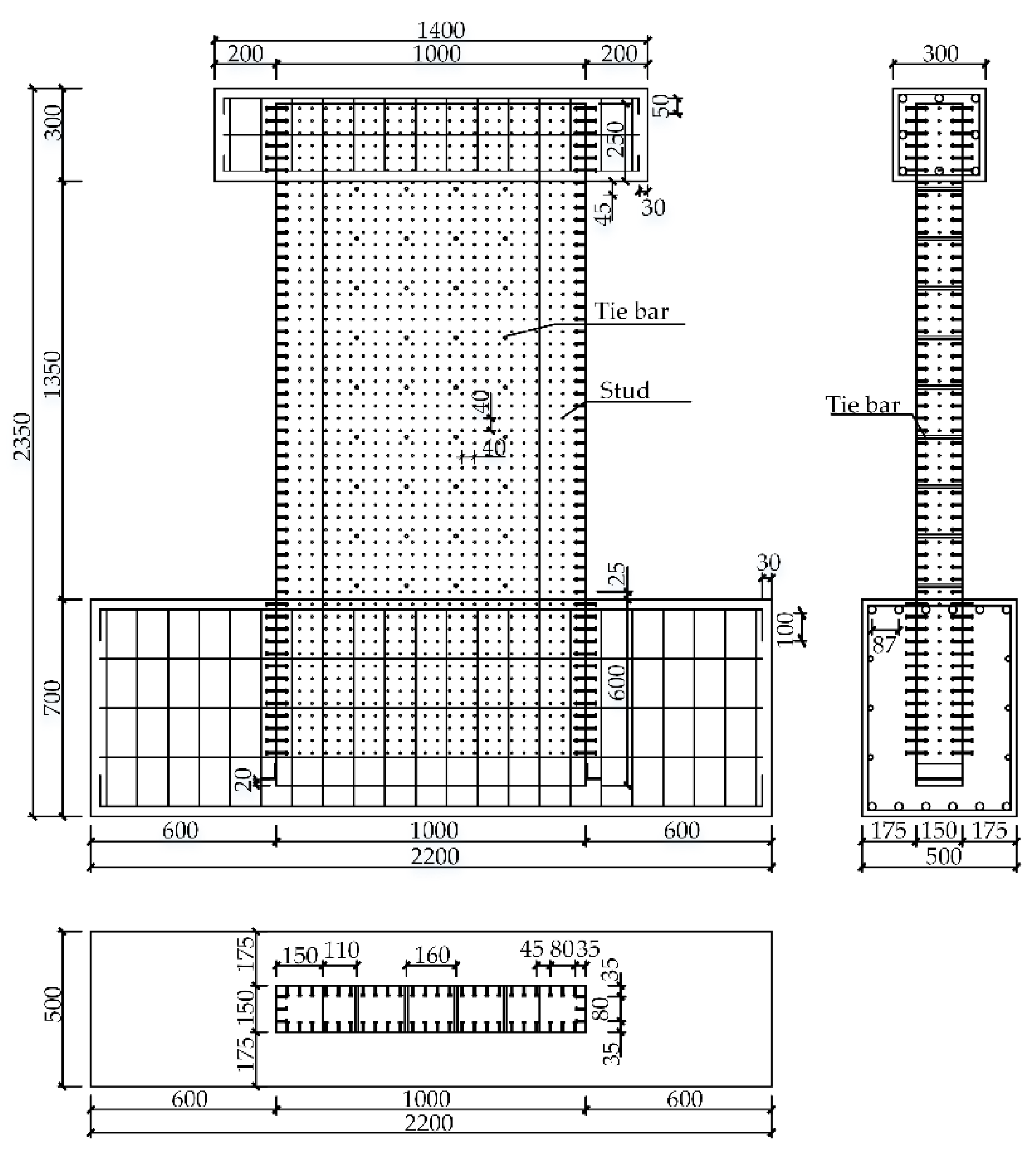
Figure 2.
FE model in ABAQUS. (a) FE models; (b) Boundary conditions of FE models.
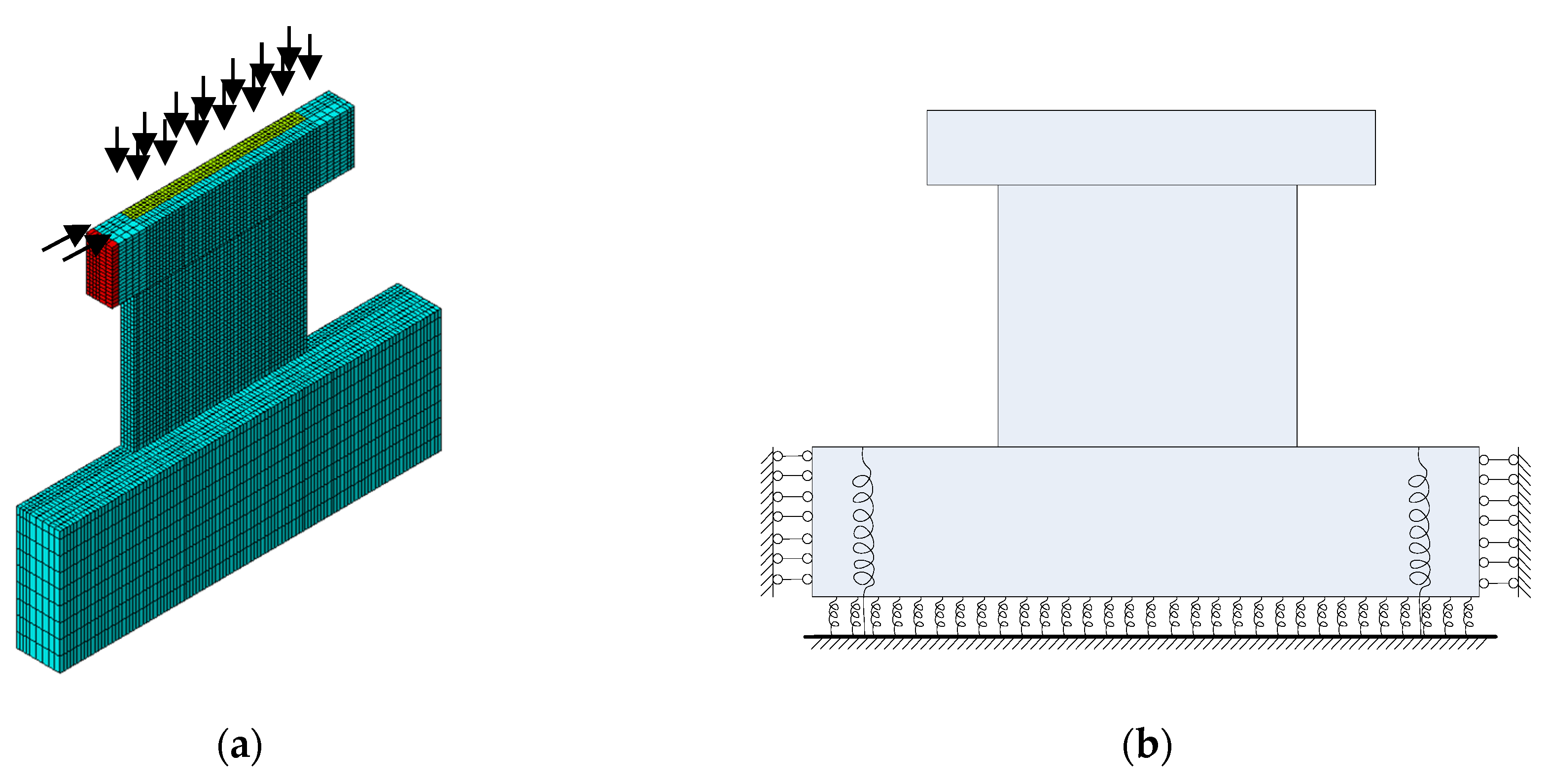
Figure 3.
Comparisons between the experimental result and the calculated result.

Figure 4.
Vertical strain distribution at the wall base for specimens at ultimate load under different axial load ratios (μ is the axial compression ratio).
Figure 4.
Vertical strain distribution at the wall base for specimens at ultimate load under different axial load ratios (μ is the axial compression ratio).

Figure 5.
Maximum concrete compression strain versus axial compression ratio of specimens at ultimate load.
Figure 5.
Maximum concrete compression strain versus axial compression ratio of specimens at ultimate load.

Figure 6.
Simplification of the cross section for SC walls. (a) The general section structure; (b) Cross section simplification.
Figure 6.
Simplification of the cross section for SC walls. (a) The general section structure; (b) Cross section simplification.
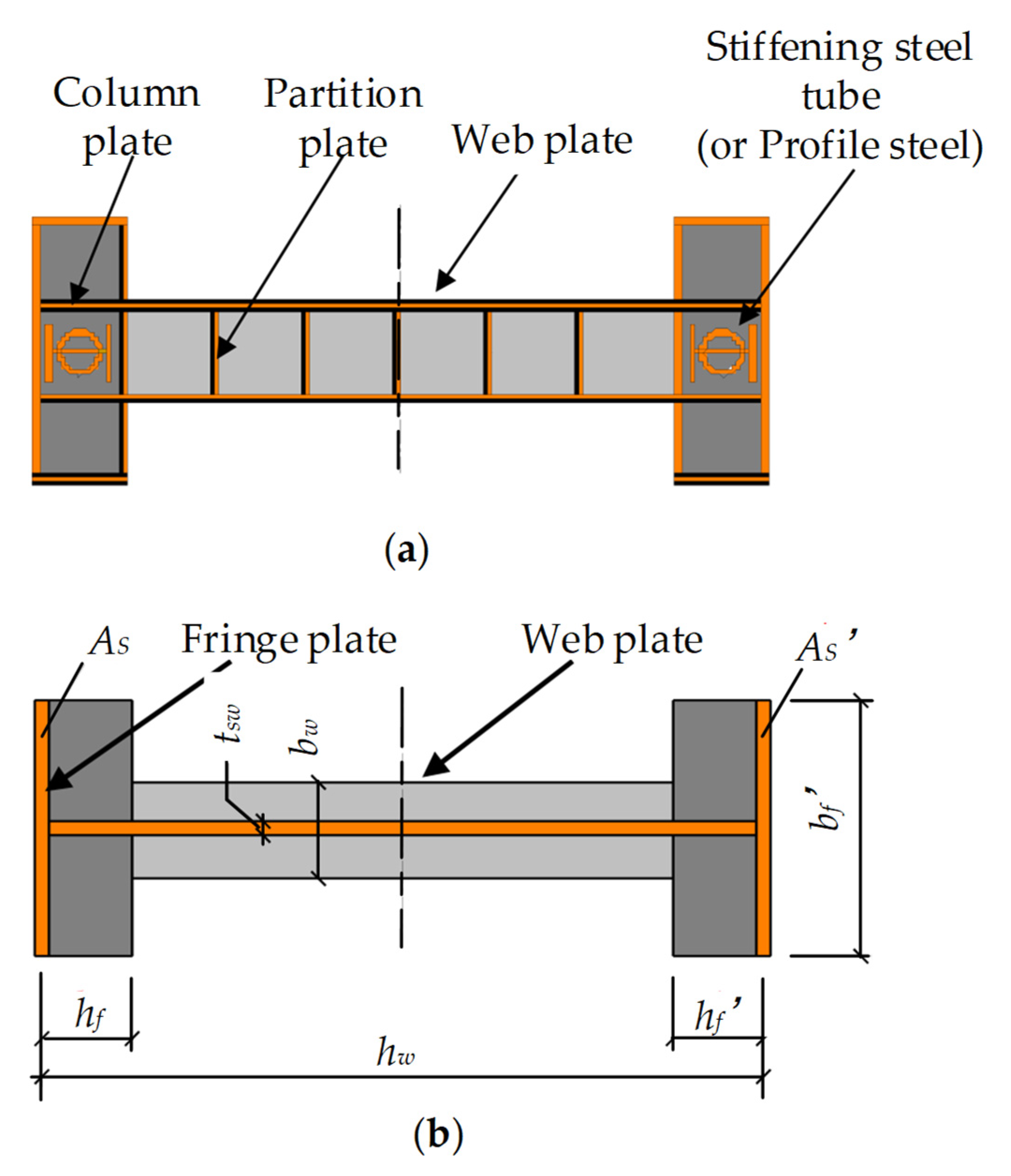
Figure 7.
The strain distribution of the SC walls.
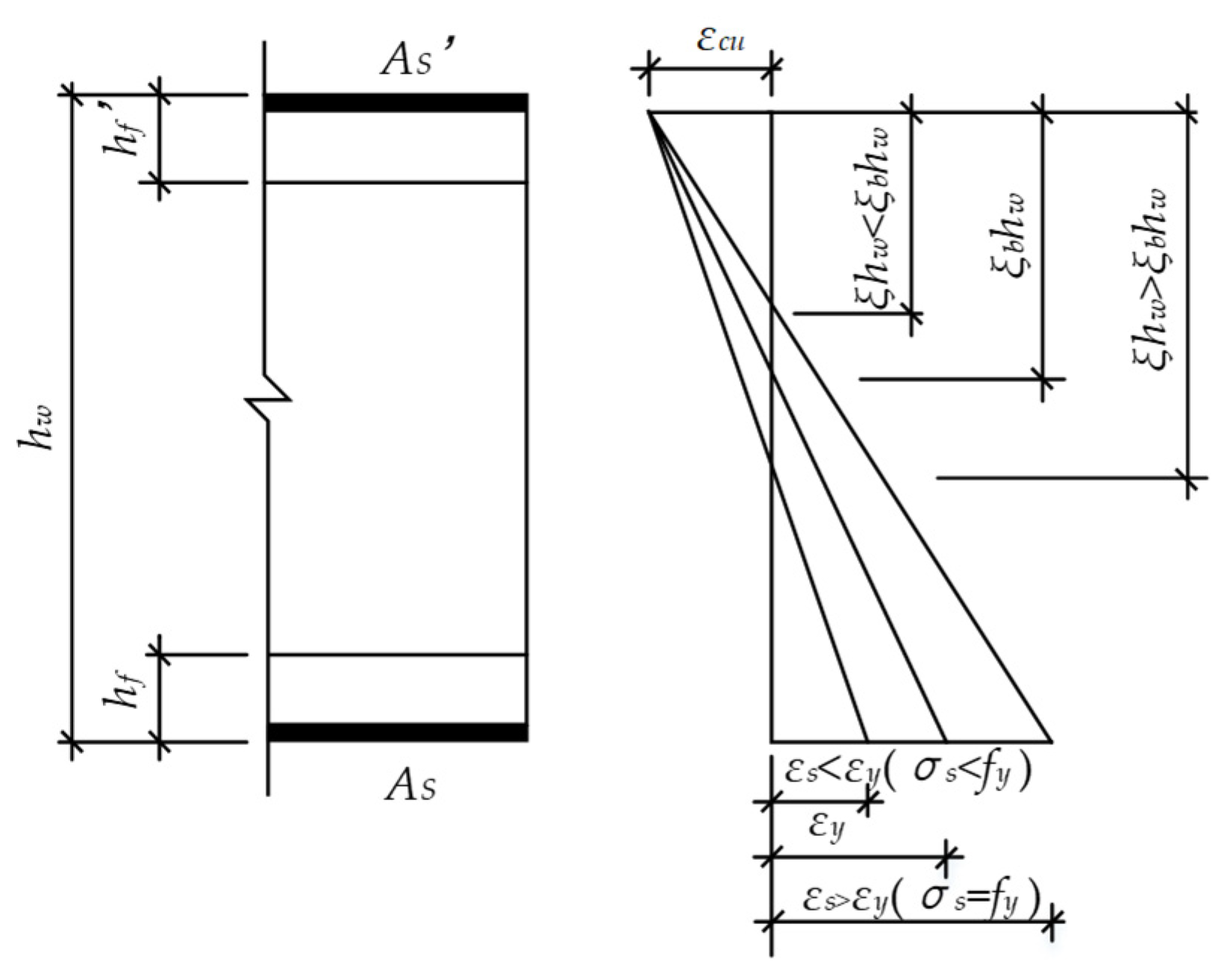
Figure 8.
Stress and strain distribution of cross section for the large eccentric SC wall. (a) Strain distribution of the cross section; (b) Stress distribution of the cross section.
Figure 8.
Stress and strain distribution of cross section for the large eccentric SC wall. (a) Strain distribution of the cross section; (b) Stress distribution of the cross section.

Figure 9.
Equivalence of web steel plate for the large eccentric SC wall. (a) Full plastic stress distribution; (b)Triangle stress distribution.
Figure 9.
Equivalence of web steel plate for the large eccentric SC wall. (a) Full plastic stress distribution; (b)Triangle stress distribution.
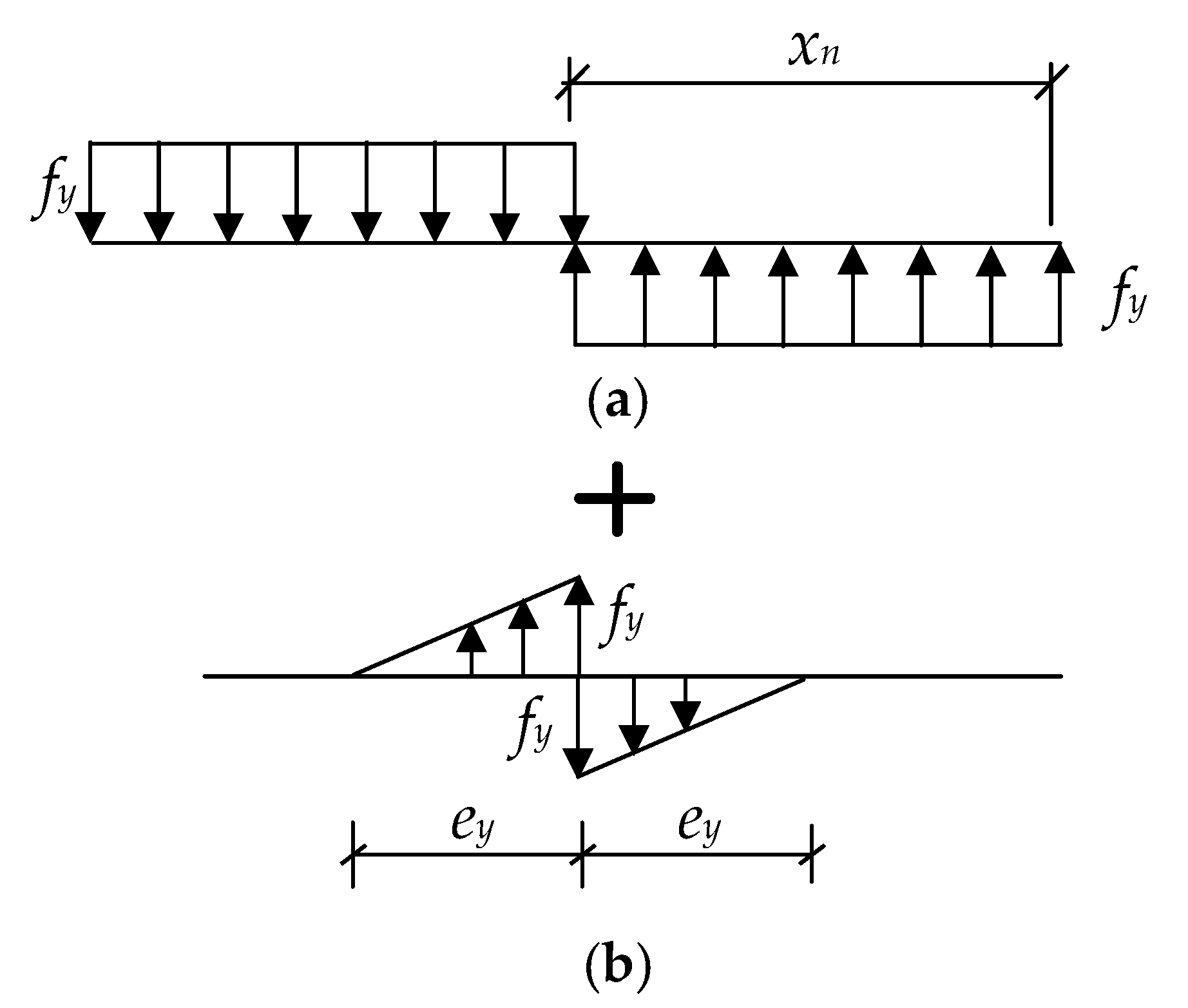
Figure 10.
Stress and strain distribution of cross section for the small eccentric SC wall. (a) Strain distribution of cross section; (b) Stress distribution of cross section.
Figure 10.
Stress and strain distribution of cross section for the small eccentric SC wall. (a) Strain distribution of cross section; (b) Stress distribution of cross section.
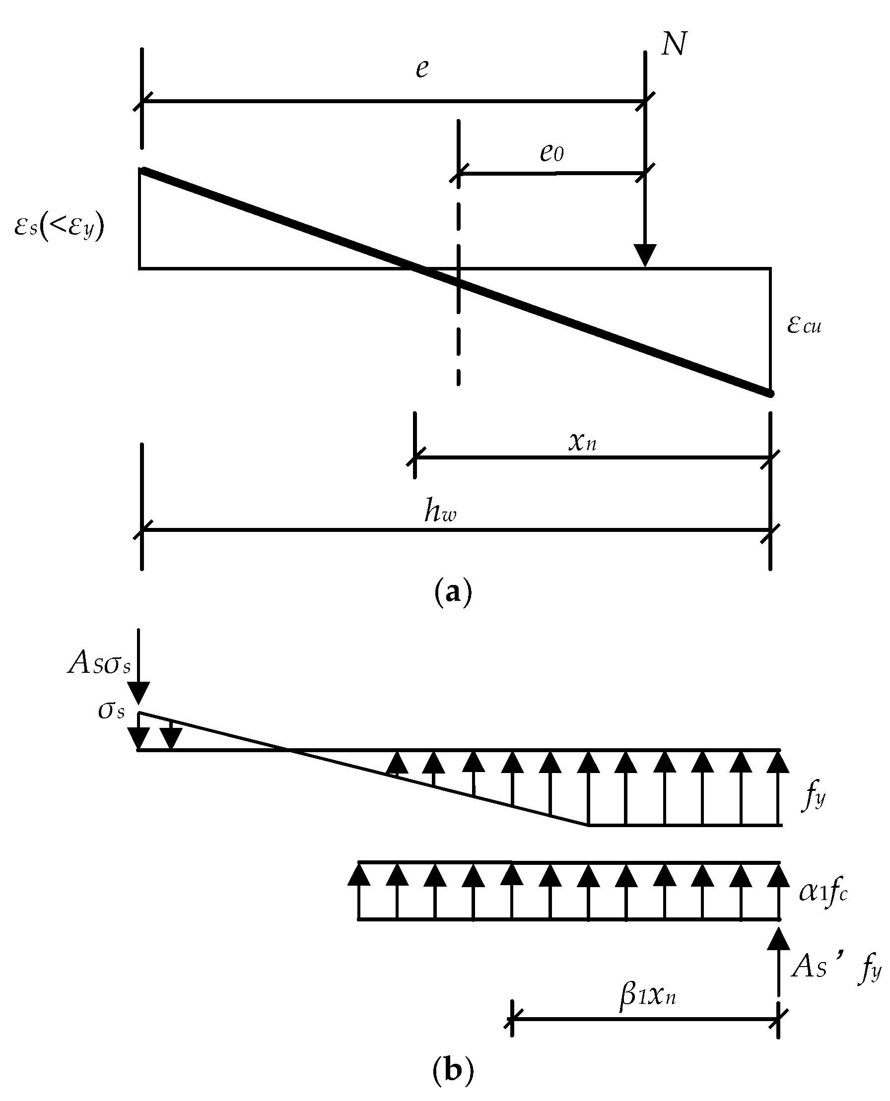
Figure 11.
Equivalence of web plate for the small eccentric SC wall.

Figure 12.
Comparison between test results and calculated results of specimens in the existing literature.
Figure 12.
Comparison between test results and calculated results of specimens in the existing literature.


Table 1.
The influence of B/t on local buckling of steel plates.
| Reference | Specimen | Pcr1/Pu2 | Buckling Pattern | B/t5 | The Limit of B/t |
|---|---|---|---|---|---|
| [9] | W0 | 0.63 | buckling1 3 | 58.8 | 34 |
| [10] | SCW5 | 0.91 | buckling2 | 40 | 34 |
| [12] | SCW1-1a | 0.95 | buckling2 4 | 13.3 | 33 |
| SCW1-1b | 0.96 | buckling2 | 13.3 | 33 | |
| SCW1-2a | 0.98 | buckling2 | 13.3 | 33 | |
| SCW1-2b | 1.00 | buckling2 | 13.3 | 33 | |
| SCW1-3 | 0.91 | buckling2 | 13.3 | 33 | |
| SCW1-4 | 0.94 | buckling2 | 20 | 34 | |
| SCW1-5 | 0.92 | buckling2 | 10 | 32 | |
| SCW1-6 | 0.90 | buckling2 | 26.7 | 33 |
1Pcr is the local buckling load of the column steel plate; 2 Pu is the ultimate load; 3 buckling1 means the concrete at the embedded column is not crushed when the steel plate buckling occurs; 4 buckling2 means the steel plate buckling occurs accompanied with the concrete crushed and pushed out; 5 B/t is calculated by
referring to [22].
Table 2.
The parameters of specimens.
| Specimen | Specimen Size | Steel Plane Thickness | Design Axial Compression Ratio | Stud Spacing | ||
|---|---|---|---|---|---|---|
| Height | Width | Thickness | ||||
| SCW1-1a | 1000 | 1000 | 150 | 3 | 0.4 | 40 |
| SCW1-1b | 1000 | 1000 | 150 | 3 | 0.4 | 40 |
| SCW1-2a | 1500 | 1000 | 150 | 3 | 0.4 | 40 |
| SCW1-2b | 1500 | 1000 | 150 | 3 | 0.4 | 40 |
| SCW1-3 | 2000 | 1000 | 150 | 3 | 0.4 | 40 |
| SCW1-4 | 1000 | 1000 | 150 | 2 | 0.4 | 40 |
| SCW1-5 | 1000 | 1000 | 150 | 4 | 0.4 | 40 |
| SCW1-6 | 1000 | 1000 | 150 | 3 | 0.4 | 80 |
© 2020 by the authors. Licensee MDPI, Basel, Switzerland. This article is an open access article distributed under the terms and conditions of the Creative Commons Attribution (CC BY) license (http://creativecommons.org/licenses/by/4.0/).
Share and Cite
MDPI and ACS Style
Zhang, P.; Guo, Q.; Ke, F.; Zhao, W.; Ye, Y. Axial and Bending Bearing Capacity of Double-Steel-Concrete Composite Shear Walls. Appl. Sci. 2020, 10, 4935. https://doi.org/10.3390/app10144935
AMA Style
Zhang P, Guo Q, Ke F, Zhao W, Ye Y. Axial and Bending Bearing Capacity of Double-Steel-Concrete Composite Shear Walls. Applied Sciences. 2020; 10(14):4935. https://doi.org/10.3390/app10144935
Chicago/Turabian StyleZhang, Peiyao, Quanquan Guo, Fei Ke, Weiyi Zhao, and Yinghua Ye. 2020. "Axial and Bending Bearing Capacity of Double-Steel-Concrete Composite Shear Walls" Applied Sciences 10, no. 14: 4935. https://doi.org/10.3390/app10144935
Note that from the first issue of 2016, this journal uses article numbers instead of page numbers. See further details here.