Experimental Investigation on the Mechanical Properties of Curved Metallic Plate Dampers


1
School of Science, Qingdao University of Technology, Qingdao 266033, China
2
School of Civil Engineering, Qingdao University of Technology, Qingdao 266033, China
3
Beijing Advanced Innovation Center for Future Urban Design, Beijing 100044, China
4
School of Civil and Transportation Engineering, Beijing University of Civil Engineering and Architecture, Beijing 100044, China
5
School of Civil Engineering, Southeast University, Nanjing 210096, China
*
Author to whom correspondence should be addressed.
Appl. Sci. 2020, 10(1), 269; https://doi.org/10.3390/app10010269
Submission received: 11 November 2019
/
Revised: 23 December 2019
/
Accepted: 24 December 2019
/
Published: 30 December 2019
(This article belongs to the Special Issue Recent Advances in the Design of Structures with Passive Energy Dissipation Systems)
Abstract
:This study proposes a novel curved steel plate damper to improve the seismic performance of structures. The theoretical analysis of the curved plate damper was carried out deriving formulas of key parameters of the curved plate damper including elastic lateral stiffness, yield strength, and yield displacement. Moreover, a cyclic loading test of four sets of specimens was conducted, and the hysteretic performance, ductility, energy dissipation performance, and strain of the specimens were studied. The results showed that the initial stiffness of the damper was large, no obvious damage was observed, and the hysteresis loop was full. The tested dampers had good deformation and energy dissipation performance. The stress variable rule of the damper was obtained by stress analysis, where the plastic deformation at the end of the semi-circular arc was large. The formula for various parameters of the damper was compared with experimental and numerical results; thus, the value of the adjustment coefficient was determined reasonable. Meanwhile, the rationality of the finite element model was also verified.
1. Introduction
Earthquakes are sudden natural disasters endangering people’s lives and property. The may not only cause housing damage, traffic interruption, water disaster, fire, disease, and other secondary disasters, but can also endanger human life and safety.
To minimize casualties and economic losses, preventing structural collapse and serious damage to the civil infrastructure against seismic hazard has become a challenging task that researchers need to address. Improving the seismic capacity of engineering structures through novel techniques and technical measures is the most effective way to mitigate seismic hazards. The traditional seismic method takes the “anti-seismic” approach as an important way to resist earthquakes by enlarging the section of structures and adding more reinforcements. The result is that the larger the section of structural components is, the greater the stiffness becomes, and the greater the impact of earthquakes. In this vicious circle, it is not only difficult to ensure safety, but construction costs required for earthquake resistance also increase greatly.
An effective way to overcome increased inertia properties is structural vibration control through energy dissipation devices. Energy dissipation devices absorb and dissipate seismic energy, thereby reducing the dynamic response of the main structure under an earthquake. Based on numerous practical applications of energy dissipation devices, the vibration control technique can be used to mitigate seismic hazard and achieve better seismic performance of the structure under vibrations.
The passive energy dissipation method has been widely used in the seismic control of structures since the 1980s [1,2]. Dampers can be classified into metal, viscoelastic [3], viscous [4], tuned absorption dampers [5], smart materials based isolation and suspension system [6,7], recently developed smart materials based damping or negative stiffness structure [8,9,10], actively tuned damper and driver system [11,12], according to the energy dissipation methods, control force characteristics [13] as well as materials used. The metal damper has a certain stiffness, and its energy dissipation mechanism depends on the elastic-plastic deformation. It is cheap, easy to install, and less affected by temperature. Therefore, it is suitable for all kinds of building structures and has a good economic value and effectiveness for the reinforcement and reconstruction of existing and new buildings. Metallic dampers can further be categorized into axial yield [14,15], shear yield [16], flexural yield [17,18], and combined yield devices [19].
Existing forms of flexural yield dampers include the added damping and stiffness (ADAS) device [20,21,22], triangular added damping and stiffness (TADAS) device [23,24], knee brace device [25,26], steel-composited wall dampers and B-C-W members [27,28], non-uniform steel strip damper [29], rhombic low yield strength steel plate [30], J-shaped steel hysteresis damper [31,32], U-shaped damper [33,34,35], pipe damper [36], dual-pipe damper [37], bar-fuse damper [38], accordion metallic damper [39], pipe-fuse damper [40], pure bending yielding dissipater [41], crawler steel damper [42], and hourglass-shaped strip damper [43].
Because the yield load of single-sheet steel is small, some bending plate dampers need to be combined with multiple sheets of the steel plate. In order to facilitate the energy consumption and reduce the stress concentration, it is necessary to optimize the shape of the steel plate, which makes the processing difficult and cannot eliminate the influence of the vertical force on the damper. In view of the above problems, this paper proposes the improvement of a curved plate damper based on the principle of the U-shaped damper. The mechanical characteristics and energy dissipation capacity of the curved plate damper were investigated using theoretical and experimental methods.
2. Performance Parameters of Curved Plate Damper
Three views with dimensioning is shown in Figure 1. The parameters of the curved plate damper mainly include thickness (t), width (b), and radius (R, R = R′ − t/2). The performance of the damper will vary with the parameters. The AB section and CD section of the damper are straight sections connected with other components, which constitutes the non-energy-consuming part of the damper, as shown in Figure 1a. The half-arc AC and BD segments are the main work parts of the damper.
2.1. Elastic Stiffness Calculation Formula
A single semi-circular arc steel plate was taken as the research object, which can be regarded as a curved beam with two fixed ends [44], as shown in Figure 2a. Figure 2b shows the deformation sketch and internal force analysis diagram of the central axis of the semi-circular arc steel plate when displacement (Δ = 1) occurs at the support.
According to the elastic center method, using the symmetry of the structure, M and Q are unknown symmetric forces, F is an unknown anti-symmetric force, and the force method equation can be simplified as follows:
Using the rigid arm, the sum of and equals zero. Therefore, the simplified form of the equation is expressed as follows:
where and are zero due to the horizontal displacement of the support. In addition, the bending moment (M) and vertical force (Q) at the elastic center are both zero. Thus, the above simplified equation can be written as follows:
where and can be written as
Introducing Equations (4) and (5) into (3), the force can be obtained as
where F is the force at the end of the damper with unit displacement, which is the elastic stiffness of the damper with a semi-curved steel plate, and G is the shear modulus of elasticity (G = 0.4E). The elastic stiffness of the damper can be simplified as follows:
where E is the elastic modulus of the material, b is the width of the curved plate damper, and t is the thickness of the curved plate damper.
2.2. Formula for Calculating Yield Strength
From the balance mechanism of the forces, the expression of elastic ultimate strength can be obtained as
The elastic ultimate strength can also be written as
where is the yield load, and is the elastic moment of resistance.
The method for determining the yield displacement in this paper is shown in Figure 3. The horizontal and vertical coordinates at the intersection of tangent OA and AB are the yield displacement and yield strength, respectively. Because the yield strength is greater than the elastic ultimate strength, the adjustment coefficient is introduced.
The adjustment coefficient of the yield load can be determined by relevant tests and numerical analysis. The yield load can be written as
2.3. Formula for Calculating Yield Displacement
The yield displacement can be expressed as
From Equations (7), (9), and (11), the elastic stiffness, yield strength, and yield displacement of curved plate dampers can be calculated. By adjusting the relevant parameters, a damper was designed to meet the needs of the project.
3. Mechanical Properties of Curved Plate Damper
The curved plate damper was made of Q235B steel. Four groups of specimens were designed for the material properties test. The thickness of steel plates for specimens 1 and 2 was 10 mm, and that for specimens 3 and 4 was 6 mm. The material property test was loaded with a servo actuator (maximum force capacity: 500 kN) in Civil Test Center of Southeast University (Nanjing, China) with a loading rate of 1.2 mm/min. Based on the analysis of stress and strain data, the yield point was taken as the yield strength of the steel. The mechanical properties of steel are shown in Table 1.
The four groups of curved plate dampers were named as CSPD-1, CSPD-2, CSPD-3, and CSPD-4, respectively. The length of the straight section of the four groups was the same. Their geometric dimensions are shown in Table 2.
3.1. Loading Device and Test Scheme
The test was carried out in Civil Test Center of Southeast University (Nanjing, China). The loading equipment was a MTS 50-ton fatigue testing machine. The experiment was divided into four groups with eight specimens, with each group having two identical specimens. In order to connect with the servo actuator, a fixture was designed as shown in Figure 4. The inverted T-splint and T-base are equipped with triangular stiffening ribs, and the components of the fixture are connected by the bolts.
The test was divided into standard loading and fatigue loading. According to the multiple of the yield displacement of the damper (△), the target displacements of the CSPD-1 specimens were 2 mm (0.5 △), 4 mm (1 △), 8 mm (2 △), 12 mm (3 △), 16 mm (4 △), 20 mm (5 △), 24 mm (6 △), 28 mm (7 △), 32 mm (8 △), 36 mm (9 △), and 40 mm (10 △), respectively. According to the multiple of yield displacement, all specimens in this test were loaded in 11 stages. The target displacements of CSPD-2 were 1.2, 2.4, 4.8, 7.2, 9.6, 12, 14.4, 16.8, 19.2, 21.6, and 24 mm, respectively. The target displacements of CSPD-3 were 0.9, 1.8, 3.6, 5.4, 7.2, 9, 10.8, 12.6, 14.4, 16.2, and 18 mm, respectively. The target displacements of CSPD-4 were 2.1, 4.2, 8.4, 12.6, 16.8, 21, 25.2, 29.4, 33.6, 37.8, and 42 mm, and the target displacement circulated three times. For fatigue loading, the Code for Seismic Design of Buildings (GB 50011-2010) stipulates that the energy dissipator should circulate 30 times [13] under the designed displacement, and there should be no obvious low-cycle fatigue phenomenon. The fatigue loading displacements of CSPD-1, CSPD-2, CSPD-3, and CSPD-4 were 40, 24, 18, and 42 mm, respectively.
During the test, force and displacement data were automatically recorded by the servo actuator. In order to study the mechanical properties of the damper, strain gauges were attached to the damper. The locations of the measuring points are shown in Figure 5. Two strain gauges were attached to each group of specimens at positions 1, 2, and 3.
3.2. Experiment Result Analysis
The described four groups of specimens underwent standard loading. It was observed that when the displacement was small, the damper showed no obvious change. However, with the increase in displacement, the steel oxide layer of the damper’s semi-circular arc energy dissipation section appeared to warp and spall with a relatively higher spall at the end of the semi-circular arc. The damper produced plastic deformation during the cyclic loading process. The damper’s deformation when it was loaded to the maximum displacement is shown in Figure 6. After 30 cycles of fatigue loading, the damper had obvious deformations but no cracks. No obvious damage was observed and the damper had good integrity.
3.2.1. Hysteretic Curve
From the data collected by MTS equipment, the hysteretic curves of curved steel plate dampers are plotted in Figure 7. It can be seen that the hysteretic curves of dampers are full, the elastic stiffness is large, the stiffness of dampers after yielding decreases, and the maximum and minimum loads of dampers are not exactly the same. The reason may be that there were errors in the installation. The four groups of specimens circulated three times at each target displacement, and the three curves basically coincide, which indicates the stability of the damper.
Hysteretic curves under fatigue loading are shown in Figure 8. After 30 cycles of the cyclic loading, the load indices of the specimens CSPD-1 and CSPD-4 decreased, but the attenuation was far less than 15%. However, the load attenuation of the specimens CSPD-2 was higher, about 13.51%. The load attenuation of the specimens CSPD-3 presented positive and negative asymmetric state, which may be due to an installation error. Therefore, the performance of CSPD-2 was slightly worse than that of the other three specimens, but still met the relevant requirements of the code for dampers. It can be concluded that overall, the curved plate damper had good hysteretic performance.
3.2.2. Ductility Coefficient and Energy Dissipation Coefficient
According to the relevant provisions of test data processing in the code for seismic test methods of buildings (JGJ-96), the ductility coefficient is the ratio of ultimate displacement to yield displacement. The energy dissipation coefficient is measured by the envelope area of the hysteresis curve. The diagram of the hysteresis curve is shown in Figure 9. The ductility coefficient can be written as
The ductility coefficient and energy dissipation coefficient of the curved plate damper are shown in Table 3. The ductility and energy dissipation capacity of the four groups of specimens were good with few exceptions. Among them, CSPD-2 had the smallest ductility coefficient, and CSPD-3 had the smallest energy dissipation coefficient.
3.2.3. Strain Analysis
The longitudinal coordinate of the strain analysis curve represents the strain value at the measuring point. As shown in Figure 5, strain gauges were attached at three locations on the curved surface steel plate damper. Because the locations of measuring points 1 and 3 were the same, the average values of positive strain extremum at measuring points 1 and 3 were taken. The transverse coordinates were unified as the loading displacement (n × Δ), where Δ is the prediction of the yield displacement.
From Figure 10, it can be seen that the strain at point 1 is much larger than that at point 2, which shows that the plastic deformation at the end of the semi-circular arc was large, and that the stress was also large for curved plate dampers. It is not difficult to see from Figure 10a that when the loading displacement was greater than 3Δ, the strain values of the specimens began to differ significantly. The strains of specimens CSPD-1 and CSPD-4 increased rapidly. At 6Δ, the strain increment of the CSPD-2 specimens slowed down, while the strain of the CSPD-3 specimens increased rapidly from 7Δ.
Figure 10b demonstrates the strain curve at point 2. It can be seen that the strain increment trend of the four groups of specimens was approximately the same. When loaded to 10Δ, the strain values of the other specimens were similar except for the small strain values of CSPD-2 specimens.
3.3. Finite Element Analysis
3.3.1. Hysteresis Curve Analysis
The model shown in Figure 11 was built in general FEM software known as ANSYS. The shell unit shell181 was selected for the model. The constitutive relation of the bilinear follow-up reinforcement model was used for steel material. The elastic modulus of Q235 steel was used as 2.06 × 10⁵ Mpa, Poisson’s ratio as 0.3, and yield strength was taken according to Table 1. The model was developed according to the size of CSPD-1, CSPD-2, CSPD-3, and CSPD-4 dampers. The flat section of the bottom of the damper was completely fixed, while the flat section of the top was only horizontally displaced.
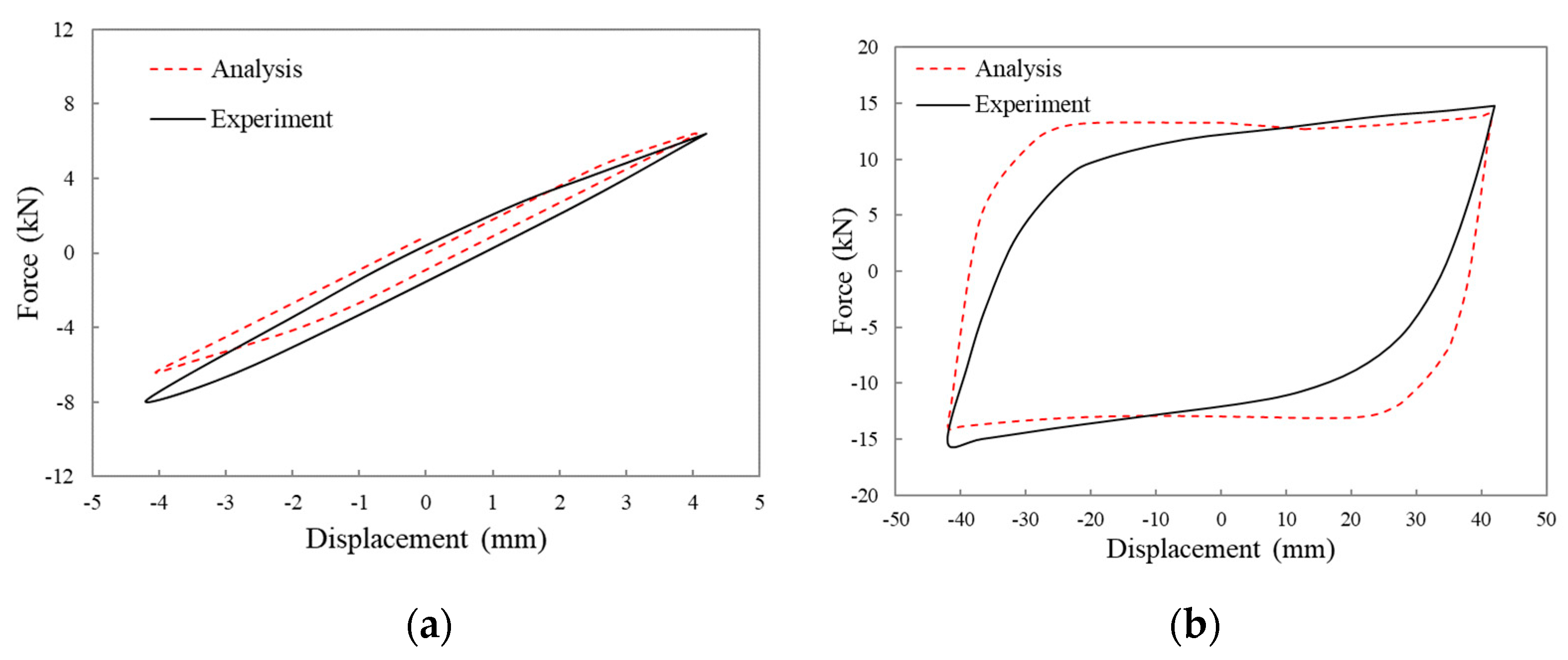
In the process of standard loading, the hysteretic loops of the double yield displacement and 10 yield displacements were compared with the results of the finite element method. Two specimens were used in each group at the same time. Therefore, the results of the finite element simulation needed to be magnified twice. Figure 12, Figure 13, Figure 14 and Figure 15 show the hysteretic curves of the four specimens.
- (1)
- In Figure 12, the hysteretic curve coincides well at 4 mm. The positive and negative values are asymmetric in the hysteretic curve at 40 mm. Because the stiffness of CSPD-1 is small, then the horizontal deformation causes an error in the final load value, when the load displacement is large.
- (2)
- In Figure 13, the asymmetry of the hysteretic curve also exists at 2.4 mm. At 24 mm, the maximum load of the test curve and the finite element curve are basically the same, but the envelope area of the finite element curve is slightly larger, and the second stiffness of the damper is smaller.
- (3)
- In Figure 14, the hysteretic curve coincides well at 1.8 mm. The maximum load coincides well at 24 mm, and the envelope area of the finite element curve is slightly larger.
- (4)
- In Figure 15, the hysteretic curve coincides well at 4.2 mm, and the curve of finite element analysis shows an upward trend at 42 mm, which is different from the shape of the test curve. This is because the boundary condition set in the finite element analysis is complete bonding, and a bolt connection is used in the test, which cannot be precisely achieved.
Generally speaking, the curve of the finite element analysis is basically the same as that of the test; therefore, the finite element model is reasonable. However, the ideal elastic-plastic model of material in the finite element is different from the actual material. There are many factors affecting the test process, including processing, installation, and other errors. It is impossible to achieve the ideal state in finite element settings, and some errors are acceptable.
3.3.2. Analysis of Mechanical Property Parameters
According to the theoretical formula of the curved plate damper, combined with the experimental and numerical data presented in this paper, a comparison of mechanical properties of curved plate dampers is provided in Table 4. The coefficient beta (β)in the calculation formula can be determined according to the test value and the finite element value. The yield displacement and yield bearing capacity in the test and the finite element simulation were averaged, and then, correspondingly, the theoretical values were determined to be equal. The error was smaller when the calculation yields a β factor value of 1.78. The maximum error of the mechanical properties is listed in Table 4. Except for some errors of elastic stiffness greater than 10%, the other errors were smaller. This shows that the finite element calculations in conjunction with theoretical formulae can reasonably reflect the performance of the damper.
4. Conclusions
In this paper, four groups of curved plate dampers were selected for theoretical analysis and mechanical properties testing. The main conclusions are as follows:
- (1)
- No visible cracks were found in the dampers during standard loading and fatigue loading, and no obvious damage was observed. The hysteretic curves of standard loading and fatigue loading were very full. In standard loading, each target displacement cycle had three cycles, and the three curves coincided. After 30 cycles of the fatigue cycle, the attenuation of the load index was less than 15%, which indicates that the damper had stable performance. It can be seen from the ductility and energy dissipation coefficient that the four dampers have good deformation and energy dissipation performance.
- (2)
- Through stress analysis, the strain at the top of the semi-circular arc was much smaller than that of the end of the semi-circular arc, which shows that for curved plate dampers, the plastic deformation at the end of the semi-circular arc was large, the stress was also large, and the strain change rate was also large.
- (3)
- The finite element model was established to simulate the loading process of the specimens. Compared with the hysteretic curves obtained in the test, it was found that the two curves were basically the same except for the individual specimens. Because there are many influencing factors in the testing process, the positive and negative hysteretic asymmetry of the test curve will occur when the small displacement is loaded. In case of the large displacement, the hysteretic area of the finite element analysis curve is slightly larger. The mechanical properties of the damper can be obtained through experiments, finite element simulations, and theoretical calculations. It is reasonable to obtain a coefficient beta of 1.78 by numerical and theoretical computations. The maximum error was within the allowable range. At the same time, the correctness of the finite element model and the theoretical formulae was proved.
In conclusion, the curved plate damper had the characteristics of a simple structure, clear mechanical performance, and good stability.
Author Contributions
Conceptualization, J.Z., A.L. and C.Z.; methodology, J.Z.; software, J.Z.; formal analysis, J.Z.; writing—original draft preparation, J.Z.; Writing—review and editing, C.Z. All authors have read and agreed to the published version of the manuscript.
Funding
The research was financially supported by the Ministry of Science and Technology of China (Grant No. 2017YFC0703603), the National Natural Science Foundation of China (Grant No. 51678322), the Qingdao postdoctoral application research project (Grant No. 2018152), the Taishan Scholar Priority Discipline Talent Group program funded by the Shandong Province, the Cooperative Innovation Center of Engineering Construction and Safety in Shandong Blue Economic Zone, and the first-class discipline project funded by the Education Department of Shandong Province.
Conflicts of Interest
The authors declare no conflicts of interest.
References
- Housner, G.W.; Bergman, L.A.; Caughey, T.K.; Chassiakos, A.G.; Claus, R.O.; Masri, S.F.; Skelton, R.E.; Soong, T.T.; Spencer, B.F.; Yao, J.T. Structural control: Past, present, and future. ASCE J. Eng. Mech. 1997, 123, 897–971. [Google Scholar] [CrossRef]
- Soong, T.T.; Dargush, G.F. Passive Energy Dissipation Systems in Structural Engineering; Wiley: London, UK, 1997. [Google Scholar]
- Mahmoodi, P.; Keel, C.J. Performance of viscoelastic structural dampers for the Columbia center building. In Building Motion in Wind; ASCE: New York, NY, USA, 1986; pp. 83–106. [Google Scholar]
- De Domenico, D.; Ricciardi, G.; Takewaki, I. Design strategies of viscous dampers for seismic protection of building structures: A review. Soil Dyn. Earthq. Eng. 2019, 118, 144–165. [Google Scholar] [CrossRef]
- Zhang, C.W.; Li, L.Y.; Ou, J.P. Swinging motion control of suspended structures: Principles and applications. Struct. Control Health Monit. 2010, 17, 549–562. [Google Scholar] [CrossRef]
- Fu, W.Q.; Zhang, C.W.; Sun, L.; Askari, M.; Samali, B.; Chung, K.L.; Sharafi, P. Experimental investigation of a base isolation system incorporating mr dampers with the high-order single step control algorithm. Appl. Sci. 2017, 7, 344. [Google Scholar] [CrossRef] [Green Version]
- Zhang, C.W.; Ou, J.P.; Zhang, J.Q. Parameter optimization and analysis of a vehicle suspension system controlled by magnetorheological fluid dampers. Struct. Control Health Monit. 2006, 13, 885–896. [Google Scholar] [CrossRef]
- Wei, M.; Sun, L.; Hu, G. Dynamic properties of an axially moving sandwich beam with magnetorheological fluid core. Adv. Mech. Eng. 2017, 9. [Google Scholar] [CrossRef] [Green Version]
- Sun, L.; Huang, W.M. Wet to shrink: An approach to realize negative expansion upon wetting. Adv. Compos. Mater. 2009, 18, 95–103. [Google Scholar] [CrossRef]
- Wei, M.H.; Sun, L.; Zhang, C.; Qi, P.P.; Zhu, J. Shear-thickening performance of suspensions of mixed ceria and silica nanoparticles. J. Mater. Sci. 2019, 54, 346–355. [Google Scholar] [CrossRef]
- Zhang, C.W.; Ou, J.P. Modeling and Dynamical Performance of the Electromagnetic Mass Driver System for Structural Vibration Control. Eng. Struct. 2015, 82, 93–103. [Google Scholar] [CrossRef]
- Zhang, C.W.; Ou, J.P. Control Structure Interaction of Electromagnetic Mass Damper System for Structural Vibration Control. ASCE J. Eng. Mech. 2008, 134, 428–437. [Google Scholar] [CrossRef]
- Zhang, C.W. Control Force Characteristics of Different Control Strategies for the Wind-excited 76-story Benchmark Building Structure. Adv. Struct. Eng. 2014, 17, 543–559. [Google Scholar] [CrossRef]
- Ju, Y.K.; Kim, M.H.; Kim, J.; Kim, S.D. Component tests of buckling-restrained braces with unconstrained length. Eng. Struct. 2009, 31, 507–516. [Google Scholar] [CrossRef]
- Xie, Q. State of the art of buckling-restrained braces in Asia. J. Constr. Steel Res. 2005, 61, 727–748. [Google Scholar] [CrossRef]
- Chen, S.J.; Jhang, C. Experimental study of low-yield-point steel plate shear wall under in-plane load. J. Constr. Steel Res. 2011, 67, 977–985. [Google Scholar] [CrossRef]
- Whittaker, A.S.; Bertero, V.V.; Thompson, C.L.; Alonso, L.J. Seismic testing of steel plate energy dissipation devices. Earthq. Spectra 1991, 7, 563–604. [Google Scholar] [CrossRef]
- Chan, R.W.K.; Albermani, F. Experimental study of steel slit damper for passive energy dissipation. Eng. Struct. 2008, 30, 1058–1166. [Google Scholar] [CrossRef]
- Li, H.N.; Li, G. Experimental study of structure with “dual function” metallic dampers. Eng. Struct. 2007, 29, 1917–1928. [Google Scholar] [CrossRef]
- Whittaker, A.; Bertero, V.; Alonso, J.; Thompson, C. Earthquake Simulator Testing of Steel Plate Added Damping and Stiffness Elements; Report No. UCB/EERC-89/02; Earthquake Engineering Research Center, University of California: Berkeley, CA, USA, 1989. [Google Scholar]
- Symans, M.D.; Charney, F.A.; Whittaker, A.S.; Constantinou, M.C.; Kircher, C.A.; Johnson, M.W.; McNamara, R.J. Energy dissipation systems for seismic applications: Current practice and recent developments. J. Struct. Eng. 2008, 134, 3–21. [Google Scholar] [CrossRef] [Green Version]
- Bedon, C.; Amadio, C. Passive control systems for the blast enhancement of glazing curtain walls under explosive loads. Open Civ. Eng. 2017, 11, 396–419. [Google Scholar] [CrossRef] [Green Version]
- Tsai, K.C.; Chen, H.W.; Hong, C.P.; Su, Y.F. Design of steel triangular plate energy absorbers for seismic-resistant construction. Earthq. Spectra 1993, 9, 505–528. [Google Scholar] [CrossRef]
- Gray, M.; Christopoulos, C.; Packer, J.; de Oliveira, C. A new brace option for ductile braced frames. Mod. Steel Constr. 2012, 52, 40–53. [Google Scholar]
- Balendra, T.; Lim, E.L.; Liaw, C.Y. Large scale seismic testing of knee brace frame. J. Struct. Eng. 1997, 123, 11–19. [Google Scholar] [CrossRef]
- Mahmoudi, M.; Montazeri, S.; Abad, M.J.S. Seismic performance of steel X-knee-braced frames equipped with shape memory alloy bars. J. Constr. Steel Res. 2018, 147, 171–186. [Google Scholar] [CrossRef]
- Zhang, C.W.; An, D.; Zhu, L. Axial Compressive Behavior Behavior of Steel-Damping Concrete Composite Wall. Appl. Sci. 2019, 9, 4679. [Google Scholar] [CrossRef] [Green Version]
- Zhu, L.M.; Zhang, C.W.; Guan, X.M.; Uy, B.; Sun, L.; Wang, B.L. The multi-axial strength performance of composite structural B-C-W members subjected to shear forces. Steel Compos. Struct. 2018, 27, 75–87. [Google Scholar]
- Lee, C.H.; Ju, Y.K.; Min, J.K.; Lho, S.H.; Kim, S.D. Non-uniform steel strip dampers subjected to cyclic loadings. Eng. Struct. 2015, 99, 192–204. [Google Scholar] [CrossRef]
- Shih, M.H.; Sung, W.P. A model for hysteretic behavior of rhombic low yield strength steel added damping and stiffness. Comput. Struct. 2005, 83, 895–908. [Google Scholar] [CrossRef]
- Kato, S.; Kim, Y.B.; Nakazawa, S.; Ohya, T. Simulation of the cyclic behavior of J-shaped steel hysteresis devices and study on the efficiency for reducing earthquake responses of space structures. J. Constr. Steel Res. 2005, 61, 1457–1473. [Google Scholar] [CrossRef]
- Kato, S.; Kim, Y.B. A finite element parametric study on the mechanical properties of J-shaped steel hysteresis devices. J. Constr. Steel Res. 2006, 62, 802–811. [Google Scholar] [CrossRef]
- Deng, K.; Pan, P.; Su, Y.; Xue, Y. Shape optimization of U-shaped damper for improving its bi-directional performance under cyclic loading. Eng. Struct. 2015, 93, 27–45. [Google Scholar] [CrossRef]
- Aguirre, M.; Sanchez, A.R. Structural seismic damper. J. Struct. Eng. 1992, 118, 1158–1171. [Google Scholar] [CrossRef]
- Tagawa, H.; Gao, J. Evaluation of vibration control system with U-dampers based on quasi-linear motion mechanism. J. Constr. Steel Res. 2012, 70, 213–225. [Google Scholar] [CrossRef]
- Maleki, S.; Bagheri, S. Pipe damper, part I: Experimental and analytical study. J. Constr. Steel Res. 2010, 66, 1088–1095. [Google Scholar] [CrossRef]
- Maleki, S.; Mahjoubi, S. Dual-pipe damper. J. Constr. Steel Res. 2013, 85, 81–91. [Google Scholar] [CrossRef]
- Aghlara, R.; Tahir, M.M. A passive metallic damper with replaceable steel bar compo-nents for earthquake protection of structures. Eng. Struct. 2018, 159, 185–197. [Google Scholar] [CrossRef]
- Motamedi, M.; Nateghi, F. Study on mechanical characteristics of accordion metallic damper. J. Constr. Steel Res. 2018, 142, 68–77. [Google Scholar] [CrossRef]
- Aghlara, R.; Tahir, M.M.; Adnan, A.B. Experimental study of pipe-fuse damper for passive energy dissipation in structures. J. Constr. Steel Res. 2018, 148, 351–360. [Google Scholar] [CrossRef]
- Zibasokhan, H.; Behnamfar, F.; Azhari, M. Experimental study of a new pure bending yielding dissipater. Bull. Earthq. Eng. 2019, 17, 4389–4410. [Google Scholar] [CrossRef]
- Deng, K.; Pan, P.; Wang, C. Development of crawler steel damper for bridges. J. Constr. Steel Res. 2013, 85, 140–150. [Google Scholar] [CrossRef]
- Lee, C.H.; Lho, S.H.; Kim, D.H.; Oh, J.; Ju, Y.K. Hourglass-shaped strip damper subjected to monotonic and cyclic loadings. Eng. Struct. 2016, 119, 122–134. [Google Scholar] [CrossRef]
- Long, Y.; Bao, S. Structural Mechanics; Higher Education Press: Beijing, China, 1994. [Google Scholar]
Figure 1.
Front (a), lateral (b), and vertical (c) views of the curved plate damper.

Figure 2.
Diagram of a single semi-circular arc steel plate (a) and computing model (b).

Figure 3.
Schematic diagram of yield displacement.

Figure 4.
Schematic diagram of the fixture (a) and photograph (b) of the testing device.
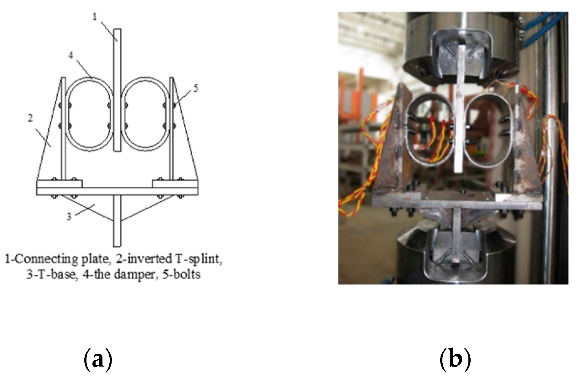
Figure 5.
Gauge position.
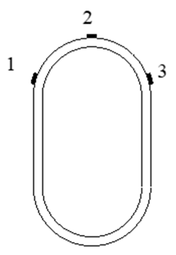
Figure 6.
Deformation of CSPD-1 (a), CSPD-2 (b), CSPD-3 (c), and COPD-4 (d) specimens at maximum displacement.
Figure 6.
Deformation of CSPD-1 (a), CSPD-2 (b), CSPD-3 (c), and COPD-4 (d) specimens at maximum displacement.
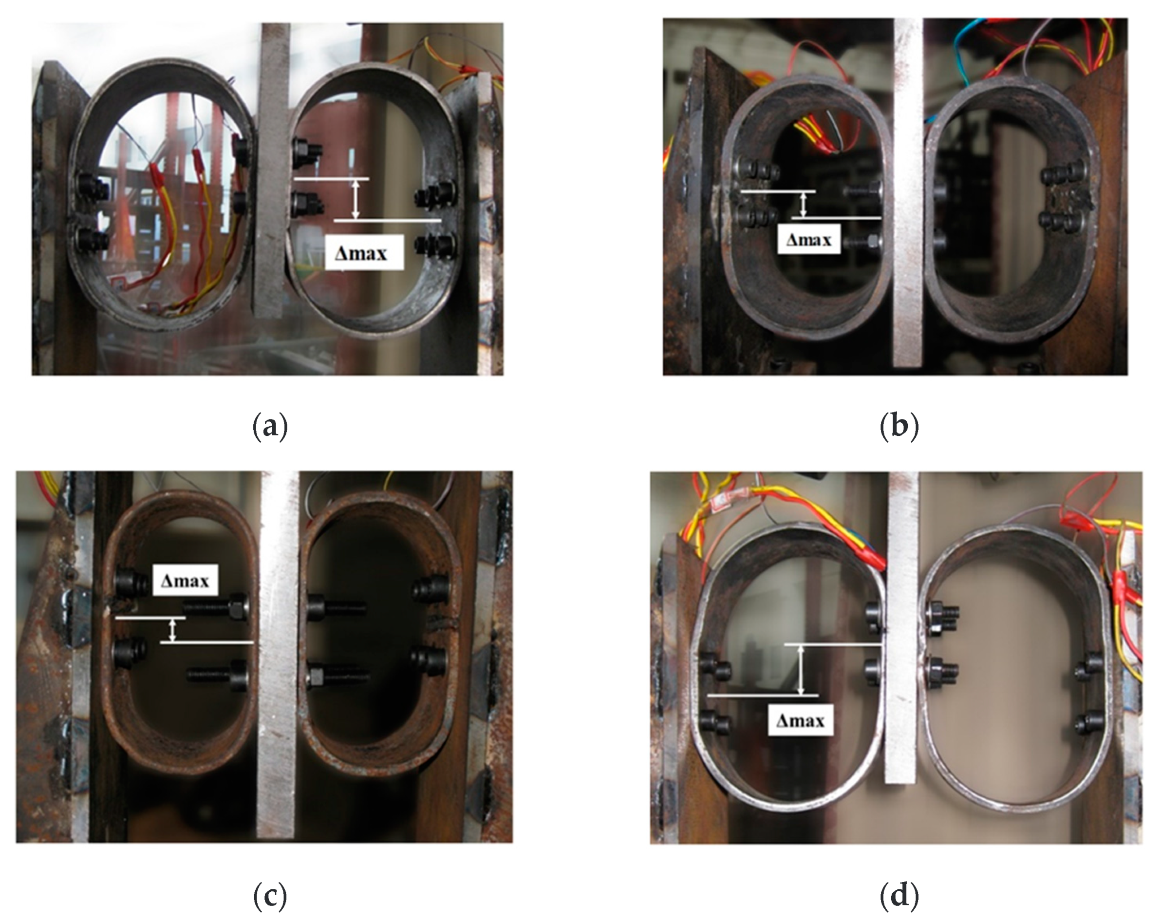
Figure 7.
Hysteretic curves of CSPD-1 (a), CSPD-2 (b), CSPD-3 (c), andCSPD-4 (d) under standard loading.
Figure 7.
Hysteretic curves of CSPD-1 (a), CSPD-2 (b), CSPD-3 (c), andCSPD-4 (d) under standard loading.
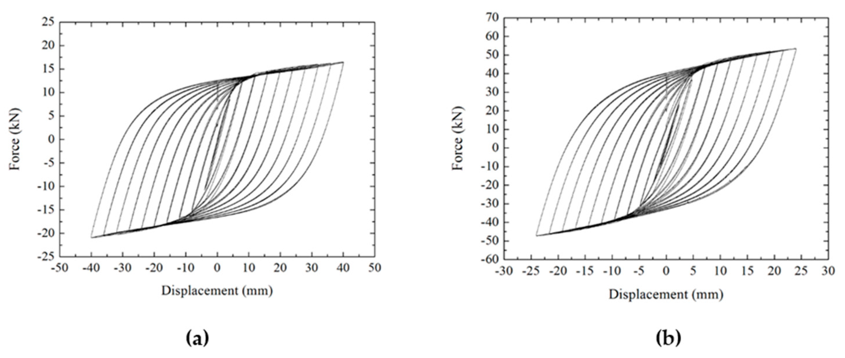
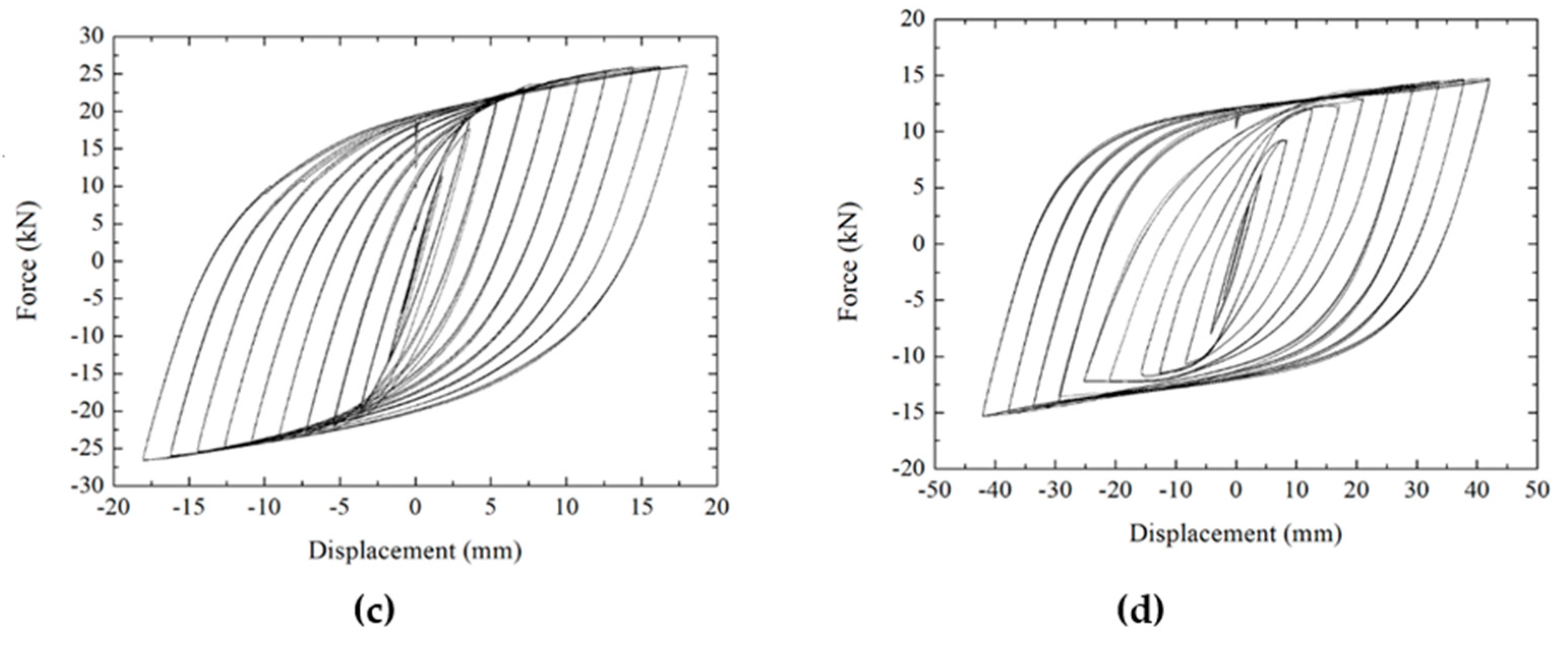
Figure 8.
Hysteretic curve of CSPD-1 (a), CSPD-2 (b), CSPD-3 (c), and CSPD-4 (d) under fatigue loading.
Figure 8.
Hysteretic curve of CSPD-1 (a), CSPD-2 (b), CSPD-3 (c), and CSPD-4 (d) under fatigue loading.

Figure 9.
Diagram of the hysteresis curve.
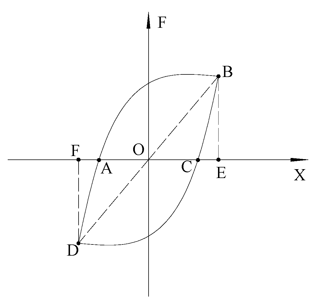
Figure 10.
Strain at points 1 (a) and 2 (b).

Figure 11.
Finite element model.
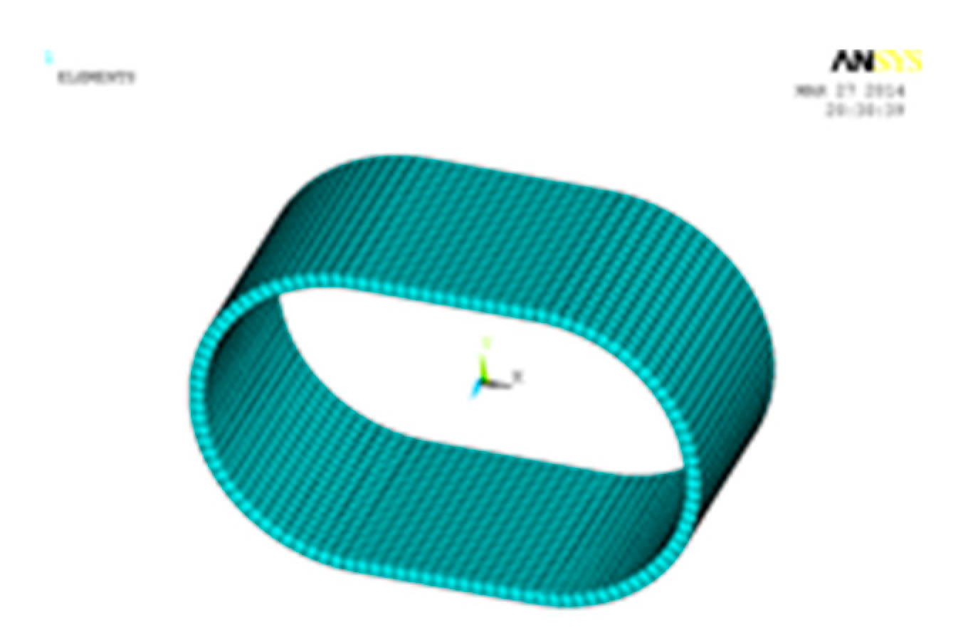
Figure 12.
Hysteresis curve at 4 mm (a) and 40 mm (b) of CSPD-1.
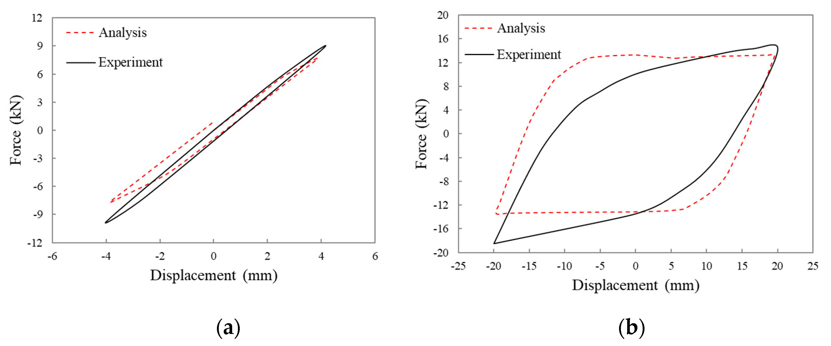
Figure 13.
Hysteresis curve at 2.4 mm (a) and 24 mm (b) of CSPD-2.

Figure 14.
Hysteresis curve at 1.8 mm (a) and 18 mm (b) of CSPD-3.

Figure 15.
Hysteresis curve at 4.2 mm (a) and 42 mm (b) of CSPD-4.

Table 1.
Mechanical properties of steel.
| Specimen | Yield Strength/MPa | Tensile Strength/MPa | Yield Ratio/% | Elongation/% |
|---|---|---|---|---|
| CSPD (curved steel plate dampers)-1 | 249.48 | 375.47 | 66.44 | 35.20 |
| CSPD-2 | 236.64 | 370.03 | 63.95 | 37.71 |
| CSPD-3 | 245.09 | 358.03 | 68.46 | 37.59 |
| CSPD-4 | 253.86 | 372.93 | 68.07 | 33.44 |
Table 2.
Specimen sizes.
| Specimen | b/mm | t/mm | R′/mm | Straight Section/mm |
|---|---|---|---|---|
| CSPD-1 | 105 | 6 | 65 | 70 |
| CSPD-2 | 105 | 10 | 65 | 70 |
| CSPD-3 | 105 | 6 | 43 | 70 |
| CSPD-4 | 85 | 6 | 65 | 70 |
Table 3.
Mechanical properties of curved plate damper.
| Specimen | Yield Displacement/mm | Limit Displacement/mm | Ductility Coefficient μ | Energy Dissipation Coefficient E |
|---|---|---|---|---|
| CSPD-1 | 4.37 | 40 | 9.15 | 2.90 |
| CSPD-2 | 2.66 | 24 | 9.02 | 2.83 |
| CSPD-3 | 1.86 | 18 | 9.68 | 2.73 |
| CSPD-4 | 4.52 | 42 | 9.29 | 2.96 |
Table 4.
Comparison of mechanical properties of curved plate dampers.
| Items | CSPD-1 | CSPD-3 | CSPD-4 | CSPD-6 | |
|---|---|---|---|---|---|
| Test result | Yield displacement (mm) | 4.37 | 2.66 | 1.86 | 4.52 |
| Yield bearing capacity (kN) | 8.78 | 25.42 | 12.53 | 6.97 | |
| Elastic stiffness (kN/mm) | 1.92 | 9.56 | 6.74 | 1.54 | |
| Finite element simulation | Yield displacement (mm) | 4.18 | 2.44 | 1.82 | 4.20 |
| Yield bearing capacity (kN) | 9.34 | 27.11 | 14.04 | 7.56 | |
| Elastic stiffness (kN/mm) | 2.13 | 10.11 | 7.71 | 1.80 | |
| Theoretical calculation | Yield displacement (mm) | 2.48β | 1.40β | 1.04β | 2.47β |
| Yield bearing capacity (kN) | 5.00β | 14.37β | 7.76β | 4.05β | |
| Elastic stiffness (kN/mm) | 2.02 | 10.23 | 7.43 | 1.64 | |
| Maximum error | Yield displacement (mm) | 5.50% | 9.02% | 2.20% | 7.62% |
| Yield bearing capacity (kN) | 6.38% | 6.65% | 10.75% | 7.80% | |
| Elastic stiffness (kN/mm) | 9.86% | 7.01% | 12.58% | 14.44% | |
© 2019 by the authors. Licensee MDPI, Basel, Switzerland. This article is an open access article distributed under the terms and conditions of the Creative Commons Attribution (CC BY) license (http://creativecommons.org/licenses/by/4.0/).
Share and Cite
MDPI and ACS Style
Zheng, J.; Zhang, C.; Li, A. Experimental Investigation on the Mechanical Properties of Curved Metallic Plate Dampers. Appl. Sci. 2020, 10, 269. https://doi.org/10.3390/app10010269
AMA Style
Zheng J, Zhang C, Li A. Experimental Investigation on the Mechanical Properties of Curved Metallic Plate Dampers. Applied Sciences. 2020; 10(1):269. https://doi.org/10.3390/app10010269
Chicago/Turabian StyleZheng, Jie, Chunwei Zhang, and Aiqun Li. 2020. "Experimental Investigation on the Mechanical Properties of Curved Metallic Plate Dampers" Applied Sciences 10, no. 1: 269. https://doi.org/10.3390/app10010269
Note that from the first issue of 2016, this journal uses article numbers instead of page numbers. See further details here.