2. Geological Setting
The stratigraphic succession of the Julian—Slovenian Basin hosting the megabeds pertains to the structurally highest thrust sheet of the External Dinaric Thrust Belt, the Trnovo nappe (e.g., reference [
5]). The study area is located close to the Italy—Slovenia border, where the Paleozoic—Cenozoic thrust sheets of the External Dinaric Thrust Belt [
5] are exposed along the Isonzo-Soča valley (
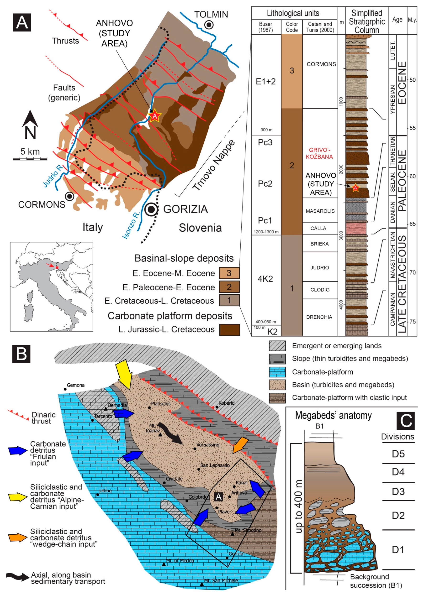
Figure 1). Here a NW-striking, regional monocline dipping towards the SW is cut by thrusts and faults with a main NW-SE Dinaric trend. The Friuli Carbonate Platform was located at the southern boundary of the Julian—Slovenian Basin, forming a passive, distal margin relatively close to the paleo-Dinaric deformational front on the opposite NE side [
1,
2].
In this paleogeographic framework, the syn- and post-tectonic carbonate-platform successions of the Trnovo nappe represent the shallower NE equivalent of the relatively deep-water turbiditic infilling of the coeval Julian—Slovenian Basin to the SW during the Late Cretaceous—Paleogene time. In this time span, the Julian—Slovenian Basin and the equivalent outer foredeep basins (e.g., “Dinaric Foreland Flysch Basin" system from Trieste/Koper to southern Dalmatia and Montenegro [
6]) developed in narrow belts, recording a progressive evolution from an outer foreland to a complex inner foredeep setting, characterized by advancing thrust-top, piggy-back and transpressional/transtensional basin systems [
1,
2,
6]. The depositional setting has been reconstructed as a system of elongated basins arranged in a NW-SE direction [
5], internally segmented by slightly transverse and longitudinal intrabasinal ridges. These submarine carbonate ridges [
10], nowadays preserved and roughly aligned between Morsko and Trieste, appear to be structurally controlled (i.e., fault-bounded) and are inferred to represent paleobathymetric highs that isolate intra-platform and intra-slope basin systems characterized by interconnected depocenters [
9]. By analogy with the overall geodynamic and depositional setting, these isolated intrabasinal structures may represent the equivalent of the patchy carbonate-platforms observed for instance in the SW China Sea [
11].
The Anhovo depocenter, which represents the focus of this study (see
Figure 1A), lies between two Cretaceous fault-bounded blocks, the Jelenk structure to the NE and the Sabotin—Hruševje structure to the SW [
12]. The vast majority of the sediment gravity flows spread out along the elongated axis of the basin, delivering radially sourced, mixed carbonate and siliciclastic material [
8,
9].
2.1. General Megabeds’ Anatomy
The Paleocene—Eocene sedimentary succession recorded within these basins (
Figure 1A), informally named Grivò Flysch in Italy and Kozbana Flysch in Slovenia, contains at least 25 major carbonate-megabreccia units [
13]. These bodies are encased in a background succession comprising carbonate, siliciclastic and mixed turbidites deposited in a mid-water depth, base of slope—basin plain setting [
2]. The Rodez, Podbrdo, Perunk 1 and 2 units of the Kozbana Flysch investigated in this work approximately correlate to the stratigraphic interval comprised between the Ioanaz and Vernasso megabeds in the Grivò Flysch [
1,
2,
9].
These carbonate megabeds fall in the field of the so-called megabreccias, megaturbidites or olistolith swarms, following the nomenclature developed by reference [
14,
15,
16,
17]. The thickness of the investigated units spans from meters to tens of meters for the smallest megabeds, to maximum values of hundreds of meters for the largest ones [
2,
8]. As depicted in the detailed log of
Figure 1B, the general internal organization is made of up to five divisions, which from base to top are as follows [
2,
8]:
Division 1, calcareous breccias embedding oversized carbonate slide blocks (i.e., non-dissociated slide masses) (D1);
Division 2, calcareous breccias enclosing deformed, bedded siliciclastic—carbonate and marly slide blocks (D2);
Division 3, massive to crudely laminated, graded calcareous breccias and calcirudites (D3);
Division 4, graded, laminated fine- to coarse-grained calcareous sandstone and calcarentites (D4);
Division 5, massive/laminated marlstone (D5).
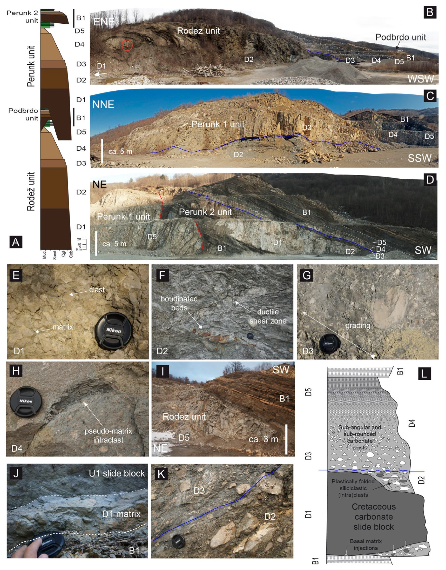
In general, breccias of Divisions 1 and 2 are matrix supported, whereas those of Division 3 are clast supported (
Figure 2). They consist of sub-rounded and sub-angular carbonate clasts from millimeters to centimeters, with a crude normal grading. The embedded slide blocks range in size from meters to hundreds of meters, with the ones in the Division 1 generally having the largest sizes. Such blocks derive from the disaggregation of the Mesozoic stratigraphic succession of the main Mesozoic Friuli Carbonate Platform, and of the coeval, minor ones rimming the basin to the NW/SW and SE/NE (see e.g., reference [
9]). The breccia clasts, including isolated bioclasts and rudist fossils, are prevailingly sourced from these carbonate-platforms, with the finer-grained part of the matrix deriving from the mixed siliciclastic—carbonate slope. The smaller blocks of Division 2 comprise folded and deformed, ripped-up rafts of the substratum, being mainly sourced from intra-basinal units, almost coeval with the bodies´ emplacement.
Microscale observations on the sedimentary matrix (either hosting and injecting the slide blocks) indicate an overall “particle-in-matrix” fabric, no breakage at grain-to-grain contacts, micro-injections of matrix into particles, pseudo-matrix intraclasts and hydroplastic, and fluidal structures. All these features suggest independent grain flow in overpressured fluid condition as the main deformation mechanism, and also testify the original unlithified state of the sediment involved and the catastrophic nature of the process (see
Figure 2).
Fluidal and overpressured conditions characterize the background breccia matrix, as testified by the lateral and vertical breccia injections into the enclosed slide blocks, and the giant fluid escape structures deforming the upper boundary of Division 2 below Division 3 (see e.g., reference [
9]).
This internal partition of the megabeds is likely due to the frontal erosion of the substrate operated during Division 1 emplacement and the consequent incorporation of the material in Division 2 [
9], as also suggested by references [
14,
15,
16] for the Eocene Hecho Group “Megaturbidites” of the Jaca Basin in the south-central Pyrenees of Spain. It is notable that between both sets of carbonate megabeds there is a perfect matching of the internal subdivisions in terms of stratigraphic position, compositions, discrete elements size and fabric (as for the conceptual comparison with the Bouma sequence outlined by reference [
18]), pointing out the same basic genetic processes (see e.g., references [
9,
14,
15,
16,
19,
20]). Remarkably, also the timespan (Paleocene—Eocene) and the overall geodynamic/physiographic setting (i.e., inner foredeep system of an evolving fold-and-thrust belt foreland) are comparable.
Given the economic interest of the cement and stone industry in the productive, high-quality marlstone (Division 5), calcirudite (Division 4) and calcarenite (Division 3) divisions [
21], these large bodies have been extensively excavated [
22] in relatively large open-pit quarries and thus they are outstandingly exposed in clean, laterally and vertically continuous and almost three-dimensional outcrops (see
Figure 2 and
Figure 3).
2.2. The Case Studies
The Anhovo quarry is located on the left side of the Isonzo Valley (46°3’42.93” N, 13°37’58.14” E), about 20 km N of Nova Gorica, and it covers an area of about 1.3 km
2 (including the Rodez and Perunk quarry segments). The area is bordered to the E by the Trnovo plateau and to the W by the Kanalski-Kolovrat ridge. This area is crossed by two regional faults [
23] separating the lower and upper Paleocene deposits, and involving Lower Cretaceous limestone [
7].
Following the local stratigraphic subdivision into single ideal “cyclothems” characterized by recurrent stacking patterns, each of which corresponds to single megabreccia units and the associated “normal” sedimentary succession on top [
8], the investigated succession covers about 2 “cyclothems”, which are associated to the Rodez and Perunk 1 units. Smaller “cyclothems” (i.e., the Podbrdo and Perunk 2 units) also occur, being comprised within the terminal part (background sedimentary succession B1) of the Rodež and Perunk 1 units, respectively.
As described by reference [
9], the limestone blocks and substrate rip-ups reaching 100 m in length and 30 m in height were found within Division 1 of the Rodez unit, but Cretaceous slide blocks up to 250 m across and substrate rip-ups of ca. 1400 m in length and 100 m in thickness have also been documented [
8]. The slide blocks in the Perunk 1 and 2 units consist of exotic Cretaceous limestone—marlstone and intrabasinal, Paleocene—Lower Eocene shallow water wackestones/packstones [
23]. These blocks show sub-angular, lozenge-like shapes being always associated with relatively high amounts of breccia, whereas the rip-ups comprise fragments of the coeval slope—basin plain succession, including resedimented carbonates in the form of smaller megabeds/megaturbidites (see
Figure 2C). The blocks of this unit show more complex shapes, usually with low height/length (H/L) ratio, being plastically deformed into detached, rootless folds. The slump-like folds deforming these rip-ups show marked curvilinear axes, which locally result in well-developed mesoscopic sheath folds in three-dimensional view (see
Figure 2A). Evidence of liquidization (i.e., liquefaction plus fluidization processes; see e.g., reference [
24] and references therein) is found in sandy layers within the folded rip-ups, usually testified by the development of over-thickened fold hinges, and shear-related, layer-parallel asymmetric boudinage on the limbs. In turn, hydroplastic shearing of the muddy intervals (e.g., pseudo SC- and sigma-type structures) is commonly observed. Notably, at the entire outcrop scale, an apparent internal partition of the structural elements within Division 2 of the Rodez unit can be recognized, with synclinal folds dominating in the lower part and anticlinal folds in the upper part (see reference [
9]).
Within Division 2, sedimentary injection-type structures filled with the breccia matrix commonly penetrate the slide blocks. Such wedge-shaped sedimentary intrusions are distributed radially to the folds’ flexure axes, suggesting the coeval generation of folding and injections, and a relatively strong rheological-mechanical contrast between injected slide blocks and enclosing matrix (i.e., pseudo-fracturing versus liquidization, respectively, see reference [
9]). In particular, these sedimentary injections suggest a parent flexural—slip-type, layer-parallel shearing developed in overall hydroplastic conditions at high strain rates, with marked rheological-mechanical contrast of the involved elements. Along these injection structures, changes in the grain size of the intruded breccia have been observed, with fine-grained portions (clay-marl) in the narrowest zones and within the cusps, and coarse-grained breccia in the widest ones, suggesting a mechanical sieving and elutriation of the finer particles, due to forced matrix flow (see reference [
9,
25]). The same structures are also found along detached folds’ axial planes, in association with asymmetric boudinage, pinch-and-swell, sigma-type and SC-type structures (see
Figure 2E). Sometimes they develop secondary off-shooting injections splaying out from the main one, especially close to the hinge zones. Moreover, cm- to m-sized sedimentary cusps are observed to wedge out downward crosscutting calcarentitic and calciruditic material from Division 3 into Division 2. At a larger scale, dome-like structures up to ten of meters in size are observed to deform the contact between Divisions 2 and 3, producing marked thickness variations of these units over short distances (see references [
9,
25]).
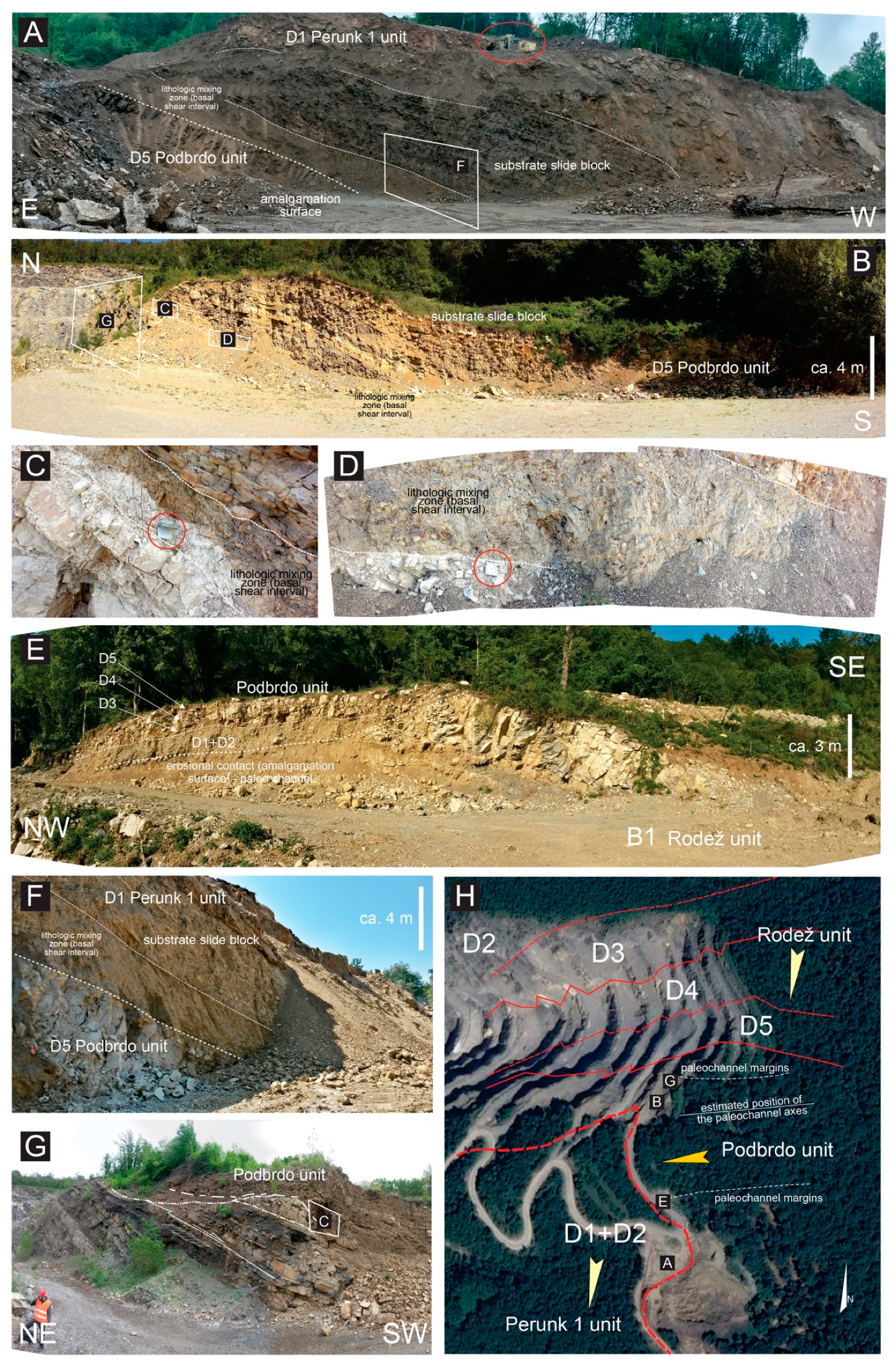
2.3. Relationship with the Host Sedimentary Succession
Shallow and deep basal erosion (i.e., seafloor scouring and consequent incorporation of loose to poorly lithified sediments) and syn-/post-depositional deformation of the substrate (i.e., hydroplastic folding and plastic, low-angle shear zone) can be well observed in the investigated megabeds (
Figure 3).
Combining structural-stratigraphic analyses performed on Division 2 of megabeds and the compositional/provenance data available from the literature [
1,
2], multiple paleotransport directions can be drawn across the basin. For the Anhovo study area a predominant paleotransport direction toward the S-SW can be outlined [
9]. Shear zones and folds are locally overprinted and crosscut by brittle ones, represented by shear fractures marked by calcite mineralization (mainly as shear fibrous/stepped veins), stylolites and slickenlines, that are in line with the regional-scale, ca. SW-striking Dinaric contractional stress regime [
9]. The substrate rip-ups of Division 2 are characterized by ductile, soft-sediment structures generated during the slide emplacement (both within and below the body), revealing a dominant SSE-directed paleotransport direction [
9].
The bed packages overlying the megabed units are made up by marly calciturbidite and dark shale, which record the recovery of the background sedimentation after the episodic mass transport events. These intervals also contain minor megabeds, represented by meter-thick, lens-shaped, channelized carbonate breccia deposits and mixed carbonate—siliciclastic debris flow bodies, which also display the same divisions as the main megabeds. These deposits show strongly erosional bases as well, scouring into the underlying succession down to 4–5 m. Notably, the levees and the inferred axis of these “channel fills” are roughly parallel to the margin of the large carbonate blocks occurring in the underlying units, suggesting relatively-long term relationships between mass transport processes and subsequent sedimentation (e.g., channel locations and paths controlled by location of underlying slide blocks).
3. Methods
Geo-electric resistivity data (tomographic technique) were acquired along three 2D ERT profiles with a total length of 6–7 km. Various combinations of electrical resistivity measurements were performed with the electrodes system (number of cables x 12 electrodes, a = 5 m, n = 1–25, Wenner). An approximately 60 m depth penetration was achieved with this analysis using an automatic commutating digital resistance meter SYSCAL-R2 (BRGM). Automatic control of the measurement process was also implemented. Geo-electric resistance probing (Schlumberger, the largest AB/2 of 8–100 m) with the SYSCAL-R2 instrumentation was applied. The combined database of standard electrical measurements and geo-electric probing at selected sites were used to produce the three 2D ETR profiles.
Along with the geo-electric measurements, samples were systematically taken for geochemical analyses (XRF), used for industrial scale production. Such analyses were performed on marly clasts from Division 2 and 3 of the Perunk 1 unit (samples Pe1 to Pe10) and the marlstones from Division 5 of the Podbrdo unit (samples Po1 to Po5; locations shown in
Figure 4A). Part of the collected samples were crushed in a laboratory mill while the remaining part was used for further sedimentological analysis, along with manual counting (unit per area) of nanoplankton microfossils. An XRF analyzer ARL 848 has been used for determination of major oxides (SiO
2, Al
2O
3, Fe
2O
3, CaO, MgO, K
2O, Na
2O, SO
3) as well as heavy metals (V, Ba, Ni, Cr and Mn). The voltage and current parameters of the X-ray tube was set at 30 kV and 80 mA with the recording time at 40 s.
In order to estimate the relationship between the basinal sedimentation and sediment sources, the degree of weathering (Chemical Index of Alteration, CIA; [
26]), carbonate (CaCO
3) content and Cr-V/Mn element ratios, were combinedly correlated [
27,
28,
29,
30]. CaO
TOT is determined on the basis of XRF analysis, whereas CaO
TG is calculated from the emitted CO
2 during the decomposition of carbonate minerals. The proportion of CaO bound to non-carbonate minerals and considered in the CIA equation is determined as CaO* = CaO
TOT − CaO
TG. The value of CIA was determined as CaO* amount, which is the CaO bounded to non-carbonate mineral assemblages. In interpreting the source of sediments, we considered the interrelationship between the V/Mn and Cr/Ni and the absolute proportion of carbonate.
4. Results
The obtained XRF results show that the D2-D3 and D5 of the Perunk 1 and Podbrdo unit, respectively, differ in terms of SiO
2, Al
2O, Fe
2O
3, CaO* and K
2O (see
Figure 4B), Cr, V, Mn, Ni and Ba content (see
Figure 4C), as well as in degree of weathering, estimated on the basis of the CIA fraction, and micro-fossiliferous content (see
Figure 4D,E). In general, the Podbrdo unit samples show a relatively more homogeneous distribution of major and trace elements, CIA, and nannoplankton fossils content that the Perunk 1 ones, highlighting the lithological heterogeneity of the latter (i.e., D5 marlstones vs. D2-D3 breccias). In particular the CIA show an inverse correlation with the carbonate (and mixed siliciclastic) fraction, and a direct correlation with the amount of heavy metals, suggesting generating alteration (dissolution) processes (see
Figure 4F,G). On the same line, the number of counted microfossils shows an inverse correlation with the amount of CaO
TOT, suggesting just a partial in-situ biogenic carbonate contribution. In this framework the Podbrdo samples show less weathering, with higher carbonate and lower heavy metals content, whereas the Perunk unit ones are characterized by an opposite trend, with more data spread likely due to the higher heterogeneity (i.e., D5 vs. D2-D3). These data were than compared with published databases on the local Paleogene sedimentary succession of SW Slovenia (Vipava valley and Brkini area) [
31,
32,
33,
34].
The interpretation of the electric resistivity profiles is supported by surface observations, with clear trends in the resistivity contours, attributed to the internal subdivisions of the megabeds, which also testify their generally good lateral continuity in the subsurface. The general stratigraphy in profiles 1 and 2 (see
Figure 5) is characterized by SW-dipping bedding almost parallel to the slope, whereas in the orthogonal profile 3, the general dip is toward the SE with gentler inclinations. Two distinct and approximately bedding-parallel shear zones are interpreted in profile 1 and partly in profile 2, biasing the internal architecture and thickness of the internal divisions of the megabeds.
In general, the internal subdivisions as well as the background sedimentary interval comprised between major megabeds are recognizable in ERT profiles, testifying their overall tabular attitude with little thickness variations. Internal elements such as major slide blocks are also identifiable as increased resistivity anomalies as well as lateral erosional relationships expressed as ramps in the basal shear zone of the megabeds, which deeply incise the background stratigraphy in between the main units (see profiles 1 and 2 in
Figure 5).
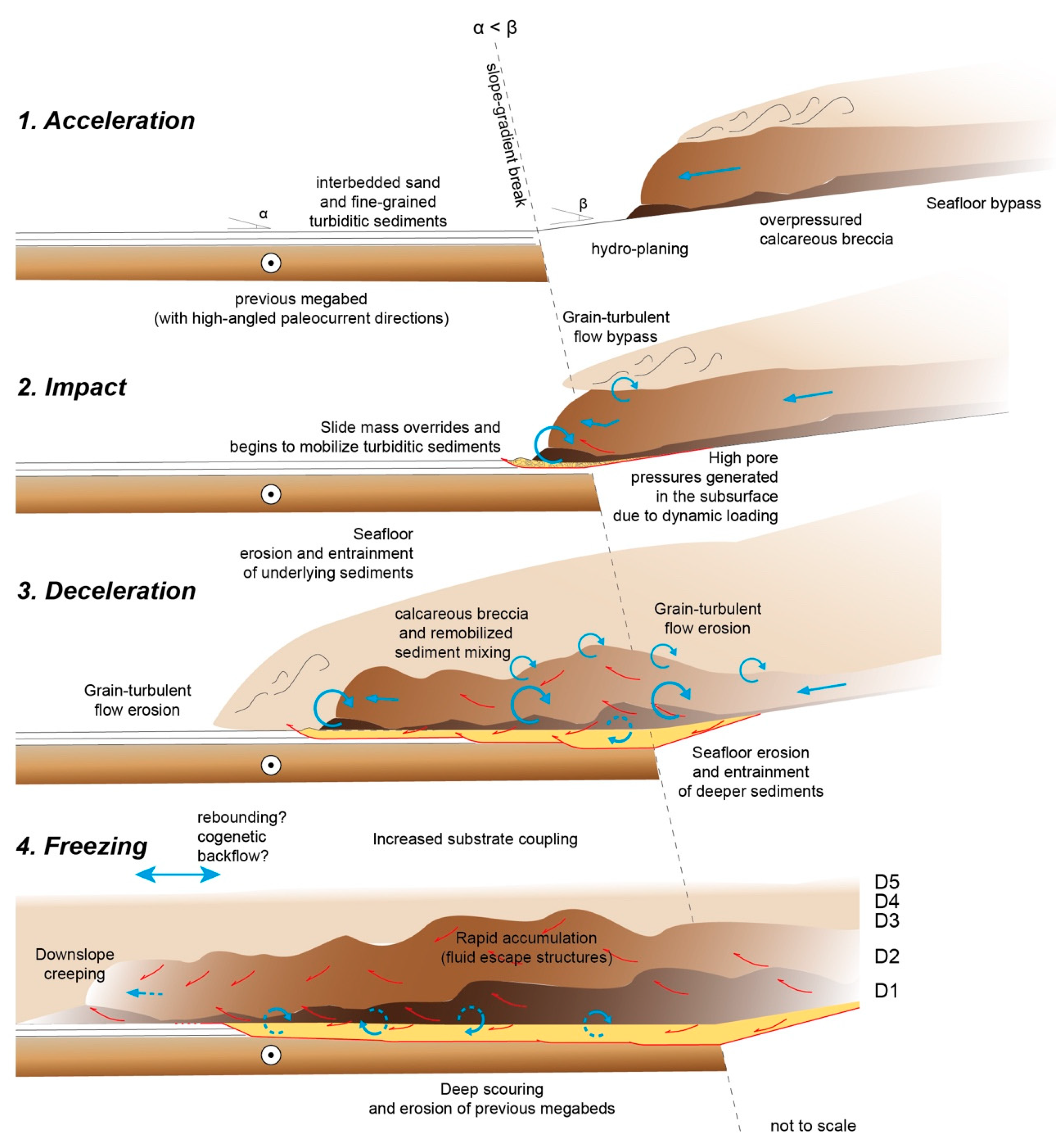
5. Discussion and Updated Interpretations
The inferred process generating the Julian—Slovenian Basin megabeds is represented by a composite slide-flow made up by the combination of a lower, debris-blocky flow/avalanche [
20] bearing out-sized blocks (Division 1 and 2), and by an upper grain-flow (Division 3 and 4), capped in turn by an associated fully turbulent flow (Division 5), as depicted in
Figure 6 see also [
1,
2,
9]. Division 1 itself represents the expression of a bipartite mass flow with a lower, discontinuous and relatively thin matrix-rich part, and a thicker, continuous, upper, block-rich part that is also volumetrically dominant. These internal subdivisions are further characterized by different types of texture, especially in terms of matrix- versus clast-supported framework, sorting and lithological mixing. Given this block-in-matrix fabric made up by mixed intrabasinal (native) and extrabasinal (exotic) elements, these units can be classified as sedimentary mélanges (or olistostromes), and represent fossil analogs of the modern mass transport depsits and complexes [
3,
4].
The proposed mechanisms inferred to explain the transport and accumulation of such deposits (see
Figure 6) imply a combination of: (i) matrix (sediment+water) overpressure from hydroplaning to shear wetting and liquidization, (ii) dispersive pressure due to grain-to-grain interactions, and (iii) buoyant forces able to sustain discrete elements less dense with respect to the enclosing hyper-concentrated matrix (e.g., vuggy biohermal carbonates, water-saturated rip-ups). The maximum erosive capacity of these slide bodies is thought to be attained at slope gradient breaks (see
Figure 6, stages 2–3) during slide—flow transformations, and when the slide mass decelerates, dissipating its internal fluid overpressure (e.g., base of the slope—basin plain transition, impact against paleo-bathymetric highs; [
9,
20,
24]). This mechanism enhances localized scouring of the seafloor, allowing entrainment of large portions of the substratum.
The emplacement of the lower parts of the slide mass (Divisions 1 and 2) is achieved through differential movements of the internal components, with shear-lubrication and flow of the overpressured matrix, along with the passive hydroplastic deformation of the bedded rafts. The subsequent (pure) flow stage expressed by the upper slide parts (Division 3, 4 and 5) eroded and draped the uneven topography atop of the block-dominated divisions (Divisions 1 and 2), smoothening the local physiography and flattening the basin floor for the recovery of the background regime (
Figure 6).
Mesoscale sedimentary injections into the slide blocks of Divisions 1 and 2 testify fluid overpressure conditions developed within the breccia matrix, suggesting high strain rates and a dynamic rheological-mechanical contrast between the elasto-plastic (pseudo-brittle/brittle) slide blocks, and the surrounding, visco-plastic (pseudo-fluid) matrix. The occurrence at the microscale of the same structures confirms the fluid overpressure-related liquidized state of the background sedimentary breccia matrix [
9].
Post-depositional processes further complicate the overall structural framework, deforming and modifying primary structures. These processes, acting progressively from early slide accumulation to deep burial, can be summarized in: (1) accommodation, (2) compaction, (3) diagenesis, (4) tectonics and (5) exhumation and surficial processes.
The retention of excess pore pressure in the matrix of thick, “frozen” slide mass is expected to last a relatively long time after sedimentation, as suggested by experiments and numerical modeling [
35]. Accordingly, this slow dissipation is inferred to control early post-depositional processes such as accommodation and compaction as supported by the occurrence of fluid escape structures and shearing at the Division 2–3 boundary, folded and deformed breccia matrix injections, and folds interference, which are thought to record early post-depositional creeping of the entire slide mass (see reference [
9]). On the same line, the channelized carbonate breccia bodies that characterize the background sedimentary intervals atop the megabeds are systematically located above the margins of major slide blocks, suggesting that the differential compaction between rigid slide blocks and the plastic matrix controlled the subsequent deposition of the overlying beds.
Due to the complex interaction of different tectonic contributions (i.e., Alpine and Dinaric) and the particular Paleocene—Eocene environmental context, several types of short- and long-term triggering mechanisms could be invoked as possible causes for the emplacement of the Paleocene—Eocene carbonate megabeds of the Julian—Slovenian Basin: (1) seismic shocks, (2) progressive tectonic oversteepening of the leading slopes (both on the external foreland “passive” margin and on the internal “active” margin due to flexural loading and fold-and-thrust belt growth, respectively), (3) long-term variations of the local to regional hydrogeologic regime, (4) first- to second-order sea level changes, and (5) bolide impacts [
36,
37].
However, the most likely and classically proposed triggering mechanism is the seismic shock, crucial pre-conditioning factors could be pointed out for the investigated case studies. Such long-term triggers might be directly or indirectly related to the well-documented, major climatic shift recognized during the Paleocene—Eocene [
38], such as: (1) extreme storm wave loading-unloading cycles, (2) increasing and redistribution of sediment delivery, (3) floods, (4) second- to third-order sea level changes, (5) local, temporary changes in the local paleo-hydrologic systems.
In terms of geochemical signature, elements such as Cr, V and Ni are typical for mafic and ultramafic igneous rocks. Their occurrence in larger quantities (Cr > 150 ppm and Ni > 100 ppm) in sedimentary rocks usually indicates a hinterland sediment sources, commonly corresponding to exhumed ophiolithic complexes [
39]. At oxic conditions, as those inferred for Cluster A and partly Cluster B, V occurs in immobile form in the pelagic and hemipelagic sediments, being closely associated to Mn in anoxic conditions, as interpreted for Cluster C [
40]. Correlation between Cr and Ni (which is an important nutrient in the marine biogeochemical cycle in the form of mobile cation Ni
2+ [
21,
41]) is remarkable, indicating a hinterland affinity according to trace elements in the marly sediments (see
Figure 4). This provenance from ultramafic and mafic rock complexes to the NW of the Dinaric carbonate-platform supports the interpretations advanced by references [
2,
34]. Also, Mn plays an important role in the biogeochemical cycle by marking the transitional boundaries of the reduction environment, which may be located at the water-sediment interface, and within or above the seafloor [
42]. The proportion of Mn in the marine environment in hydroxide form is often conditioned by the influence of fluvial input [
43]. This hydrolyzed form of Mn in the marine environment has
4+ valence and tends to precipitate. At anoxic condition Mn
4+ is reverted to Mn
2+, and increased concentration indicates low carbonate sedimentation in the environment. This is part confirmed by the correlation between the number of preserved skeletons and the weathering degree CIA (see
Figure 4B,C). Cr is mobile in marine anoxic environments, and during burial, it can escape diagenesis through diffusion, entering again in a new geochemical cycle. Notably, local enrichment of elements such as Cr, V and Ni is also inferred as a proxy for bolide/meteorite impacts (see below) [
44].
The appearance of Cluster A, Cluster B and Cluster C populations against the number of preserved micro-fossils (see
Figure 4B), document preservation and mixing of resedimented carbonate micro-clasts [
21] coming from different sedimentary environments (e.g., gravitational versus hemipelagic sedimentary processes). Moreover, thermal analyzes show that the decarbonatization of hemipelagic marls is attained at lower temperatures than the hemiturbiditic ones [
29], testifying a depositional environment characterized by concomitant hemipelagic and turbiditic sedimentation. Since the number of preserved microfossils is used as proxy for diagenetic carbonate dissolution and remobilization due to the occurrence of oxic/anoxic conditions [
42], Cluster B and Cluster C populations seem to point out two different deep-sea settings.
The V/Mn increases along with chemical weathering defined by CIA (
Figure 4C), pointing out possible adsorption of detrital (terrestrial) and/or intrabasinal organic compounds [
45]. In the presence of anaerobic bacteria and H
2S, V assumes
3+ valence [
40,
41,
42] and can pass to the oxide or hydroxyl insoluble form. In fact, during the diagenesis, the V
3+ form can replace Al
3+ in the octahedral sites of autogenic clay minerals. The V/Mn ratio has the opposite trends as Cr with respect to the rate of chemical weathering defined by CIA, confirming an anaerobic environment of formation.
6. Conclusions
The carbonate megabreccia units of the Paleogene Julian—Slovenian Basin represent large-scale, basin-wide sedimentary mélanges. They corresponds to excellent ancient analogues of mass-transport events caused by the collapse of shallow-water carbonate-platforms, located in marginal shelfal areas and redeposited into a relatively deep and evolving inner foredeep basin system. Accordingly, they also represent one of the best-exposed counterparts of modern platform collapses and failures observed in the major modern reef barriers (e.g., reference [
46]). These catastrophic events generated bi-tripartite, fast moving masses composed of a lower cohesive, blocky/debris flow part [
15] with slide blocks exceeding 100 m across, that are able to deeply erode the overridden seafloor and incorporate large amounts of ripped off material, and an upper turbulent flow, in turn able to erode the underlying blocky/debris flow. During their downslope motion, internal and basal friction forces were dissipated by fluid overpressure conditions provided by the undrained, fine-grained matrix, allowing the slide mass to accelerate and move fast until it reached the slope—basin plain transition. At this point, the hydraulic jump of the dense-to-turbulent flow part (i.e., Divisions 3, 4 and 5) also caused partial syn-depositional erosion of the upper part of the lower Division 2.
Such bodies are widespread in the investigated Paleocene—Eocene sedimentary succession, also in other localities such as the south-central Pyrenees in Spain [
14,
15,
16,
17], suggesting some causal relationship and offering a new challenge in the long-distance characterization of this time span across the northern Mediterranean region. Another speculative but fascinating situation arising from published geochemical analyses concerns the possible relationships of these units with the increased input of cosmic material documented for that period [
47], and precisely in the same area [
36]. In this framework, the heterogeneous carbonate mineralization and high proportion of V in the Cluster C marlstone population, in addition to its correlation with Cr concentration, possibly suggest the intriguing possibility of a far, inland sedimentary input in the form of co-genetic tsunami back-flows.
Our findings document that the integrated study of sedimentary mélanges and olistostromes, as ancient analogues of mass transport deposits, may provide useful information to better understand submarine landslide processes in modern continental margins.

 ,
, 


