Novel Nozzle Shapes for Synthetic Jet Actuators Intended to Enhance Jet Momentum Flux


Institute of Thermomechanics of the Czech Academy of Sciences, Dolejškova 5, 182 00 Prague, Czech Republic
*
Author to whom correspondence should be addressed.
Actuators 2018, 7(3), 53; https://doi.org/10.3390/act7030053
Submission received: 27 July 2018
/
Revised: 14 August 2018
/
Accepted: 25 August 2018
/
Published: 28 August 2018
(This article belongs to the Special Issue Synthetic Jet Actuators)
Abstract
:An axisymmetric synthetic jet actuator based on a loudspeaker and five types of flanged nozzles were experimentally tested and compared. The first (reference) type of nozzle was a common sharp-edged circular hole. The second type had a rounded lip on the inside. The third nozzle type was assembled from these two types of nozzles—it had a rounded lip on the inside and straight section on the outside. The fourth nozzle was assembled using orifice plates such that the rounded lips were at both inner and outer nozzle ends. The last nozzle was equipped with an auxiliary nozzle plate placed at a small distance downstream of the main nozzle. The actuators with particular nozzles were tested by direct measurement of the synthetic jet (SJ) time-mean thrust using precision scales. Velocity profiles at the actuator nozzle exit were measured by a hot-wire anemometer. Experiments were performed at eight power levels and at the actuator resonance frequency. The highest momentum flux was achieved by the nozzle equipped with an auxiliary nozzle plate. Namely, an enhancement was approximately 31% in comparison with an effect of the reference nozzle at the same input power. Furthermore, based on the cavity pressure and the experimental velocity profiles, parameters for a lumped element model (mass of moving fluid and pressure loss coefficient) were evaluated. These values were studied as functions of the dimensionless stroke length.
1. Introduction
Synthetic jets (SJs) are fluid flows created by fluid pulsations and are formed in free space behind a nozzle [1]. The fluid is periodically pushed and pulled through the nozzle with one end exiting into a cavity. The source of the pulsations is an oscillating diaphragm that bounds one side of the cavity. The nozzle is the only inlet/outlet into/out of the cavity; therefore, the time-mean mass flux through the nozzle is zero. This is why SJs are often referred to as zero-net-mass-flux jets [2]. The momentum flux along the nozzle axis, however, is non-zero. It causes the flow to continue downstream of the nozzle exit, forming a jet flow similar to the continuous jet.
Since the end of the last century, SJs have been intensively investigated and many potential applications have been proposed. The applications have been found in boundary-layer separation control [3,4,5,6,7,8,9] jet vectoring [10,11], and heat transfer enhancement [12,13,14,15]. A variant of the SJ, namely the non-zero-net-mass-flux jet (or hybrid SJ), has been investigated more recently [16,17,18,19].
For the synthetic jet actuators (SJA) based on elastic diaphragms (e.g., based on a loudspeaker or a piezoceramic membrane), when an energy balance is considered, the most advantageous operating conditions are found at resonance. Therefore, many studies focused on location and prediction of the SJ actuator resonance characteristics [20,21,22,23,24,25]. With an SJ actuator operated at resonance, other ways to enhance the exploitable outlet quantities, such as the jet thrust, still exist.
An augmentation of the jet thrust is the main topic of this work. Specifically, this paper investigates the axisymmetric SJ actuators based on a loudspeaker operating at the first resonance. Under these conditions, five types of flanged nozzles were tested within the actuator. The first nozzle was a common sharp-edged circular hole. The remaining nozzles combined rounded lips at the nozzle ends. An auxiliary nozzle plate placed slightly downstream of the main nozzle exit was tested, as well. The nozzles were designed to decrease the hydraulic resistance and, therefore, enhance the resulting jet momentum flux (jet thrust). Using the SJ time-mean thrust measurement, the most effective nozzle design was determined.
2. Problem Parameters
2.1. Basic Synthetic Jet Dimensionless Parameters
A harmonically driven SJ can be quantified by two dimensionless parameters, which include the Reynolds number, Re, and the dimensionless stroke length, L0/Dn. The definitions of these parameters are as follows:
where Dn is the nozzle diameter of the SJA (see Figure 1a,b and a description in Section 3.1), f is the driving frequency of the actuator’s harmonic excitation, and ν is the kinematic viscosity of the working fluid. The characteristic time-mean velocity is denoted U0 in Equation (1) and is defined in the next section.
2.2. Synthetic Jet Integral Quantities
A basic integral quantity, upon which the Reynolds number and dimensionless stroke length are based, is the SJ characteristic velocity, U0. Assuming an axisymmetric SJ, the standard characteristic velocity is defined as follows [1]:
where T = 1/f is the excitation period, TE is the extrusion stroke duration, and un is the fluid velocity at the nozzle exit cross-sectional area. The phase position of the velocity un with respect to the time cycle origin is such that the inner integral of Equation (2) is positive for the whole integration interval (0, TE). The indicated cylindrical coordinate system (x, r) is introduced in Figure 1a,b.
The most important observed integral quantity is the SJ time-mean thrust, M0, with a magnitude that can be measured directly using precision scales. The experiment assumes a vertical, upward-issuing SJ, with an actuator placed on a precision scale. The action force related to the momentum flux is directed upward, and the reaction force (jet thrust) acting on the scale surface is directed downward and thus the jet thrust is measured. For particular measurement details, see Section 3.2.
Assuming that the velocity profiles are flat along the nozzle diameter (slug flow model) and the nozzle outlet velocity waveform is purely sinusoidal, the measured jet thrust can be used to evaluate the characteristic velocity, U0. Based on Equation (2), the velocity can be then approximated by the following formula [26,27]:
where ρ is the working fluid density. The velocity U0 obtained from Equation (3) was used to evaluate dimensionless stroke length according to Equation (1).
2.3. Parameters for Lumped Element Model
Lumped parameter models are often used to predict SJ outlet velocities or SJA optimized geometries [28,29,30]. Basic momentum equations of a SJA, which are based on lumped element approximation, have the following form [31]:
where md is the diaphragm mass, Kd is its spring constant, Sd is the diaphragm effective cross-sectional area, Bd is its damping and F(t) is the force, which excites the diaphragm oscillation. The diaphragm velocity and the velocity of the fluid inside the nozzle with cross-sectional area Sn are denoted as ud and un, respectively. The pressure difference between the cavity and ambiance is denoted as pc. The mn denotes the mass of the moving fluid inside and within the vicinity of the nozzle; ξ is the pressure loss coefficient across the cavity-nozzle-ambiance. These two parameters (mn and ξ) are unique for each of the tested nozzles and were obtained from measurements.
3. Measurement Methods
3.1. The Synthetic Jet Actuator
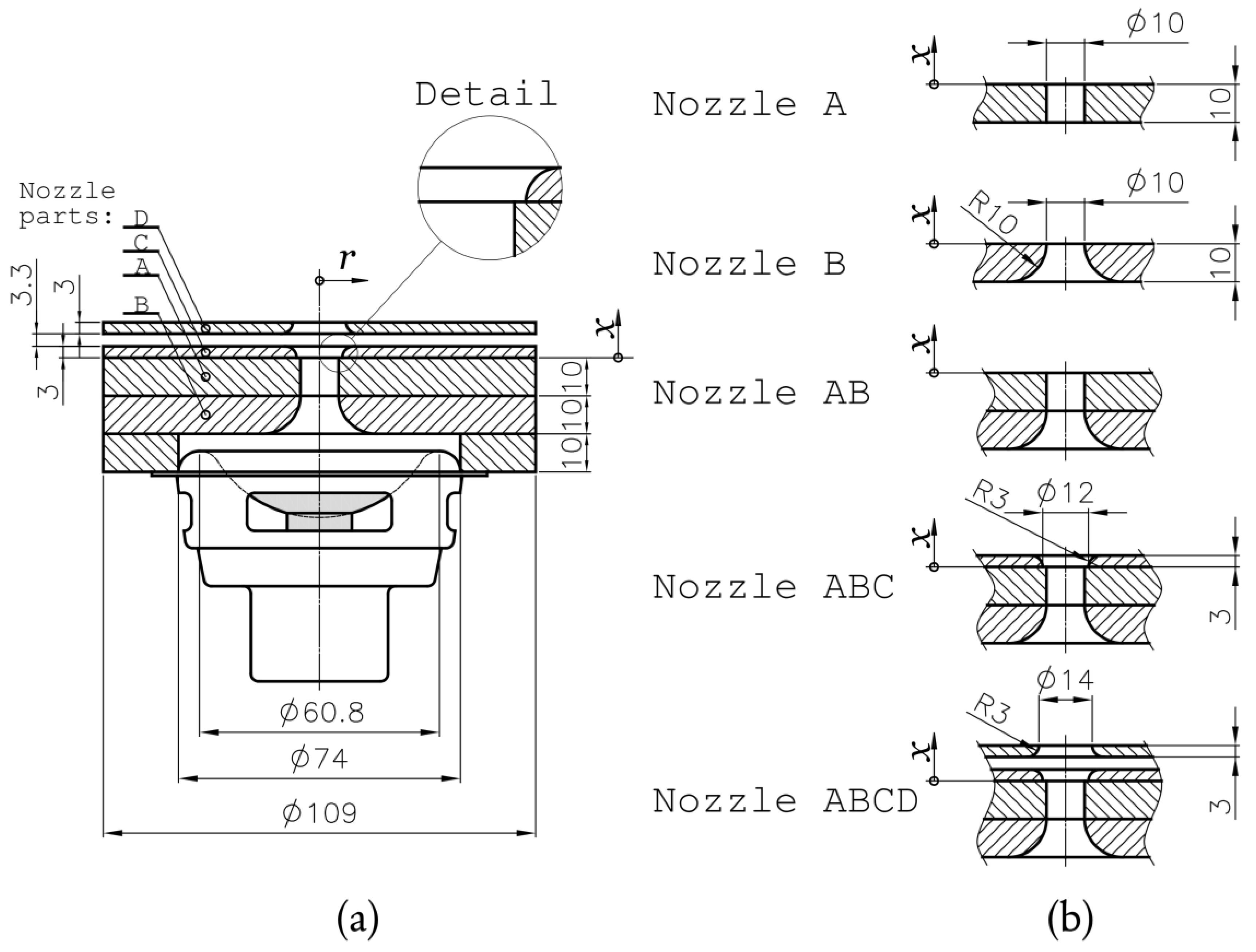
Figure 1a shows a schematic view of the tested SJA that was operated with air as the working fluid (for fluid properties, see Table 1). The actuator was based on an Aurasound NS3-193-8A loudspeaker with a harmonically driven diaphragm producing pressure oscillations in the cavity. Five axisymmetric nozzles were tested as seen in Figure 1b. The narrowest diameter within each of the tested nozzles was consistently Dn = 10.0 mm.
- Nozzle AB was a combination of the previous nozzles. Note that an experimental study of similar nozzle geometries was done, e.g., by Nani and Smith [32].
- The fourth nozzle was denoted as ABC (it consists of three nozzle plates A+B+C, see Figure 1a) and had a special novel design with rounded lips at both inner and outer nozzle ends. A similar shape was tested by Lee and Goldstein [36] for a slot-type nozzle. However, this study’s nozzle was circular and equipped with a small step at the end of the straight nozzle section. This step promoted flow separation and prevented flow reattachment during extrusion stroke.
- The ABCD nozzle combined the design by Rylatt and O’Donovan [37] with the ABC nozzle. The nozzle contained an auxiliary outer nozzle—denoted as part D, see Figure 1a. The auxiliary nozzle had a greater diameter (12.0 mm) than Dn = 10.0 mm and was placed 3.3 mm downstream from the exit of nozzle ABC, see Figure 1a. The rounded edge of the part D was oriented towards the actuator outlet, helping to direct the radially dispersed momentum flux along the x-axis.
During all experiments, the actuator was supplied with an electric current generated by an Agilent 33220A function generator and amplified by a homemade constant-gain-amplifier. More details of the experiment were presented in [38]. The experimental investigation was performed at eight input power levels between 0.13 and 2.26 W (for particular power values see Table 1). For each combination of the applied power and the nozzle geometry, the optimum driving frequency was first found with respect to a maximum jet thrust, which was then evaluated using a precision scale.
3.2. Data Acquisition and Measurement Methods
3.2.1. Measurement of the Jet Thrust Using Precision Scales
Measurements of integral forces is a classical technique in experimental fluid mechanics. It has been employed since the turn of the 19th and 20th centuries in wind tunnel testing. Surprisingly, such measurements in SJ studies are rather rare yet.
Probably the first journal paper which described measurements of integral forces by precision scales for SJA design was presented by Trávníček et al. [39]. Another investigation, which was supported by this method, was presented by Kooijman and Ouweltjes [40]. The method was used by Broučková and Trávníček [26] and a reasonable agreement with the hot-wire velocity data was concluded. Another SJ measurement was performed by Trávníček and Broučková [41] for SJA with a bio-inspired actuator with an oscillating nozzle lip. Another investigation of SJs, which employed this method, was performed by Kordík and Trávníček [38].
More recently, the limits and accuracy of this method have been quantified by means of an independent hot-wire measurement and spatial–temporal integration of velocity profiles [42]. It was concluded that the thrust measurements by means of a precision scale yield a very good evaluation of the characteristic velocity, momentum, and kinetic energy fluxes. Namely, the maximum deviations between experimental data obtained by this method and reference hot-wire data have been evaluated [42]:
- For relatively weak SJs at the dimensionless stroke length of L0/Dn from 0.5 to 5 (i.e., including the vicinity of the SJ existence threshold), the maximum deviation is within ±5.4%.
- For stronger SJs at L0/Dn ≥ 5, the maximum deviation is only ±3.4%.
Following a detailed description of SJ measurements by precision scales [38,42], the SJA was placed on a Mettler Toledo PR8002 DR precision scale with nozzle directing the SJ upward. Before the actuator power input was turned on, the scale was reset. The chosen power input value was adjusted using a regulation loop driven by a personal computer. After adjustment of the power input and stabilization of the time-mean flow, the force (i.e., the seeming mass magnitude increase), due to the SJ time-mean momentum, was measured. The magnitude of SJ time-mean momentum was evaluated according to Newton’s third law of motion as follows:
where m0 is the value of the seeming mass due to the reaction force, and g is the magnitude of the gravitational acceleration, g = 9.80665 m/s2.
To check the desired power input into the actuator, the supplied electric current, i, and voltage, e, were acquired and sampled using an NI-PCI 6023E data acquisition device. The sampling frequency was 128·f, and the number of samples was 25,600.
The uncertainty of the jet thrust measurement method was evaluated in [38]: based on PR8002 DR precision scale resolution and data floating, the relative uncertainty of the measured thrust values is in the range of 2.8–6% (at 95% confidence level).
3.2.2. Hot-Wire and Cavity Pressure Measurements
Hot-wire measurement of the velocity profiles occurred at the narrowest neck of the tested nozzles. The velocity profiles were used here to evaluate the lumped model parameters. The velocity readings were measured using the hot-wire probe (55P16, DANTEC) and anemometer (MiniCTA 54T30, DANTEC). The experimental approach was as follows. The desired power level and frequency were tuned within the SJA, and the hot-wire probe was then placed at the nozzle outlet of the running actuator (the approximate probe position was x = 0.3 mm, for the coordinate system, see Figure 1a,b). Afterwards, the probe was traversed along the nozzle diameter. At 17 discrete points, the hot-wire signal from the anemometer was sampled in an NI-PCI 6023E data acquisition device. The settings of data acquisition device were the same as during precision scale experiment, i.e., sampling frequency was 128·f, and the number of samples was 25,600.
Along with velocity data, electric current, i, voltage, e, cavity pressure, pc, and the temperature of the working fluid (air) were sampled. Temperature measurements using a fast-response Pt100 sensor (PT100-SMD0805) were used for the temperature correction of the hot-wire data (for details, see [38]). The electrical inputs (i and e) were used to check and control the desired power input to the actuator.
The hot-wire probe calibration was completed within a velocity range of 0.15–50 m/s. The maximum relative uncertainty of a single velocity sample was less than 5% for velocities between 0.4 and 50 m/s. For very small velocities (0.15–0.4 m/s) the highest uncertainty was 17.0%. A more detailed description of the anemometer settings, probe calibration method, and uncertainty evaluation is available in [43].
The SJA cavity pressure measurements were performed using a homemade system based on a calibrated 1/4 inch (6.35 mm) high-pressure microphone (type 40BH) with a nominal sensitivity of 0.4 mV/Pa. The microphone, with preamplifier (type 26AC), was embedded inside an enlarged PMMA block in the vicinity of the loudspeaker. The pressure readings along with the velocity profiles were used to evaluate the parameters mn and ξ for the lumped parameter model (see Equation (4) and Appendix A).
4. Experimental Results
4.1. Frequency Characteristics
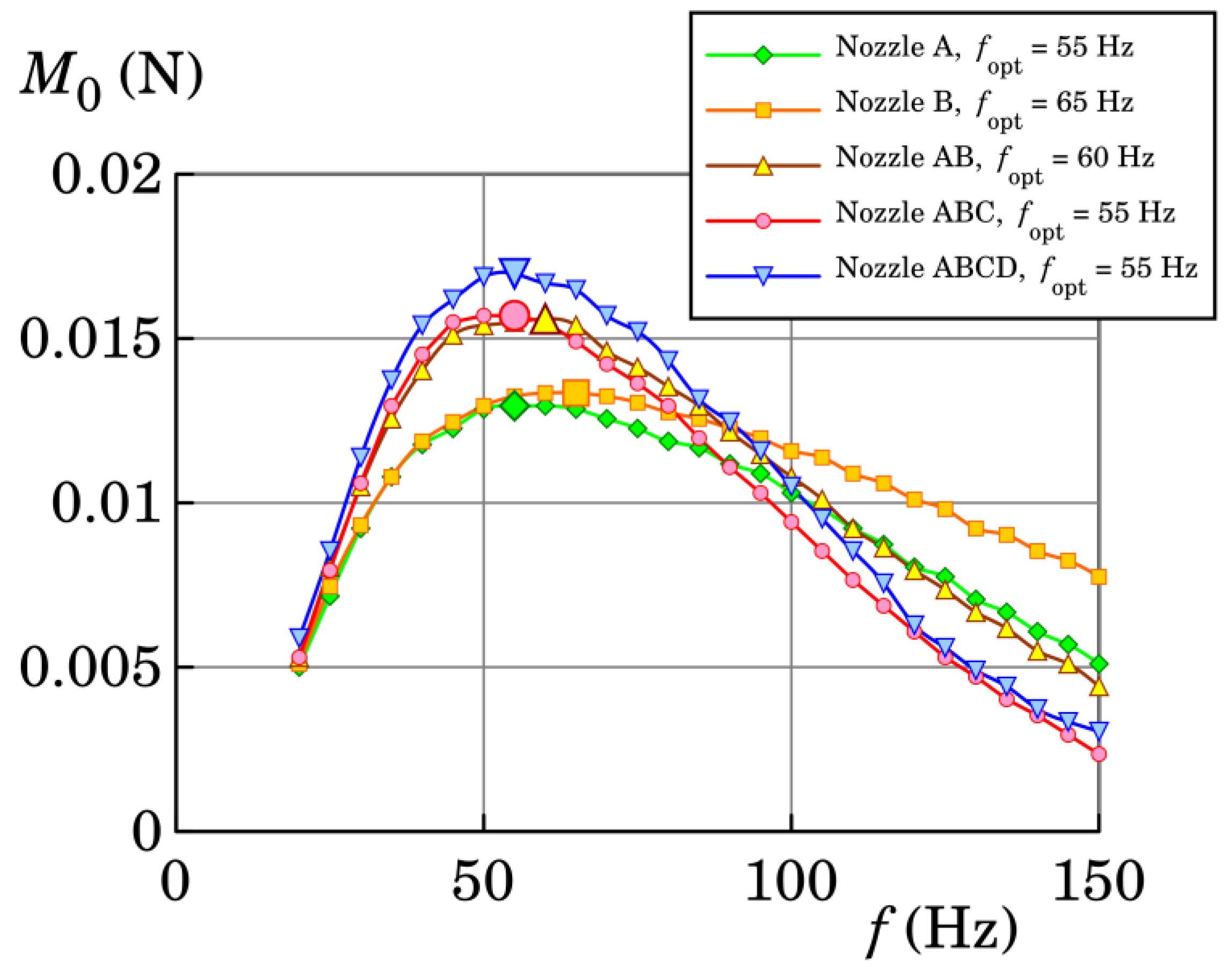
In order to determine the optimum frequency at which the synthetic jet thrust was a maximum, the frequency characteristics were measured. Measurements were taken using a precision scale within the frequency range of 20–150 Hz for one selected power input: 1.02 W. The resultant curves can be seen in Figure 2, where for each curve one peak indicates the maximum SJ thrust. The peak maxima are similar for each of the tested nozzle shapes. For A, ABC, and ABCD nozzles, the same optimum frequency was found of 55 Hz. In the case of the nozzle AB, the frequency with maximum thrust was 60 Hz and in case B it was 65 Hz (these frequencies are also summarized in Table 2). Note that all found optimum (or resonance) frequencies are very close to the natural frequency of the loudspeaker, which is around 68 Hz, and were used in the following experiments, where the input power was varied.
4.2. Synthetic Jet Thrust Measurement
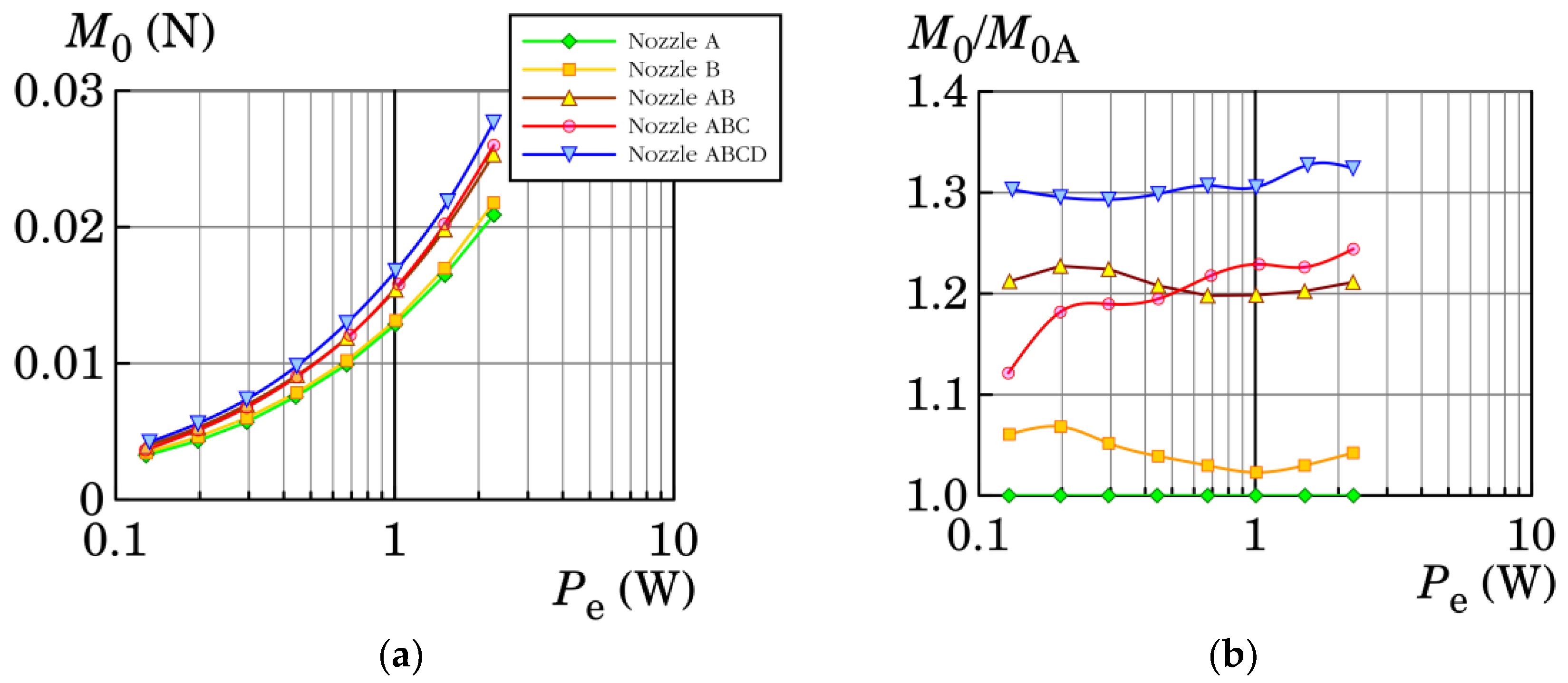
The synthetic jet thrust was measured for each nozzle at several input power levels defined in Table 1. The obtained dependencies of the SJ momentum flux on the input power, Pe, are plotted in Figure 3a. As expected, the curves show monotonically increasing trends. For better comparison of the nozzles, Figure 3b shows relative results with respect to reference nozzle A. With the help of Figure 3b, it can be concluded that the lowest momentum fluxes were achieved using nozzle A and the highest momentum fluxes were achieved with nozzle ABCD. Namely, nozzle ABCD caused a 29–33% enhancement of the momentum flux in comparison with the reference nozzle A. It can be also seen that the resultant momentum fluxes for nozzles A and B were similar, as well as for nozzles AB and ABC. The comparison of the curves in Figure 3b proved that the auxiliary nozzle in the ABCD arrangement was successful in directing the radially dispersed momentum flux. The radial dispersion of the fluid was supposedly caused by the outer nozzle fillet; i.e., nozzle part C.
Apart from that, during the suction stroke, the auxiliary nozzle prevented fluid suction in the axial direction and supported the radial direction. This resulted in a significant increase in the SJ momentum flux.
4.3. Measurement of Velocity Profiles
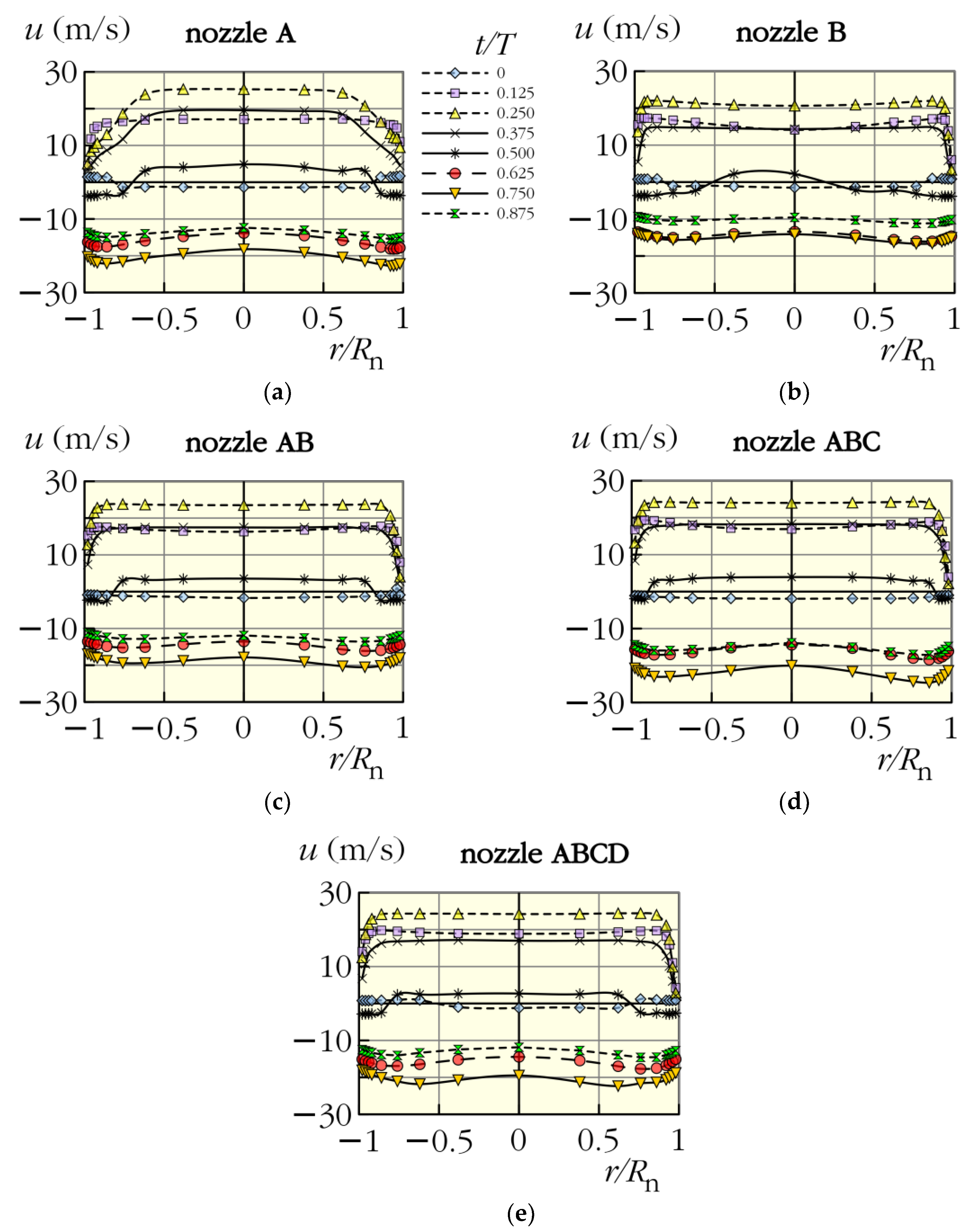
The velocity profiles measured at Pe = 0.68 W and at the optimal (resonant) frequencies, quantified in Figure 2, are shown for the tested nozzles in Figure 4a–e. It is well apparent that the shapes of velocity profiles of the nozzle A (Figure 4a) were markedly different than the profiles of the remaining nozzles. Namely, the boundary layer was much thicker than in the other cases. On the other hand, it was difficult to find a substantial difference in Figure 4b–e. One small difference is apparent for Figure 4b, which plots the results for nozzle B. The velocity profile approaching zero value seems to be slightly asymmetric in this case. This phenomenon can be caused by an unstable and sensitive boundary layer during a beginning of the suction stroke. Namely, a boundary layer separation from the nozzle sharp edge is developed and this effect is promoted by a divergent shape of B nozzle (divergent from the point of view of the suction flow towards the SJA cavity).
Comparing Figure 4c–e, another slight difference is noticeable for nozzle ABCD, where a bit higher velocities were measured than in remaining cases.
4.4. Evaluation of mn and ξ
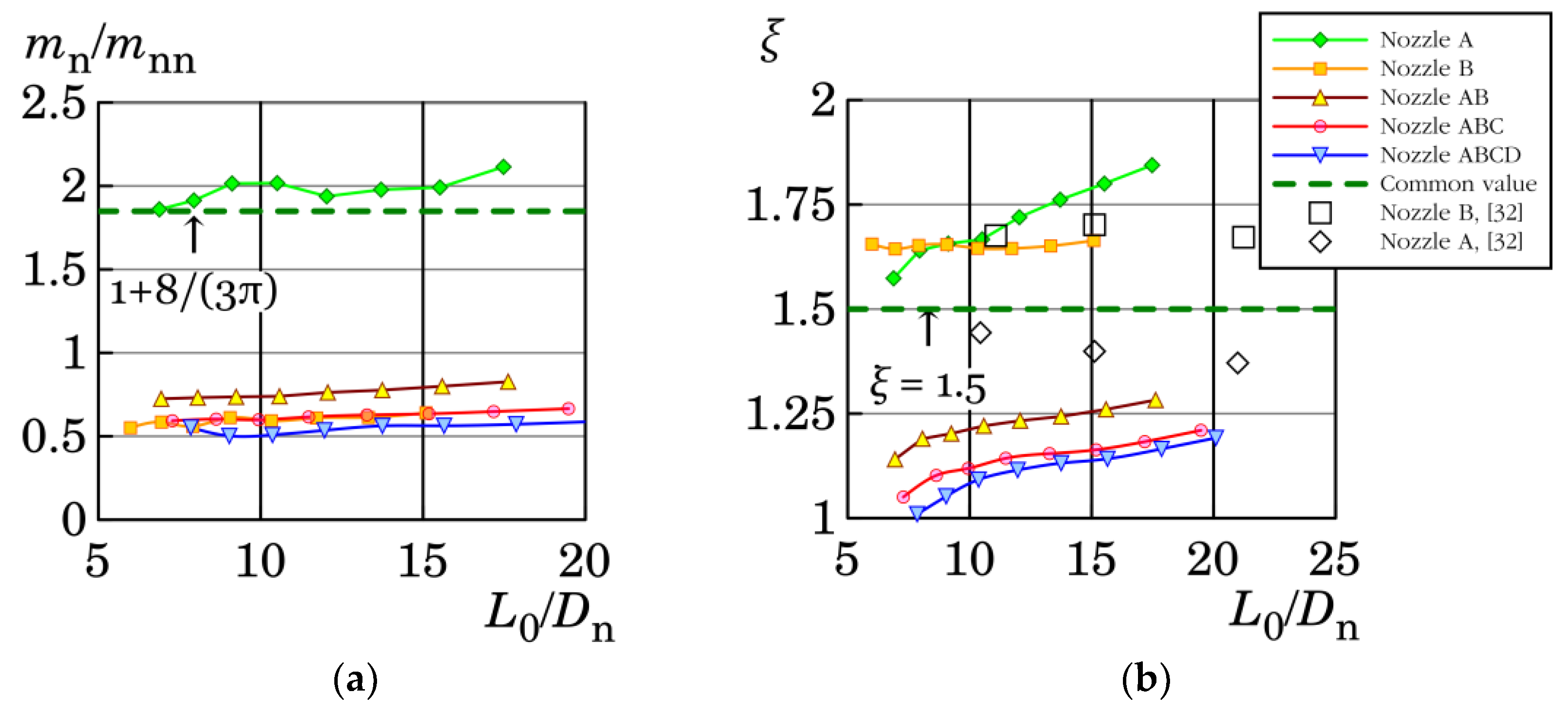
Based on the measurements of cavity pressure variations and spatial integration of velocity profiles, the parameters mn and ξ were evaluated. The evaluation method is summarized in Appendix A and the results are shown in Figure 5a,b. The mass of the moving fluid inside and outside a nozzle, mn, is plotted here in a dimensionless form. Namely, it is related to the mass of air inside the nozzle, mnn. The ratio mn/mnn is shown in Figure 5a as a function of the dimensionless stroke length, L0/Dn, where the stroke length, L0, was evaluated using Equations (1) and (3). The theoretical value of this ratio for a cylindrical hole is displayed with graphs in Figure 5a and this value, 1 + 8/(3π), reasonably agrees with the results for the cylindrical nozzle A. Furthermore, it was found out that relative to their volumes the nozzles (B, AB, ABC, ABCD) employed much less air into the motion than nozzle A and their ratios mn/mnn were very similar. It is also noticeable that all evaluated ratios mn/mnn had a very weak dependence on the dimensionless stroke length, L0/Dn and, therefore, in a first approximation, they can be assumed constant.
The pressure loss coefficients as functions of the dimensionless stroke length, L0/Dn, are displayed in Figure 5b. The results for nozzle A created a slightly increasing curve, which when compared to the results of Nani and Smith [32] showed a 15–27% difference. This could have been caused by several factors including: different evaluation methods—the method in [32] did not include the optimization for mn; different Reynolds number—as was mentioned at the beginning of the paper—the SJ is defined by the dimensionless stroke length and the Reynolds number. While the current Reynolds numbers were in the range of 2400–7100, the results from [32] were obtained at constant Reynolds number of 11,100.
Surprisingly, the evaluated pressure loss coefficients for nozzle B were nearly identical to those found by Nani and Smith [32], as seen in Figure 5b. Apart from that, the pressure loss coefficient for nozzle B appeared to be nearly independent of dimensionless stroke length, L0/Dn. However, this was not true for the remaining cases (AB, ABC, and ABCD), where a slightly increasing trend with a constant rate was well apparent. The lowest pressure loss coefficients ≈ 1.0 were found for the configuration ABCD, at the lowest stroke lengths.
5. Conclusions
Five types of flanged nozzles for a SJA were tested. The first nozzle was a sharp-edged circular hole (nozzle A) and the second had a rounded shape (nozzle B). The third nozzle (AB) was a compound of both previous nozzles—its shape was rounded with a straight section at the nozzle exit. The next nozzle type had a special design with fillets at the inner and outer nozzle exits, with a small sharp step in the middle of the nozzle (case ABC). The last nozzle was assembled as the nozzle ABC but included an auxiliary outer nozzle placed slightly downstream from the nozzle ABC exit (the nozzle is denoted ABCD).
The investigated actuator that was based on a loudspeaker and worked at resonance was tested at several power inputs. The investigation of SJ momentum flux was based on the thrust measurements with a precision scale. It was found out that the highest momentum flux was achieved with original nozzle designs (ABC and ABCD) over the entire power input range. Namely, the nozzle ABCD caused a 29–33% enhancement of the momentum flux in comparison with the reference (common, sharp-edged) nozzle A. The velocity profiles were measured using hot-wire anemometry. The comparison of the velocity profiles revealed that the profiles of nozzles B, AB, ABC, and ABCD had very similar shapes, which differed from case A, where thicker boundary layer was present.
Furthermore, a method for evaluating the moving fluid mass and pressure loss coefficient was introduced. The method was based on known velocity and pressure waveforms and on the momentum equation for fluid inside a nozzle. On the basis of the method, the moving fluid mass and the pressure loss coefficient were observed as functions of dimensionless stroke length. It was revealed that the ratio of the moving fluid mass and the mass of air volume inside the nozzle was nearly independent of the dimensionless stroke length.
Author Contributions
Conceptualization, J.K. and Z.T.; Funding acquisition, Z.T.; Investigation, J.K.; Methodology, J.K.; Project administration, Z.T.; Software, J.K.; Supervision, Z.T.; Visualization, J.K.; Writing—original draft, J.K.; Writing—review & editing, Z.T.
Acknowledgments
We gratefully acknowledge the support of Grant Agency CR (project number 16-16596S) and the institutional support (RVO: 61388998).
Conflicts of Interest
The authors declare no conflict of interest.
Nomenclature
| D | diameter, m |
| e | electrical voltage, V |
| f | driving frequency, Hz |
| g | magnitude of the gravitational acceleration, m/s2 |
| i | electrical current, A |
| L | length, m |
| M | momentum flux, N |
| m | mass, kg |
| p | pressure, Pa |
| P | input power, W |
| r | radial coordinate, m |
| Re | Reynolds number, 1 |
| S | cross-sectional area, m2 |
| T | time period, s |
| t | time, s |
| u | velocity, m/s |
| x | axial coordinate, m |
| ρ | density, kg/m3 |
| Subscripts | |
| 0 | averaging in time and space |
| A | related to the nozzle A |
| b | barometric |
| c | cavity |
| d | diaphragm |
| e | electrical |
| E | extrusion stroke |
| n | nozzle |
| nn | related to nozzle internal |
| Superscripts | |
| * | dimensionless |
Appendix A. Estimation of mn and ξ
The pressure loss coefficient, ξ, and moving fluid mass, mn, were obtained from the least-square-fit on the experimental data, similarly to Persoons [29], or to Persoons and O’Donovan [28], whose method was later used by Nani and Smith [32]. Unlike Persoons [29], who fits the parameters at different SJA driving frequencies, the momentum Equation (4) was used here as the criterion to be satisfied at each time instant of a measured velocity sample. The second difference from the Persoons method was that the current approach is not limited by assumption of harmonic shapes in the velocity and pressure waveform. The third difference was the fact that the nonlinear term of minor losses is not linearized here. These differences make the suggested method slightly more general.
The proposed parameter fitting was based on the momentum equation for fluid motion inside the nozzle only. This is the second equation in Equation (4), which can be rewritten in the following matrix form:
where the overlines above velocities denote spatial averaging. Equation (A1) can be extended for set of velocity, un, and pressure, pc, samples acquired during the driving period as follows:
where velocity , and pressure, pc,i, samples are supplied here with index i, from 1 to m, where m is the number of samples in the measured velocity waveform. The velocity waveform was evaluated from velocity profile integration as follows:
The velocity derivatives, , in Equation (A2) were obtained using numerical derivation of the velocity waveform evaluated from Equation (A3).
The system of Equation (A2) is overdetermined and only an approximate solution can be found. Moore–Penrose matrix inversion allows us to find such solution that corresponds to the least-square-fitting. Hence, the parameters ξ and mn, were solved as follows:
where the index T denotes the operation for matrix transposition and the index −1 denotes the matrix inversion operation.
References
- Smith, B.L.; Glezer, A. The formation and evolution of synthetic jets. Phys. Fluids 1998, 10, 2281–2297. [Google Scholar] [CrossRef]
- Cater, J.E.; Soria, J. The evolution of round zero-net-mass-flux jets. J. Fluid Mech. 2002, 472, 167–200. [Google Scholar] [CrossRef]
- Lardeau, S.; Leschziner, M.A. The interaction of round synthetic jets with a turbulent boundary layer separating from a rounded ramp. J. Fluid Mech. 2011, 683, 172–211. [Google Scholar] [CrossRef] [Green Version]
- Bernardini, C.; Carnevale, M.; Manna, M.; Martelli, F.; Simoni, D.; Zunino, P. Turbine blade boundary layer separation suppression via synthetic jet: An experimental and numerical study. J. Therm. Sci. 2012, 21, 404–412. [Google Scholar] [CrossRef]
- Jabbal, M.; Zhong, S. Particle image velocimetry measurements of the interaction of synthetic jets with a zero-pressure gradient laminar boundary layer. Phys. Fluids 2010, 22, 063603. [Google Scholar] [CrossRef] [Green Version]
- Sahni, O.; Wood, J.; Jansen, K.E.; Amitay, M. Three-dimensional interactions between a finite-span synthetic jet, a crossflow. J. Fluid Mech. 2011, 671, 254–287. [Google Scholar] [CrossRef]
- Xia, X.; Mohseni, K. Transitional region of a round synthetic jet. Phys. Rev. Fluids 2018, 3, 011901. [Google Scholar] [CrossRef]
- Chiatto, M.; Capuano, F.; de Luca, L. Numerical and experimental characterization of a double-orifice synthetic jet actuator. Meccanica 2018, 53, 2883–2896. [Google Scholar] [CrossRef]
- Seo, J.H.; Cadieux, F.; Mittal, R.; Deem, E.; Cattafesta, L. Effect of synthetic jet modulation schemes on the reduction of a laminar separation bubble. Phys. Rev. Fluids 2018, 3, 033901. [Google Scholar] [CrossRef]
- Xia, Z.-X.; Luo, Z.-B. Physical factors of primary jet vectoring control using synthetic jet actuators. Appl. Math. Mech. 2007, 28, 907–920. [Google Scholar] [CrossRef]
- Ben Chiekh, M.; Ferchichi, M.; Béra, J.-C.C. Aerodynamic flow vectoring of a wake using asymmetric synthetic jet actuation. Exp. Fluids 2012, 53, 1797–1813. [Google Scholar] [CrossRef]
- Trávníček, Z.; Němcová, L.; Kordík, J.; Tesař, V.; Kopecký, V. Axisymmetric impinging jet excited by a synthetic jet system. Int. J. Heat Mass Transf. 2012, 55, 1279–1290. [Google Scholar] [CrossRef]
- McGuinn, A.; Farrelly, R.; Persoons, T.; Murray, D.B. Flow regime characterisation of an impinging axisymmetric synthetic jet. Exp. Therm. Fluid Sci. 2013, 47, 241–251. [Google Scholar] [CrossRef] [Green Version]
- Lee, A.; Yeoh, G.H.; Timchenko, V.; Reizes, J.A. Heat transfer enhancement in micro-channel with multiple synthetic jets. Appl. Therm. Eng. 2012, 48, 275–288. [Google Scholar] [CrossRef]
- Zhang, Y.; Li, P.; Xie, Y. Numerical investigation of heat transfer characteristics of impinging synthetic jets with different waveforms. Int. J. Heat Mass Transf. 2018, 125, 1017–1027. [Google Scholar] [CrossRef]
- Trávníček, Z.; Vít, T.; Tesař, V. Hybrid synthetic jets as the nonzero-net-mass-flux synthetic jets. Phys. Fluids 2006, 18, 081701. [Google Scholar] [CrossRef]
- Trávníček, Z.; Tesař, V.; Kordík, J. Performance of synthetic jet actuators based on hybrid and double-acting principles. J. Vis. 2008, 11, 221–229. [Google Scholar] [CrossRef]
- Kordík, J.; Trávníček, Z. Novel fluidic diode for hybrid synthetic jet actuator. J. Fluids Eng. 2013, 135, 101101. [Google Scholar] [CrossRef]
- Kordík, J.; Broučková, Z.; Trávníček, Z. Impinging jet-based fluidic diodes for hybrid synthetic jet actuators. J. Vis. 2015, 18, 449–458. [Google Scholar] [CrossRef]
- Gallas, Q.; Holman, R.; Nishida, T.; Carroll, B.; Sheplak, M.; Cattafesta, L. Lumped element modeling of piezoelectric-driven synthetic jet actuators. AIAA J. 2003, 41, 240–247. [Google Scholar] [CrossRef]
- Kim, B.H.; Williams, D.R.; Emo, S.; Acharya, M. Modeling pulsed-blowing systems for flow control. AIAA J. 2005, 43, 314–325. [Google Scholar] [CrossRef]
- Kordík, J.; Trávníček, Z. Axisymmetric synthetic jet actuators with large streamwise dimensions. AIAA J. 2013, 51, 2862–2877. [Google Scholar] [CrossRef]
- De Luca, L.; Girfoglio, M.; Coppola, G. Modeling and experimental validation of the frequency response of synthetic jet actuators. AIAA J. 2014, 52, 1733–1748. [Google Scholar] [CrossRef]
- Sharma, R.N. Fluid-dynamic-based analytical model for synthetic jet actuation. AIAA J. 2007, 45, 1841–1847. [Google Scholar] [CrossRef]
- Chiatto, M.; Capuano, F.; Coppola, G.; de Luca, L. LEM characterization of synthetic jet actuators driven by piezoelectric element: A review. Sensors 2017, 17, 1216. [Google Scholar] [CrossRef] [PubMed]
- Broučková, Z.; Trávníček, Z. Visualization study of hybrid synthetic jets. J. Vis. 2015, 18, 581–593. [Google Scholar] [CrossRef]
- Mohseni, K.; Mittal, R. Synthetic Jets: Fundamentals and Applications; CRC Press, Taylor & Francis: Boca Raton, FL, USA, 2015. [Google Scholar]
- Persoons, T.; O’Donovan, T.S. A pressure-based estimate of synthetic jet velocity. Phys. Fluids 2007, 19, 128104. [Google Scholar] [CrossRef] [Green Version]
- Persoons, T. General reduced-order model to design and operate synthetic jet actuators. AIAA J. 2012, 50, 916–927. [Google Scholar] [CrossRef]
- Kordík, J.; Trávníček, Z. Optimal diameter of nozzles of synthetic jet actuators based on electrodynamic transducers. Exp. Therm. Fluid Sci. 2017, 86, 281–294. [Google Scholar] [CrossRef]
- Kordík, J.; Broučková, Z.; Vít, T.; Pavelka, M.; Trávníček, Z. Novel methods for evaluation of the Reynolds number of synthetic jets. Exp. Fluids 2014, 55, 1757. [Google Scholar] [CrossRef]
- Nani, D.J.; Smith, B.L. Effect of orifice inner lip radius on synthetic jet efficiency. Phys. Fluids 2012, 24, 115110. [Google Scholar] [CrossRef]
- Kordík, J.; Trávníček, Z.; Timchenko, V.; Ismail, N.A. The predominant effect of stroke length on velocity profiles at the exit of axisymmetric synthetic jet actuators. Int. J. Heat Fluid Flow 2017, 66, 197–208. [Google Scholar] [CrossRef]
- Tesař, V.; Kordík, J. Quasi-similarity model of synthetic jets. Sens. Actuators A Phys. 2009, 149, 255–265. [Google Scholar] [CrossRef]
- Tesař, V.; Kordík, J. Time-mean structure of axisymmetric synthetic jets. Sens. Actuators A Phys. 2010, 161, 217–224. [Google Scholar] [CrossRef]
- Lee, C.Y.; Goldstein, D.B. Two-dimensional synthetic jet simulation. AIAA J. 2002, 40, 510–516. [Google Scholar] [CrossRef]
- Rylatt, D.I.; O’Donovan, T.S. Heat transfer enhancement to a confined impinging synthetic air jet. Appl. Therm. Eng. 2013, 51, 468–475. [Google Scholar] [CrossRef] [Green Version]
- Kordík, J.; Trávníček, Z. Non-harmonic excitation of synthetic jet actuators based on electrodynamic transducers. Int. J. Heat Fluid Flow 2018, 73, 154–162. [Google Scholar] [CrossRef]
- Trávníček, Z.; Fedorchenko, A.I.; Wang, A.-B. Enhancement of synthetic jets by means of an integrated valve-less pump, Part I: Design of the actuator. Sens. Actuator A Phys. 2005, 120, 232–240. [Google Scholar] [CrossRef]
- Kooijman, G.; Ouweltjes, O. Finite difference time domain electroacoustic model for synthetic jet actuators including nonlinear flow resistance. J. Acoust. Soc. Am. 2009, 125, 1911–1918. [Google Scholar] [CrossRef] [PubMed]
- Trávníček, Z.; Broučková, Z. A synthetic jet issuing from a bio-inspired actuator with an oscillating nozzle lip. J. Fluids Eng. 2018, 140, 101104. [Google Scholar] [CrossRef]
- Kordík, J.; Trávníček, Z. Integral quantities of axisymmetric synthetic jets evaluated from a direct jet thrust measurement. Flow Turbul. Combust. 2018. submitted. [Google Scholar]
- Kordík, J. Theoretical and Experimental Analysis of Synthetic and Hybrid Synthetic Jet Actuators. Ph.D. Thesis, Czech Technical University, Prague, Czech Republic, 2011. [Google Scholar]
Figure 1.
Experimental setup and methods (dimensions in millimeters): (a) synthetic jet actuator with nozzle ABCD mounted, (b) shapes of the tested nozzles.
Figure 1.
Experimental setup and methods (dimensions in millimeters): (a) synthetic jet actuator with nozzle ABCD mounted, (b) shapes of the tested nozzles.

Figure 2.
Frequency characteristics of SJA measured at 1.0 W. The local maxima indicate the resonance frequencies for all particular nozzle cases; they are also summarized in Table 2.
Figure 2.
Frequency characteristics of SJA measured at 1.0 W. The local maxima indicate the resonance frequencies for all particular nozzle cases; they are also summarized in Table 2.

Figure 3.
Results for experiments with precision scales performed at eight input power levels: (a) evaluated SJ thrust, (b) SJ thrust divided by the jet thrust values of the reference case—nozzle A.
Figure 3.
Results for experiments with precision scales performed at eight input power levels: (a) evaluated SJ thrust, (b) SJ thrust divided by the jet thrust values of the reference case—nozzle A.

Figure 4.
Velocity profiles measured by the hot-wire probe at the nozzle exits at input power of 0.68 W and the optimal (resonant) frequencies quantified in Figure 2.
Figure 4.
Velocity profiles measured by the hot-wire probe at the nozzle exits at input power of 0.68 W and the optimal (resonant) frequencies quantified in Figure 2.

Figure 5.
Evaluated parameters for lumped parameter model: (a) mass of the moving fluid inside the nozzle related to the fluid mass inside a nozzle, (b) pressure loss coefficient at cavity-nozzle-ambiance transition.
Figure 5.
Evaluated parameters for lumped parameter model: (a) mass of the moving fluid inside the nozzle related to the fluid mass inside a nozzle, (b) pressure loss coefficient at cavity-nozzle-ambiance transition.


Table 1.
Basic properties of the used synthetic jet actuator (SJA), fluid properties and forcing details.
Table 1.
Basic properties of the used synthetic jet actuator (SJA), fluid properties and forcing details.
| Quantity | Symbol | Value | Unit |
|---|---|---|---|
| Synthetic jet actuator | |||
| Loudspeaker type | Aurasound NS3-193-8A | ||
| Nozzle diameter | Dn | 10.0 | (mm) |
| Diaphragm effective diameter | Dd | 60.8 | (mm) |
| Mass of air inside the nozzle volume | mnn | 0.92, 2.1, 3.0, 3.5, 4.1 | (mg) |
| Fluid: air | |||
| Ambient temperature | Ta | 24.2–26.6 | (°C) |
| Barometric pressure | pb | 98 000–98 900 | (Pa) |
| Density | ρ | 1.14–1.15 | (kg/m3) |
| Forcing | |||
| Input real power | Pe | 0.13, 0.20, 0.30, 0.45, 0.68, 1.02, 1.53, and 2.30 | (W) |
| Actuating frequency | f | 55–65 | (Hz) |
Table 2.
Identified resonance frequencies for particular nozzle cases.
| Nozzle A | 55 Hz |
| Nozzle B | 65 Hz |
| Nozzle AB | 60 Hz |
| Nozzle ABC | 55 Hz |
| Nozzle ABCD | 55 Hz |
© 2018 by the authors. Licensee MDPI, Basel, Switzerland. This article is an open access article distributed under the terms and conditions of the Creative Commons Attribution (CC BY) license (http://creativecommons.org/licenses/by/4.0/).
Share and Cite
MDPI and ACS Style
Kordík, J.; Trávníček, Z. Novel Nozzle Shapes for Synthetic Jet Actuators Intended to Enhance Jet Momentum Flux. Actuators 2018, 7, 53. https://doi.org/10.3390/act7030053
AMA Style
Kordík J, Trávníček Z. Novel Nozzle Shapes for Synthetic Jet Actuators Intended to Enhance Jet Momentum Flux. Actuators. 2018; 7(3):53. https://doi.org/10.3390/act7030053
Chicago/Turabian StyleKordík, Jozef, and Zdeněk Trávníček. 2018. "Novel Nozzle Shapes for Synthetic Jet Actuators Intended to Enhance Jet Momentum Flux" Actuators 7, no. 3: 53. https://doi.org/10.3390/act7030053
Note that from the first issue of 2016, this journal uses article numbers instead of page numbers. See further details here.