1. Introduction
Research focused on rehabilitation and gait assistance has grown rapidly in recent years. Novel designs take into account the state of the art in artificial muscles as well as a good understanding of the biomechanics and performance of biological structures. They try to emulate the natural behavior of natural muscles in many cases, while others evaluate and take advantage of their attributes in order to improve some qualities of the actuation system. Incorporating intrinsic compliance with traditional actuators is one of the strategies used to compensate for some of the drawbacks that come with conventional electric actuator and gear-motor implementation [
1]: poor torque density, high stiffness, low force to weight ratio, high reflected inertia and lack of compliance (non-adaptability). Series elastic actuators (SEAs) are inherently compliant by introducing an elastic element between the actuator and the load [
1,
2]. They present several unique properties compared to rigid actuators, including low mechanical output impedance, tolerance of impact loads, increased peak power output, and passive mechanical energy storage under certain conditions [
3]. New devices try to overcome the bandwidth limitation and improve the performance of SEAs by incorporating an extra (softer) elastic element in the transmission train. These actuators, such as the compact SEA [
4], the high-performance SEA [
5], and the Compat Rotary SEA (cRSEA) [
3], improve the force-control performance under a wider range of forces/torques at the device joints when compared to traditional SEAs, although the energy storage capability will still depend on the resulting fixed springs constants; thus, a proper selection of the elastic constant based on the application, intended user and control strategy needs to be performed [
4].
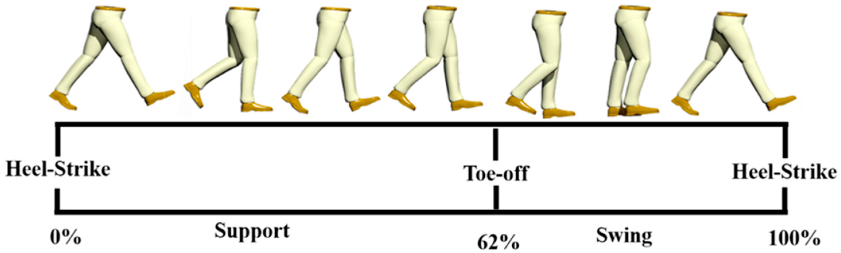
Level-ground walking is typically defined as beginning with the heel strike of one foot and ending at the next heel strike of the same foot [
6]. Walking kinematics can slightly vary between subjects, nevertheless the gait cycle can be divided into the support phase—where the leg accommodates to the ground and body weight—and the swing phase, when the foot is off the ground after toe-off (see
Figure 1). Along the locomotion cycle there is evidence of impedance variation, whereas leg joints perform positive as well as negative work. If the energy dissipated due to the negative work is stored, transferred and reused, a more efficient gait cycle is possible [
7]. To be able to fully exploit the natural dynamics of the legs during walking, a combination of energy storage and controllable adaptable compliance is needed [
8].
Variable impedance actuators (VIA) can adapt their compliant properties typically by means of a second motor that modulates the stiffness of the device. Incorporating these actuators in exoskeleton joints could result in a significant number of advantages in terms of control, adaptability, safety and energy efficiency. Based on the VIACTORS [
9] classification and a previous publication [
10], spring preload actuators, such as the VS-joint [
11] and the QA-Joint [
12] from the German Aerospace Center (DLR, can exert the high torques required of the exoskeleton joints and adapt their compliance at an acceptable speed. The MACCEPA 2.0 [
13] from Vrije Universiteit Brussel (VUB) has been incorporated into the rehabilitation device ALTACRO) [
14]. The mechanism can take advantage of the elastic element to calculate a torque measure at the joint without the need for an external torque sensor. However, the stiffness regulation of these devices is achieved by acting directly over the springs; thus, the compliance adaptation requires a large motor or gearbox to overcome the spring forces, or the adjustment time is too slow for online adjustments during gait. On the other hand, many of the designs from the Italian Institute of Technology (IIT), such as the AWAS [
15], AWAS-II [
16], CompAct [
17] and VSAUT-II [
18] to name a few, achieve compliance adaptation by changing the transmission between the load and the spring. The main feature of this group is that the size of the actuator responsible for the stiffness regulation can significantly be reduced because it only has to overcome friction, and a percentage of the spring actions in the presence of external loads at the joint. Although these actuators attempt to present a compact configuration, the torque sensor and the compliance mechanism in series results in devices with large dimensions and weight able to be implemented in exoskeleton joints, especially when children are the intended users. In a previous work, an actuator with an adjustable rigidity and embedded force sensor (ARES) [
19] was presented. Its stiffness adjustment is also achieved by changing the transmission between the load and the spring. It was characterized by reutilizing the compliant elements that provide elasticity to the joint, allowing the measurement of the torque exerted by the joint, and avoiding a bulky arrangement that could protrude considerably from the exoskeleton.
The main drawback of SEAs and current VIAs is that the springs incorporated in their mechanism are a source of non-controllable energy buffers [
20]. The incorporation of clutches and locking devices in joint actuation systems has become a popular way to control the energy flow in springs [
21]. A clutch/locking device switches between allowing and preventing relative motion among two parts; several properties and characteristics, presented in [
20], are desirable in these devices when implemented for prosthetics and exoskeleton applications.
Energy management and reconfiguration of the system are some of the main reason for the implementation of clutches. These devices are incorporated in several powered prosthetics in order to improve their energy efficiency, such as the AMP-Foot 3.0 [
22], allowing this ankle prosthetic to change its elastic behavior along gait, while preloading a spring from which energy is released at the push-off at the end of the support phase. The Clutchable SEA [
23], and the CPEA [
24], are examples of clutches implemented in knee prosthetics in order to decouple the elastic components, in series and parallel respectively, during phases of the gait where their action is not required or beneficial. The BIC-PEA [
25,
26] is a prototype actuator comprising two locking mechanisms and a differential gear. By contrast with typical parallel elastic actuators (PEAs), the BIC-PEA is capable of holding the energy stored at the spring and released in the desired direction. The drawback of these devices resides in the incorporation of fixed springs, similar to common SEAs, and a proper selection is required based on the task and intended users.
The sVSA [
27] is a variable stiffness actuator that implements a clutch to switch between position and stiffness control by means of a single main motor. The prototype intents to reduce the size associated with VIAs due to the second motor, normally used for stiffness regulation, however this action occurs at low speed and is not adequate for online applications where the adjustments need to be done quickly, and the release of energy stored at the elastic elements cannot be controlled.
The ARES-XL is a new VIA that by presenting a double-bar linkage, its deflection and stiffness capabilities provide it with wide versatility for incorporation in different joints, and for multiple applications. An added novelty of this device is the possibility of implementing a locking mechanism to lock the deflection achieved in certain phases of the locomotion cycle, in order to take advantage of that stored energy and release it in a non-consecutive phase.
This paper is organized as follows: a complete description of the ARES-XL is given in the Materials and Methods section. In this section the mechanics of the system as well as its novel locking property are discussed. An assessment of the joint, including torque-measuring capabilities and the versatility of the joint, are presented in the results section. Finally, general conclusions and future work are given.
2. Materials and Methods
In this section, we present our novel actuator ARES-XL. The mechanism design is described, and the novel implementation of a locking mechanism characterized by its simplicity presented. Finally, the developed VIA is installed in the bench test and the experimental setup is described.
2.1. Adjustable Rigidity with Embedded Sensor and Locking Mechanism Actuator (ARES-XL) Design
Focused on the actuation of the ATLAS lower-limb active orthosis, we presented in a previous work the ARES [
19,
28], a VIA whose characteristics and arrangement along the mechanical structure of the exoskeleton made it an interesting option to be incorporated in a pediatric device [
29]. However, there were several limitations associated with the actuator prototype; such as: the inability to achieve zero stiffness, the limited range of deflection allowed at the joint, and the lack of control in the timing to release the energy stored at the joint.
The ARES-XL, a new adjustable rigidity with embedded sensor and locking mechanism actuator, is a novel VIA whose capabilities exceed those achieved with the ARES actuator and other SoA devices. Obviously, ARES is its predecessor; nevertheless, the new prototype is not just a redesign. The authors have improved its mechanics, added functionality, present a new configuration, and have included a simple but advantageous new locking mechanism to the system as an add-on.
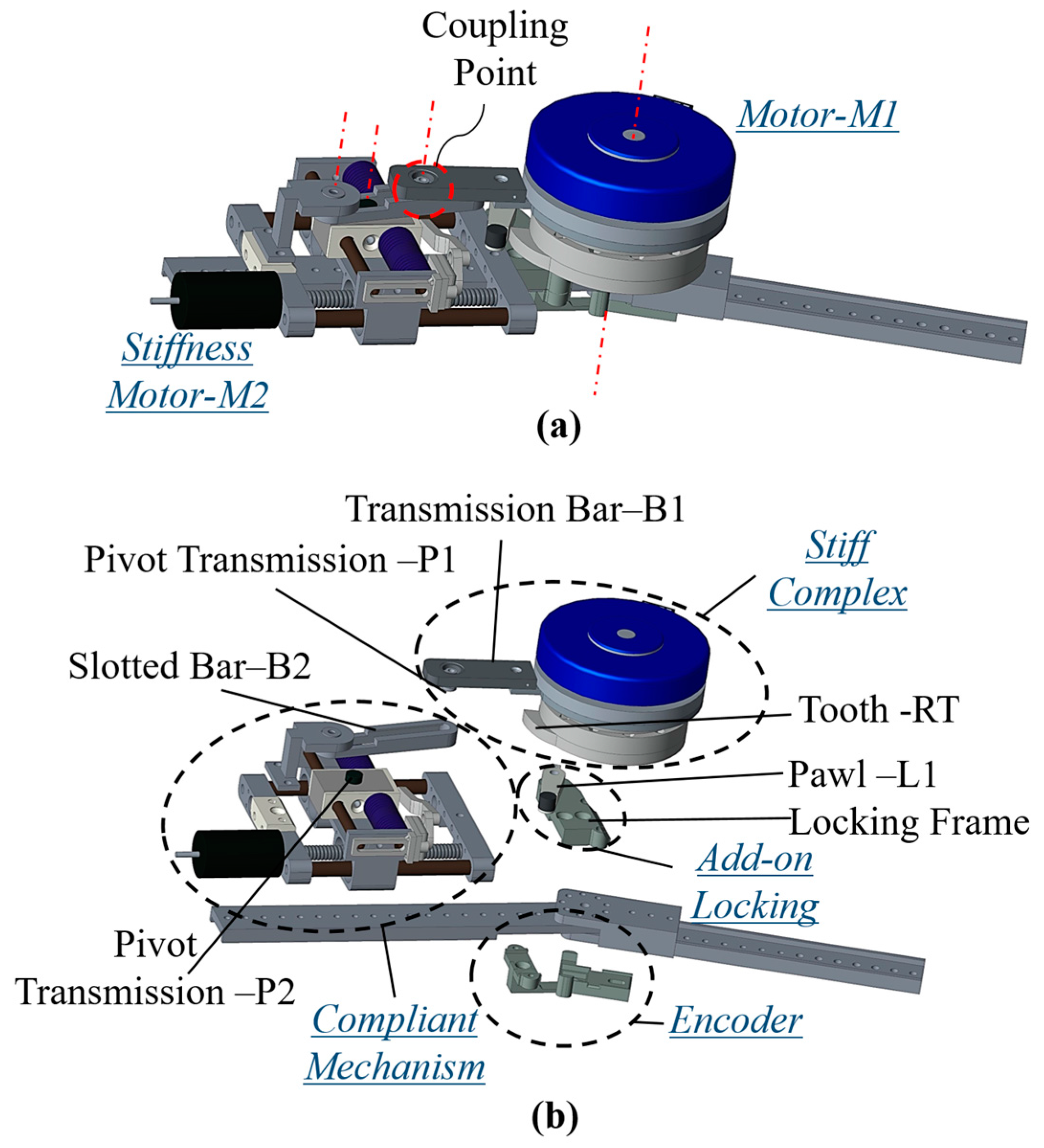
ARES-XL is intended to be implemented in several joints of the robotic device, and its equilibrium position and compliance are independently controlled. The torque control of the device together with the maintenance of a reduced lateral size are the main goals for this design presented in
Figure 2a. The current prototype maintains the general dimension of the ARES actuator of 70 mm width and 260 mm length, weighs nearly 1.2 kg, making it suitable to be incorporated in the links of powered exoskeletons aimed for children. By including an add-on in the mechanism, the release of energy stored at the joint, under certain conditions, can be controlled, giving ARES-XL properties that, to the best of our knowledge, are beyond those of the current SoA in VIAs. The mechanics of the actuator are presented below together with its working principles, torque-sensing properties and locking capabilities.
2.1.1. Joint Mechanics
A computer-aided design (CAD) representation of the ARES-XL with its main components in an exploded view is shown in
Figure 2b. This VIA is primarily formed by the compliant mechanism responsible for setting joint stiffness, and a stiff complex that generates the main power required at the joint. These two components are arranged along the structure to reduce the lateral size of the mechanism, which from previous works should not exceed 70 mm [
19]. The coupling of the main components is achieved by means of a two-bar linkage at the coupling point, indicated in
Figure 2a, connected to the compliant mechanism. The coupling presented in ARES-XL represents a significant distinction to other VIAs and the previous ARES prototype. A locking mechanism (add-on) can be implemented in the ARES-XL to lock a particular joint deflection or to store the elastic energy for later use according to the joint requirements and implemented gait.
2.1.2. Stiff Complex
The stiff complex presents a traditional combination of a stiff actuator and a gearbox. The required high torque/size ratio during the locomotion cycle and the required torque/weight ratio in this application—from 30–60 Nm and below 1.2 kg [
19]—are achieved by implementing a flat Maxon motor in combination with the harmonic drive unit. The motor (see
Figure 2) and the harmonic drive combination, denoted as
M1, control the position where the actuator generates zero torque, also known as the equilibrium position of the joint, measured with a rotary encoder (see
Figure 2b).
M1 integrated with the transmission bar
B1 and the pivot
P1 conform the stiff complex. The motor/gearbox combo were selected because of its reduced length and high torque, which makes it very suitable for exoskeletons and active orthosis applications. The nominal outputs of the stiff complex can go up to 2.5 rad/s and 30 nm, which is enough to achieve the requirements during the locomotion cycle in level ground at low speeds (<0.8 m/s) [
30] but with some limitations at the swing and push-off, associated with velocity rates faster than those achievable by traditional electrical motors.
The mechanical structure of the stiff complex incorporates a tooth RT at a certain angle attached to the output of the complex. This element is intended to implement the locking properties of the actuator.
2.1.3. Compliant Mechanism
This mechanism controls the amount of compliance at the joint. A set of elastic elements is placed in a slider system that is connected to a non-backdriveable spindle drive to adjust the slider position along the linear guides of a fixed frame, see
Figure 2b. A motor
M2 connected to the spindle drive, considerably smaller than the main motor
M1, exerts the required force to adjust the slider position when commanded. The slotted bar
B2 pivots over the fixed structure of the compliant mechanism, and transmits the force from the joint to the elastic elements by the contact of the
B2 inner face and the pivot
P2.
The pivot P1 at the end of the transmission bar B1 transfers the torque from the stiff complex to the inner face of the slotted bar B2. This point of contact is defined as the coupling point between the compliant mechanism and the stiff complex. This double-bar linkage provides the new VIA, ARES-XL, with a significant range of stiffness and compliance while maintaining a compact design.
2.1.4. Locking Mechanism—Add-On
To take advantage of the joint elastic deflection in sections of the gait that are not directly connected, the ability to lock the position of the elastic elements in the compliant mechanism is useful. The ARES-XL is a VIA that can incorporate an add-on device into the actuator structure that will lock the deflection position while still being able to modify the output joint position.
Figure 2b shows the device used to achieve the mechanical lock. The device can be categorized as a ratchet [
20] and is comprised of a round structure with a tooth
RT and a pawl
L1 that engages with the tooth
RT, from the stiff complex, and allows locking.
2.2. Working Principle
This new actuator can be classified, based on the work of the VIACTORS consortium [
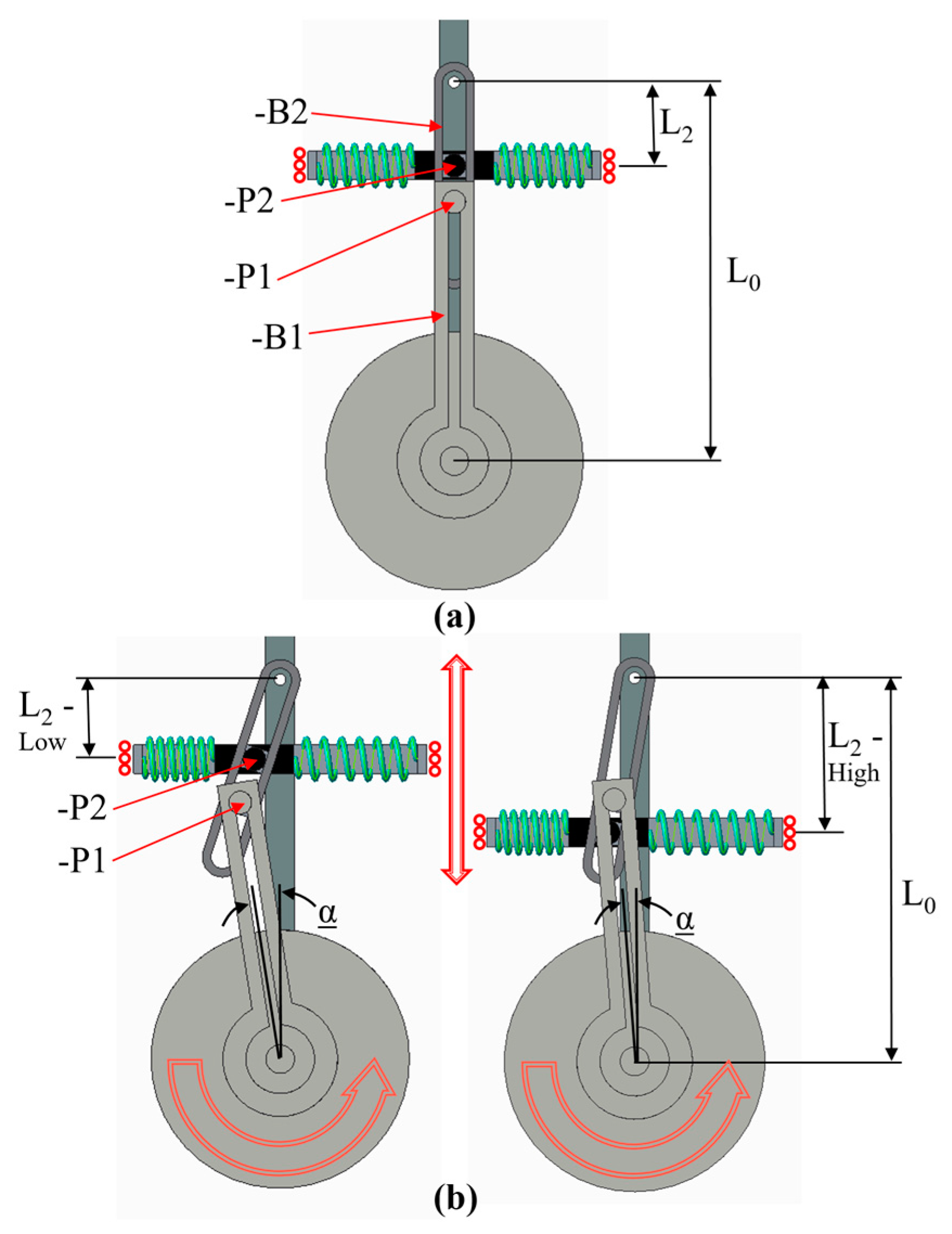
10], as an actuator with a controllable transmission ratio. A double-bar system is formed by the slotted bar
B2 and the transmission bar
B1, see
Figure 3. The torques exerted at the joint are transmitted through the pivot transmission
P1 to the inner face of the slotted bar
B2. The reaction force is transmitted through the slotted bar to the pivot
P2 in contact with the elastic elements in the compliant mechanism. The force in the coupling point is related to the torque at the joint and the constant length of the bar
B1.
Figure 3b shows that in the presence of torque at the joint, the force transmitted through
P1 is opposed by the elastic elements in contact between the slotted bar
B2 and the pivot
P2. The distance L
2 is directly related to the amount of compression in the elastic elements; thus, the stiffness of the joint, and the energy stored in them at a given torque, reach equilibrium. The distance L
2 between the pivot axis of the slotted bar
B2 and the slider system containing the elastic elements is related to the amount of deflection α experienced at the joint system at given exerted torque. If the distance L
2 is large-stiffer configuration; a smaller deflection α is experienced at the joint for a given torque. For L
2 near 0, the compliant mechanism does not oppose resistance to the transmitted force, giving a stiffness in that configuration of zero or close to zero. By controlling the position of the slider system with the use of the motor
M2 in the compliant system, a variation of the output stiffness can be achieved, with the capability of achieving zero stiffness.
The controllable transmission ratio maintains low the power necessary for the variation of the arm length L2 even during online adjustments. The force produced by the motor M2 does not act directly on the springs, which allows a smaller motor to set the position L2. The pivots P1 and P2 can slightly roll inside the slotted bar. The system prevents bending of the elastic elements, and the force is directly transmitted to the fixed frame by the linear guides. These, in combination with the transmission ratio principle, release the motor M2 and the spindle from high loads that can require oversizing of the mechanical components.
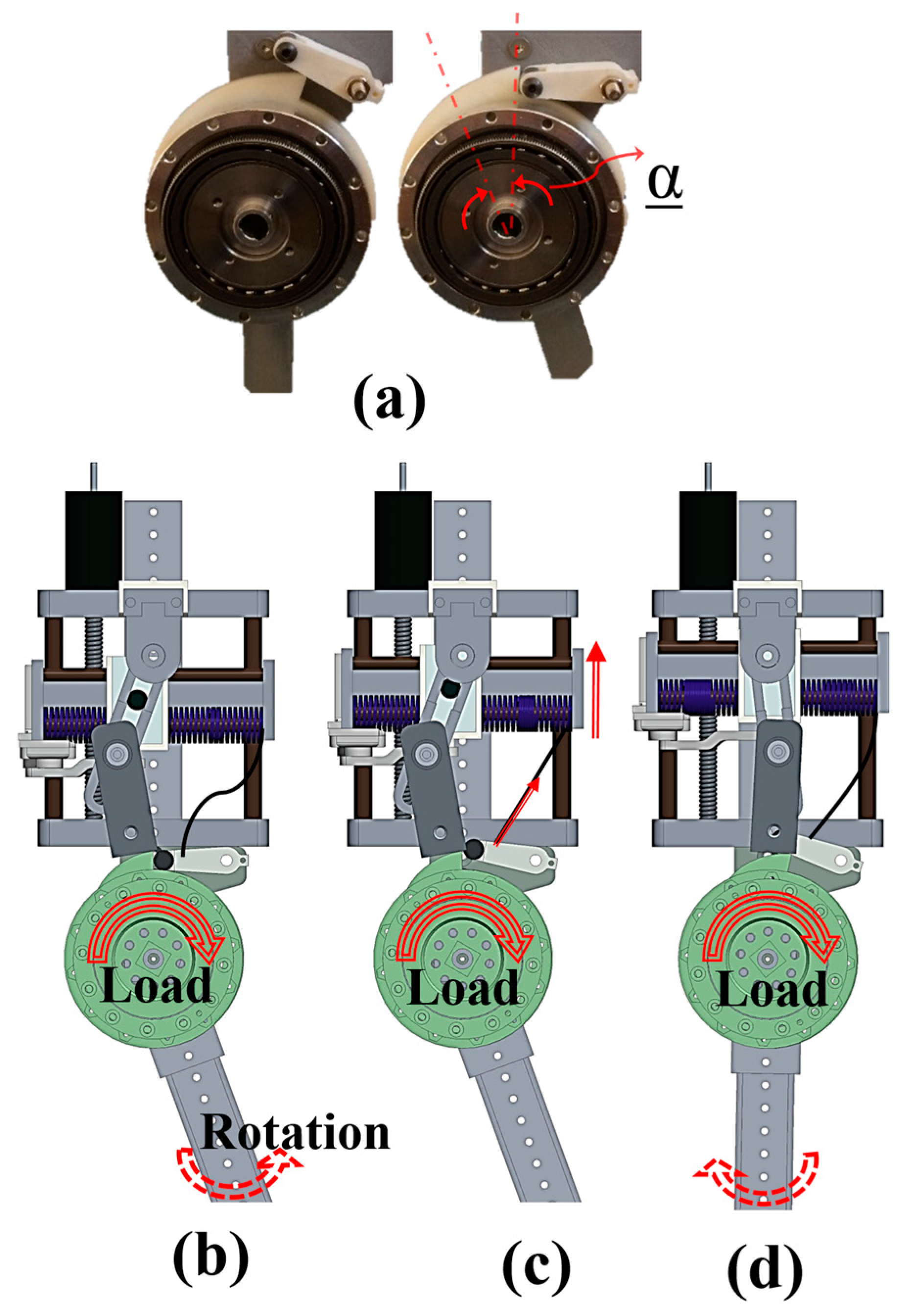
2.3. Locking Principle
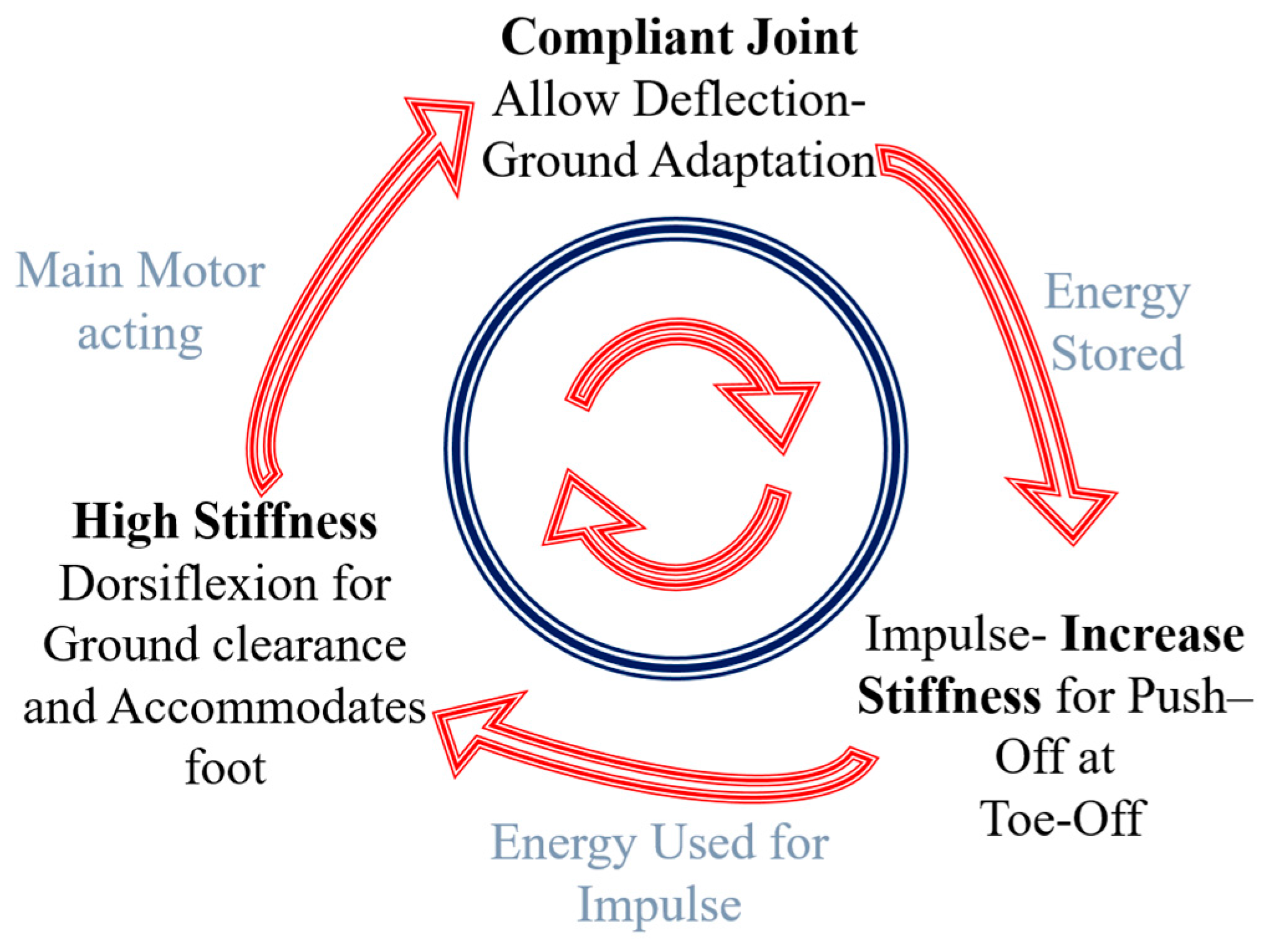
The main purpose of the locking mechanism is to provide ARES-XL with the capability to control the energy stored in the compliant mechanism, particularly for its incorporation in a knee joint. Based on previous works [
8,
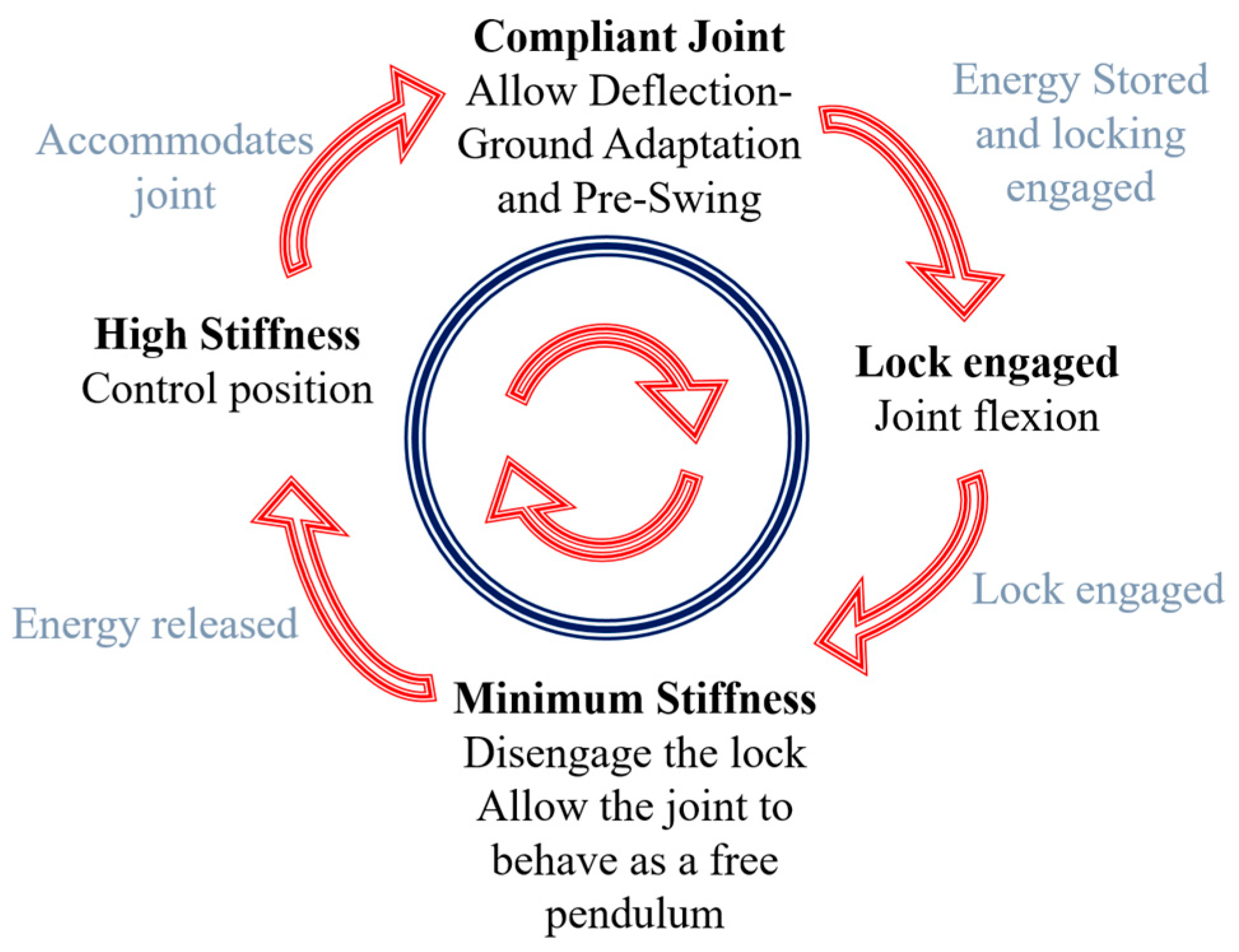
19], the knee can be observed as a passive joint early in the support phase
Figure 1, with a rotational elastic element opposing the body load. Compliant joints can mimic this behavior. However, at the end of the support phase the joint torque changes direction while maintaining the direction of rotation. Any energy stored in the joint will be wasted and could even oppose the motion. Some devices, such as the C-SEA [
23], include a clutch in order to switch from compliant behavior to a variable damper that dissipates this energy. By implementing the add-on locking mechanism in the ARES-XL at the end of the support phase, the lock is passively engaged if the deflection is higher than a fixed value, approximately 10–15 degrees
Figure 4a. The angle of the locking mechanism was selected to guarantee its engagement at the pre-swing from multiple subjects, as this value varies from person to person. With this add-on, energy is not wasted or dissipated but harvested for future re-utilization once the lock is engaged, after the push off the knee continues to flex while loaded in the opposite direction of rotation, see
Figure 4b. The main motor will deliver the power required to move the joint that is not supporting the body weight during the swing phase, facilitating ground clearance.
Figure 4c,d presents the sequence where the lock is disengaged at the end of the swing. The slider from the compliant mechanism will unlock the joint by decreasing joint stiffness and pulling the pawl
L1 under a moderate load. Once disengaged and with low stiffness, (d) the weight at the link, the energy stored, and the deflection will cause the joint to swing freely without the need for the main motor to act.
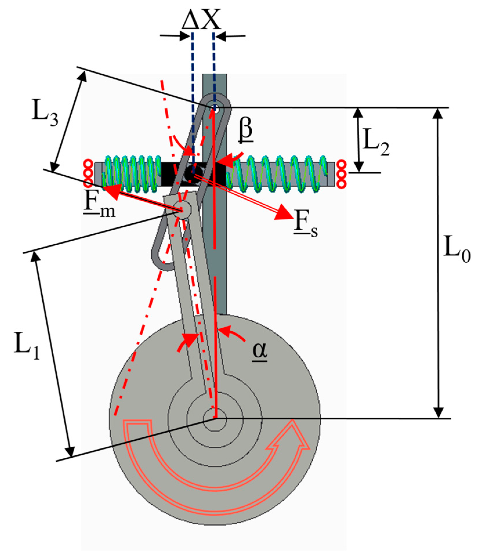
2.4. Force Sensor
The force sensor in the ARES-XL is embedded in the mechanism. The elastic elements are used simultaneously to give compliance to the joint as well as to acquire the torque measurements without adding extra bulky elements, such as a torque sensor. The system uses a magnetic encoder to measure the linear displacement of the elastic elements. The compression, ΔX, in combination with the geometry and mechanical characteristics of the system allow the torque measurement to be computed during operation.
Based on
Figure 5, the relationship for the torque measurement as a function of L
2 and the compression, ΔX can be obtained. The distances L
0 and L
1 are fixed values—of ~132mm and 90mm for this particular prototype—that can affect the size of the system, the range of the stiffness and the maximum deflection, α, allowed at the joint.
The projection of the force transmitted by the motor,
Fm, is perpendicular to the slotted bar
B2, as shown in
Figure 5. With the known and measured values, L
1, L
2, L
3 and
, the rest of the variables can be obtained.
The contact of the inner face of the slotted bar
B2 with the pivot
P1 is always tangent. The force due to the elastic elements,
Fs, transmitted through the slotted bar, will be orthogonal to
B2, and the angle between the spring axis and the force is equal to
β. Hence, knowing the spring elastic properties and the compression ΔX for identical elastic elements,
The torque at the joint taking advantage of the compliance of the actuator can be calculated using the expression,
where,
corresponds to the spring compression, measured by the linear encoder;
and β are the bar B2 and joint deflection due to the springs compression, respectively;
is the equivalent rigidity of the elastic elements in the slider device;
is the distance that can be adjusted by M2 between the B2 pivot axis and the slider device;
is the effective arm length between the B2 pivot axis the coupling point P1;
is the fixed distance from the joint axis to the pivot P1 in the coupling point.
The length relationship observed in (2) suggests that the system can significantly vary the range of stiffness by adjusting the position of the elastic elements. If the distance is set to zero, then the joint will not oppose the resistance to a torque exerted at the joint. By constantly monitoring the deflection of the springs (at a rate higher than 400 Hz in the prototype), it is possible to compute the dynamic torque at the joint even by means of the static relationship presented in (2).
2.5. ARES-XL Assessment
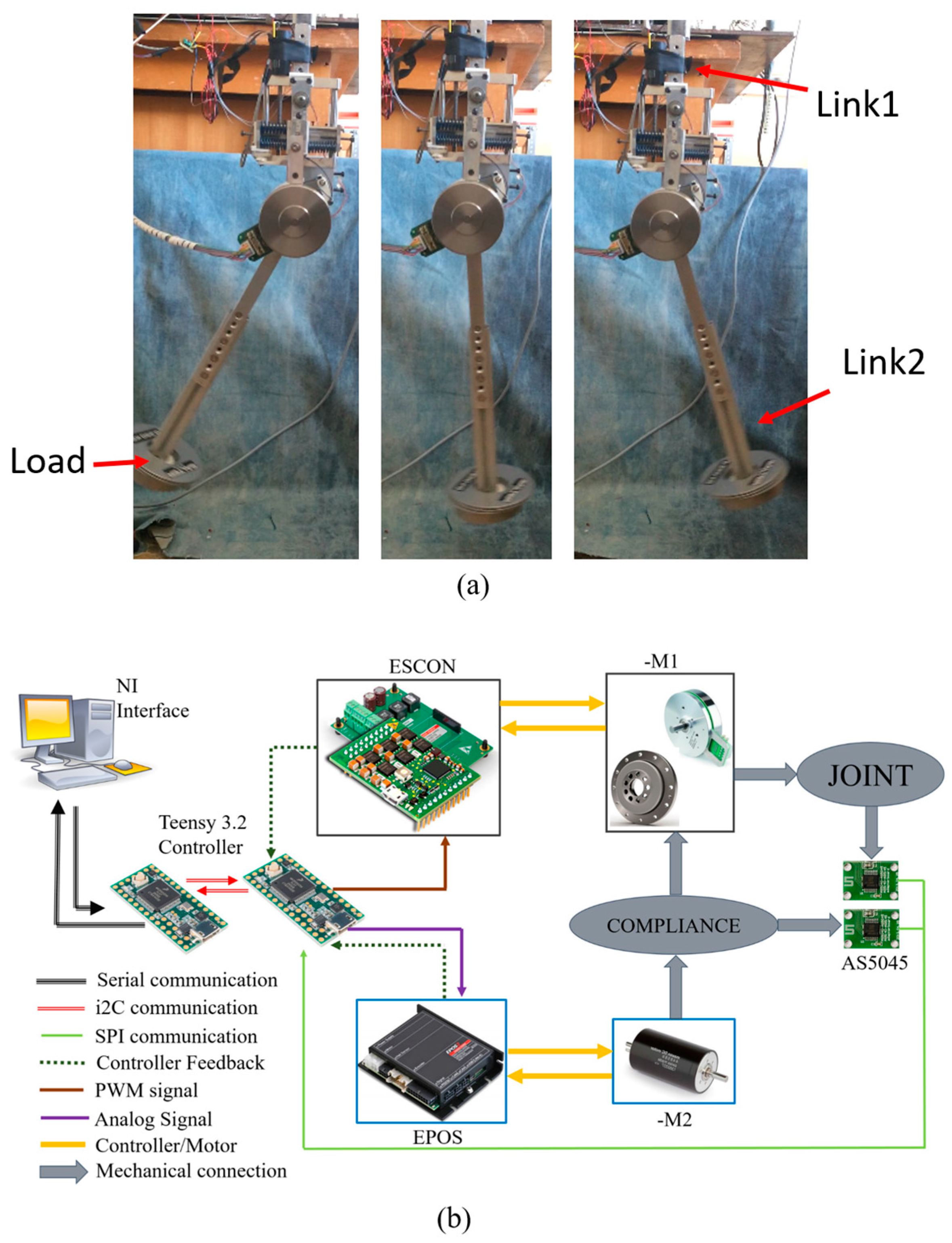
To evaluate the behavior of the actuator, several experiments were performed focused on testing the main advantages and versatility of the compliant system. The experimental setup used consisted of two articulated links resembling a joint from a robotic exoskeleton. Attached to the lower link, a link extension holding an adjustable load was set (See
Figure 6a).
To measure the compression of the springs in the compliant mechanism and the joint position, two absolute magnetic encoders (Austria Micro System AS5045) with custom boards are used. These provide a joint position resolution of ~0.09 degrees and more than 0.2 mm of resolution for the linear encoder that measures the spring compression.
The data acquisition and control of the experimental evaluations, see
Figure 6b, were made with the help of the Maxon motor controllers, Teensy 3.2 boards, and the National Instrument (NI) Labview Software. A master–slave configuration was implemented using 2 Teensy 3.2 boards with 72 MHz processors. The slave board is connected to the ESCON and the EPOS controllers. A pulse width modulation (PWM) signal commands the joint position at the main actuator
M1, by implementing a simple proportional-derivative (PD) controller with position feedback. An analog signal controls the position of the slider element by means of
M2. The data from the AS5045 encoders, along with current consumption, velocity, and position based on hall counts fed by the ESCON controller, are logged into the slave board. The master and slave are in continuous communication. Feedback data from the slave are sent via an i2C protocol to the master and are transferred every millisecond to a main computer with the NI software. Online kinematic data and current consumption were logged for offline data analysis.
From analysis of the gait biomechanics [
31], it is possible to identify several behaviors that the lower limb joint present during the locomotion cycle.
Table 1 presents a summary of the desire behaviors in a versatile joint, in order for these to be implemented in the joints of a lower limb exoskeleton. By designing and implementing appropriate joint trajectories, relevant capabilities of the ARES-XL can be tested in the bench test to prove the versatility of this novel actuator.
3. Results
The results and a more detailed explanation of the experimental assessment performed to ARES-XL are presented in this section. The force-measuring capabilities of the actuator as well as its versatility allowing the actuator to be implemented as a knee and ankle joint are also discussed.
3.1. Embedded Force Sensor: Torque Measurement
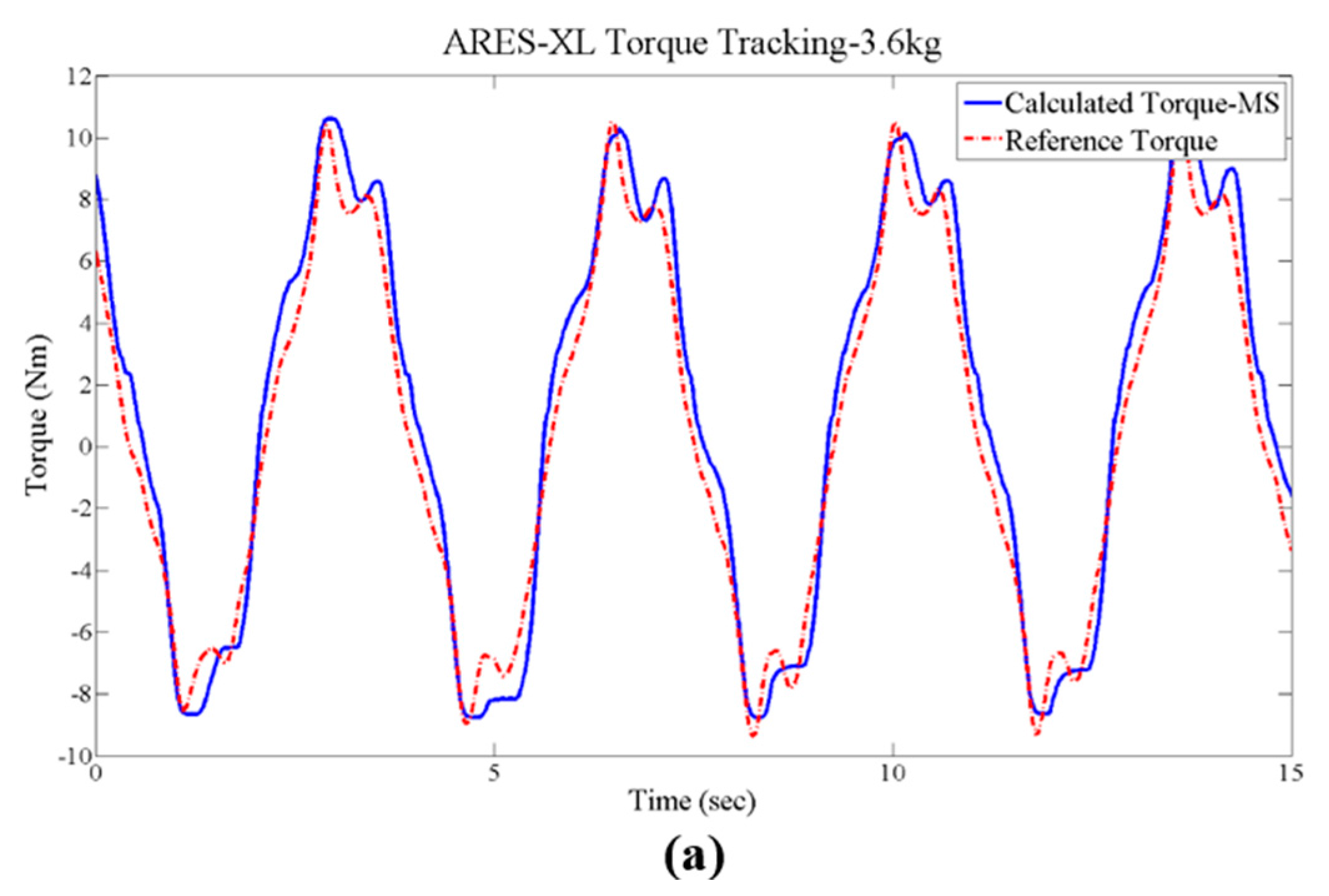
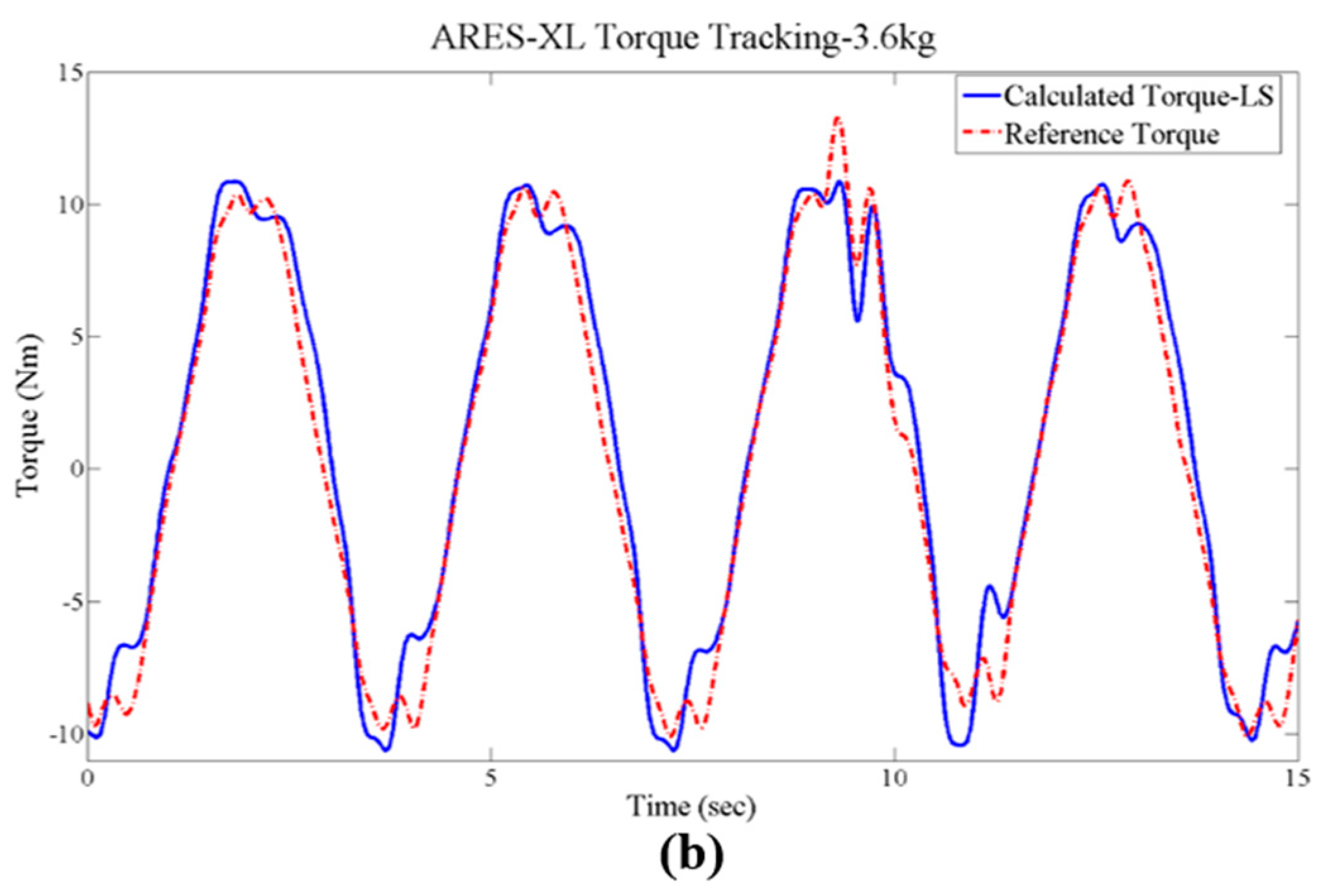
Torque tracking during operation is one of the main functionalities of this compliant joint. To validate the embedded force sensor in the prototype, sinusoidal trajectories were commanded to the joint; by adjusting the load in the lower link, a quasi-sinusoidal torque will result as a load is exerted at the joint.
The data obtained for two different levels of stiffness at a given load are shown.
Figure 7 shows the results after adjusting the load to 3.6 kg and an equivalent link arm of 360 mm. Torques up to ±10 nm were tested in this configuration at two different stiffness levels. The torque tracking fits closely with the theoretical torque calculated using the Newton–Euler formulation. Both stiffness levels seem to be suitable for the given load range with less than 0.5 nm error.
Low stiffness presented good torque tracking, although the spikes due to inertial loads diverge about 1 nm from the reference, contrary to the higher stiffness configuration. No significant delay in the tracking was evidenced during the experiment; in the tests with high stiffness and lower loads, the calculated torque can present delays around 0.1 s due to the reaction time in the springs. When the actuator is intended to be used for multiple purposes, and under different conditions, adjustments of the stiffness should be made depending on the resolution and precision desired of the torque tracking.
3.2. Ankle Emulation
The ankle joint during the gait cycle generates positive and negative power, as can be observed in works of clinical gait analysis such as [
32]. During almost the entire support phase, this joint is capable of behaving as a passive mechanism by adapting the joint position as a consequence of the foot loaded with the body weight and the ground contact, as shown in
Table 1. In the design of prosthetic devices and gait analysis a commonly discussed theme is the limitation of conventional electric motors to supply the necessary power for push-off at the end of the support phase, characterized by the requirement of high torque at high speed, similar to an impulsive torque. The ARES-XL is proposed as a suitable actuation system at the ankle. By implementing stiffness adjustment during the locomotion cycle in combination with the power generation of the main motor
M1, the ARES-XL is capable of providing a higher torque than its conventional stiff counterpart.
To validate the ARES-XL as a suitable actuation system for the ankle joint, a combination of a state machine and a specially designed trajectory were implemented in the experiment. Three particular cases were tested.
stiffness of the joint fixed at medium stiffness (MR);
compliance blocked, by mechanically constraining the elastic element in the compliant element (R) and making it work as a stiff actuator;
adjusting the stiffness during operation to exploit the dynamics of the system by implementing a state machine in the compliant mechanism (
AR), see
Figure 8.
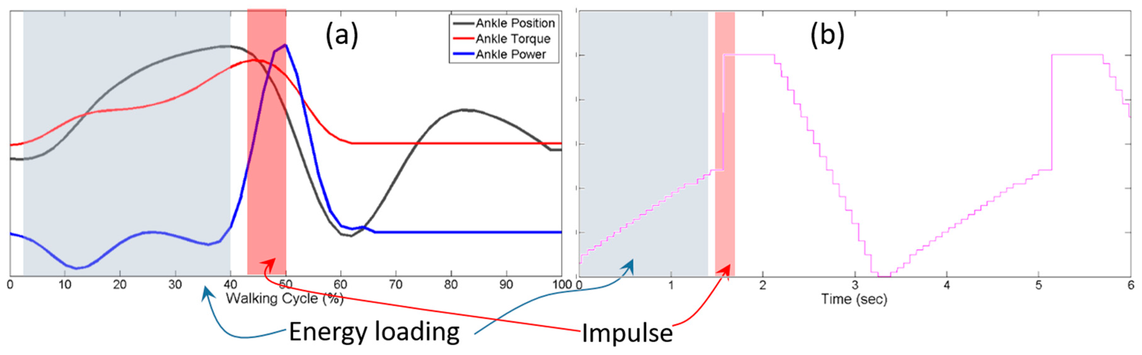
Figure 9 shows the logic behind the implemented trajectory. During the initial part of the motion, the joint load will gradually increase. This section of the trajectory emulates the support phase, and is followed by a step increment of the joint position, at the second highlighted area, similar to the push-up experienced at the toe-off. The actuator response will not be able to deliver this instant motion. The last section of the trajectory does not require high power or high speed, and the ankle at this point reaccommodates to continue the gait cycle.
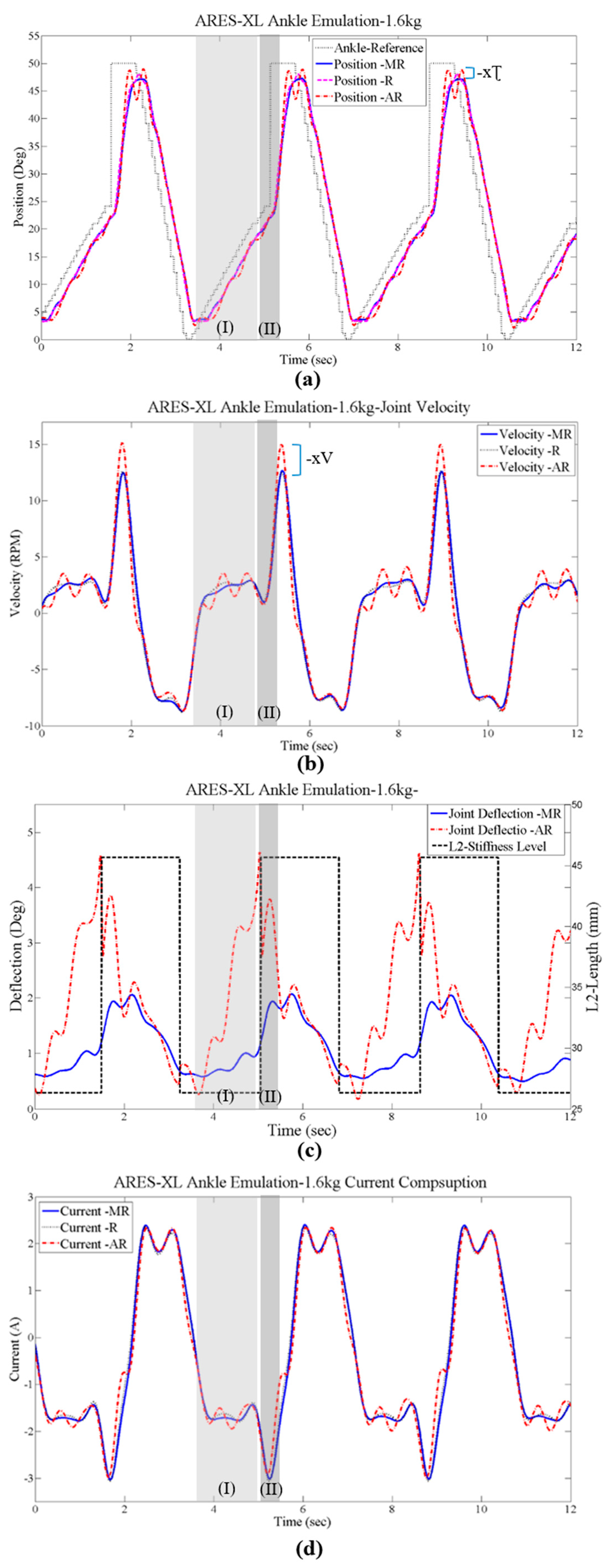
The implemented state machine can be observed in
Figure 10c, represented by the L2-Stiffness Level. The stiffness was adjusted between two different levels. A low stiffness of approximately 4 nm/deg during the emulation of the support phase is followed by a high stiffness of up to 10 nm/deg at the time that the step is commanded in the trajectory. The joint position for the tested cases are shown in
Figure 10a. The case
R is used as a comparison with a stiff actuation configuration, and as a consequence the c figure does not show deflection at the joint for this configuration. The
AR presents a higher slope when the step is commanded, reaching a higher peak than the other two cases. The position is related to the torque at the joint, thus the
AR configuration by presenting a higher peak and velocity shows evidence of achieving a slightly higher torque than the other cases.
During the emulated support phase (I), the
AR and
MR experiments present deflections at the joint. This deflection can be translated into energy stored at the joint when used as a passive mechanism. The deflection range achievable with ARES-XL gives this joint the capability of storing and buffering a large amount of energy passively during the support phase, and its wide range of stiffness adjustment allow the system to adjust to the weight of different subjects. At the push-off (II) the power at the joint changes, and with the test bench this condition cannot be replicated. However, it can be shown that in addition to the energy stored at the elastic elements, by adjusting the stiffness of the system an impulse is experienced at the joint. The deflection is a function of the stiffness, which when increased causes the joint deflection to decrease immediately. The energy is transferred directly to the joint and can be evidenced in
Figure 10b, indicated by
xV in the figure, by the significantly higher velocity of about 20–25% reached by the
AR compared to the other two cases.
During a dynamic locomotion cycle, the energy stored at the joint during the support phase can be used to reduce the power required by the main motor
M1. By adjusting the stiffness level during the cycle (I) and allowing the joint to store a larger amount of energy, followed by increasing the stiffness at the push-off (II), the deflection of the joint can contribute to a larger energy transferred to the joint, and as consequence, even less power will be required by the main motor.
Figure 10d shows the current consumption for the tested cases, evidencing that there were no significant differences in the main motor
M1 consumption while achieving a better step response and higher velocity at the joint with the
AR.
3.3. Knee-Swing Emulation
The knee joint presents multiple functions along the locomotion cycle. The actuator needs to be able to behave as a compliant joint with a large deflection, hold the energy stored, release it when commanded, and be capable of generating power when required. The ARES-XL should provide the following:
compliant behavior during the loading response; absorb energy by withstanding the body weight and flexing the knee close to 10 degrees, followed by extending the knee using the stored power during flexion;
at pre-swing flexion, just before toe-off the knee flexes over 10 degrees; the energy absorbed should be transferred to another joint or stored for later phases;
at the initial-swing, the knee generates power to continue the flexion to achieve a proper ground clearance;
at the final-swing, the knee flexes approximately 60 degrees and then extends to accommodate the leg for the heel strike; the swing is ideally a combination of the free joint and power generation to accommodate the correct extension.
From the ankle-emulation experiments and the intrinsic compliance of the system, the ARES-XL is capable of providing the desired behavior during the loading response. By setting the stiffness to a proper value based on the weight of the subject, the required flexion at the knee to absorb energy followed by the knee extension by decompression of the elastic elements when the load decreases can be achieved with the ARES-XL and its large range of deflection.
At the pre-swing, the stored energy will quickly try to release itself as soon as the leg leaves the ground, deviating the joint from its trajectory. This can translate to the main motor M1 working extra to compensate for the deviation of the joint from the commanded path. Some prosthetic devices dissipate the energy from this phase instead of taking advantage of it. Implementing the add-on locking mechanism, the deflection at the pre-swing can be locked to continue to the next phase, where the direction of the load changes while maintaining the same direction of rotation. The energy stored is not wasted nor opposing the natural motion. The energy supplied to flex the knee while the locking is engaged is used solely to produce the flection.
Finally, at the end of the swing, the stiffness of the system is set to a low value. Disengaging the locking mechanism at the same time allows a free swing without energy of at least the amount of deflection previously reached at the pre-swing, see
Figure 11.
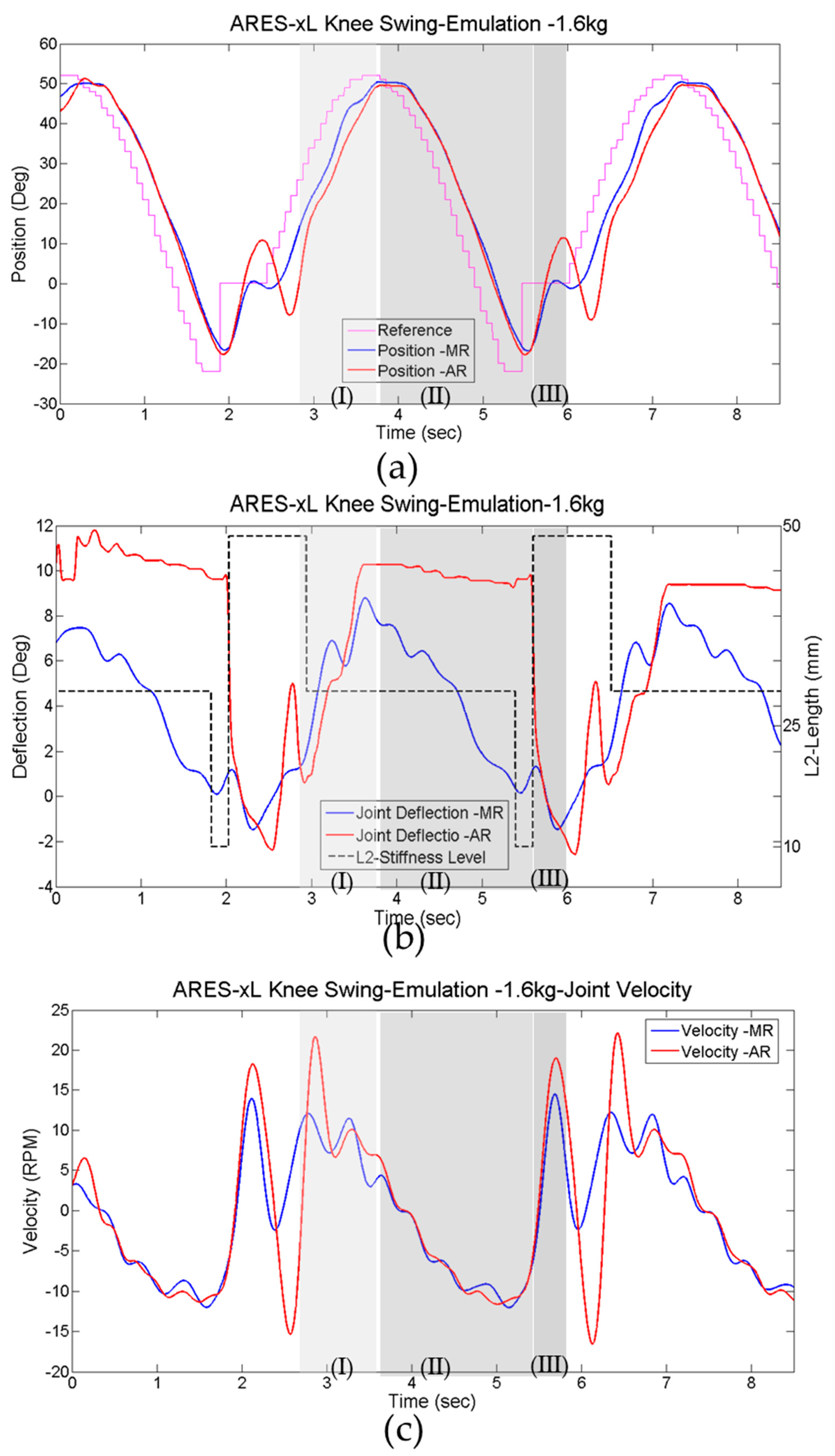
To validate the ARES-XL as an actuation system capable of storing the energy at the pre-swing and presenting a free swing motion, the trajectory is presented in
Figure 12, where (a) shows the implementation at the joint along a state machine to adjust the stiffness during the gait cycle. The following cases were tested:
adjustable stiffness to engage the locking, disengage and free swing (AR);
fixing the stiffness to present a compliant joint (MR).
The implemented trajectory, illustrated in
Figure 12a, gradually increases the torque exerted at the joint to resemble the pre-swing (I) of the gait. This is followed by a change in the rotation direction that will end with the joint loaded in an opposite direction than the one in the pre-swing (II). Finally, a step to zero was used to test the swing capability of the joint (III).
The test performed with fixed stiffness
MR (near 7 nm/deg), behaved similarly to a simple sine trajectory, as observed in
Figure 12b. The deflection at the joint was simply proportional to the load at the joint, which was expected due to the embedded force-sensor principle. With the implementation of a state machine for adjusting the stiffness of the system, the results for the experiment in the
AR case show that during the pre-swing
Section 1, the deflection was larger than 10 degrees with a low stiffness value close to 4 nm/deg. This large deflection in the desired direction caused the locking to engage as can be appreciated in
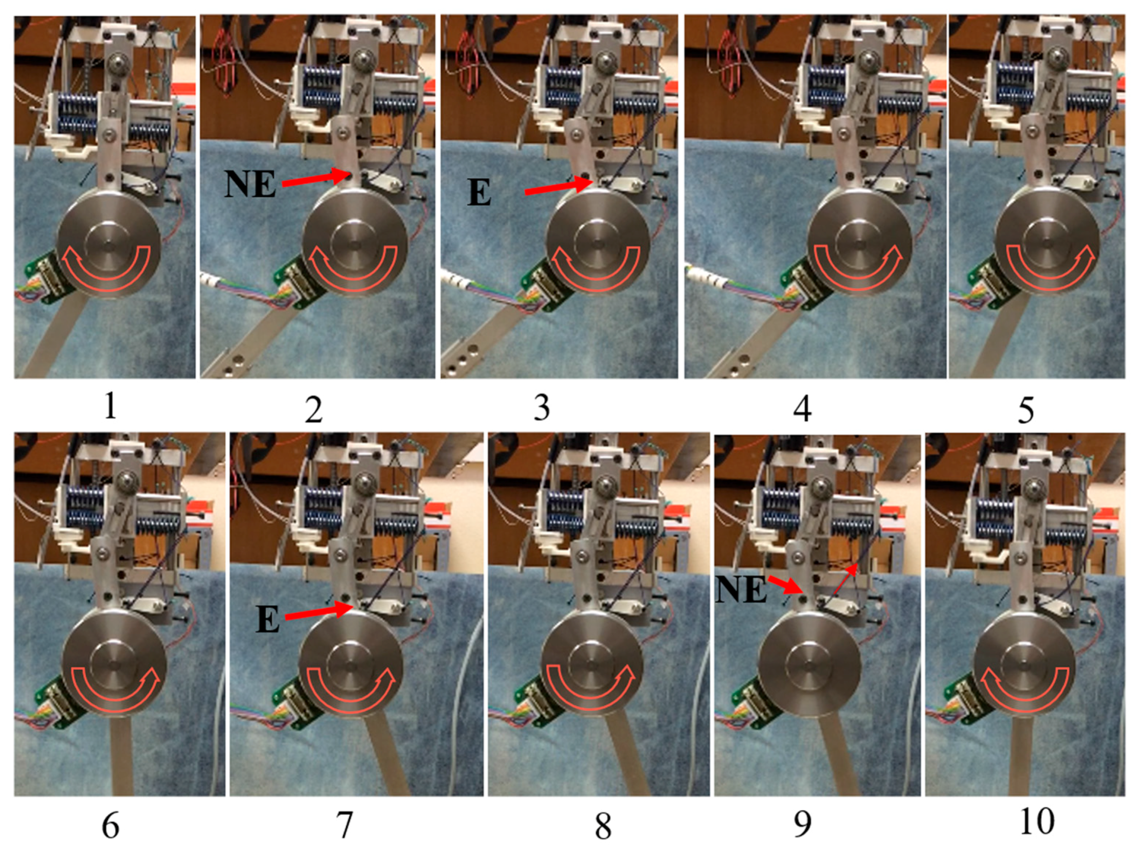
Figure 12b by the constant deflection at (II) highlighted with the dashed bubble, just before the swing emulation (III). With the deflection locked, the joint continued following the desired trajectory until the stiffness of the system was set to a minimum value near zero. At the end of the highlighted
Section 2, see
Figure 12b. The stiffness adjustment tensed the cable attached to the pawl
L1, forcing the locking to disengage, illustrated in the snaps 8–9 in
Figure 13. At this point (III), the stiffness of the system is near minimum with a deflection of more than 10 degrees from the pre-swing (I). Due to the potential energy and the energy previously stored now being released, the joint deflection drops rapidly to zero as shown in
Figure 12b. This is similar to the swing in human locomotion. The main motor is not required to supply power to achieve this motion. The joint moves freely due to the potential energy and the stored energy at the compliant mechanism.
Figure 12c shows how the velocity reached with the
AR is higher than that delivered with a simple compliant actuator. This velocity is directly related to the inertia of the link and its potential energy. Thus, it is implemented in a mechanism to achieve the swing of the knee and should result in a more natural and efficient movement.
The ARES-XL could be used at a knee joint to exploit its intrinsic compliance during the loading response, followed by accepting the weight of the body at the pre-swing and storing this energy for its release at the end of the swing. During the stages where the lock is engaged, the system was able to follow the correct trajectory without affecting the velocity profile.
When the knee behavior is analyzed along the healthy human locomotion cycle it is evident that by modulating its impedance little-to-no power needs to be actively delivered to this joint. Nevertheless, for powered prosthetics and more particularly exoskeletons, the knee needs to present an active source of energy capable of compensating the drawbacks caused by slow gaits, response to external disturbances, and to assist during ground clearance. Another important function of an active energy source at the knee, is the possibility of climbing stairs or going uphill. The ARES-XL with the implementation of the add-on locking mechanism represents a very good alternative for powering knee joints in exoskeletons and powered prosthetics, that presents the benefits of a passive joint along gait, without limiting its functionality for different tasks; more importantly, it provides safety to the user by being capable of compensating trajectory errors due to users’ spasticity, external disturbances or other factors.
4. Conclusions and Future Work
Many research groups have been working to develop adjustable compliant actuators. However, it has been accepted by many researchers that there is no perfect nor optimal design. Actuators need to be designed oriented to the desired application and operation. Conversely, some common characteristics can be identified on many designs, such as the working principles for achieving stiffness adjustments and compactness.
This paper presented a new compliant actuator designed to be force-controlled and compliant. The lateral size is reduced, when compared to other SoA VIAs from the same category, by taking advantage of the different elements included in the system to achieve different tasks, such as the compliant behavior due to the elastic elements and their utilization to achieve a good torque measure, with adjustable range and resolution. The results from the prototype assessment reveal that the adjustable rigidity is closely related to the torque-measurement scale. Through proper adjustments, the actuator can be controlled for different functions, such as rehabilitation or walking at different speeds. Different stiffness configurations can produce more or less deflection at the joint at a given torque. Adaptability can be tuned for different subjects based on the load transferred to the exoskeleton joints.
When compared side by side with other prototypes, see
Table 2, the ARES-XL presents several relevant properties that give an advantage to our actuator in order to be implemented in our intended application. The large range of deflection allowed at the joint makes it suitable for storing significant energy in its elastic elements. The arrangement of the components maintain the lateral size as low, which is beneficial for robotic exoskeletons. ARES-XL provides actuation versatility, because of its range of stiffness, torque-measuring capabilities, and impedance-adjustment times. The locking mechanism included in the ARES-XL actuator proved to be successfully engaged, blocking the deflection at a given position. When the locking control strategy was implemented, the load exerted when the system is locked does not affect the previous deflection nor cause the pawl to disengage. The energy stored at the knee can be harvested and released in a non-consecutive phase of the gait taking advantage of the biomechanics of the gait.
From the experiment, at the pre-swing, the body weight can produce deflections at the knee up to 20 degrees. This deflection could later translate to 20 degrees of extension by means of reusing potential energy at the end of the swing.
Taking advantage of the larger deflection allowed by the ARES-XL, energy can be passively stored into the elastic elements during the approximate 20 degrees of dorsi-flexion in the ankle during the support phase. This energy could be reutilized during the push-off by quickly adjusting the stiffness to a higher level. As a consequence of the stiffness adjustment, the deflection will transfer energy to the joint position as movement in the direction of the exerted torque. This transferred energy combined with the remaining energy in the elastic elements and the main motor actuation can generate an impulsive reaction at the joint higher than that achievable solely with the main motor actuation. This reaction results in a torque generation at a speed rate that is significantly higher than that achieved with the stiff configuration or fixed compliance at the joint. The locking mechanism is not necessary for this joint as the locking functionality acts when the torque exerted at the joint changes direction, whereas the motion continues its trend—such as in the pre-swing to mid-swing of the knee. For this case, the add-on locking mechanism is simply removed from the mechanism by decoupling the Pawl L1.
Future work will address the implementation of the ARES-XL with a proper control algorithm in the joints of a robotic exoskeleton, as well as size optimization of the mechanism and its main components.


