Article

Static and Dynamic Studies of Electro-Active Polymer Actuators and Integration in a Demonstrator

1
Université Grenoble Alpes, F-38000 Grenoble, France
2
CEA-LETI, MINATEC Campus, F-38054 Grenoble, France
3
CEA, LITEN, DTNM, LCEI, F-38054 Grenoble, France
4
Arkema-PiezoTech, F-69493 Pierre Benite, France
5
Walter Pack, S-48140 Bizkaia, Spain
6
IEMN UMR CNRS, 8520, Avenue Henri Poincaré, F-59652 Villeneuve d’Ascq, France
7
Menapic, 41 Bd Vauban, F-59046 Lille, France
*
Authors to whom correspondence should be addressed.
Actuators 2017, 6(2), 18; https://doi.org/10.3390/act6020018
Submission received: 30 January 2017 / Revised: 9 April 2017 / Accepted: 27 April 2017 / Published: 4 May 2017
(This article belongs to the Special Issue MEMS-based Actuators)

Abstract

:
Nowadays, the haptic effect is used and developed for many applications—particularly in the automotive industry, where the mechanical feedback induced by a haptic system enables the user to receive information while their attention is kept on the road and on driving. This article presents the development of a vibrotactile button based on printed piezoelectric polymer actuation. Firstly, the characterization of the electro-active polymer used as the actuator and the development of a model able to predict the electromechanical behavior of this device are summarized. Then, the design of circular membranes and their dynamic characterization are presented. Finally, this work is concluded with the construction of a fully functional demonstrator, integrating haptic buttons leading to a clear haptic sensation for the user.

1. Introduction

Haptics is widely used in several high performance areas. Using this technology, the sense of touch is stimulated by applying forces, vibrations, or motion. In the automotive industry, beyond the technological value, it has real life applications in the security domain. More precisely, the mechanical feedback induced by the haptic button allows the user to receive information while his attention is kept on the road and on driving [1]. Dashboard integration of various tactile sensations is particularly interesting [2]. These haptic sensations can be produced by actuators integrated in microelectromechanical systems (MEMSs). Even a slight displacement of a few microns in amplitude is felt by the finger [3]. The actuation can be induced using diverse means, such as shape memory alloys [4], eccentric rotating mass [5], or piezoelectric materials [6]. In this study, a piezoelectric material has been chosen to actuate the vibrotactile button, and the actuation principle is based on the unimorph effect, which enables an out-of-plane displacement. Many piezoelectric materials are used in the industry, such as PZT (Pb(Zr0.52, Ti0.48)O3) or aluminum nitride (AlN), but they need to be processed at high temperatures, which is incompatible with the polymer substrates. To overcome this thermal constraint and allow the polymer technology to be compatible with car dashboard integration, an electro-active polymer (EAP) has been used for the haptic actuators. A vibrotactile display for mobile applications has been developed by Matysek et al., using a dielectric elastomer stack [7,8]. This technology allows for the total displacement of a few microns, but the applied voltage ranges from 150 to 1500 V, which causes a number of problems, especially concerning security issues. Piezoelectric EAPs are a good alternative in the development of flexible devices that present large displacements at a lower actuation voltage [9].
In this paper, the development of a vibrotactile haptic button is presented. The EAP material and the technology used to build demonstrators are detailed. In particular, material properties investigations using picosecond ultrasonics (PU) are presented. Analytical calculations and finite element method (FEM) models were used to design the vibrotactile buttons and the optimization of the actuator design are reported. A first model allows the calibration of the material database by a static study of a cantilever. After the technological realization, the vibrotactile button was characterized dynamically. A second FEM model has been developed, corresponding to the full study of a circular membrane, and the geometry integrated in the dashboard. A static study was performed to extract design rules in order to get the best haptic performances. A dynamic study allows the identification of the first mode resonance frequency, where the maximum displacement is the highest and therefore the greatest haptic effect. An acceptable agreement between modeling and measurement is observed, with a discrepancy from 3% to 10%. It validated our model and the vibrotactile buttons were integrated in a demonstrator leading to a clear haptic sensation for the user.

2. Materials and Methods

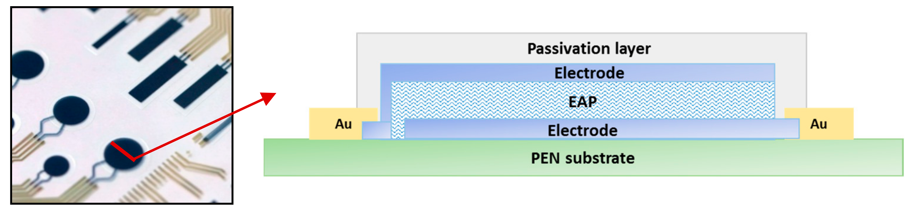
2.1. Electro-Active Polymer

PVDF (Polyvinylidenefluoride) and fluorinated electroactive polymer derivatives are subject to numerous developments in the field of flexible and organic electronics. Thanks to their ferroelectric semi-crystalline structures, they exhibit piezoelectric, pyroelectric, or even relaxor ferroelectric properties that open new perspectives for sensor and actuator applications. Among them, P(VDF–TrFE) (Poly vinylidenfluoride-co-trifluoroethylene) copolymers are of particular interest since they crystallize directly from a solution in a ferroelectric phase and can be processed through standard printed electronic techniques [10].
Piezoelectric EAP actuators have been manufactured out of polymer substrates, such as polyethylene naphtalate (PEN). Firstly, a 50 nm gold layer has been deposited by physical vapor deposition (PVD) on the PEN. The piezoelectric stack consists of a PVDF–TrFE film with a thickness of 4.7 µm in between the PEDOT–PSS bottom and top electrodes. The thickness of each electrode is 800 nm. Both of them are connected to metallic pads in order to ensure the electrical connection. A passivation layer is finally deposited to protect the hydrophilic electrodes. Figure 1 shows a schematic cross section of the polymer stack. The whole process used to build the piezoelectric stack is done by screen printing. After each deposition, the layer is annealed for 15 min at 135 °C in an infrared oven. It allows the solvent to evaporate and the PVDF–TrFE film to crystallize [11].
In order to activate the piezoelectric effect of the copolymer, actuators are poled with a squareform signal at a low frequency (1 Hz) for a period of 120 s at 200 V. This poling step induces the alignment of dipoles in the direction of the electrical field.
Figure 1 shows a photograph of the printed actuators, manufactured using the process flow explained above. The homogeneity of each layer has been validated and the expected thicknesses are observed. Numerous geometries can be realized, as long as they respect the design rules of screen printing technology. In this article, only simple geometries, cantilevers and circular membranes, will be presented.
Material properties of the copolymer were investigated in order to determine Young’s modulus and therefore to be more precise during further modeling and simulations. To achieve this, the PU technique was used on a sample with a piezoelectric EAP layer (PVDF–TrFE) deposited above an aluminum layer (50 nm, see Figure 2a). PU involves the use of a femtosecond laser to perform SONAR-like measurements at the nanoscale [12]. A first ultra-short laser pulse, called a pump pulse, generates a thermal strain in the Al layer. Consequently, this induces the propagation of an out-of-plane longitudinal acoustic wave in the piezoelectric EAP layer. A second laser pulse (the probe) time-delayed with respect to the pump pulse is used to optically detect the propagation and the reflection of the acoustic pulse in the sample. The acoustic propagation in the piezoelectric EAP layer is first detected as an oscillation clearly visible in Figure 2b. Such an acousto-optic oscillation is governed by an optical index and the sound velocity in PVDF [13]. When the pulse reaches the free surface, approximately around 100 ps, a sudden variation of reflectivity is detected as the acoustic pulse reflects [14]. Both phenomena can be used to extract thickness and sound velocity in the piezoelectric EAP layer. In Figure 2b, the numerical modeling of the whole signal is plotted. The numerical model implements the photo-acoustic emission in the buried Al layer and the optical detection of the strain pulse through two mechanisms: photo-elastic detection and the reflectivity step in the transparent layer [14,15]. The main parameters for the model are the optical index, the sound velocity, the mass density, and the thickness of the successive layers of the materials involved and the photo-elastic constants in Al and in PVDF. To obtain the agreement visible in Figure 2b, the optical index, the photo-elastic constants and mass density, the thickness, and the sound velocity of the Al layer are fixed values, and the sound velocity, the mass density and the thickness of the PVDF layer are adjusted. A good match is obtained using an optical index of 1.5, a thickness of 214 nm, a sound velocity of 2100 m/s, and a mass density of 1.78 g·cm−3. Finally, using the theory of elasticity and assuming a Poisson’s ratio of 0.4 [16], the piezoelectric EAP Young’s modulus can be extracted from the longitudinal sound velocity, giving a value of 3.6 GPa.

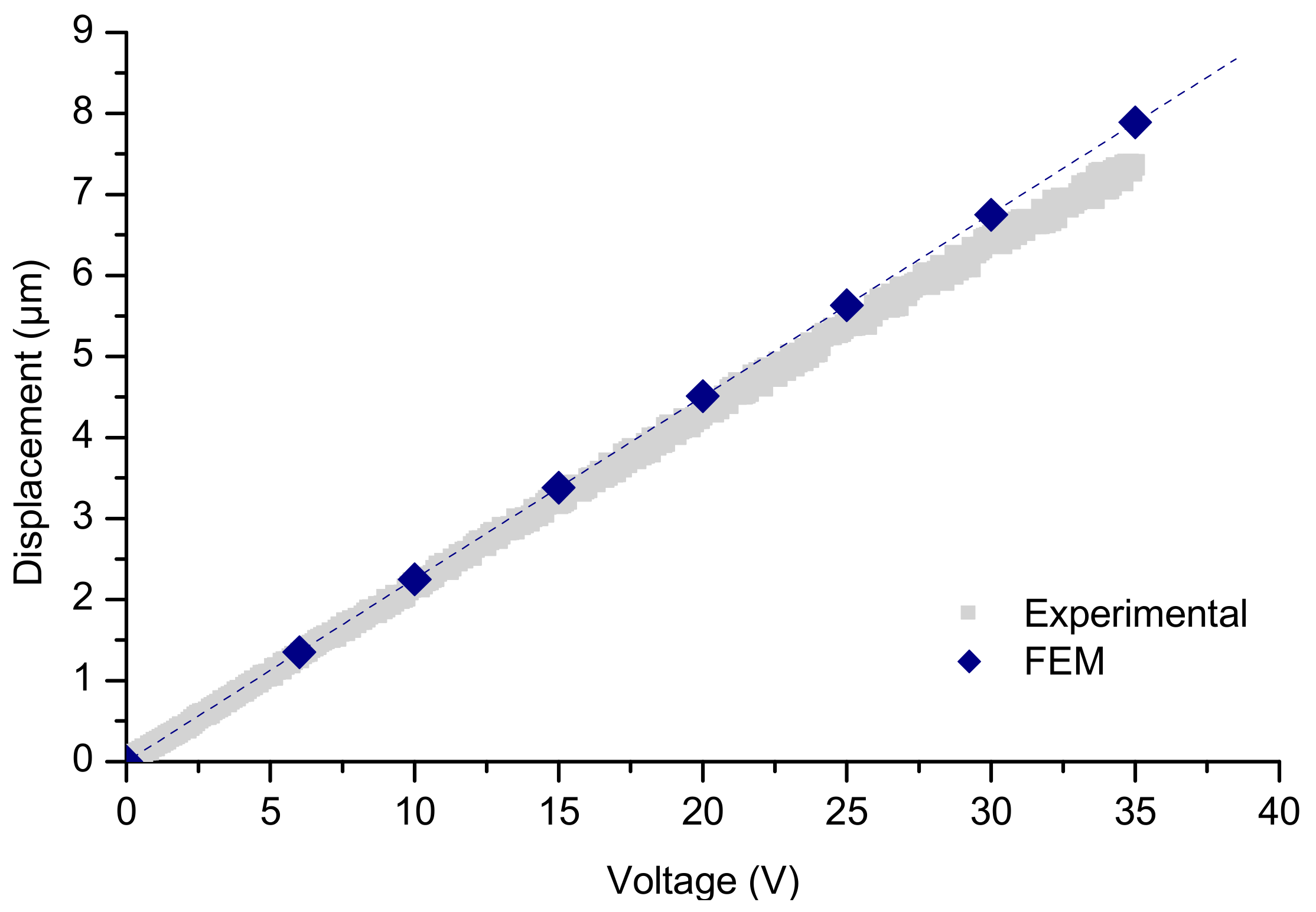
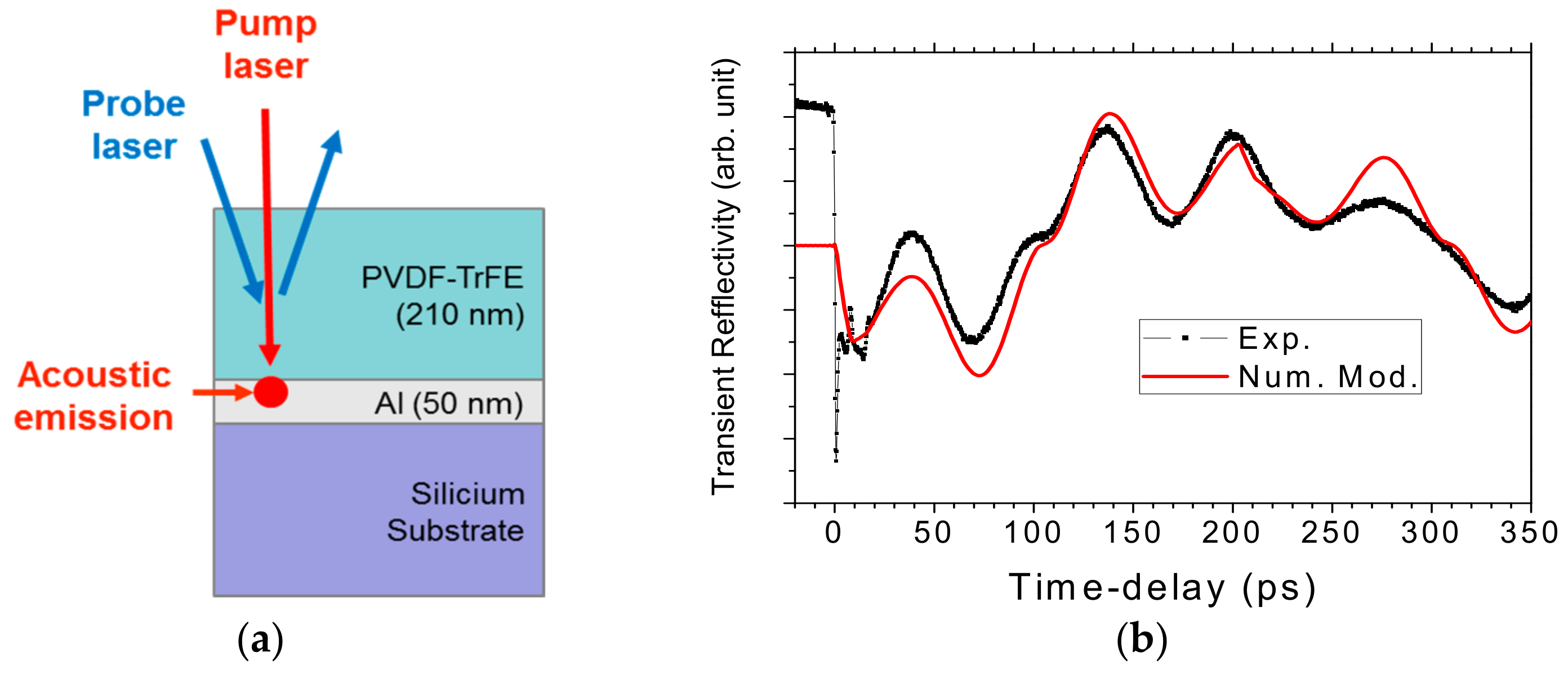
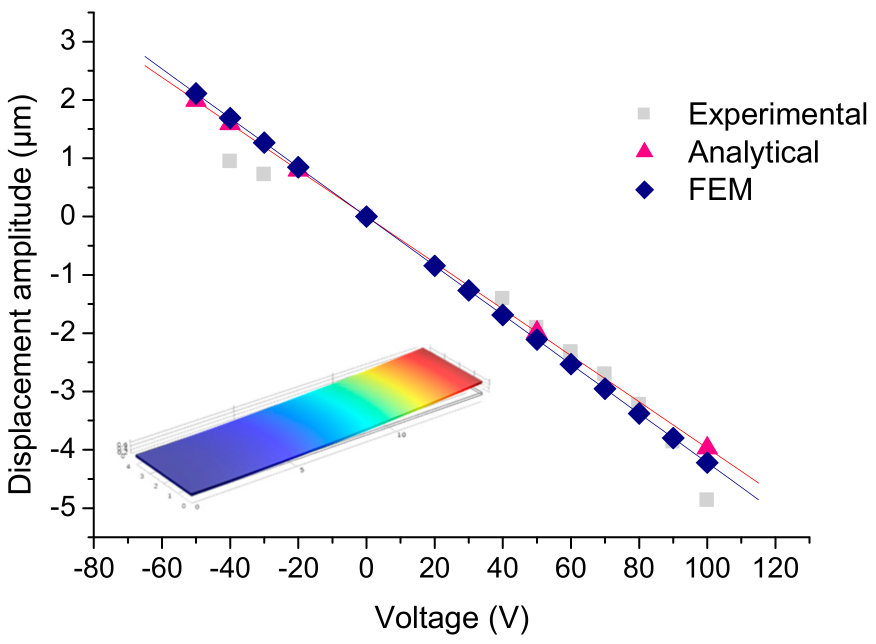
2.2. Calibration of FEM Model on Cantilever Geometry

To calibrate the developed model, the comparison between the measured maximal displacement of a cantilever under a given actuation voltage with the simulated one using an analytical calculation is performed [17].
The study is realized on a polyethylene naphtalate (PEN) cantilever (Teijin DuPontFilms, Japan) that is 1.45 cm long, 0.3 cm wide, and 125 μm thick, with a 1.2-μm-thick PVDF–TrFE actuator from PiezoTech. The piezoelectric and the unimorph effects are used to actuate our component. In this case, the piezoelectric EAP layer expands when an electric field is applied to it, while the PEN substrate is not affected. This results in a bending deformation of the cantilever. Measurements were performed by applying an actuation voltage between the top and the bottom electrodes using a RADIANT Multiferroic tool. The cantilever displacement amplitude determination has been done using a chromatic confocal sensor STIL Initial, which allows the measurement of displacements without physical contact. For the considered cantilever, the maximum differential displacement is 4.9 µm at 100 V.
Material properties were adjusted in order to correlate the analytical calculation with the measured results. In particular, an EAP piezoelectric coefficient of −3 pC/N has been extracted. The Table 1 summarizes the main properties of the copolymer PVDF–TrFE with the d31 adjusted from this study.
The adjusted material database was introduced into a FEM model. COMSOL Multiphysics software was used for the FEM approach. It was used to simulate the maximum displacement of the cantilever in a static study, meaning that a DC voltage is applied on the electrodes and the displacement of the cantilever is observed. Top and bottom electrodes are neglected due to their low impact on the mechanical behavior. In this model, each layer is considered isotropic and elastically linear.
As shown on Figure 3, there is an acceptable agreement between the finite element model, analytical calculation, and the measured results on the 1.45 cm long cantilever based on the piezoelectric EAP actuator. For all of them, at least five distinct voltages were tested. As expected, it reveals the linear behavior of the piezoelectric EAP actuator in this voltage range. It validates the FEM model.

3. Vibrotactile Circular Membrane Development

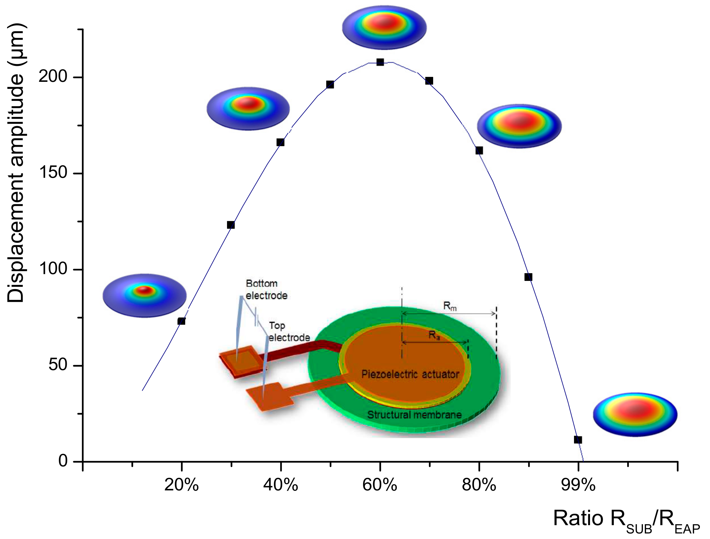
3.1. Static Study: Optimization of the Actuator

From the cantilever model explained in the previous part, a FEM model for circular geometry was developed. The circular membrane is fixed along its circumference. A circular actuator (top electrode/piezoelectric EAP/bottom electrode) is stacked above the membrane and fixed between the contact surfaces. Optimization of the piezoelectric EAP actuator design for circular membranes was realized using a static study. The optimum ratio between the piezoelectric polymer radius and the membrane radius was determined, in order to obtain the maximum membrane displacement along the z-axis, leading to the best haptic performances. The membrane displacement amplitude was simulated under a given DC actuation voltage, while the ratio between the actuator radius and the membrane radius was varied from 20% to 100%. As shown in Figure 4, a piezoelectric EAP radius equal to 60% of the membrane outer radius offers the greatest amplitude displacement regardless of the considered outer membrane radius and substrate thickness. Therefore, this design rule was selected for further development.

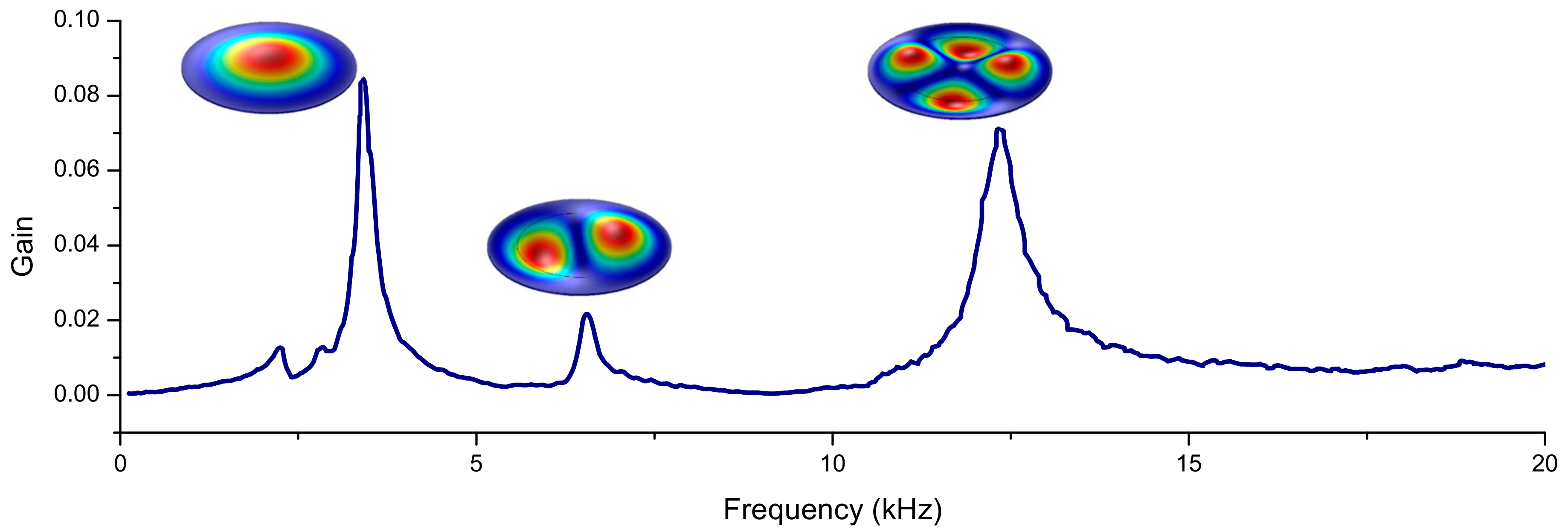
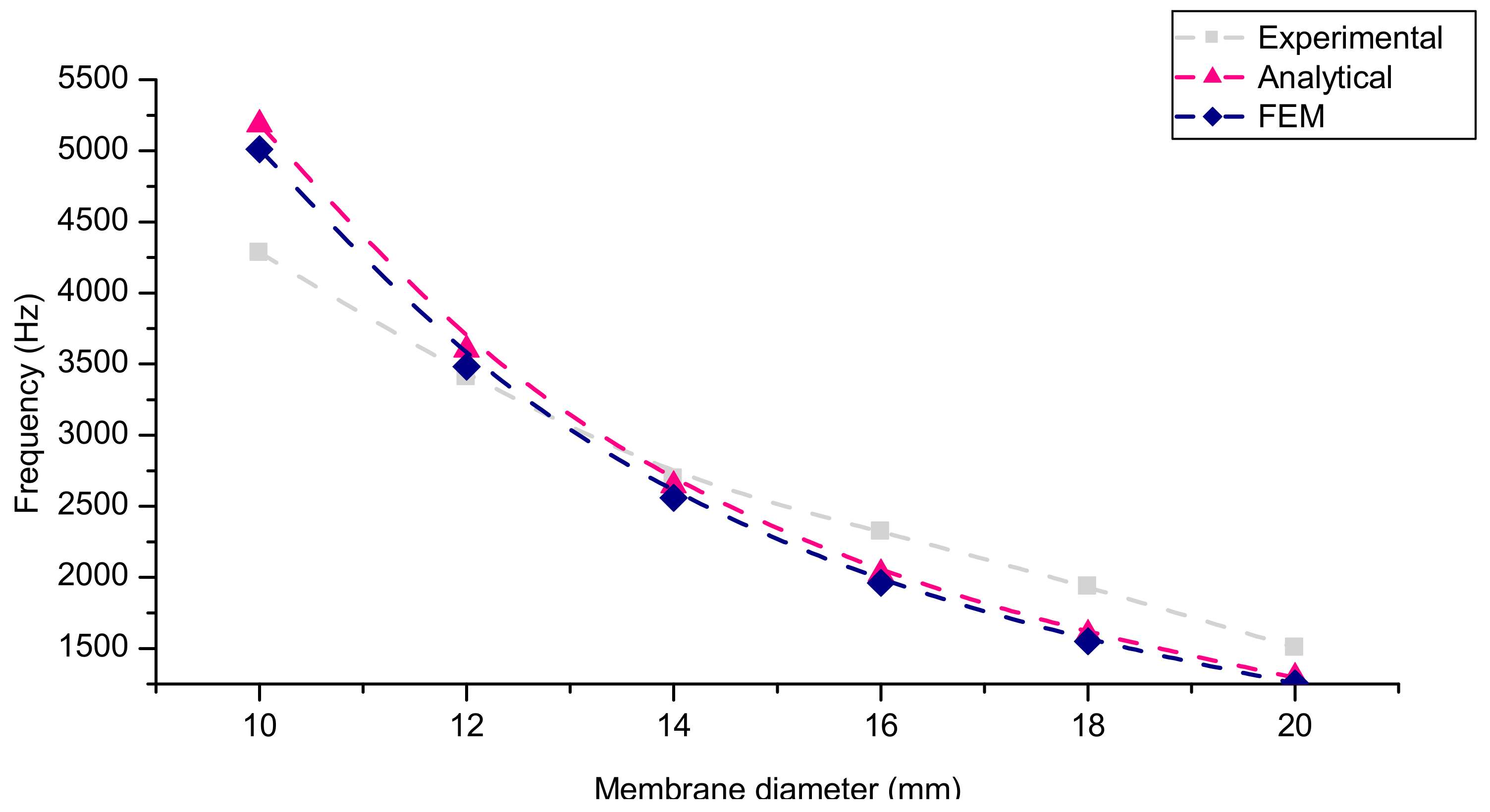
3.2. Dynamic Study: Development of Vibrotactile Buttons Based on Piezoelectric EAP Actuation

The aim is to develop a vibrotactile button. Hence, the vibration generated by the membrane should be felt by the finger, meaning that the displacement has to be in the order of micrometers.
Characterization in dynamic conditions of circular membranes designed previously was performed. Actuator dimensions used in this study follow the design rule defined previously, i.e., that the actuator radius is equal to 60% of the membrane outer radius, in order to get the maximal displacement amplitude.
Optical measurements of the piezoelectric EAP-actuated vibrating membranes were performed using laser Doppler vibrometry. The equipment uses interferometry to measure the velocity of the vibrating points of the membrane surface. A sinusoidal AC voltage is applied to the actuator. This actuation mode induces the vibration of the membrane, and a vibrotactile button is therefore obtained.
For each membrane diameter, from 10 to 20 mm, the same protocol was followed. Firstly, a frequency sweep from 0 to 20 kHz was performed, in order to identify the resonance frequencies, and especially the first vibration mode presenting the largest vibration amplitude, which is required for this application. In Figure 5, each peak corresponds to a vibration mode. Areas and amplitudes of peaks are not representative of the displacement because the measurement is performed at the center of the membrane, and depending on the mode, the maximum displacement is not always located at this specific point. Thus, the precise frequency was determined manually by finely tuning around the frequency determined in the previous step. The vibration mode is finally imaged in order to validate the shape and measure the displacement amplitude of the membrane. For each step, a voltage of 6 VRMS was applied to the actuator.
The deflection of a 12 mm membrane is illustrated on Figure 6. The first resonance frequency is 3.410 kHz, and the shape corresponds to the expected one. The corresponding dynamic displacement measured on this membrane can be extracted as being 1.4 µm.
These measurements were compared to the FEM model developed to predict the resonance frequencies and the corresponding displacement amplitude. In a first phase, the first resonant mode was studied. To calculate the frequency of the first resonance mode and its displacement amplitude, a two-part model was set up. First, the first mode frequency is calculated using an Eigen frequency study, also called a modal study. Then, from this value, the damping factor is adjusted, and the displacement of the membrane is calculated at this specific frequency thanks to a “frequency domain” study. The damping factor (d) is determined according to Rayleigh’s model, by the following equation [18]. The parameter depends on the resonance frequency of the first mode (f0) and the damping ratio (ξ).
d = 4 × ξ × π × f 0
The frequency of the first resonance mode is calculated for each membrane diameter, from 10 to 20 mm. For example, a 12 mm diameter membrane has a frequency of the first resonance mode of 3.483 kHz. Given that the measured frequency is 3.410 kHz, an acceptable agreement between experimental values and simulations (mismatch inferior to 3%) is observed. In addition, in order to confirm results from the FEM model, an analytical model has also been used, and the calculated frequency was 3.602 kHz [18]. The expression of the calculated frequency is detailed in the following equation.
f r = λ n 2   t 2   π   r 2   E 12   ρ   ( 1 υ 2 )
where
  • E: Young’s modulus (Pa);
  • ν: Poisson’s ratio;
  • ρ: density (kg·m−3);
  • t: thickness (m);
  • r: membrane outer radius (m);
  • λn: Eigenvalue at the n resonant mode (for the first mode, λ1 = 3.196).
The error percentage between simulations and analytical calculations is less than 5%, which confirms the capacity of the model to predict the resonance frequency of the first mode. Figure 7 illustrates the comparison between the resonance frequencies of the membranes with diameters ranging from 10 to 20 mm extracted from the FEM model, the analytical model, and the measurements performed with the laser Doppler vibrometer.
The displacement of the membrane is simulated for each diameter, as a function of the voltage applied on the actuator, from 0 to 35 VRMS. Figure 8 illustrates the maximal displacement of a 12 mm diameter membrane as a function of the voltage, simulated with the developed FEM model and measured with the laser Doppler vibrometer. It can be observed that the simulation is able to predict the displacement amplitude measured experimentally, with an acceptable precision of 10% whatever the applied voltage. Under 35 VRMS, the membrane has a deflection of 8 µm, which is a large deformation for this actuation voltage compared to the literature [8]. As expected, the displacement amplitude of the membrane has a linear dependence with the voltage until 25 VRMS [19]. For higher actuation voltages, a mechanical nonlinear contribution was observed for experimental values. This can be explained by ferroelectric properties of the piezoelectric polymer.

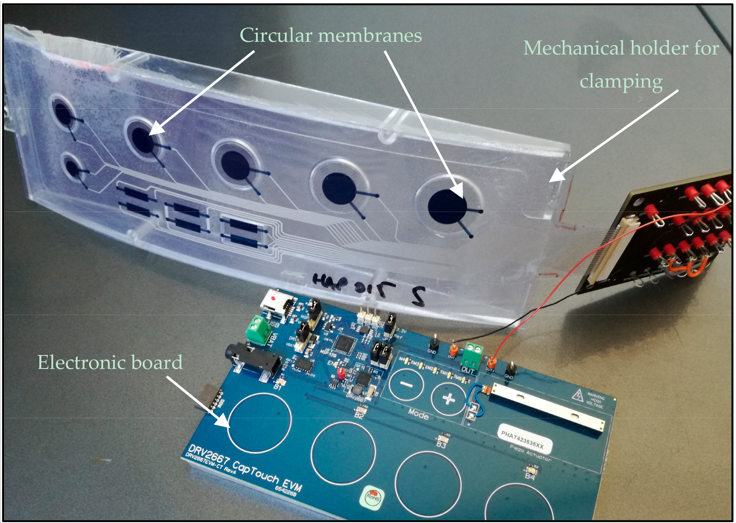
3.3. Haptic Demonstrator

Circular membranes with the optimized design studied statically and dynamically were integrated on a mechanical framework, permitting the clamping. It was built using injection technology, and polymer membranes were overmolded. A commercial electronic board drove the haptic buttons. This digital interface, developed by Texas Instruments (DRV2667 Evaluation Module, Dallas, TX, USA), permits the control of the membranes by actuating them with separated programmed modes. When membranes are actuated, they vibrate and the haptic feedback is clearly felt by the user, validating results presented previously and developed models. Figure 9 illustrates the demonstrator connected to the driving electronic board. The next step is the introduction of this kind of haptic interface in a car dashboard in order to test in driving conditions.

4. Conclusions

In this paper, we present the development and the calibration of an analytical and a FEM model. We used it to optimize the design of piezoelectric EAP actuators able to induce the vibration of a circular membrane to be used as vibrotactile buttons. Demonstrators were built using polymer technology and using piezoelectric EAP actuators. Characterization results, which correspond to modeling, show promising results.
Vibrotactile buttons resulting from these studies have proven their efficiency by being integrated in a fully functional haptic prototype, composed of a plastic injected framework and coupled to an electronic board. Vibrotactile haptic feedback is clearly felt by the user.
Finally, it is interesting to note that superior modes can be used to obtain various haptic effects. It could be an interesting way to obtain multisensory buttons that can potentially mix haptic and audible effects useful for a sightless user.

Acknowledgments

The authors wish to acknowledge all participants from the HAPPINESS project for giving us the opportunity to work on this project. This project has received funding from the “European Union’s Horizon 2020 Research and Innovation Program” under grant agreement No. 645145.

Author Contributions

Pauline Poncet performed the modelization and the static and dynamic characterizations, and wrote the paper; Fabrice Casset supervised the modelization, the characterization, and the writing of the article, and wrote the material characterization section; Antoine Latour was in charge of the technological realization; Fabrice Domingues Dos Santos provided the electro-active polymer; Sébastien Pawlak developed the mechanical framework; Romain Gwoziecki managed the corresponding European project; Stéphane Fanget supervised the design and characterization work; Arnaud Devos and Patrick Emery performed the picosecond ultrasonic measurements.

Conflicts of Interest

The authors declare no conflict of interest.

References

  1. Hayward, V.; Astley, O.R.; Cruz-Hernandez, M.; Grant, D.; Robles-De-La-Torre, G. Haptic interfaces and devices. Sens. Rev. 2004, 24, 16–29. [Google Scholar] [CrossRef]
  2. Zoller, I.; Lotz, P.; Kern, T.A. Novel thin electromagnetic system for creating pushbutton feedback in automotive applications. In Proceedings of the International Conference on Human Haptic Sensing and Touch Enabled Computer Applications, Tampere, Finland, 13–15 June 2012; pp. 637–645. [Google Scholar]
  3. Watanabe, T.; Fukui, S. Method for controlling tactile sensation of surface roughness using ultrasonic vibration. In Proceedings of the 1995 IEEE International Conference on Robotics and Automation, Nagoya, Japan, 21–27 May 1995; pp. 1134–1139. [Google Scholar]
  4. Elspass, W.J.; Kunz, A.M. Portable haptic interface with active functional design. Proc. SPIE 1999, 3668, 926–932. [Google Scholar]
  5. Siegel, E. Haptic Technology: Picking up Good Vibration; EE Times: San Francisco, CA, USA, 2011. [Google Scholar]
  6. Mastronardi, V.M.; Guido, F.; De Vittorio, M.; Petroni, S. Flexible force sensor based on c-axis oriented aluminum nitride. Procedia Eng. 2014, 87, 164–167. [Google Scholar] [CrossRef]
  7. Matysek, M.; Lotz, P.; Flittner, K.; Schlaak, H.F. Vibrotactile display for mobile applications based on dielectric elastomer stack actuators. Proc. SPIE 2010, 7642, 76420D. [Google Scholar]
  8. Lotz, P.; Matysek, M.; Schlaak, H.F. Fabrication and application of miniaturized dielectric elastomer stack actuators. IEEE/ASME Trans. Mechatron. 2011, 16, 58–66. [Google Scholar] [CrossRef]
  9. Ling, Q.D.; Liaw, D.J.; Zhu, C.; Chan, D.S.H.; Kang, E.T.; Neoh, K.G. Polymer electronic memories: Materials, devices and mechanisms. Prog. Polym. Sci. 2008, 33, 917–978. [Google Scholar] [CrossRef]
  10. Martins, P.; Lopes, C.; Lanceros-Mendez, S. Electroactive phases of poly(vinylidene fluoride): Determination, processing and applications. Prog. Polym. Sci. 2014, 39, 683–706. [Google Scholar] [CrossRef]
  11. Aliane, A.; Benwadih, M.; Bouthinon, B.; Coppard, R.; Domingues-Dos Santos, F.; Daami, A. Impact of crystallization on ferro-, piezo- and pyro-electric characteristics in thin film P(VDF–TrFE). Org. Electron. 2015, 25, 92–98. [Google Scholar] [CrossRef]
  12. Mante, P.A.; Robillard, J.F.; Devos, A. Complete thin film mechanical characterization using picosecond ultrasonics and nanostructured transducers: Experimental demonstration on SiO2. Appl. Phys. Lett. 2008, 93, 071909. [Google Scholar] [CrossRef]
  13. Devos, A.; Côte, R.; Caruyer, G.; Lefèvre, A. A different way of performing picosecond ultrasonic measurements in thin transparent films based on laser-wavelength effects. Appl. Phys. Lett. 2005, 86, 211903. [Google Scholar] [CrossRef]
  14. Devos, A.; Robillard, J.-F.; Côte, R.; Emery, P. High laser-wavelength sensitivity of the picosecond ultrasonic response in transparent thin films. Phys. Rev. B 2006, 74, 064114. [Google Scholar] [CrossRef]
  15. Thomsen, C.; Grahn, H.T.; Maris, H.J.; Tauc, J. Surface generation and detection of phonons by picosecond light pulses. Phys. Rev. B 1986, 34, 4129. [Google Scholar] [CrossRef]
  16. Callister, W.D., Jr. Materials Science and Engineering: An Introduction, 7th ed.; John Wiley & Sons, Inc.: New York, NY, USA, 2007. [Google Scholar]
  17. Defaÿ, E. Integration of Ferroelectric and Piezoelectric Thin Films: Concepts and Applications for Microsystems; Wiley: Hoboken, NJ, USA, 2011. [Google Scholar]
  18. Nguyen, M.D.; Nazeer, H.; Dekkers, M.; Blank, D.H.A.; Rijnders, G. Optimized electrode coverage of membrane actuators based on epitaxial PZT thin films. Smart Mater. Struct. 2013, 22, 085013. [Google Scholar] [CrossRef]
  19. Kelly, S.G. Fundamentals of Mechanical Vibrations; McGraw-Hill Education: New York, NY, USA, 1992. [Google Scholar]
Figure 1. Schematic cross section of the piezoelectric EAP stack that actuates a movable mechanical layer (beam or circular membrane) using the unimorph effect. The location of the cross section is illustrated on the photograph of the polymer actuators.
Actuators 06 00018 g001
Figure 2. (a) Schematic cross section of the sample studied using the PU technique. (b) Measured transient optical reflectivity signal allowing for the detection of acoustic propagation (oscillation) and reflection at the free interface (reflectivity step near 105 ps).
Actuators 06 00018 g002
Figure 3. Concordance between experimental measurements and models responses in terms of maximal displacement as a function of applied voltage, on a cantilever actuator.
Actuators 06 00018 g003
Figure 4. Optimization of the REAP/Rsub ratio to obtain maximal displacement for circular actuator. Sketch of the structural membrane and piezoelectric actuator, simulated in the developed model.
Actuators 06 00018 g004
Figure 5. Frequency sweep from 0 to 20 kHz on a 12 mm membrane at 6 VRMS. Three main resonance modes are observed, respectively, at 3.45 kHz, 6.57 kHz, and 12.3 kHz. Mode shape is illustrated on each peak.
Actuators 06 00018 g005
Figure 6. Image of the first resonant mode at 6 VRMS obtained by measurement with the laser Doppler vibrometer, at the center of a 12 mm membrane, and comparison with the expected theoretical mode shape, obtained by FEM modeling.
Actuators 06 00018 g006
Figure 7. Resonance frequency of the first mode as a function of the membrane diameter. Comparison between the FEM model, the analytical model, and experimental measurements.
Actuators 06 00018 g007
Figure 8. Correspondence between experimental measurements and the FEM model value of a 12 mm membrane maximal displacement as a function of the applied voltage for the first resonance mode.
Actuators 06 00018 g008
Figure 9. Demonstrator integrating vibrotactile buttons actuated by electro-active polymers.
Actuators 06 00018 g009
Table 1. Main properties of PVDF–TrFE.
ProprietyValue
Elastic modulus3.6 GPa
Poisson’s ratio0.4
Density1780 kg/m3
Permittivity9.4
Piezoelectric coefficient d31−3 pC/N

