
Design, Manufacturing and Test of a High Lift Secondary Flight Control Surface with Shape Memory Alloy Post-Buckled Precompressed Actuators †


Abstract
:1. Introduction
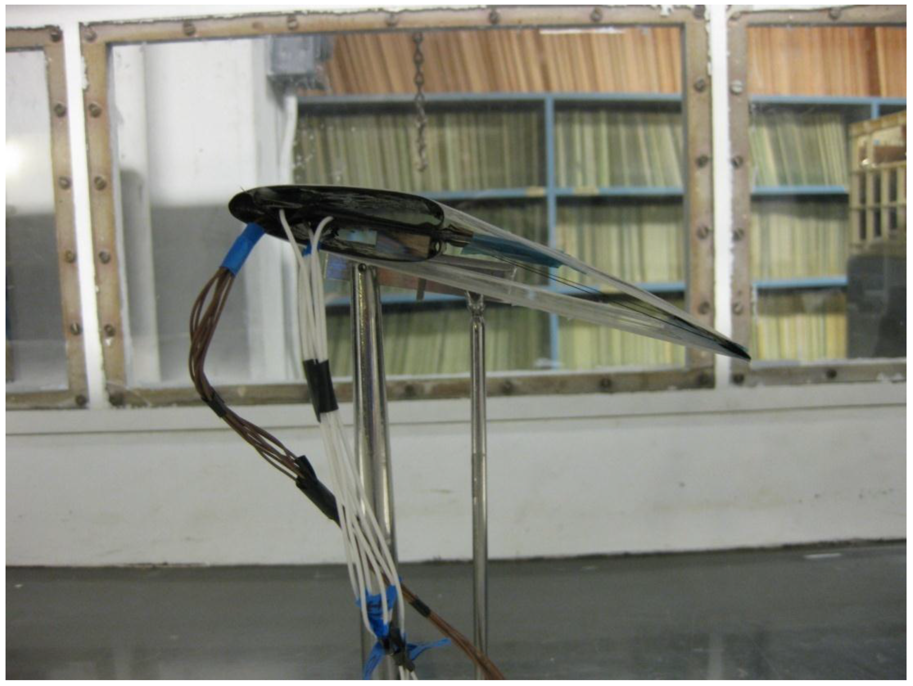
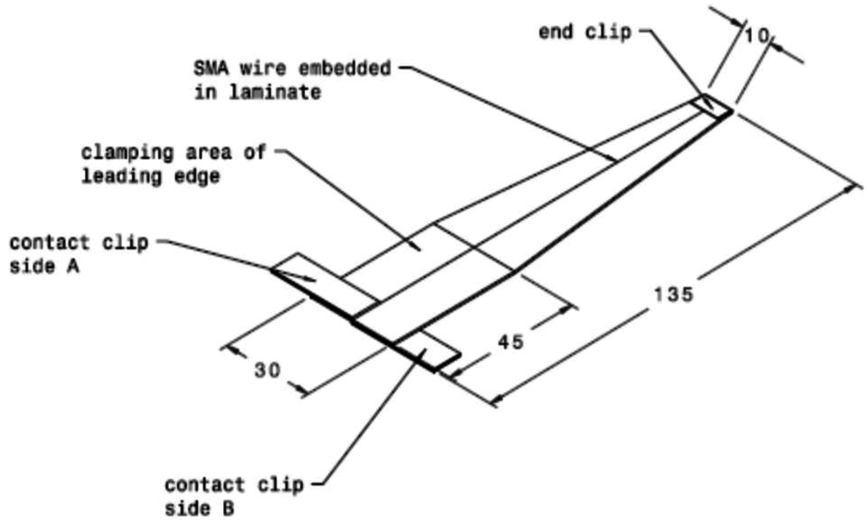
2. SMAPBP Actuator
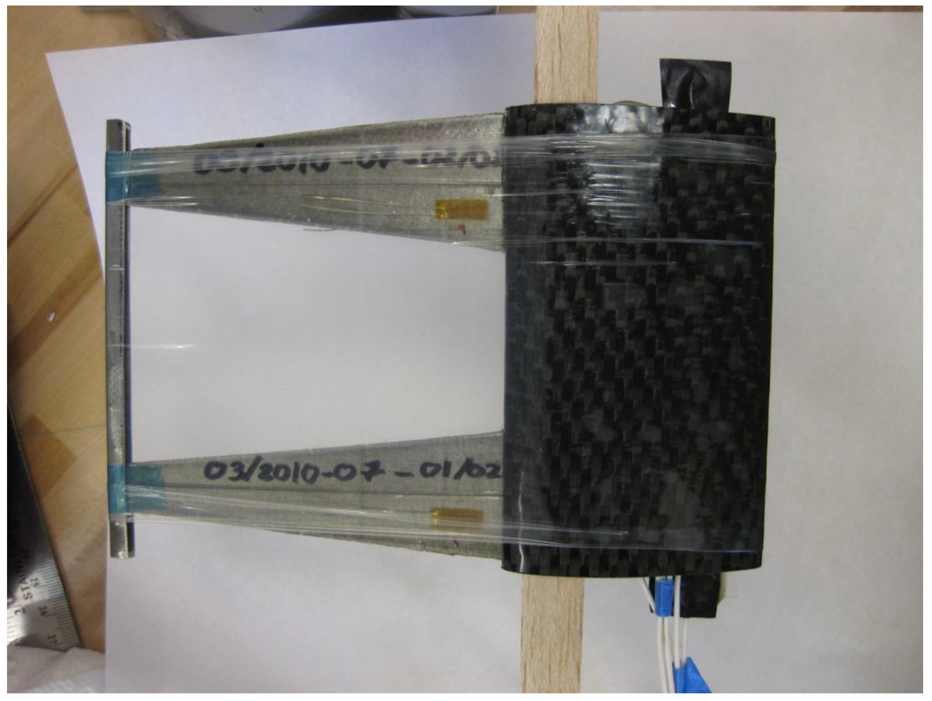
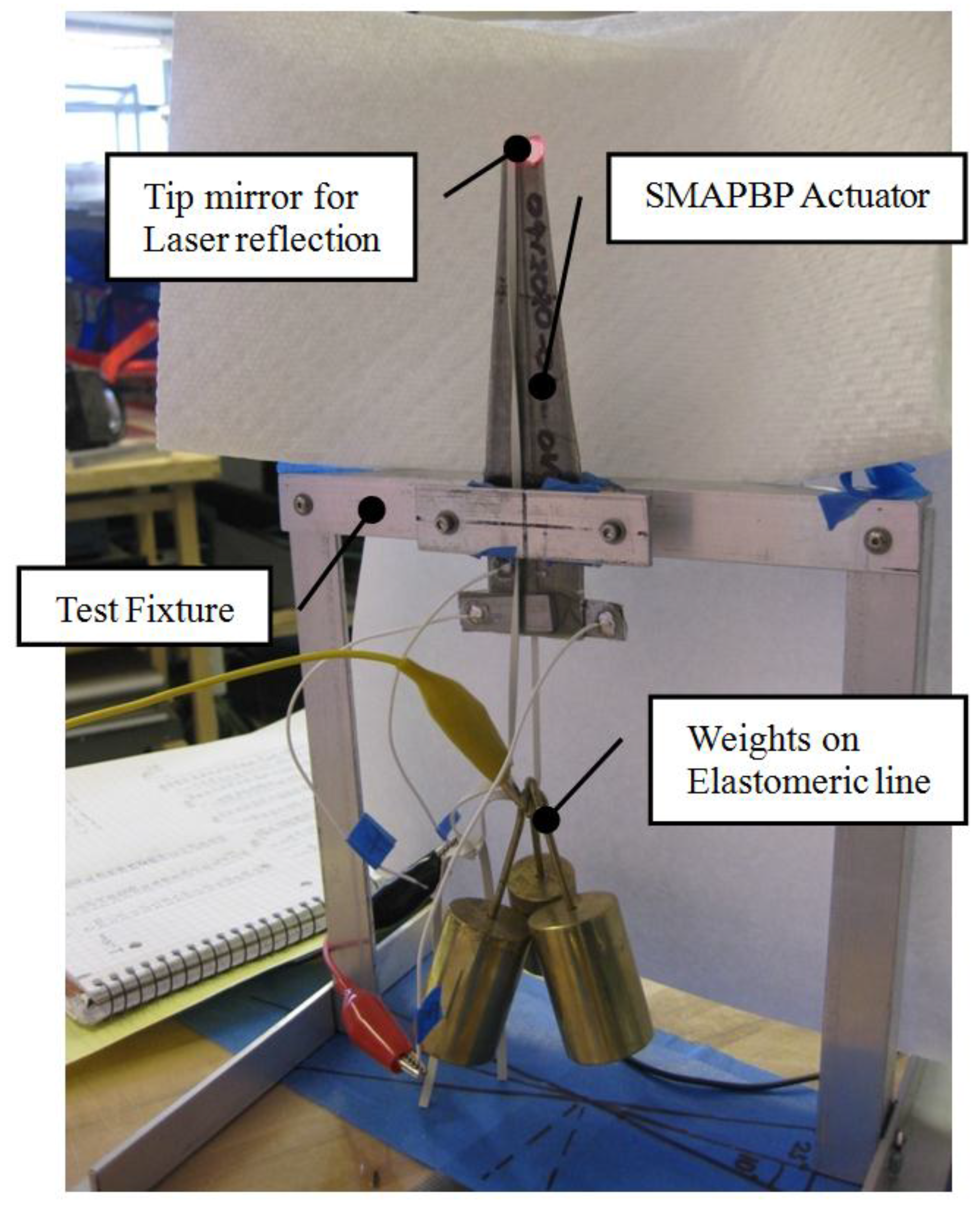
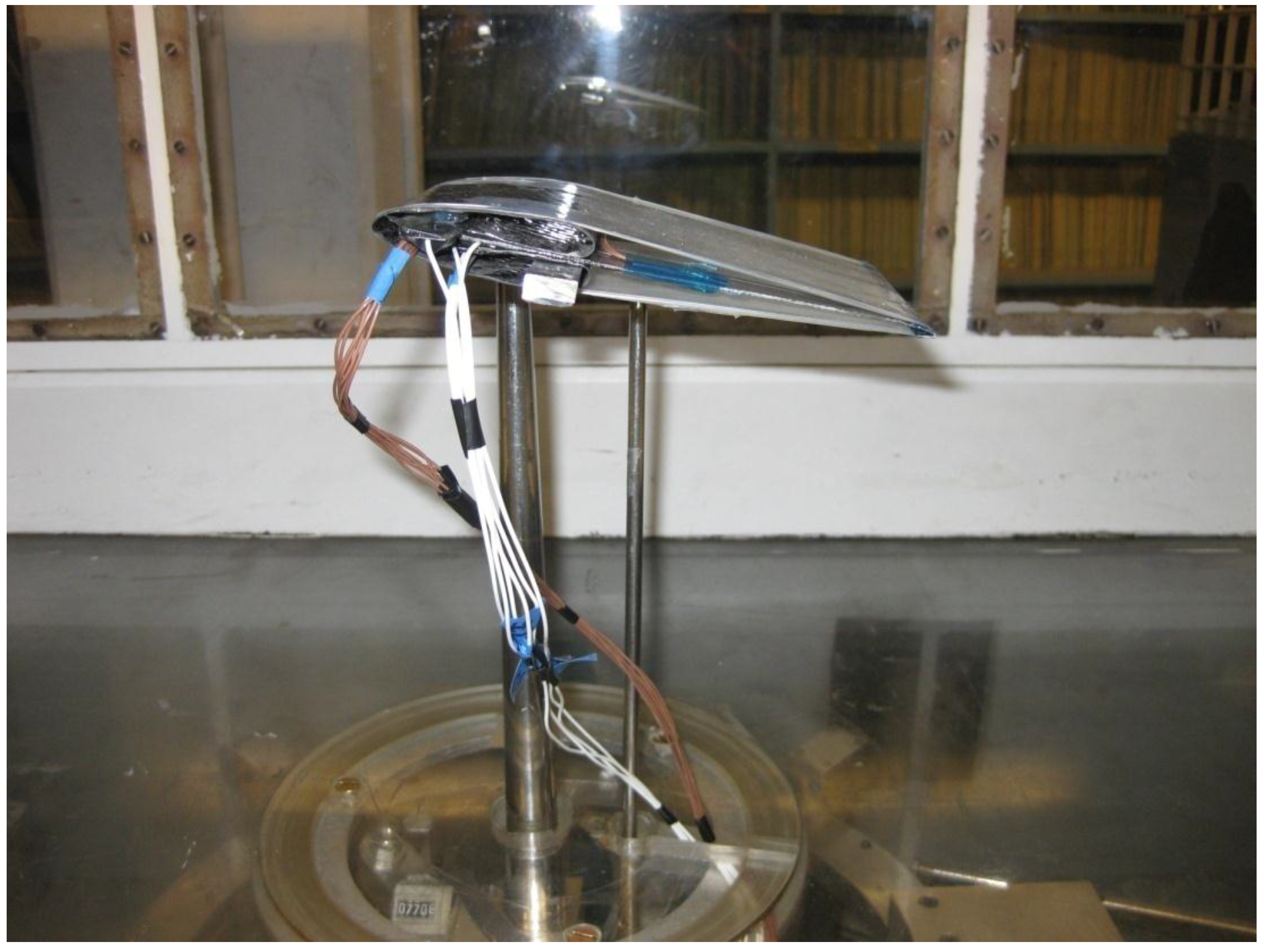
2.1. Experimental Set-Up
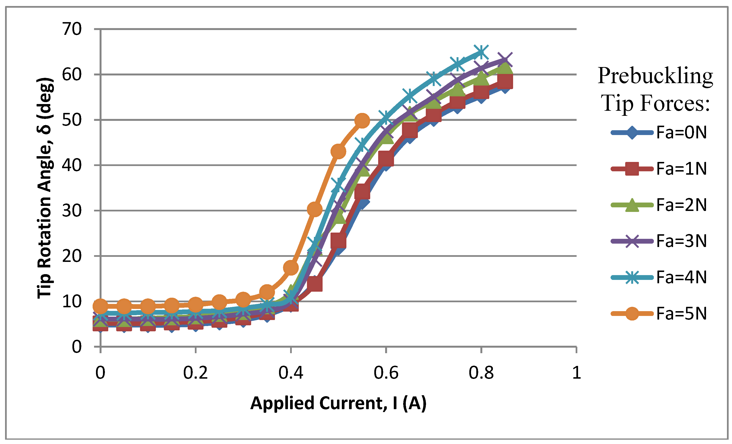
2.2. Results
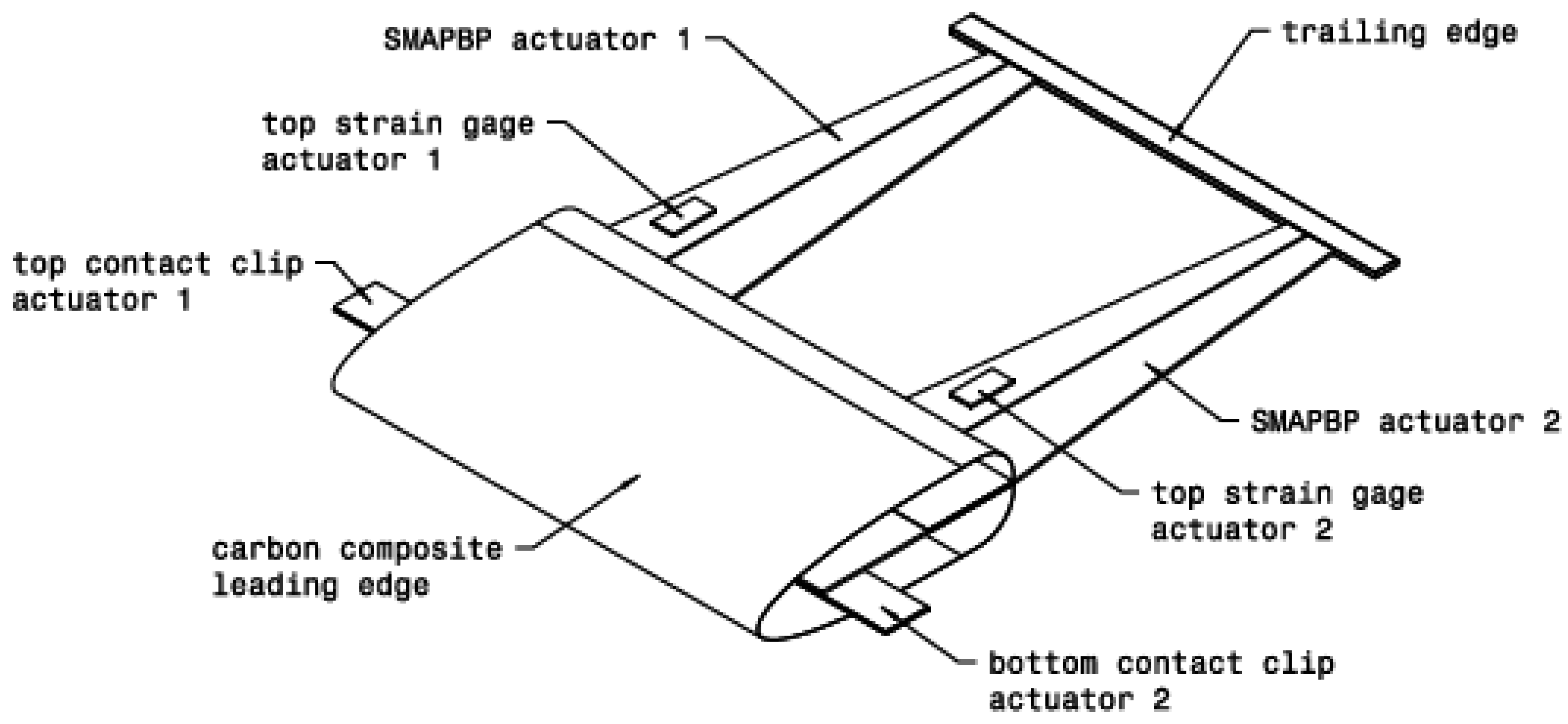
3. Airfoil


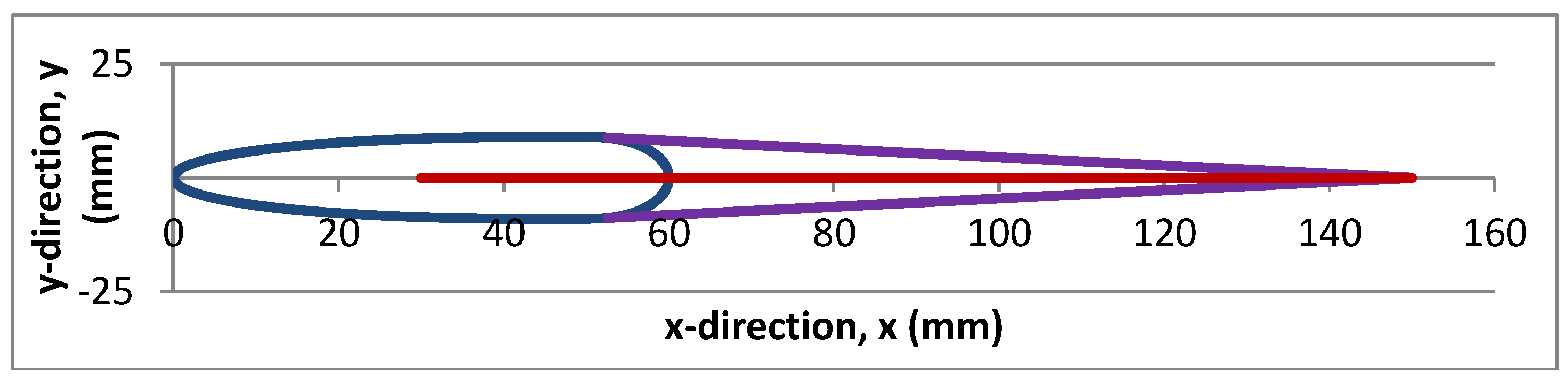
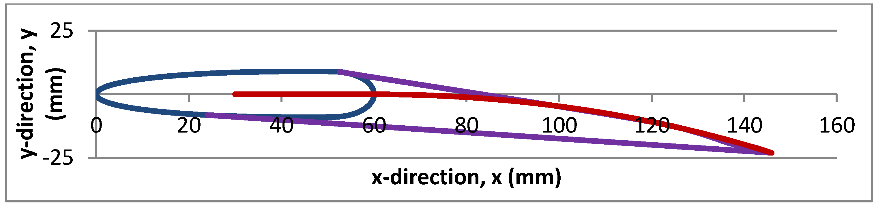
3.1. Adaptive Shape Change of Airfoil


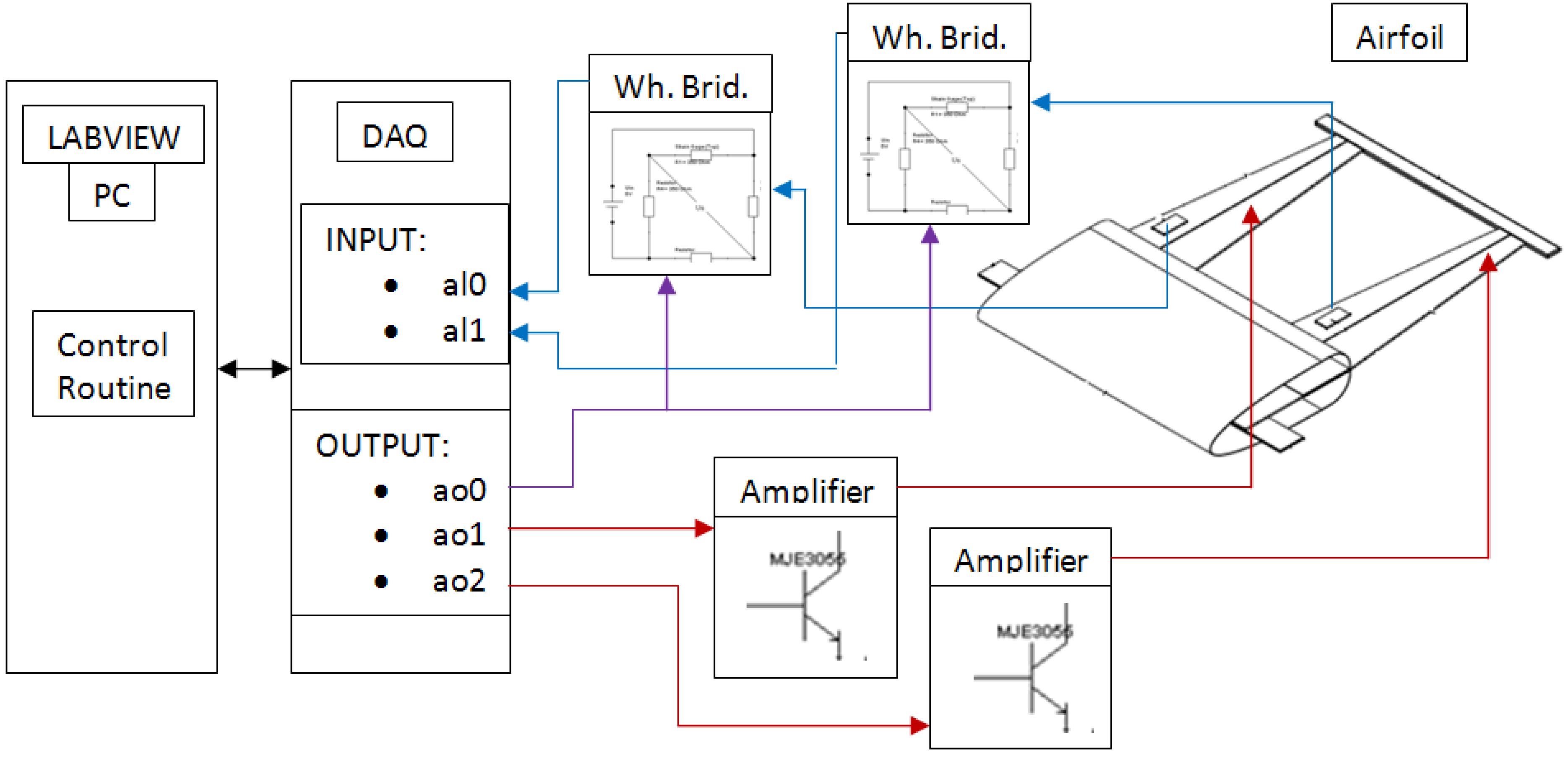
3.2. Active Position Feedback System
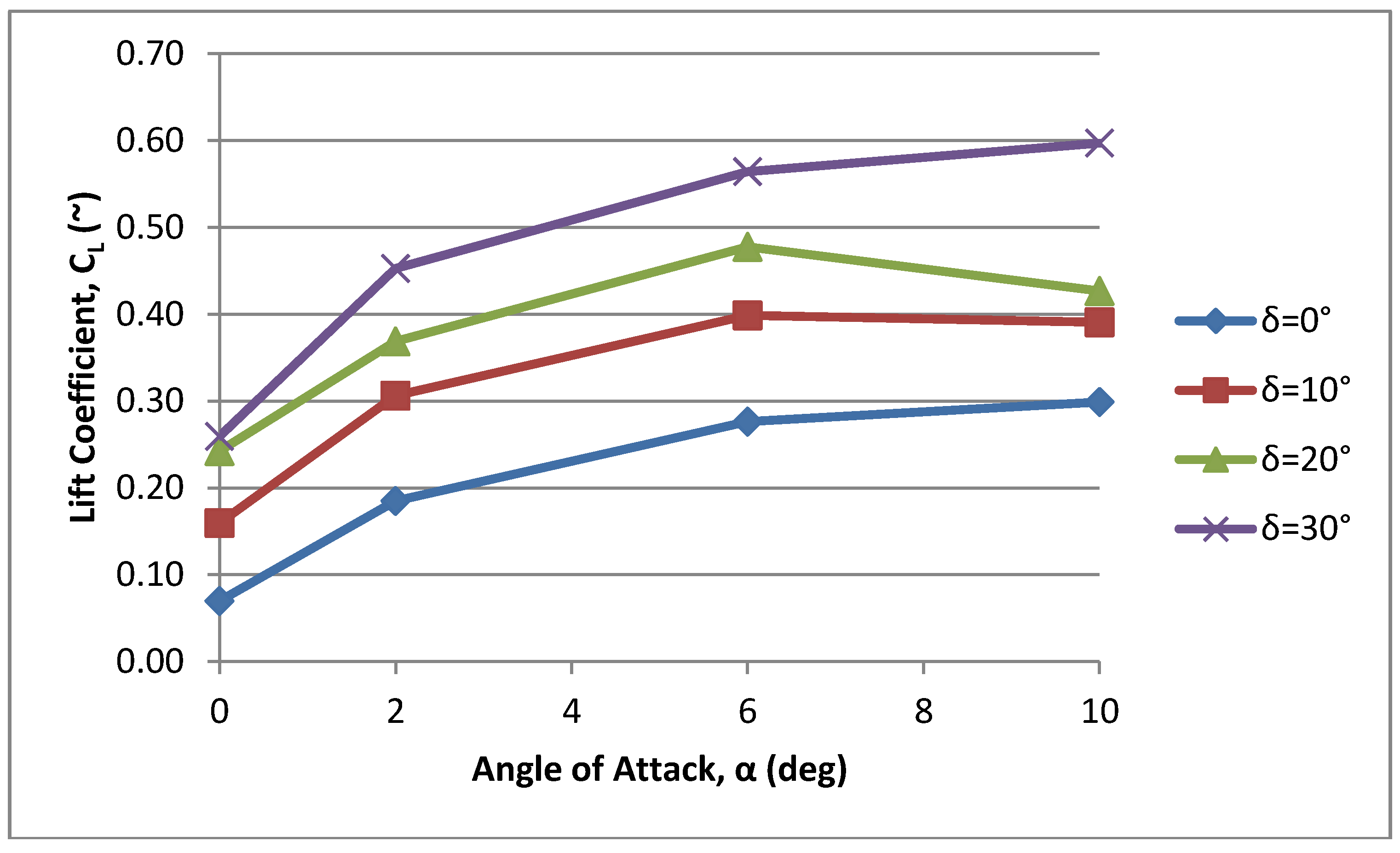
3.3. Wind Tunnel Tests

4. Conclusions
Acknowledgments
Author Contributions
Conflicts of Interest
References
- Crawley, E.; Lazarus, K.; Warkentin, D. Embedded actuation and processing in intelligent materials. In Proceedings of the 2nd International Workshop on Composite Materials and Structures for Rotorcraft, Troy, NY, USA, 14–15 September 1989.
- Lazarus, K.; Crawley, E. Multivariable active lifting surface using strain actuation: analytical and experimental results. In Proceedings of the Third International Conference on Adaptive Structures, San Diego, CA, USA, 9–11 November 1992.
- Lazarus, K.; Crawley, E.; Bohlmann, J.D. Static aerolastic control using strain actuated adaptive structures. J. Intell. Mater. Syst. Struct. 1991, 2, 386–410. [Google Scholar] [CrossRef]
- Spangler, R.L.; Hall, S.R. Piezoelectric actuators for helicopter rotor control. In Proceedings of the 31st Structures, Structural Dynamics and Materials Conference, Long Beach, CA, USA, 2–4 April 1990.
- Barrett, R. Intelligent rotor blade actuation through directionally attached piezoelectric crystals. In Proceedings of the 46th AHS National Conference and Forum, Washington, DC, USA, 21–23 May 1990.
- Barrett, R. Intelligent Rotor Blade and Structures Development using Piezoelectric Crystals. Master’s Thesis, the UM, College Park, MD, USA, 1990. [Google Scholar]
- Barrett, R. Method and Apparatus for Sensing and Actuating in a Desired Direction. U.S. Patent 5,440,193, August 1995. [Google Scholar]
- Barrett, R. Actuation strain decoupling through enhanced directional attachment in plates and aerodynamic surfaces. In Proceedings of the First European Conference on Smart Structures and Materials, Glasgow, UK, 12–14 May 1992; pp. 383–386.
- Ehlers, S.M.; Weisshaar, T.A. Static Aeroelastic Behavior of an Adaptive Laminated Piezoelectric Composite Wing. In Proceedings of the 31st Structures, Structural Dynamics, and Materials Conference, Long Beach, CA, USA, 2–4 April 1990; pp. 1611–1623.
- Ehlers, S.M.; Weisshaar, T.A. Adaptive wing flexural axis control. In Proceedings of the Third International Conference on Adaptive Structures, San Diego, CA, USA, 9–11 November 1992.
- Ehlers, S.M.; Weisshaar, T.A. Effects of material properties on static aerolastic control. In Proceedings of the 33rd Structures, Structural Dynamics and Materials, Dallas, TX, USA, 13–15 April 1992.
- Barrett, R. Active plate and missile wing development using dap elements. AIAA J. 1994, 32, 601–609. [Google Scholar] [CrossRef]
- Barrett, R. Active plate missile development using EDAP elements. J. Smart Mater. Struct. 1992, 1, 214226. [Google Scholar] [CrossRef]
- Barrett, R. Active composite torque-plate fins for subsonic missiles. In Proceedings of the Dynamic Response of Composite Structures Conference, New Orleans, LA, USA, 20 August–1 September 1993.
- Barrett, R. Advanced low-Cost Smart Missile Fin Technology Evaluation; Report to the USAF Armament Directorate, Eglin Air Force Base: Eglin, FL, USA, 1993. [Google Scholar]
- Barrett, R.; Brozoski, F.; Gross, R.S. Design and testing of a subsonic all-moving adaptive flight control surface. AIAA J. 1997, 35, 1217–1219. [Google Scholar] [CrossRef]
- Barrett, R.; Brozoski, F. Missile flight control using active flexspar actuators. J. Smart Mater. Struct. 1996, 5, 121–128. [Google Scholar] [CrossRef]
- Barrett, R. Active aeroelastic tailoring of an adaptive flexspar stabilator. J. Smart Mater. Struct. 1996, 5, 723–730. [Google Scholar] [CrossRef]
- Barrett, R. Invention and Evaluation of the Barrel Launched Adaptive Munition (BLAM); Final report for USAF contract no. F-49620-93-C-0063, USAF Wright Laboratory Flight Vehicles Branch: Wright-Patterson AFB, OH, USA, 1995. [Google Scholar]
- Barrett, R.; Stutts, J. Barrel-Launched Adaptive Munition BLAM Experimental Round Research; Final report for USAF contract no. F-49620-93-C-0063, USAF Wright Laboratory Flight Vehicles Branch: Wright-Patterson AFB, OH, USA, 1997. [Google Scholar]
- Winchenbach, G. Cone Aerodynamic Test; Aeroballistic Research Facility Ballistic Spark Range Technical Report; USAF Wright Laboratory Flight Vehicles Branch: Wright-Patterson AFB, OH, USA, 1996. [Google Scholar]
- Barrett, R.; Stutts, J. Modelling, Design and testing of a barrell-launched adaptive munition. In Proceedings of the 4th Annual SPIE Symposium on Smart Structures and Materials, San Diego, CA, USA, 3–6 March 1997.
- Barrett, R. Design, Construction and Testing of a Prrof-of-Cncept Smart Compressed Reversed Adaptive Munition; SCRAM Report, Final Report to the USAF Armament Directorate, Wright Laboratory: Eglin AFB, FL, USA, 1996. [Google Scholar]
- Barrett, R.; Stutts, J. Development of a piezoceramic flight control surface actuator for highly compressed munitions. In Proceedings of the 39th Structures, Structural Dynamics and Materials Conference, Long Beach, CA, USA, 20–23 April 1998.
- Barrett, R. Construction and Test Report for a Rotationally Active Linear Actuator (RALA) Adaptive Canard; Final Report for McDonnell Douglas: St. Louis, MO, USA, 1997. [Google Scholar]
- Knowles, G.; Barrett, R.; Valentino, M. Self-contained high authority control of miniature flight control systems for aera dominace. In Proceedings of the SPIE 11th International Symposium on Smart Structures and Materials, San Diego, CA, USA, 14–18 March 2004.
- Lee, G. Range-Extended Adaptive Munition (REAM); Final Report from Lutronix Corporation to the DARPA: Del Mar, CA, USA, 1999.
- Lee, G. 40/50 Caliber Range-Extended Adaptive Munition (REAM); Final Report from Lutronix Corporation to the US Army TACOM-ARDEC: Del Mar, CA, USA, 2000.
- Rabinovitch, O.; Vinson, J.R. On the design of piezoelectric smart fins for flight vehicles. J. Smart Mater. Struct. 1993, 12, 686–695. [Google Scholar] [CrossRef]
- Barrett, R. High Bandwith Electric Rotor Blade Actuator Study; Phase I SBIR proposal submitted to the U.S. Army Aviation System Command: St. Louis, MO, USA, 27 June 1992.
- Barrett, R.; Stutts, J. Design and testing of a 1/12th scale solid state adaptive rotor. J. Smart Mater. Struct. 1997, 6, 686–695. [Google Scholar] [CrossRef]
- Barrett, R.; Frye, P.; Schliesman, M. Design, constructionand characterization of a flightworty piezoelectric solid state adaptive rotor. J. Smart Mater. Struct. 1998, 7, 422–431. [Google Scholar] [CrossRef]
- Lee, G. Design and Testing of the Kolibri Vertical Take-Off and Landing Micro Aerial Vehicle; Final report to the Department of Defense CounterDrug Technology Office: Washington, DC, USA, 1997.
- Barrett, R.; Howard, N. Adaptive aerostructures for subscale aircraft. In Proceedings of the 20th Southeastern Conference on Theoretical and Applied Mechanics, Pine Mountains, GA, USA, 17 April 2000.
- Lesieutre, G.A.; Davis, C.L. Can a Coupling Coefficient of a Piezoelectric Actuator be Higher than its Active Material? J. Intell. Mater. Syst. Struct. 1997, 8, 859–867. [Google Scholar] [CrossRef]
- Lesieutre, G.A.; Davis, C.L. Transfer Having a Coupling Coefficient Higher than its Active Material. U.S. Patent 6,236,143, 22 May 2001. [Google Scholar]
- Barrett, R.; Tisco, P. PBP Adaptive Actuator Device and Embodiments. International Patent Application Number PCT/NL2005/000054; via TU Delft, 18 February 2005. [Google Scholar]
- Barrett, R.; Vos, R.; Tisco, P.; De Breuker, R. Post-Buckled Precompressed (PBP) Actuators: Enhancing VTOL Autonomous High Speed MAVs. In Proceedings of the 13th AIAA/ASME/AHS Adaptive Structures Conference, Austin, TX, USA, 18–21 April 2005.
- Vos, R.; De Breuker, R.; Barrett, R.; Tisco, P. Morphing Wing Flight Control via Post-Buckled Precompressed Piezoelectric Actuators. AIAA J. Aircr. 2007, 44, 1060–1068. [Google Scholar] [CrossRef]
- Barrett, R.; McMurtry, R.; Vos, R.; Tisco, P.; De Breuker, R. Post-Buckled Precompressed Pieyoelectric Flight Control Actuator Design, Development and Demonstration. J. Smart Mater. Struct. 2006, 15, 1323–1331. [Google Scholar] [CrossRef]
- De Breuker, R.; Vos, R.; Barrett, R.; Tisco, P. Nonlinear Semi-Analytical Modeling of Post-Buckled Precompressed (PBP) Piezoelectric Actuators for UAV Flight Control. In Proceedings of the 47th AIAA/ASME/ASCE/AHS/ASC Structures, Structural Dynamics and Materials Conference 14th AIAA/ASME/AHS Adaptive Structures Conference, Newport, RI, USA, 1–4 May 2006.
- Van Schravendijk, M.; Groen, M.; Vos, R.; Barrett, R. Closed Loop Control for High Bandwidth, High Curcature Post-Buckled Precompressed Actuators. In Proceedings of the 50th AIAA/ASME/ASCE/AHS/ASC Structures, Structural Dynamics, and Materials Conference 17th AIAA/ASME/AHS Adaptive Structures Conference 11th AIAA No, Palm Springs, CA, USA, 4–7 May 2009.
- Arrieta, A.F.; Bilgen, O.; Friswell, M.I.; Hagedorn, P. Passive load alleviation bi-stable morphing concept. AIP Adv. 2012, 2. [Google Scholar] [CrossRef]
- Bilgen, O.; Friswell, M.I. Implementation of a Continuous-Inextensible-Surface Piezocomposite Airfoil. J. Aircr. 2013, 50, 508–518. [Google Scholar] [CrossRef]
- Friswell, M.I.; Ali, S.F.; Bilgen, O.; Adhikari, S.; Lees, A.W.; Litak, G. Nonlinear Piezoelectric Vibration Energy Harvesting from an Inverted Cantilever Beam with Tip Mass. J. Intell. Mater. Syst. Struct. 2012, 23, 1505–1521. [Google Scholar] [CrossRef]
- Arrieta, A.F.; Bilgen, O.; Friswell, M.I.; Hagedorn, P. Morphing dynamic control for bi-stable composites. J. Intell. Mater. Syst. Struct. 2012. [Google Scholar] [CrossRef]
- Bilgen, O.; Butt, L.M.; Day, S.R.; Sossi, C.A.; Weaver, J.P.; Wolek, A.; Mason, W.H.; Inman, D.J. A Novel Unmanned Aircraft with Solid-State Control Surfaces: Analysis and Flight Demonstration. J. Intell. Mater. Syst. Struct. 2012. [Google Scholar] [CrossRef]
- Borowiec, M.; Litak, G.; Friswell, M.I.; Ali, S.F.; Adhikari, S.; Lees, A.W.; Bilgen, O. Energy Harvesting in Piezoelastic Systems Driven by Random Excitations. Int. J. Struct. Stab. Dyn. 2012. [Google Scholar] [CrossRef]
- Arrieta, A.F.; Bilgen, O.; Friswell, M.I.; Hagedorn, P. Modeling and configuration control of multi-stable piezoelectric composites. Smart Mater. Struct. 2013. submitted for publication. [Google Scholar]
- Bilgen, O.; Wang, Y.; Inman, D.J. Electromechanical Comparison of Cantilevered Beams with Multifunctional Piezoceramic Devices. Mechan. Syst. Signal Process. 2012, 27, 763–777. [Google Scholar] [CrossRef]
- Karami, M.A.; Bilgen, O.; Inman, D.J.; Friswell, M.I. Experimental and Analytical Parametric Study of Single Crystal Unimorph Beams for Vibration Energy Harvesting. Trans. Ultrason. Ferroelectr. Freq. Control 2011, 58, 1508–1520. [Google Scholar] [CrossRef] [PubMed]
- Bilgen, O.; Inman, D.J.; Friswell, M.I. Theoretical and Experimental Analysis of Hysteresis in Piezocomposite Airfoils Using the Classical Preisach Model. J. Aircr. 2011, 48, 1935–1947. [Google Scholar] [CrossRef]
- Barbarino, S.; Bilgen, O.; Ajaj, R.M.; Friswell, M.I.; Inman, D.J. A Review of Morphing Aircraft. J. Intell. Mater. Syst. Struct. 2011, 22, 823–877. [Google Scholar] [CrossRef]
- Bilgen, O.; Karami, M.A.; Inman, D.J.; Friswell, M.I. The Actuation Characterization of Cantilevered Unimorph Beams with Single Crystal Piezoelectric Materials. Smart Mater. Struct. 2011, 20. [Google Scholar] [CrossRef]
- Bilgen, O.; De Marqui Junior, C.; Kochersberger, K.B.; Inman, D.J. Macro-Fiber Composite Actuators for Flow Control of a Variable Camber Airfoil. J. Intell. Mater. Syst. Struct. 2011, 22, 81–91. [Google Scholar] [CrossRef]
- Bilgen, O.; Kochersberger, K.B.; Inman, D.J.; Ohanian, O.J. Macro-Fiber Composite Actuated Simply-Supported Thin Morphing Airfoils. Smart Mater. Struct. 2010, 19. [Google Scholar] [CrossRef]
- Bilgen, O.; Erturk, A.; Inman, D.J. Analytical and Experimental Characterization of Macro-Fiber Composite Actuated Thin Clamped-Free Unimorph Benders. J. Vib. Acoust. 2010, 132. [Google Scholar] [CrossRef]
- Bilgen, O.; Kochersberger, K.B.; Inman, D.J.; Ohanian, O.J. Novel, Bi-Directional, Variable Camber Airfoil via Macro-Fiber Composite Actuators. J. Aircr. 2010, 47, 303–314. [Google Scholar] [CrossRef]
- Bilgen, O.; De Marqui Junior, C.; Kochersberger, K.B.; Inman, D.J. Piezoceramic Composite Actuators for Flow Control in Low Reynolds Number Airflow. J. Intell. Mater. Syst. Struct. 2010, 21, 1201–1212. [Google Scholar] [CrossRef]
- Dynalloy, I. Flexinol™ Technical Data. Available online: http://www.robotshop.com/media/files/pdf/flexinol-technical-data.pdf (accessed on 27 July 2015).
- Ladson, C.L.; Brooks, C.W., Jr.; Hill, A.S.; Sproles, D.W. Computer program to obtain ordinates for NACA airfoils. In NASA Technical Memorandum. Available online: http://ntrs.nasa.gov/archive/nasa/casi.ntrs.nasa.gov/19970008124.pdf (accessed on 27 July 2015).
© 2015 by the authors; licensee MDPI, Basel, Switzerland. This article is an open access article distributed under the terms and conditions of the Creative Commons Attribution license (http://creativecommons.org/licenses/by/4.0/).
Share and Cite
Sinn, T.; Barrett, R. Design, Manufacturing and Test of a High Lift Secondary Flight Control Surface with Shape Memory Alloy Post-Buckled Precompressed Actuators. Actuators 2015, 4, 156-171. https://doi.org/10.3390/act4030156
Sinn T, Barrett R. Design, Manufacturing and Test of a High Lift Secondary Flight Control Surface with Shape Memory Alloy Post-Buckled Precompressed Actuators. Actuators. 2015; 4(3):156-171. https://doi.org/10.3390/act4030156
Chicago/Turabian StyleSinn, Thomas, and Ron Barrett. 2015. "Design, Manufacturing and Test of a High Lift Secondary Flight Control Surface with Shape Memory Alloy Post-Buckled Precompressed Actuators" Actuators 4, no. 3: 156-171. https://doi.org/10.3390/act4030156