1. Introduction
An electrorheological fluid (ERF) is a suspension with non-conducting particles that increases its viscosity when subjected to an electric field (E-field). When exposed to an E-field, the ERF forms viscoelastic chemical bonds, which results in increased viscosity. To make an ERF useful, the fluid is made to flow between two parallel electrode surfaces separated by a gap where an E-field is applied, so that the electrorheological (ER) effect can be activated. For this reason, the geometry and the arrangement of the electrodes are important, because they dictate the maximum yield stress achievable for a specified E-field. Given a high enough E-field, the ERF turns into a Bingham plastic that blocks the flow of the fluid and effectively acts as a valve [
1].
Figure 1 shows how inducing an E-field causes the ER effect to occur between two electrode plates.
Figure 1.
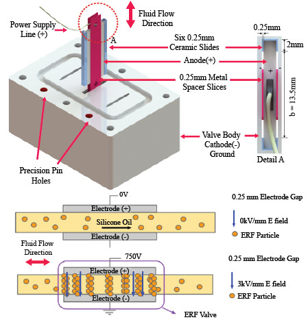
Electrorheological fluid (ERF) flows between two electrode plates. (a) The configuration has no potential across the electrodes, while (b) the configuration has 750 V of voltage potential across a 0.25-mm gap, which is an electric field (E-field) of 3 kV/mm.
Figure 1.
Electrorheological fluid (ERF) flows between two electrode plates. (a) The configuration has no potential across the electrodes, while (b) the configuration has 750 V of voltage potential across a 0.25-mm gap, which is an electric field (E-field) of 3 kV/mm.
Figure 1a shows that, since there is no voltage applied on the electrodes, there is no E-field between the plates, and so, the ERF flows as a regular viscous fluid through the plates.
Figure 1b shows that 750 V is applied on the electrode. Thus, for a 0.25-mm gap, a 3-kV/mm E-field is present between the plates, and the electrorheological (ER) effect is activated. The fluid between the plates has a higher apparent viscosity, which is proportional to the influence of the E-field. If the yield stress is high enough, the plates can act as a valve that stops fluid flow. The pair of electrode plates described in
Figure 1 will now be referred to as an ERF valve.
The exotic property of ERF has many applications. Until now, most applications for ERF have only required low-torques, such as tactile sensing and haptic feedback [
2,
3,
4,
5,
6,
7,
8]. Recently, researchers and the industry have been exploring ERFs for resistive applications [
9,
10,
11,
12,
13,
14,
15,
16,
17]. In particular, recently, the research community has only performed ERF application studies on brakes [
9], clutches [
10], dampers [
11,
13,
14,
15,
16,
17] and haptic devices [
6,
7,
8,
18]. However, a key missing capability is to use ERF as a torque-source actuator, which provides positive work on an external system. This paper is motivated towards creating the first ERF-based rotary hydraulic actuator. Such an actuator will require an ERF-based valve, and thus, this paper performs an extensive study on an ERF valve designed to be used as part of an ERF actuator.
Sheng
et al. have performed studies on using ERFs as valves [
19], and others have used the ERF as a micro-valve [
20,
21], confirming the pressure drop properties discussed in
Section 2.1. Note that these studies have only confirmed the basic functionality of using an ERF as a valve, and there is still a lack of empirical study in the literature that utilizes the ERF valve as part of an overall system in which nonlinear effects, such as particle distribution temperature and ERF particle purity, can play a big role in the performance of an ERF valve and are only observable through experimentation. This paper also reports the effects of temperature on arcing stability and particle distribution on performance stability through testing the ERF valve under different flow conditions.
Until now, the ERF has not been used as a hydraulic actuator, because of its low 8-kPa theoretical upper bound yield stress [
22] that would result in an impractically large actuator. The reason for such a low yield stresses is that high E-fields applied to prior ERF formulations cause the valve to electrically short itself between the electrode plates. This phenomena, called arcing, renders the ERF unusable and unsalvageable [
23,
24]. However, with the recent development of the giant electrorheological fluid (GER) [
25] with yield stresses of 130 kPa, the creation of an ERF-based actuator is now within the realm of practicality. This paper takes an initial step towards a practical actuator by characterizing a new ERF valve meant for actuation.
Overall, the long-term objective is to create the first ERF-based hydraulic rotary actuator that provides positive work. A proposed ERF actuator is presented in
Section 2.2. While Vitrani
et al. have performed torque control experiments with an ERF actuator [
3], it still acts as a torque-controlled clutch that resists motion and not as an actuator that provides positive work. Consequently, their device is only useful for haptic feedback or damping applications.
One strong motivation for creating an ERF-based hydraulic actuator is that the operation does not need a mechanically-actuated valve, since an ERF valve is only composed of electrode plates that can be integrated into the actuator body. Current hydraulic actuators use high-precision mechanical fluid valves, which are very expensive, have long lead times and limited lifetimes due to wear. However, because the valves for the ERF actuator are not mechanical, an ERF-based hydraulic actuator can theoretically have a longer operational life and cost less.
Given the potential benefits of an ERF-based actuator, understanding an ERF valve is imperative. Current models show that the geometry of the ERF valve, the fluid’s viscosity and the ERF’s yield stress properties dictate the achievable pressure drop across the valve [
26], which predicts its performance. To understand and create better ERF valves, here, the following are presented: (1) design considerations for an ERF actuator; (2) a new design of an ERF valve; (3) a new method to obtain ERF viscosity and yield characteristics; and (4) the results of these measurements and the design insights they provide.
The ERF used in this study was GER STD 0201, developed by Smart Materials Laboratory (SML) [
27]. The manufacturers have specified the following rated properties: The GER STD 0201 has a yield stress of 100 kPa at 5 kV/mm using the Bingham model, a dynamic viscosity of 2.0 Pa-s and an average response time of less than 3 ms [
28]. Note that the dynamic viscosity properties were obtained by averaging high flow velocities, and the yield stresses were obtained after activating the ERF and placing a load. These test conditions do not accurately reflect the operating conditions of an ERF actuator, and for this reason, this paper’s experiments remeasure the dynamic viscosity of the ERF under very low flow conditions and remeasure the yielding properties of the ERF while there is a very high fluid flow.
For this study, a new test-bed for measuring ERF characteristics at low flow rates was developed. Operating at low flow rates is important, since it allows ERF actuators to perform slow movements. Existing methods, which use viscometers and rheometers, do not properly measure fluid properties at low fluid flow rates, because these tools can only measure the static viscosity of ERF at a specific range of fluid flow speed, which is typically at higher flow velocities due to the high surface tension of ERF. Thus, these tools have low flow rate measurements that are noisy and inaccurate. Yongliang
et al. used a high-end rheometer, but it can only operate at fluid flow rates as low as 0.5 L/min [
12,
29], while the proposed test-bed can operate as low as 0.049 L/min, an order of magnitude in improvement. The experiments performed in this study are able to characterize the ERF’s yield stress and viscosity at low flow rates for the first time. Additionally, the experiments also identify how the ERF’s yielding properties change if the ERF is activated while high velocity flows are present.
Cho in 1998 has shown that an oscillating rheometer can obtain the properties of the ERF, but their setup inherently homogenizes the distribution of ERF particles [
30]. An ERF actuator in operation may need to hold its position for long periods of time, and this paper’s experiments show that the distribution of particles gets affected without proper mixture, thereby changing the viscosity of certain regions in the fluid over time. Therefore, it is more practical to measure the viscosity of the ERF inside an operating system. The proposed test-bed can measure dynamic viscosity of an ERF valve in operation as part of an ERF actuator system.
Overall, the paper’s contributions are on measuring the dynamic viscosity of ERF at low flow velocities for the first time and identifying the effects of different flow rates on the yield characteristics of an ERF when it is used to completely block fluid flow. Specifically, it was found that higher flow rates negatively affect yield properties, and lower flow rates are less efficient due to increased power demands.
To obtain the viscosity and yield strength characteristics, the test-bed measures the ERF’s viscosity under no E-field and the ERF’s yield strength characteristics under different flow conditions. When measuring yield strength, the system was tested under two additional conditions. First, a constant flow rate was employed while introducing a variable E-field. Second, a variable flow rate was employed while introducing different fixed E-field values. Calculating viscosity and yield stress properties is a matter of measuring the pressure drop and using the equations presented in
Section 2.1.
The paper is structured as follows. In
Section 2, an analytical model of the ERF is presented, where Equation (
1) will show the relationship between the pressure drop, ERF valve geometrical parameters and the ERF’s material properties.
Section 2 continues by discussing the architecture of an ERF actuator for practical use, design considerations for using ERFs and the design and manufacturing of an ERF valve for the experiments previously mentioned. In
Section 3, details of the experimental setup are discussed. Finally,
Section 4 presents, analyzes and discusses the results of the effects of different flow conditions on the dynamic viscosity and yield properties experiments, and the paper concludes in
Section 5.
2. Design and Development of an ERF Valve for ERF-Based Actuators
2.1. Analytical Model of the ERF Valve
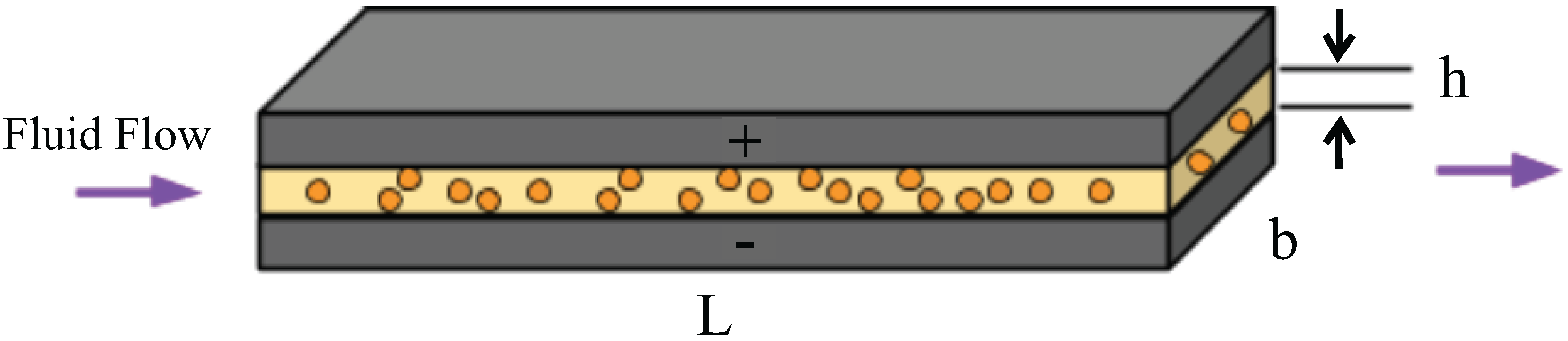
To reliably and predictably create a successful ERF-based hydraulic actuator, it is important that the valve’s geometrical parameters as indicated by
Figure 2 are identified. The pressure drop,
, across the valve can be calculated as follows [
26]:
where
Q is the fluid flow rate,
η is the viscosity of the ERF,
is the yield stress dependent on the E-field,
L is the total length of the valve,
b is the cross-section width of the ERF valve and
h is the constant cross-section gap between the two electrode plates.
Figure 2.
The schematic shows the geometrical parameters of an ERF valve.
Figure 2.
The schematic shows the geometrical parameters of an ERF valve.
Equation (
1) shows that given certain geometrical properties of the ERF valve, under zero E-field and maximum flow,
Q, the yield stress term drops, and the viscosity of the ERF can be calculated. Similarly, given known geometrical properties, under some E-field and no flow, the viscosity term drops, and the ERF’s yield characteristics can be calculated. Both quantities can be calculated by knowing the measured pressure drop across the valve. In the experiments performed in this study, a strain-gauge sensor is used to calculate the pressure difference across the valve.
Thus, substituting
and solving for the viscosity in terms of the other parameters and the measured pressure drop,
, and fluid flow rate,
Q, yields:
Similarly, substituting
and solving for the yield stress, the following can be obtained:
where
is the yield stress that successfully blocks fluid flow for a measured
. In the case that fluid flow is still present, the yield stress at a given E-field can still be calculated, and Equation (
3) will have a non-zero fluid flow term from Equation (
1).
Finally, obtaining the viscosity and yield strength characteristics is a matter of measuring the pressure drop,
, and using Equations (
1), (
2) and (
3).
2.2. Proposed ERF Actuator Architecture
Figure 3 presents an example schematic of a simple hydraulic-based ERF actuator, which uses four ERF valves in an H-bridge configuration to move the output shaft connected to a vane. In
Figure 3a, four ERF valves are arranged in an H-bridge configuration. Similar to the control of electric motors, switching the appropriately labeled valve can dictate the torque and speed of the rotary output of the actuator. In
Figure 3b, a more detailed description of the vane block is shown. High pressure enters on one side of the shoe, which rotates the vane, and low pressure exits the other side of the shoe. Finally,
Figure 3c shows a front view of the different pressure inlets. An example operation could be activating Valves 2 and 3, which fully closes them. Doing so ensures that the high pressure flows through Valve 1, the vane, Valve 4 and back to the fluid reservoir.
Figure 4 gives another schematic on how an assembly of valves can be arranged with a hydraulic vane to construct the actuator. Four ERF valves are located inside the valve H-bridge assembly, and the shaft output assembly can be similar to the design of a hydraulic rotary actuator.
Figure 3.
A schematic representation of an ERF actuator controlled by four ERF valves is presented.
Figure 3.
A schematic representation of an ERF actuator controlled by four ERF valves is presented.
Given this H-bridge architecture, there are two primary ways to control the ERF actuator, which are called sliding voltage control and pulse-width modulation (PWM). These two control techniques are similar to the control of a rotary electric motor. The sliding voltage technique utilizes the ERF’s property to control the pressure drop across the valve by changing the E-field, which changes the yield stress of the ERF, as Equation (
1) predicts. The effect essentially creates a partially-closed valve. However, one big disadvantage is that this method heats up the fluid as energy is dissipated to drop the pressure.
The second control technique uses PWM, which rapidly turns on and off the ERF valve at some specified frequency. Instead of changing the voltage across the electrode plates, the maximum voltage is always applied whenever the ERF valve is turned on. Because it is both partially turned on and turned off at a specified frequency, the effective voltage potential that the valve sees is dependent on the percent duty cycle of the PWM. The average pressure drop becomes proportional to the PWM, and the ERF valve can be controlled. The main positive over the sliding voltage technique is that minimum power is dissipated, since the valve is either fully turned on or off. However, a disadvantage is that the switching rate depends on how fast the ERF can actually form the chains. Preliminary research has claimed that it can have a switching rate of at least 100 Hz, but a higher rate might be necessary for particle actuator applications [
20,
31].
Figure 4.
An ERF valve block and vane block assembly concept schematic is shown.
Figure 4.
An ERF valve block and vane block assembly concept schematic is shown.
2.3. Valve Design Considerations
ERFs with low yield-strength capability have historically prevented the development of ERF-based hydraulic actuators and the ERF. One might propose that any arbitrary yield stress can be achieved by increasing the E-field as needed. For example, reducing the gap distance between the electrode plates increases the E-field and creates stronger ERF bonds, which causes an increase in the operating yield stress of the ERF. However, the E-field can only be so high until the ERF experiences electrical breakdown via electrical arcing. Since an ERF can be modeled as a capacitor in parallel with a leaky resistor [
32], arcing can occur when the ERF shorts itself with a high leak current across the plates due to a high E-field. Unfortunately, this electrical phenomena means that the E-field condition for arcing is largely dependent on the material properties of the ERF. While arcing can be further prevented by operating at lower E-fields, a substantial trade-off is made by not utilizing the maximum yield-strength of the ERF. Additionally, contamination due to conductive particles can also reduce the resistance across the electrode plates, enabling the ERF to arc more easily, since a lower E-field will be needed to short the electrode plates. Lastly, if arcing does not occur due to electrical shorting of conductive particles, air bubbles within the system can also experience an electrical breakdown, causing a chain reaction, which makes the ERF arc, as well. Once arcing occurs, the ERF is permanently destroyed [
23,
24]. To make a useful actuator out of these earlier ERF formulations, the size of the actuator would need to be very big and impractical.
In addition to ERF arcing, sedimentation is another problem designers must face. Because ERF is a suspension fluid, without mixture, sedimentation can occur if the ERF is not mixed occasionally. In an isolated setting where an ERF is in a cylindrical container, simply stirring the ERF will redistribute the ERF particle deposit at the bottom of the container. In this way, it is possible to reuse the ERF even after sedimentation due to long idle storage times. However, if the ERF is in a complex mechanical system, mixture might not be possible.
The quality of ERF is very important to prevent sedimentation. Some ERFs can last for months without mixture, but some can only last for days. In the authors’ experiments with the ERF, both cases have been experienced, and only the quality of the ERF can change the sedimentation time. Once complete sedimentation occurs, the ERF becomes a sticky gel, which sticks to different parts of the system. In addition to replacing the ERF, the entire assembly must be dismantled, and a proper cleaning must be performed.
In terms of the reliability and controllability of the ERF, the stability of its performance under varying temperature is another design concern. Since the ERF is utilized by creating bonds due to an E-field, temperature can either make these bonds stronger or weaker. It is of particular concern if the ERF suddenly loses significant yield stress due to unfavorable temperature conditions [
33]. When the temperature increases, the viscosity of the fluid decreases, and as predicted by Equation (
1), the viscosity change can affect the yield properties of the ERF valve. In this paper’s tests, the ERF temperature varies from 18.5 °C to 22.5 °C. Fortunately, there was no observed significant performance change, and the performance was found to be repeatable and stable in these temperature regions.
ERF also has issues with the particle distribution. If the ERF particles are not in a homogenous mixture, the performance of the ERF will vary across the fluid. Certain regions can be more viscous due to a higher concentration of particles and, consequently, will also have stronger bonds. This can occur, for example, when an ERF actuator needs to maintain a position, all valves are closed and ERF particles are getting stuck near the valve. Similarly, other regions can be diluted, less viscous and form weaker bonds. Due to the uneven particle distribution, Equation (
1) predicts that the pressure drop relationship of the ERF valve will vary, since viscosity and yield strength will not be constant. Therefore, it is important that the ERF is evenly distributed to have a high predictability of performance.
Another issue that designers must face is the mechanical wear of the system due to the ERF. Because the ERF contains particles, the hardness of these particles can cause accelerated wear on the system if the material selection of the parts is not done carefully. For example, some metals are not suitable to be electrode plates, since rusting can occur. The ERF valve must also resist wear, since the changing geometry can affect the predicted pressure drop across the valve and can undermine the performance of the ERF. In general, for any material interacting with the ERF, it is important to consider if the material is ERF compatible, and this may change depending on the composition of the ERF. This compatibility issue makes it difficult to select appropriate pumps, fluid hoses and miscellaneous parts that interact with the fluid.
When sizing the ERF valves, knowing the characteristics of the ERF is very important. The viscosity of the fluid must be known, as it is helpful in predicting the pressure drop across the valve when there is no E-field. Similarly, knowing the maximum yield stress before the breakdown voltage is reached for a given valve gap is also important, as the maximum yield stress dictates the maximum pressure that the ERF valve can block and, therefore, the maximum torque that the ERF actuator can provide.
The frequency response of the ERF is another design concern. Depending on the ERF being used and depending on the E-field the ERF is experiencing, the switching frequency may change. This is true in the case that the ERF is operating with the GER effect. For example, a recent study found that the GER effect can have a lower bandwidth (118 Hz) if the operating E-field is too high [
31]. This suggests that the maximum bandwidth of the GER effect is related to the applied E-field.
In terms of design and manufacturing, maintaining the gap between the electrode plates is the hardest constraint to fulfill. If the gap is not constant, the pressure drop relationship described in Equation (
1) will be different. Namely, the gap will be a function of position, and an integration is necessary to find the true pressure drop. Thus, for simplicity, it is important that in designing, manufacturing and assembling the valve, the final assembly must have a constant gap.
The final considerations apply to standard hydraulic systems, but they are mentioned for completion. Since ERF is a fluid, leakage must be prevented. When using gaskets to combine different components together, equal torque must be applied on all of the screws securing the enclosure to ensure that the gasket is properly engaged in all areas. A gasket at the output shaft of a rotary hydraulic actuator may reduce leakage, but can also reduce performance due to high friction, and a proper sizing of the ERF valves and the actuator body housing the vane is necessary to ensure that the desired torque performance is still achievable.
2.4. ERF Valve Design, Prototype and Fabrication
In
Figure 5a, a perspective view of the valve block shows three slots for an ERF valve. Note that the fluid can flow from top to bottom or
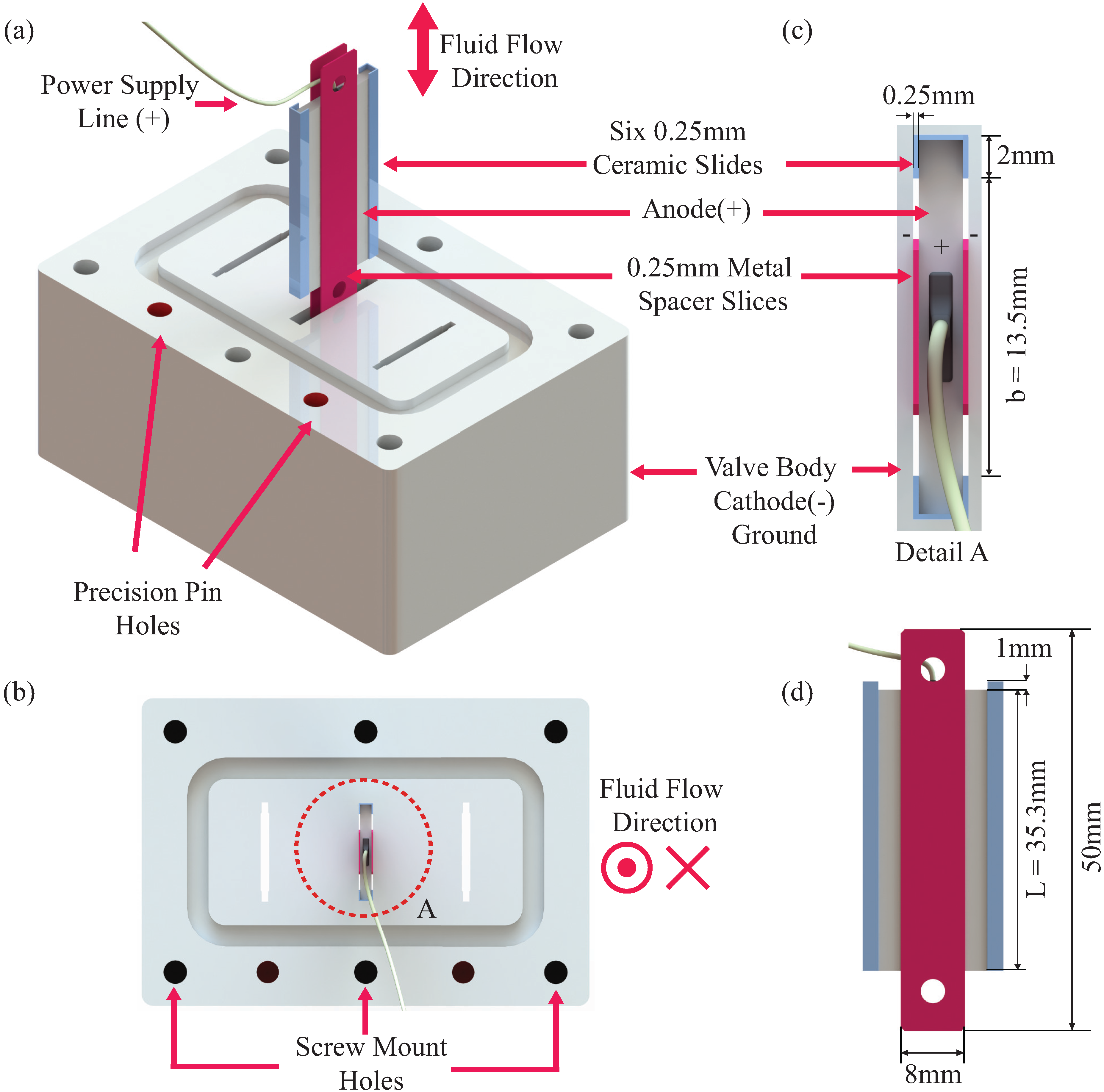
vice versa. Here, only the center slot is utilized, and the other two slots are blocked during testing. The small positive metal anode and the negative valve body cathode are the two main components of the valve. These two components constitute the electrode plates described earlier, and the rest of the components are used to maintain the desired gap between the electrode plates. The metal anode is connected to the positive terminal of the power supply via an epoxied wire, and it is insulated from the valve body using six 0.25-mm ceramic slides. The ceramic slides and the metal anode are kept in place using epoxy as the adhesive. These 0.25-mm ceramic slides were obtained from Suzhou Ceramtec High-tech ceramics Co., Ltd.
Figure 5b shows a top or bottom view of the valve structure. A pocket contour is made for an O-ring gasket, and the holes are used for aligning pins and mounting screws during assembly.
Figure 5c shows a detailed view of the ERF valve anode assembly. The positive anode, powered by the power supply, is the small metal inside the valve body. The negative cathode is the entire metallic body, which is also connected to the common ground of the system. Note that the cathode and anode components are the two metallic electrode plates of the ERF valve, and they are separated by using six insulating 0.25-mm ceramic slides.
Figure 5d shows a side-view of the anode and includes the dimensions of the two 0.25-mm metal spacer slices. Note that the metal spacer is only useful during assembly and is not included in the final valve structure. Lastly, the L and b dimensions indicate the same dimensions described in
Table 1 and
Figure 2.
Figure 5.
A detailed 3D rendering of the ERF valve is shown in multiple views. In (a), a perspective view shows three potential slots for an ERF valve and only the middle slot is utilized. While (c) shows the top view, (b) is a close up of the anode assembly indicating key dimensions such as the 0.25 mm gap. The anode assembly is located using the ceramic slides and fixed in place using epoxy. Finally, (d) shows another view of the anode assembly. Note that the red metal slices are only used to aid with assembly. These are discarded after the anode assembly is fixed in place.
Table 1.
Measured geometrical parameters of the valve.
Table 1.
Measured geometrical parameters of the valve.
| Channel No. | h (mm) | b (mm) | L (mm) |
|---|
| 1 | 0.337 | 13.378 | 35.30 |
| 2 | 0.352 | 12.808 | 35.30 |
During assembly and application of epoxy, the red, 0.25-mm metal slides were used to help maintain the desired 0.25-mm gap of the fluid channels. For manufacturing, the metallic valve body had the valve slot channels cut out using electrical discharge machining (EDM), and the pin holes, mounting holes and gasket pockets were made on a computer numerical control (CNC) mill.
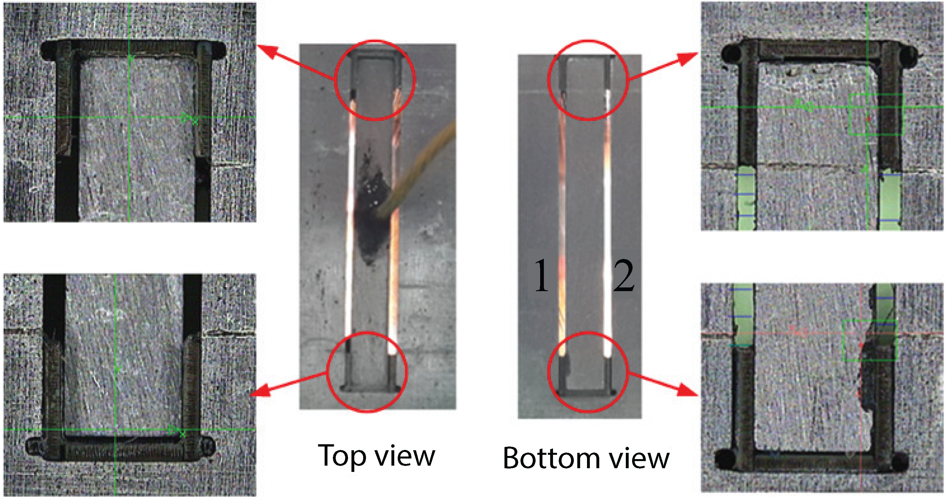
Figure 6 shows the ceramic slides and metallic anode of the ERF valve. The enlarged pictures confirm that both components are well fixed in place. However, during assembly, the application of epoxy was not perfect; thus, Channel 1 and Channel 2 have different gaps. The actual channel size is listed in
Table 1. Those geometrical parameters will be used to calculate the dynamic viscosity of the ERF.
Figure 6.
A closer look at the top and bottom views of the valve’s epoxied ceramic slides and metal anode is shown.
Figure 6.
A closer look at the top and bottom views of the valve’s epoxied ceramic slides and metal anode is shown.
5. Conclusions and Discussions
Recent innovations in discovering the giant ERF effect are enabling the realization of an ERF-based hydraulic actuator. In this paper, a design of a working ERF valve is presented, and its properties are characterized using a new test-bed that obtains more accurate results for low flow rates. The results also give additional design considerations for future ERF-based valves to create a functional ERF-based hydraulic rotary actuator. One insight suggests that due to the difficulty in homogenizing the distribution of ERF particles, feedback using the E-field should be implemented to stabilize the pressure drop across the ERF valve. Without feedback, the pressure drop due to the fluid flowing through the valve will fluctuate, since the viscosity of the fluid varies.
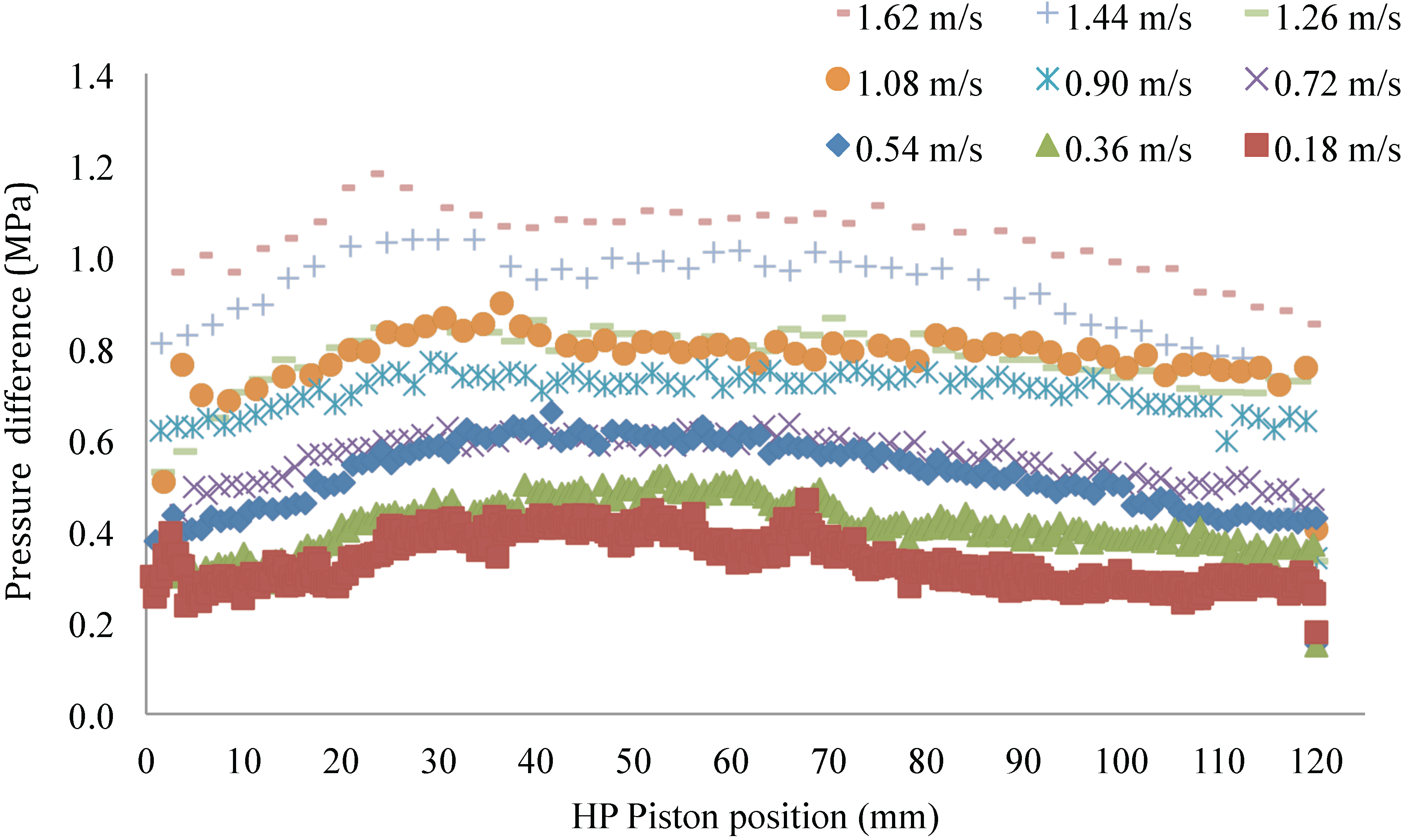
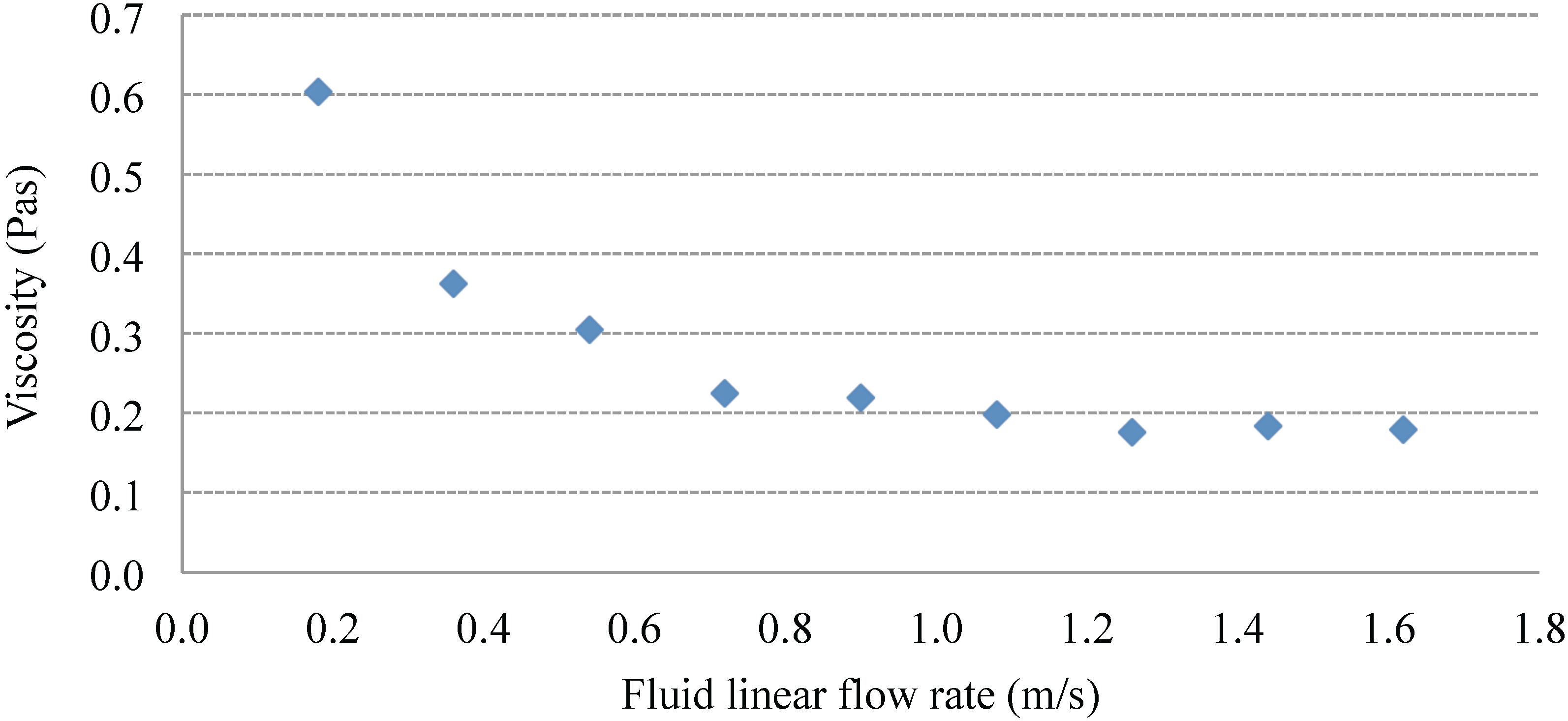
The test-bed also successfully measures the ERF’s dynamic viscosity for flow rates as low as 0.044 L/min, an order of magnitude better than high-end rheometers. For low flow rates, the calculated dynamic viscosity is 0.6 Pa-s and reduces to 0.2 Pa-s for higher flow rates. Since the ERF has a higher viscosity at low flow rates, more power is needed to move the ERF at low flow rates. Thus, efficiency can be increased if the operating region covers higher flow rates.
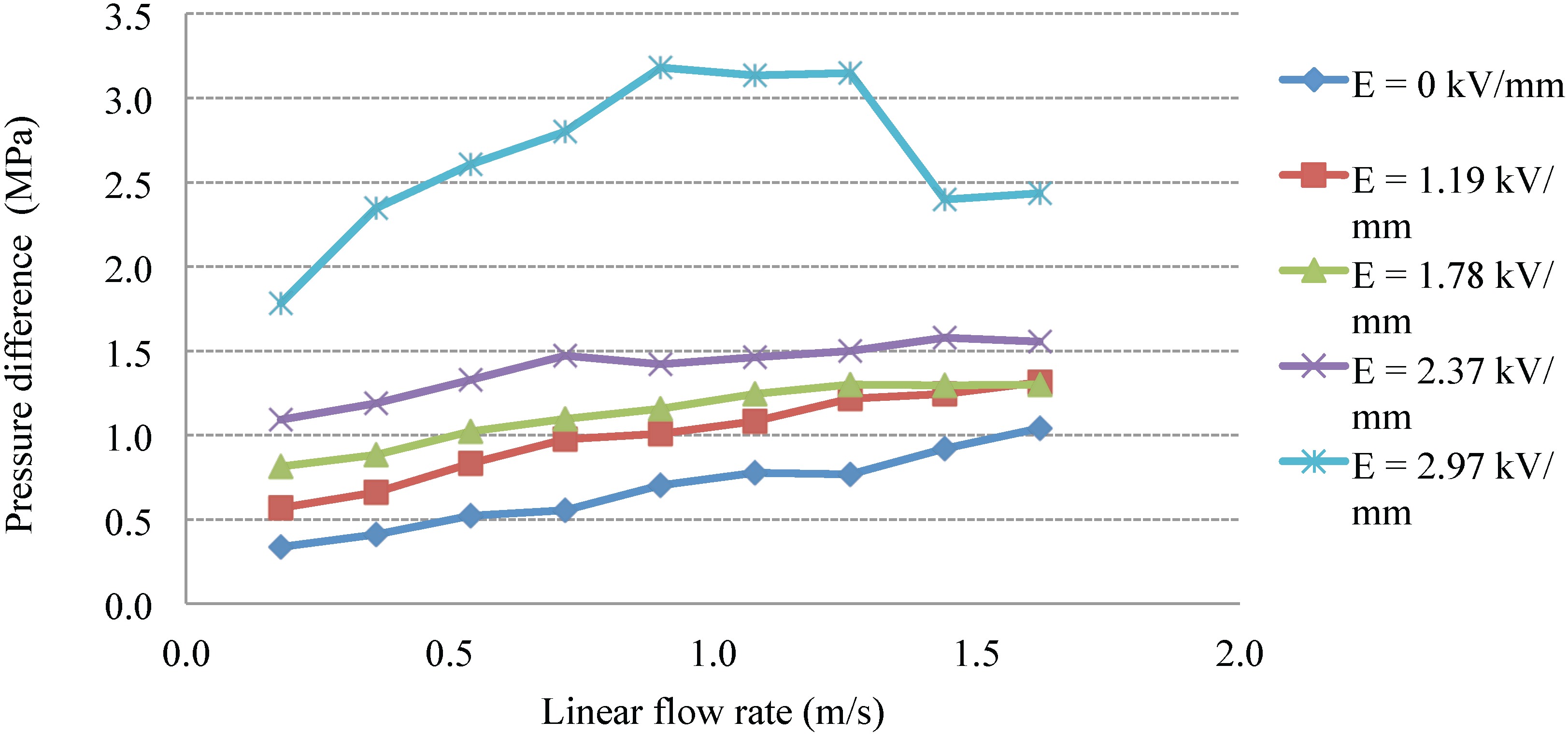
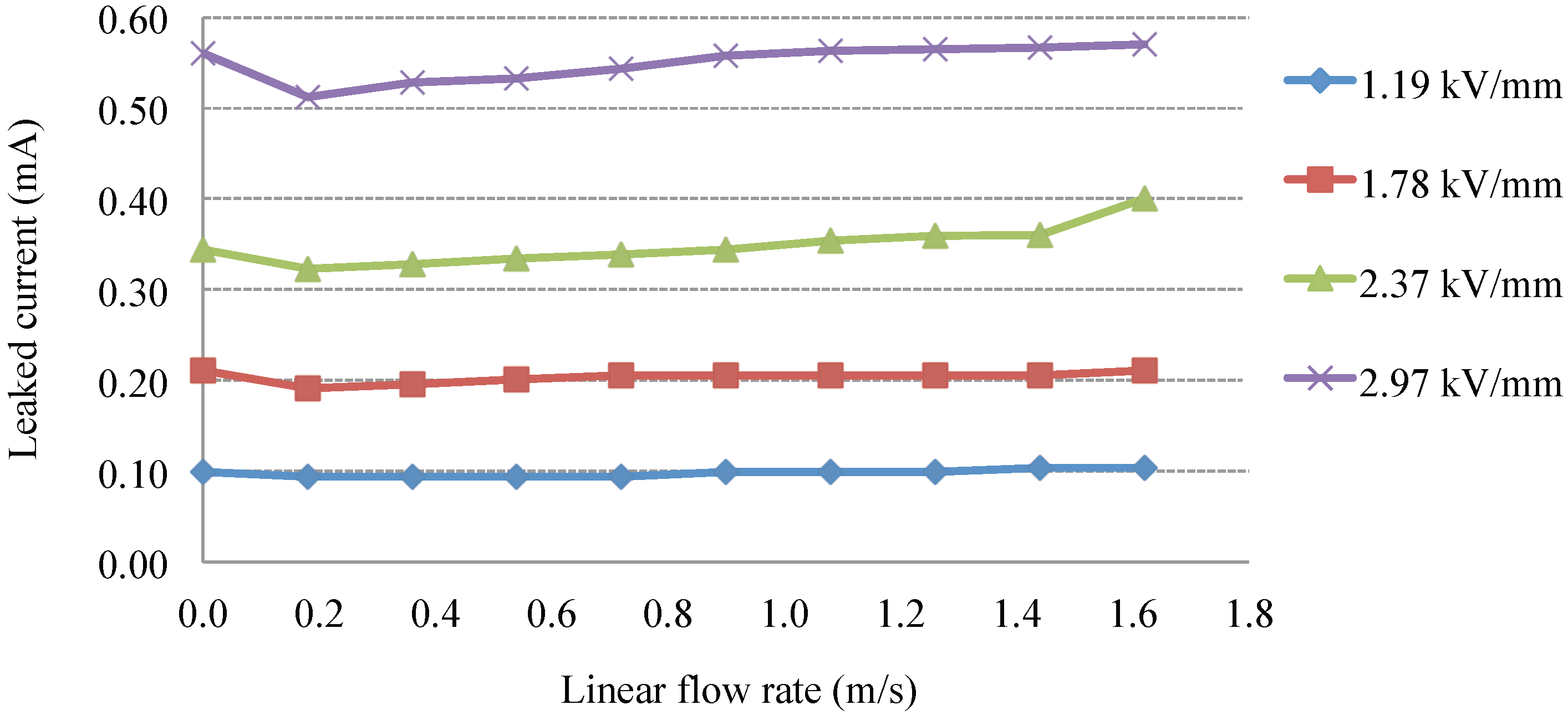
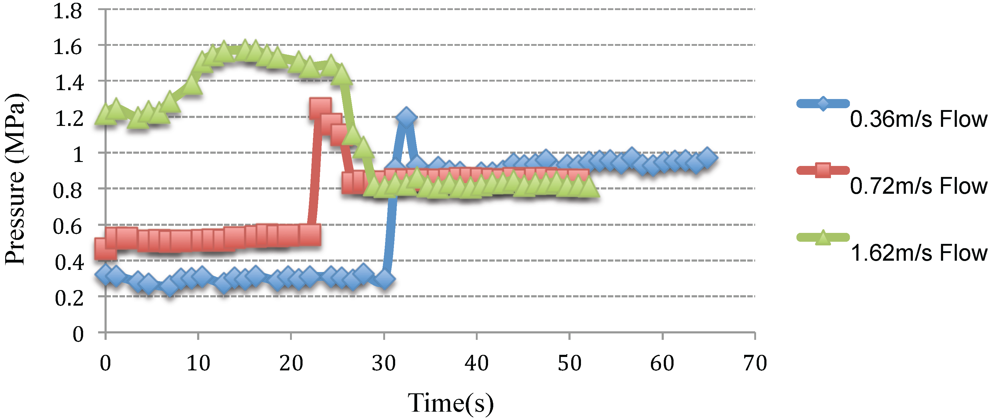
However, the results also show that changing flow rates can also affect the yield and arcing characteristics of the ERF valve. For high flow rates, the ERF valve takes longer to close, as it needs more time to form bonds. Additionally, the effective yield capability of the ERF valve decreases when the E-field is activated to close the valve at high flow rates. It is also possible that at much higher flow rates, the ERF valve may fail to close at all, since the ERF bonds potentially cannot form, and this is open for investigation in the future. For low flow rates, the ERF valve has a blocking pressure of 1 MPa, but for higher flow rates, this can decrease to 0.83 MPa. Lastly, higher flow rates cause the coating surface area of the ERF particles to increase, which makes the ERF more conductive, thereby increasing the possibility of arcing the ERF easier as the ERF shorts itself across the electrode plates.
When designing the ERF actuator, the results show that there is a clear trade-off between the selection of the operating flow rates. Higher flow rates decrease the ERF’s effective yield characteristics and increases the risk of arcing, since the ERF’s conductivity increases. On the other hand, operating in lower flow rates has a smaller risk of arcing, but it also decreases efficiency, as power demands increase due to the ERF’s high dynamic viscosity at low flow conditions.
In the future, it is important to identify how to optimize the trade-off between high and low flow rates to create the most efficient ERF actuator possible while also meeting design requirements. While other issues are still at large, as described in the section on design considerations, soon, an appropriate alternative to mechanical fluid valves will be available, and ERF-based hydraulic rotary actuators will be a reality. These ERF-based valves can potentially have longer operation times, occupy smaller volumes and operate at higher pressures.


