
A Novel Radially Closable Tubular Origami Structure (RC-ori) for Valves
by
 , , , and
Siyuan Ye
1 ,
,
Pengyuan Zhao
1,
Yinjun Zhao
1,
Fatemeh Kavousi
1,
Huijuan Feng
2 and
Guangbo Hao
1,* 1
School of Engineering and Architecture, University College Cork, T12 K8AF Cork, Ireland
2
Department of Mechanical and Construction Engineering, Faculty of Engineering and Environment, Northumbria University, Newcastle upon Tyne NE1 8ST, UK
*
Author to whom correspondence should be addressed.
Actuators 2022, 11(9), 243; https://doi.org/10.3390/act11090243
Submission received: 26 July 2022
/
Revised: 21 August 2022
/
Accepted: 22 August 2022
/
Published: 26 August 2022
(This article belongs to the Special Issue Mechanism Design and Control for Robotics)
Abstract
:Cylindrical Kresling origami structures are often used in engineering fields due to their axial stretchability, tunable stiffness, and bistability, while their radial closability is rarely mentioned to date. This feature enables a valvelike function, which inspired this study to develop a new origami-based valve. With the unique one-piece structure of origami, the valve requires fewer parts, which can improve its tightness and reduce the cleaning process. These advantages meet the requirements of sanitary valves used in industries such as the pharmaceutical industry. This paper summarizes the geometric definition of the Kresling pattern as developed in previous studies and reveals the similarity of its twisting motion to the widely utilized iris valves. Through this analogy, the Kresling structure’s closability and geometric conditions are characterized. To facilitate the operation of the valve, we optimize the existing structure and create a new crease pattern, RC-ori. This novel design enables an entirely closed state without twisting. In addition, a simplified modeling method is proposed in this paper for the non-rigid foldable cylindrical origami. The relationship between the open area and the unfolded length of the RC-ori structure is explored based on the modeling method with a comparison with nonlinear FEA simulations. Not only limited to valves, the new crease pattern could also be applied to microreactors, drug carriers, samplers, and foldable furniture.
1. Introduction
In recent years, continuous manufacturing (CM) technology in the pharmaceutical industry has been a hot topic [1]. Continuous feeding, as the front-end process of CM, has an important influence on the uniformity of material, which in turn determines the quality of the resulting product. Most continuous feeding equipment are loss-in-weight feeders (Figure 1), including ConsiGma [2], the powder-to-tablet CM solution developed by GEA Group, MODCOS [3], and Glatt GmbH’s concept. To maintain uninterrupted operations, a sufficient amount of material must be present in the hopper, which means the refilling process is essential. Additionally, this process is the main cause of deviation. When the refilling device is turned on, the rapid increase in material density causes the powder to flow uncontrollably through the screw, resulting in overfeeding. Engisch and Muzzio [4] analyzed various methods currently applied to address the problem and proposed that the deviation could be reduced by gently controlling the refill flow to replenish the feeder hopper.
There are several types of refill devices, including knife valves, modulating butterfly valves, and rotary valves [5]. The rotary valve can only roughly control the material flow, and it may tend to block when dealing with materials with poor fluidity [5]. Butterfly valves are not recommended for half-opening applications because their gaskets are prone to wear, and the valve disc is located in the middle of the flow path, which causes some damage to the product [6]. The same problems also exist in knife valves. In addition, on–off valves are not recommended to control flow [7]. Given the preceding, it is necessary to create a new flow control valve for pharmaceutical continuous feeders. It needs to comply with sanitary valve standards and avoid the above problems. A one-piece origami structure may provide an effective solution to these issues.
Origami technology, which originated in China and was popular in Japan, has been widely used in various fields. In addition to the typical applications used in aerospace (solar panels [8], inflatable booms [9], bellows for harsh environment [10], drilling-debris containment [11], and antennas [12]), medical support systems [13], robotic grippers [14], energy-absorbing devices [15,16], mechanical metamaterials [17], and even generators [18] also use origami for innovative research. Widely used origami crease patterns in engineering include Miura-ori, Yoshimura, waterbomb, Kresling, twist square, and Resch [19,20,21]. A variety of geometric forms can be created from these patterns, such as checkerboard, spiral, cylindrical, and spherical. Among them, cylindrical origami is highly suitable for valve design. Not only the structural shape is similar to the valve, but it can also support loads while offering tunable mechanical responses [22]. Typical cylindrical origami patterns include Yoshimura [23], Kresling [24], waterbomb [25], and Tachi–Miura [23] (Figure 2). Unlike the aerospace engineering field, which focuses on deployability, stowability, and portability [26], the valve is more concerned with the flat-foldability, radial closability, and the end shape’s consistency. The Kresling cylindrical structure can satisfy the above three points simultaneously.
The Kresling pattern was accidentally discovered in 1993 by a student of Biruta Kresling during a bionic class [27]. Almost simultaneously, Guest and Pellegrino also found a similar triangulated cylinder [28]. Over the past thirty years, the Kresling pattern has been used in many fields [8,9,10,11,12,13,14,15,16,17,18], and its monostable/bistable properties [29,30,31,32], non-rigid foldability [33,34,35,36], and flat-foldability [37,38] have attracted many researchers’ attentions. An analysis by Kidambi and Wang [30] showed that by changing the geometric parameters, the energy distribution of the Kresling pattern could be changed between monostable, asymmetric bistable, and symmetric bistable states. Masana and Daqaq [31] performed a detailed static analysis of the Kresling crease and constructed five springs with different properties. Cai et al. [29,34] demonstrated that the Kresling structure is non-rigid foldable and has a bistable behavior. Bhovad and Li [37] proposed a “generalized” Kresling pattern that can feature a non-zero length when fully folded. Apart from these, there are still many other characteristics to be explored, for example, radial closability, which is an essential feature when designing valves.
Twisting and folding the Kresling structure creates a diaphragm perpendicular to the tube axis [39]. Radial closability refers to the fact that, when the diaphragm intersects the tube axis, a complete barrier is created within the tube, which works similarly to the iris valve (Figure 3b). Iris valves, also known as diaphragm valves, are generally used for discharging the hoisted materials. They may be a good option for continuous feeding refill devices since they can ensure the integrity and uniformity of the material. However, their flexible sleeves make them impossible to support load and control flow accurately. Arora et al. [40] proposed a stiffness-based design approach for a compliant iris mechanism, but the sleeve is still a necessary component when used in valves. The Kresling structure may help to solve the problems. First, the inner diameter of the Kresling tube can be precisely adjusted by controlling the vertical length. Second, the Kresling panels can be rigid enough to withstand the load compared with the iris flexible sleeves, and the fully folded (unfolded) state of Kresling is a stable one without panel deformation. Additionally, the one-piece structure makes the valve easy to clean and assemble. To the best of our knowledge, the radial closability of the Kresling structure is rarely studied, and no one mentions its potential for valves when the diaphragm is fully closable.
Nevertheless, the inherent coupled twisting motion of the Kresling structure requires more parts and actuation design for the valve. Therefore, a new crease pattern is created in this paper, named RC-ori(radial closable origami). It enables a completely closed state without creating the undesired twisting, which reduces parts and simplifies assembly for easy cleaning and sealing. Moreover, this new structure is non-rigidly foldable like most cylindrical origami. Rigid foldability means that the small planes remain consistent during the continuous folding movement [23]. Cai et al. [34] conducted studies on the non-rigid foldability of cylindrical Kresling creases. Ma et al. [41] offered a mixed mode of mechanism–structure–mechanism transition in the folding process of the tubular waterbomb structure. Miura and Tachi [23] mentioned that the Yoshimura cylinder is not continuously foldable, and they created a rigid foldable cylindrical origami by combining Miura-ori and its mirror pattern. Non-rigid foldable structures often face challenges when modeling. Cai et al. [42] proposed to treat the crease as an axially deformed truss, which has been shown to be effective. Adding additional virtual folds to the triangular panels is also a good approach when studying the deformation of the panels [43]. In this paper, we propose a different method for the kinematic analysis of the new structure, which makes the structure a kirigami by eliminating the over-constraint of the connections between the elements.
The main contributions of this paper are summarized here:
- i
- The radial closability of the Kresling structure is first studied targeting for valve applications.
- ii
- A new crease pattern is created without twisting motion for the valve application.
- iii
- A simplified kinematic modeling method is proposed for the non-rigid foldable cylindrical origami.
This paper is organized as follows. Section 2 describes the geometric definition of the general Kresling pattern and its radial closability. Section 3 introduces a new crease pattern, RC-ori. By analyzing its non-rigid foldability, a simplified kirigami modeling method is proposed for the kinematic analysis. Section 4 is the conclusion. This new design can be used not only for valves but also for microreactors, drug carriers, samplers, and foldable furniture.
2. Radial Closability of the Kresling Pattern
2.1. Geometric Definition of the Kresling Pattern
The geometric definition of the Kresling pattern is established before exploring its radial closability. This paper only discusses the single-stacked Kresling structure and assumes that the tube ends remain parallel during the folding process. It is generally accepted that the Kresling structure is a cylinder composed of multiple parallelograms, each of which is separated diagonally by a valley crease (Figure 4). Biruta [24,39] narrowed this definition according to the shape generated by natural twist buckling:
- (1)
- The parallelograms are inclined and elongated;
- (2)
- The valley-folds are long diagonals;
- (3)
- The structure will create a two-dimensional diaphragm perpendicular to the axis of the cylinder when fully collapsed;
- (4)
- The axial length of the fully deployed diaphragm is less than the diameter of the cylinder (Figure 4b).
Under these conditions, Biruta [27] concluded that three parameters could fully define the natural Kresling pattern: modes, chirality, and the number of polygonal sides. However, most researchers use different parameters from a purely geometric perspective. For example, some researchers use the number of polygonal sides, the side length of the polygon (or the cylinder radius), and a planar angular fraction [32,33]. Similarly, Kidambi and Wang [30] considered the third parameter as a stress-free orientation angle, and Hunt and Ario [44] considered it as the axial length. Sargent et al. [13] and Herron [45] defined the Kresling structure by the outer diameter, folded-state inner diameter, and the number of polygonal sides.
Nevertheless, manual replication can create cylinders with different Kresling patterns [24]. In general, at least four parameters are needed to define the pattern in this case [31,35,46]. For example, when the valley-folds are short diagonals, four parameters are required to determine the crease uniquely. This structure can be applied to metamaterials [17] and non-volatile mechanical memory storage devices [47]. Meanwhile, four parameters are also required when the diaphragm thickness is non-zero in the fully folded state. Bhovad et al. [37] and Berre et al. [48] investigated the properties of this particular structure, which provided new ideas for Kresling’s design. A special case arises when using parallelograms such as rhombus [49] or rectangles [12]. Only three parameters are required since the basic elements only need two parameters to define. The rectangular Kresling pattern will be used in the next section on the Kresling structure’s radial closability.
The suitable parameters and their value range are defined here based on the above studies. Since a flat 2D diaphragm is easy to operate and control for the valve, conditions (2) and (3) are necessary. The diagonal length is a crucial parameter, as the diagonal is folded towards the tube axis and forms the inner polygon during the folding process [27]. When the diagonal length is larger than the cylinder diameter, the 2D diaphragm cannot be formed. Conversely, when the diagonal length is less than or equal to the diameter of the cylinder, it is possible to generate the 2D diaphragm. Still, it depends on the covered angle because the panels will partially overlap when generating the diaphragm (Figure 4), then, we have the following expression:
Thus,
In this condition, three parameters can completely define the Kresling pattern: the number of polygonal sides n, the side length of the polygon c, and the diagonal length l. The following are their value ranges:
- (a)
- ;
- (b)
- ;
- (c)
2.2. Radial Closability of the Kresling Pattern
Radial closability refers to the intersection of the diagonal of each element with the tube axis when fully folded, which creates a barrier that completely closes the tube. It is different from the closure condition stated by Zhang et al. [50], which refers to the horizontal creases that constitute regular polygons from the initial planar configuration to the folded configuration. The radial closure conditions can be derived from the fully folded state since the diagonal’s midpoint falls at the polygon’s center (Figure 5). Then,
Only two parameters (n, c) are enough to fully define a radially closable Kresling structure. Substituting Equation (2) into Equation (3), we can see that the geometric element is a rectangle rather than an inclined and elongated parallelogram (Figure 6). This can also be verified with Thales’ theorem [51].
When this structure is applied to a valve, the unfolded length H between the two polygons can be used as a controllable variable (Figure 5a),
where b is the side length of the right angle (Figure 6).
Since the Kresling structure is non-rigid foldable, we assume that the diagonal length l is constant when deriving the relationship between the inner radius and the unfolded length H, and the deformation only happens inside the panel. As shown in Figure 7, when point moves along the big arc, the midpoint of the diagonal projection moves along the small arc.
The inner radius equals the distance between the polygon center B and midpoint projection . Thus, can be expressed as:
is the diameter of the circumcircle, and is the projected length of the diagonal. Combining Equations (6)–(8), is written as:
As an important parameter in valve flow control, the area of the hollow polygonal region (inner yellow hexagon) can be obtained as:
The radial closability of the Kresling structure is well worth studying. In addition to the application potential of valves, other fields such as drug carriers, locking mechanisms, and folding furniture can also benefit from this feature. Multiple radially closable structures in series or parallel can even be used in microreactors or samplers. The same properties and applications are also applicable in the new crease pattern mentioned below.
3. New Radially Closable Structure(RC-ori)
Although the twisting motion of the Kresling structure has been used for many innovative designs such as generators [18], mechanical metamaterials [17], and crawling robots [33], it makes valves more difficult to manufacture and control. Avoiding the twisting motion could simplify the valve design. Although the already developed double-stacked symmetrical Kresling structure also requires no twisting, it increases the axial length. This paper, therefore, proposes a new closable mechanism that requires neither twisting motion nor additional axial length. This novel structure is named RC-ori.
The goal-directed creation process of the RC-ori is explained in detail as follows. The diaphragm consists of multiple identical isosceles triangles in the fully closed state (Figure 5e). When these isosceles triangles are drawn on flat paper, the pattern shown in Figure 8a can be obtained. The white area is folded into four overlapping right triangles along the centerline and sandwiched between the upper and lower isosceles triangles when the cylinder is fully folded. They help the isosceles triangles form the complete one-piece structure of the origami. So far, the single element of the new crease is similar to the waterbomb pattern, and the arrangement makes it look more like a Yoshimura pattern.
To avoid unnecessary overlap, the white areas are folded in the same direction, which means two creases are redundant in each element, as shown in Figure 8b. According to Kawasaki’s and Maekawa’s Theorems, every vertex of the RC-ori crease pattern is flat-foldable. Now, it looks like a combination of two truncated Kresling patterns with opposite chirality, which can also be used to explain why the twist motion is canceled. Meanwhile, the new crease pattern is also analogous to an irregular sequence of Miura-ori pattern. Two parameters can fully define the RC-ori crease pattern, the number of polygon sides n and the polygon side length 2a, other parameters can be derived by the following:
where is the base angle of the isosceles triangle and is also half of the polygon interior angle, is the initial axial length of the diaphragm, and is the polygon circumcircle diameter.
3.1. Non-Rigid Foldability of RC-ori
When considering a single element of RC-ori, it is a typical four-degree vertex crease pattern with one degree of freedom (Figure 8b). It is well-known that the four-degree vertex can be represented by a spherical four-bar linkage and is often used as the base model for thick origami research due to their commonality and simplicity [52,53,54,55,56,57]. By applying rigid material to the panel and revolute joints to the creases, we find that the RC-ori structure is not rigid foldable when all vertices are fixed to one another. However, it is easy to rigidly fold from a flat state to a polygonal prism. A similar feature can also be found in the Kresling structure [58]. This is because when fully defining the position of each vertex relative to its neighbors, additional constraints are created, which makes the design no longer have an available degree of freedom [33]. In short, each element has its own motion trajectory, and the motion trajectories of the connected edges do not always coincide during the folding process, as shown in Figure 9a. https://youtube.com/shorts/E0uF6XN1cNQ (accessed on 25 August 2022) (see video in Appendix A).This can be proved by establishing a coordinate system and analyzing the motion trajectories of the midpoints and separately. This makes the structure a kirigami model, where we cut the crease while keeping the endpoints /) connected. Figure 9b takes n = 6 as an example to establish the D-H coordinate system and obtains the position of each point during the folding motion, as shown in Table 1.
h is the unfolded length of the diaphragm during the folding process, which is the only independent variable, and is the y coordinate value of point .
moves around a sphere centered at and a sphere centered at . is the midpoint of the connection side which moves around a sphere centered at . The points , , and are at the same height. Therefore, the motion trajectory of point can be obtained by combining the Equations (15)–(17).
The position of in the coordinate system can be obtained by the transformation matrix (18) and Equation (19):
Since the z-axis coordinates of and are consistent, their trajectories can be expressed by the trajectories on the x–y plane. As shown in Figure 10c, we find that the position of and coincide in the fully folded and fully unfolded state, while their trajectories do not overlap during the folding process, which indicates that deformation occurs. Meanwhile, we suspect this is a bistable structure, but verification will need to be carried out through further analysis.
Researchers have used different methods to verify the rigid foldability of cylindrical origami [23,34,41,58,59]. This paper proposes another approach for the new structure RC-ori: under the condition that the cylindrical origami is composed of uniform elements and each element is working the same way, when a single element of the cylindrical origami structure has one degree of freedom, if the motion trajectories of the connection’s vertices do not always coincide during folding, then the design is non-rigid foldable. Although this method works well in the new structure, it may not suit all cylindrical origami.
3.2. Kinematic Analysis of RC-ori
The RC-ori structure presents different opening areas S at different unfolded lengths h, which meets the basic design requirements of flow control valves. Therefore, it is necessary to obtain the relationship between S and h to control the flow rate accurately. Since the overconstraints occurred at the connection of each element, we apply the kirigami model for the kinematic analysis, in which only the endpoints and of each element connection remain. To verify the feasibility of this arrangement, the motion trajectory of point P in the finite element analysis results and the rigidly foldable kirigami counterpart results (Equation (20)) are analyzed and compared, as shown in Figure 11. Additionally, for a better understanding, we also make some prototypes, as shown in Figure 12.
We set flexible material at the crease to make the structure fold along with the crease pattern in the simulation with ABAQUS. The model is a prism shell with a side length of 100 mm and a thickness of 1 mm. The crease width is 4 mm and its Young’s modulus is 0.1 MPa, while the Young’s modulus of the panels is 1 MPa (paper). We fix one end and apply a displacement of 160mm on the other end. Moreover, to make the crease fold in the desired direction, we apply a disturbance moment load of 0.005 Nmm (Figure 11a).
In Figure 11b, the x-axis is the height of the point , and the y-axis is the distance from the point to the polygon axis . It can be seen that there is only a small difference in the motion trajectories of the point , indicating that this arrangement is applicable for the kinematic analysis.
Therefore, the kinematic analysis is simplified by considering each element separately. As can be seen from Figure 13a, in the half-folded state, the open area is equal to the polygon area minus the covered area, which is
Figure 13b shows the relationship between h and S. It can be seen that there is only one circumstance for the open area when n = 3 and n = 4, while there are three cases when , as shown in Figure 14. When it starts to fold, there are three covered triangles of each element in the top view. When it is folded to a certain extent, one of the covered triangles is overlapped. Nonetheless, the difference in the curve trend between the three cases is small. Meanwhile, when the structure is fully folded (h = 0), the tube is completely closed (S = 0), and when it is fully unfolded (h = ), the opening area is equal to the polygonal area (S = ), which meets the valve control requirement well. Figure 13b also shows that the adjustment range of the opening area expands with the increase in n, and the expansion is insignificant when , which means the hexagonal prism(n = 6) is an ideal option for modeling.
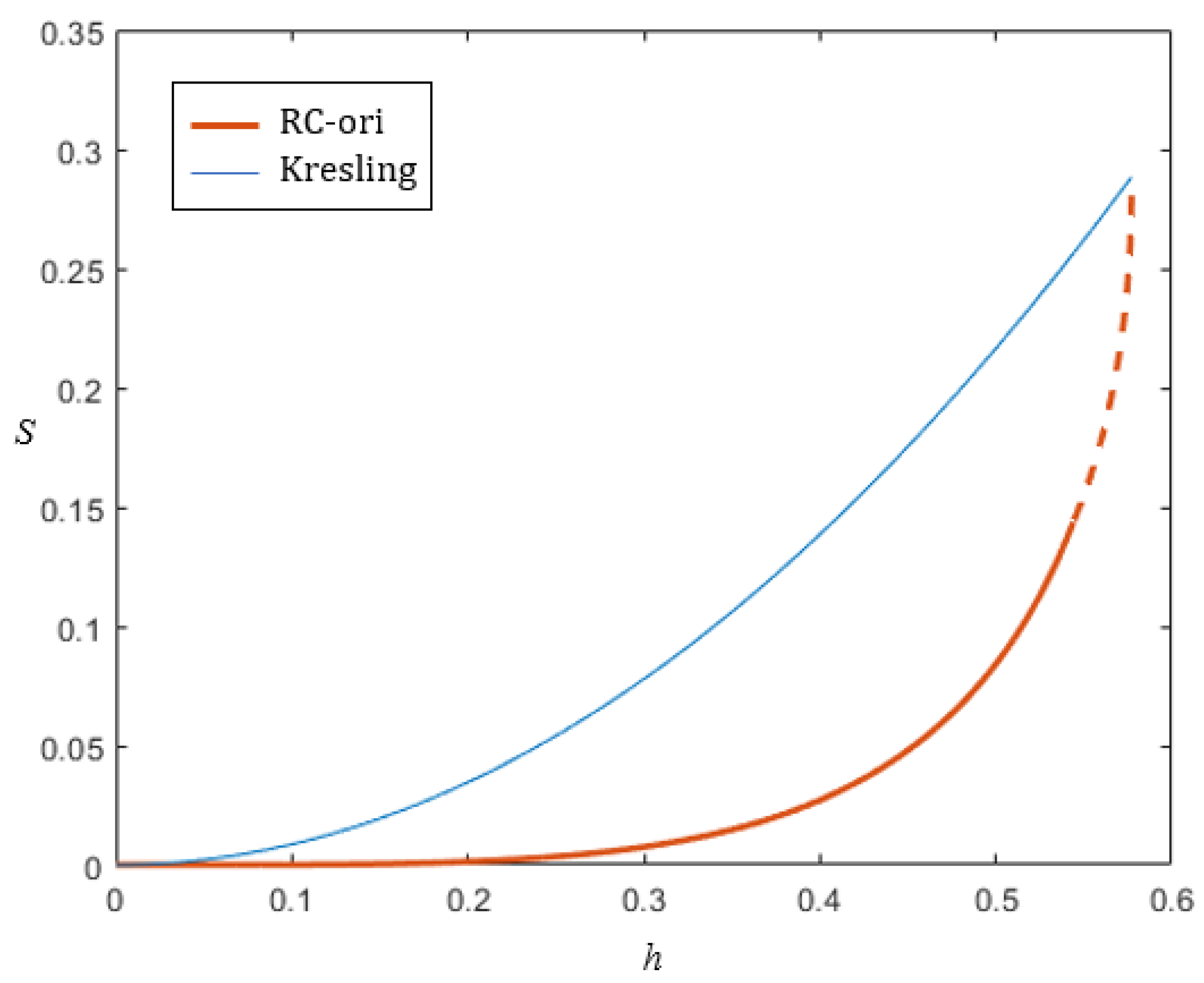
More importantly, when comparing with the Kresling structure, as shown in Figure 15, the RC-ori design is ideal for micro-feed control because there is little change in the opening area when the tube is folded to a certain extent.
4. Conclusions
Oriented by the application of the valve, this paper analyzes the geometry and the radial closability of the Kresling structure and proposes its potential for valve application. Additionally, a new crease pattern (RC-ori) is created to avoid a twisting motion, which can simplify valve operation without adding extra length to the tube. The new tubular structure is a combination of two symmetrical truncated Kresling patterns and a new method is proposed to check its non-rigid foldability. Inspired by the kirigami technique, the overconstrained connections are removed, which provides a new modeling method for non-rigid cylindrical origami in its kinematic analysis. Meanwhile, the relationship between the unfolded length and the open area of the RC-ori structure is obtained. The result shows little change in the opening area when the tube is nearly fully folded, making the new design a good choice for micro-flow control valves.
5. Future Works
This is very much the key component in future attempts to overcome the gap of the kirigami structure of the RC-ori and its non-rigid foldability. We will try to add virtual creases [20,33] or use flexible membrane [60,61] or compliant joints [62,63,64] to solve the above and convert the overall deformation to the local compliant joints deformation. A prototype for the valve application will be produced to verify its function and to optimize the structure design.
Author Contributions
Conceptualization, G.H. and S.Y.; methodology, G.H., S.Y. and Y.Z.; software, S.Y. and P.Z.; validation, G.H. and S.Y.; formal analysis, G.H. and S.Y.; investigation, S.Y.; data curation, S.Y.; writing—original draft preparation, S.Y.; writing—review and editing, S.Y., P.Z., Y.Z., F.K., H.F. and G.H.; visualization, S.Y.; supervision, G.H., H.F. and F.K.; project administration, G.H.; funding acquisition, S.Y., P.Z. and Y.Z. All authors have read and agreed to the published version of the manuscript.
Funding
This research received no external funding.
Institutional Review Board Statement
Not applicable.
Informed Consent Statement
Not applicable.
Data Availability Statement
Not applicable.
Acknowledgments
The authors (Siyuan Ye, Pengyuan Zhao and Yinjun Zhao) are grateful for the financial support from the China Scholarship Council (CSC).
Conflicts of Interest
The authors declare no conflict of interest.
Appendix A
https://youtube.com/shorts/E0uF6XN1cNQ (accessed on 25 August 2022).
References
- Teżyk, M.; Milanowski, B.; Ernst, A.; Lulek, J. Recent progress in continuous and semi-continuous processing of solid oral dosage forms: A review. Drug Dev. Ind. Pharm. 2016, 42, 1195–1214. [Google Scholar] [CrossRef] [PubMed]
- GEA Group. Continuous Processing—Solutions for Oral Solid Dosage Forms. 2020. Available online: https://www.gea.com/en/binaries/Pharmaceutical-Continuous-Processing-for-oral-solid-dosage-forms_tcm11-31710.pdf (accessed on 25 August 2022).
- Glatt GmbH. Modcos—Full Control in Continuous Operation. 2016. Available online: https://www.glatt.com/wp-content/uploads/2021/03/GLATT_BRO_PTPH_168_MODCOS_2016_03_EN.pdf (accessed on 25 August 2022).
- Engisch, W.E.; Muzzio, F.J. Feedrate deviations caused by hopper refill of loss-in-weight feeders. Powder Technol. 2015, 283, 389–400. [Google Scholar] [CrossRef]
- K-Tron International, Inc. Smart Refill Technologyin Loss-in-Weight Feeding. 2009. Available online: https://www.mmsonline.com/cdn/cms/uploadedFiles/Ktron-Smart_Refill.pdf (accessed on 25 August 2022).
- Powderprocess.net. Butterfly Valve for Bulk and Powder Process. Available online: https://www.powderprocess.net/Equipments%20html/Butterfly_valve.html (accessed on 25 August 2022).
- McMillan, G.; Vegas, H. 101 Tips for a Successful Automation Career; ISA: Research Triangle Park, NC, USA, 2013. [Google Scholar]
- Zirbel, S.A.; Lang, R.J.; Thomson, M.W.; Sigel, D.A.; Walkemeyer, P.E.; Trease, B.P.; Magleby, S.P.; Howell, L.L. Accommodating Thickness in Origami-Based Deployable Arrays1. J. Mech. Des. 2013, 135, 111005. [Google Scholar] [CrossRef]
- Schenk, M.; Viquerat, A.D.; Seffen, K.A.; Guest, S.D. Review of Inflatable Booms for Deployable Space Structures: Packing and Rigidization. J. Spacecr. Rocket. 2014, 51, 762–778. [Google Scholar] [CrossRef]
- Butler, J.; Morgan, J.; Pehrson, N.; Tolman, K.; Bateman, T.; Magleby, S.P.; Howell, L.L. Highly Compressible Origami Bellows for Harsh Environments. In Proceedings of the 40th Mechanisms and Robotics Conference, International Design Engineering Technical Conferences and Computers and Information in Engineering Conference, Charlotte, NC, USA, 21–24 August 2016;B; Volume 50169, p. V05BT07A001. [Google Scholar] [CrossRef]
- Butler, J.; Magleby, S.; Howell, L.; Mancini, S.; Parness, A. Highly Compressible Origami Bellows for Microgravity Drilling-Debris Containment. In Proceedings of the AIAA SPACE and Astronautics Forum and Exposition, Orlando, FL, USA, 12–14 September 2017; p. 5341. [Google Scholar] [CrossRef]
- Yao, S.; Bao, K.; Liu, X.; Georgakopoulos, S.V. Tunable UHF origami spring antenna with actuation system. In Proceedings of the 2017 IEEE International Symposium on Antennas and Propagation & USNC/URSI National Radio Science Meeting, San Francisco, CA, USA, 9–14 July 2017; pp. 325–326. [Google Scholar]
- Sargent, B.; Butler, J.; Seymour, K.; Bailey, D.; Jensen, B.; Magleby, S.; Howell, L. An Origami-Based Medical Support System to Mitigate Flexible Shaft Buckling. J. Mech. Robot. 2020, 12, 041005. [Google Scholar] [CrossRef]
- Lee, K.; Wang, Y.; Zheng, C. Twister hand: Underactuated robotic gripper inspired by origami twisted tower. IEEE Trans. Robot. 2020, 36, 488–500. [Google Scholar] [CrossRef]
- Qi, J.; Li, C.; Tie, Y.; Zheng, Y.; Duan, Y. Energy absorption characteristics of origami-inspired honeycomb sandwich structures under low-velocity impact loading. Mater. Des. 2021, 207, 109837. [Google Scholar] [CrossRef]
- Li, J.; Chen, Y.; Feng, X.; Feng, J.; Sareh, P. Computational modeling and energy absorption behavior of thin-walled tubes with the Kresling origami pattern. J. Int. Assoc. Shell Spat. Struct. 2021, 62, 71–81. [Google Scholar] [CrossRef]
- Zhai, Z.; Wang, Y.; Jiang, H. Origami-inspired, on-demand deployable and collapsible mechanical metamaterials with tunable stiffness. Proc. Natl. Acad. Sci. USA 2018, 115, 2032–2037. [Google Scholar] [CrossRef]
- Chung, J.; Song, M.; Chung, S.H.; Choi, W.; Lee, S.; Lin, Z.H.; Hong, J.; Lee, S. Triangulated Cylinder Origami-Based Piezoelectric/Triboelectric Hybrid Generator to Harvest Coupled Axial and Rotational Motion. Research 2021, 2021, 7248579. [Google Scholar] [CrossRef]
- Turner, N.; Goodwine, B.; Sen, M. A review of origami applications in mechanical engineering. Proc. Inst. Mech. Eng. Part C J. Mech. Eng. Sci. 2016, 230, 2345–2362. [Google Scholar] [CrossRef]
- Ma, J.; Zang, S.; Feng, H.; Chen, Y.; You, Z. Theoretical characterization of a non-rigid-foldable square-twist origami for property programmability. Int. J. Mech. Sci. 2021, 189, 105981. [Google Scholar] [CrossRef]
- Callens, S.J.; Zadpoor, A.A. From flat sheets to curved geometries: Origami and kirigami approaches. Mater. Today 2018, 21, 241–264. [Google Scholar] [CrossRef]
- Filipov, E.T.; Tachi, T.; Paulino, G.H. Origami tubes assembled into stiff, yet reconfigurable structures and metamaterials. Proc. Natl. Acad. Sci. USA 2015, 112, 12321–12326. [Google Scholar] [CrossRef] [PubMed]
- Miura, K.; Tachi, T. Synthesis of rigid-foldable cylindrical polyhedra. Symmetry Art Sci. 2010, 2010, 204–213. [Google Scholar]
- Kresling, B. Natural twist buckling in shells: From the hawkmoth’s bellows to the deployable Kresling-pattern and cylindrical Miura-ori. In Proceedings of the IASS-IACM 2008 Spanning Nano to Mega, Ithaca, NY, USA, 28–31 May 2008. [Google Scholar]
- Chen, Y.; Feng, H.; Ma, J.; Peng, R.; You, Z. Symmetric waterbomb origami. Proc. R. Soc. Math. Phys. Eng. Sci. 2016, 472, 20150846. [Google Scholar] [CrossRef]
- Morgan, J.; Magleby, S.P.; Howell, L.L. An approach to designing origami-adapted aerospace mechanisms. J. Mech. Des. 2016, 138, 052301. [Google Scholar] [CrossRef]
- Kresling, B. The fifth fold: Complex symmetries in Kresling-origami patterns. Symmetry Cult. Sci. 2020, 31, 403–416. [Google Scholar] [CrossRef]
- Guest, S.D.; Pellegrino, S. The Folding of Triangulated Cylinders, Part II: The Folding Process. J. Appl. Mech. 1994, 61, 778–783. [Google Scholar] [CrossRef]
- Jianguo, C.; Xiaowei, D.; Ya, Z.; Jian, F.; Yongming, T. Bistable Behavior of the Cylindrical Origami Structure With Kresling Pattern. J. Mech. Des. 2015, 137, 061406. [Google Scholar] [CrossRef]
- Kidambi, N.; Wang, K.W. Dynamics of Kresling origami deployment. Phys. Rev. E 2020, 101, 063003. [Google Scholar] [CrossRef] [PubMed]
- Masana, R.; Daqaq, M.F. Equilibria and bifurcations of a foldable paper-based spring inspired by Kresling-pattern origami. Phys. Rev. E 2019, 100, 063001. [Google Scholar] [CrossRef] [PubMed]
- Nayakanti, N.; Tawfick, S.H.; Hart, A.J. Twist-coupled Kirigami cells and mechanisms. Extrem. Mech. Lett. 2018, 21, 17–24. [Google Scholar] [CrossRef]
- Pagano, A.; Yan, T.; Chien, B.; Wissa, A.; Tawfick, S. A crawling robot driven by multi-stable origami. Smart Mater. Struct. 2017, 26, 094007. [Google Scholar] [CrossRef]
- Jianguo, C.; Yangqing, L.; Ruijun, M.; Jian, F.; Ya, Z. Nonrigidly Foldability Analysis of Kresling Cylindrical Origami. J. Mech. Robot. 2017, 9, 041018. [Google Scholar] [CrossRef]
- Li, Z.; Kidambi, N.; Wang, L.; Wang, K.W. Uncovering rotational multifunctionalities of coupled Kresling modular structures. Extrem. Mech. Lett. 2020, 39, 100795. [Google Scholar] [CrossRef]
- Chen, Y.; Fan, L.; Bai, Y.; Feng, J.; Sareh, P. Assigning mountain-valley fold lines of flat-foldable origami patterns based on graph theory and mixed-integer linear programming. Comput. Struct. 2020, 239, 106328. [Google Scholar] [CrossRef]
- Bhovad, P.; Li, S. Using Multi-Stable Origami Mechanism for Peristaltic Gait Generation: A Case Study. In Proceedings of the 42nd Mechanisms and Robotics Conference, Quebec City, QC, Canada, 26–29 August 2018; p. V05BT07A061. [Google Scholar] [CrossRef]
- He, Z.; Guest, S.D. On rigid origami I: Piecewise-planar paper with straight-line creases. Proc. R. Soc. A 2019, 475, 20190215. [Google Scholar] [CrossRef] [Green Version]
- Kresling, B. Folded Tubes as Compared to Kikko (“Tortoise-Shell”) Bamboo. In Origami3; Thomas, H., Ed.; Google Books: Mountain View, CA, USA, 2002; pp. 197–207. [Google Scholar]
- Arora, V.; Kumar, P.; Kumar, R.; Khatait, J.P. Design of Compliant Iris. In Machines, Mechanism and Robotics; Springer: New York, NY, USA, 2022; pp. 911–917. [Google Scholar]
- Ma, J.; Feng, H.; Chen, Y.; Hou, D.; You, Z. Folding of tubular waterbomb. Research 2020, 2020, 1735081. [Google Scholar] [CrossRef]
- Jianguo, C.; Xiaowei, D.; Yuting, Z.; Jian, F.; Ya, Z. Folding Behavior of a Foldable Prismatic Mast With Kresling Origami Pattern. J. Mech. Robot. 2016, 8, 031004. [Google Scholar] [CrossRef]
- Liu, K.; Paulino, G. Nonlinear mechanics of non-rigid origami: An efficient computational approach. Proc. R. Soc. Math. Phys. Eng. Sci. 2017, 473, 20170348. [Google Scholar] [CrossRef] [PubMed]
- Hunt, G.W.; Ario, I. Twist buckling and the foldable cylinder: An exercise in origami. Int. J. Non-Linear Mech. 2005, 40, 833–843. [Google Scholar] [CrossRef]
- Herron, J.D. Augmented Design Capabilities for Origami Tessellations. In All Thesis and Dissertations; Brigham Young University: Provo, UT, USA, 2018; pp. 18–30, 6855. [Google Scholar]
- Liu, X.; Yao, S.; Cook, B.S.; Tentzeris, M.M.; Georgakopoulos, S.V. An Origami Reconfigurable Axial-Mode Bifilar Helical Antenna. IEEE Trans. Antennas Propag. 2015, 63, 5897–5903. [Google Scholar] [CrossRef]
- Yasuda, H.; Tachi, T.; Lee, M.; Yang, J. Origami-based tunable truss structures for non-volatile mechanical memory operation. Nat. Commun. 2017, 8, 962. [Google Scholar] [CrossRef]
- Berre, J.; Geiskopf, F.; Rubbert, L.; Renaud, P. Towards the design of kresling tower origami as a compliant building block. J. Mech. Robot. 2022, 14, 045002. [Google Scholar] [CrossRef]
- Liu, X.; Yao, S.; Georgakopoulos, S.V.; Cook, B.S.; Tentzeris, M.M. Reconfigurable helical antenna based on an origami structure for wireless communication system. In Proceedings of the 2014 IEEE MTT-S International Microwave Symposium (IMS2014), Tampa, FL, USA, 1–6 June 2014; pp. 1–4. [Google Scholar] [CrossRef]
- Zhang, Q.; Cai, J.; Li, M.; Feng, J. Bistable behaviour of a deployable cylinder with Kresling pattern. In Proceedings of the 7th International Meeting on Origami in Science, Mathematics and Education (7OSME), Oxford, UK, 4–7 September 2018; pp. 4–7. [Google Scholar]
- Heath, T.L. A History of Greek Mathematics: From Thales to Euclid; The Clarendon Press: Oxford, UK, 1921; Volume I, p. 131. [Google Scholar]
- Lang, R.J.; Tolman, K.A.; Crampton, E.B.; Magleby, S.P.; Howell, L.L. A Review of Thickness-Accommodation Techniques in Origami-Inspired Engineering. Appl. Mech. Rev. 2018, 70, 010805. [Google Scholar] [CrossRef]
- Chen, Y.; Peng, R.; You, Z. Origami of thick panels. Science 2015, 349, 396–400. [Google Scholar] [CrossRef] [Green Version]
- Bowen, L.; Baxter, W.; Magleby, S.; Howell, L. A position analysis of coupled spherical mechanisms found in action origami. Mech. Mach. Theory 2014, 77, 13–24. [Google Scholar] [CrossRef]
- Dai, J.S.; Rees Jones, J. Mobility in Metamorphic Mechanisms of Foldable/Erectable Kinds. J. Mech. Des. 1999, 121, 375–382. [Google Scholar] [CrossRef]
- Qiu, C.; Zhang, K.; Dai, J.S. Repelling-Screw Based Force Analysis of Origami Mechanisms. J. Mech. Robot. 2016, 8, 031001. [Google Scholar] [CrossRef]
- Chen, Y.; Yan, J.; Feng, J.; Sareh, P. Particle swarm optimization-based metaheuristic design generation of non-trivial flat-foldable origami tessellations with degree-4 vertices. J. Mech. Des. 2021, 143, 011703. [Google Scholar] [CrossRef]
- Bös, F.; Wardetzky, M.; Vouga, E.; Gottesman, O. On the Incompressibility of Cylindrical Origami Patterns. J. Mech. Des. 2016, 139, 021404. [Google Scholar] [CrossRef]
- Cai, J.; Zhang, Y.; Xu, Y.; Zhou, Y.; Feng, J. The Foldability of Cylindrical Foldable Structures Based on Rigid Origami. J. Mech. Des. 2016, 138, 031401. [Google Scholar] [CrossRef]
- Chen, G.; Magleby, S.P.; Howell, L.L. Membrane-Enhanced Lamina Emergent Torsional Joints for Surrogate Folds. J. Mech. Des. 2018, 140, 062303. [Google Scholar] [CrossRef]
- Melancon, D.; Forte, A.E.; Kamp, L.M.; Gorissen, B.; Bertoldi, K. Inflatable Origami: Multimodal Deformation via Multistability. Adv. Funct. Mater. 2022, 2201891. [Google Scholar] [CrossRef]
- Hao, G.; Yu, J.; Li, H. A Brief Review on Nonlinear Modelling Methods and Applications of Compliant Mechanisms. Front. Mech. Eng. 2016, 11, 119–128. [Google Scholar] [CrossRef]
- Hao, G.; Kong, X. A Novel Large-Range XY Compliant Parallel Manipulator With Enhanced Out-of-Plane Stiffness. J. Mech. Des. 2012, 134, 061009. [Google Scholar] [CrossRef]
- Jacobsen, J.O.; Chen, G.; Howell, L.L.; Magleby, S.P. Lamina Emergent Torsional (LET) Joint. Mech. Mach. Theory 2009, 44, 2098–2109. [Google Scholar] [CrossRef]
Figure 1.
Loss-in-weight continuous feeder. Adapted with permission from Ref. [4]. Copyright 2015 Elsevier.
Figure 1.
Loss-in-weight continuous feeder. Adapted with permission from Ref. [4]. Copyright 2015 Elsevier.

Figure 2.
Cylindrical origami. (a) Yoshimura pattern. Reprinted with permission from [23]. Copyright 2010 Royal Society. (b) Kresling pattern. Reprinted with permission from [24]. Copyright 2008 Royal Society. (c) Waterbomb pattern. Reprinted with permission from [25]. Copyright 2016 Royal Society. (d) Tachi–Miura pattern. Reprinted with permission from [23]. Copyright 2010 Royal Society.

Figure 3.
Iris valves. (a) Different sizes of iris valve. (b) The folding process of iris valve sleeves. (Images from https://www.mucon.com/ (access on 25 August 2022)).
Figure 3.
Iris valves. (a) Different sizes of iris valve. (b) The folding process of iris valve sleeves. (Images from https://www.mucon.com/ (access on 25 August 2022)).
Figure 4.
Generic Kresling pattern. (a) Kresling pattern in a planar form. (b) Three-dimensional state of the Kresling structure. (n = 6).
Figure 4.
Generic Kresling pattern. (a) Kresling pattern in a planar form. (b) Three-dimensional state of the Kresling structure. (n = 6).
Figure 5.
Kresling pattern folding process. (n = 6) (a) Fully unfolded state. (b–d) Folding process. (e) Fully folded state. Line AE represents a diagonal, and C is the midpoint of the diagonal.
Figure 5.
Kresling pattern folding process. (n = 6) (a) Fully unfolded state. (b–d) Folding process. (e) Fully folded state. Line AE represents a diagonal, and C is the midpoint of the diagonal.

Figure 6.
Radial closable Kresling pattern in a planar form. (n = 6).
Figure 7.
Top view of the half-folded state of the Kresling structure. The small dashed arc is the midpoint trajectory of the diagonal, and the big dashed arc is the endpoint trajectory of the diagonal. (n = 6).
Figure 7.
Top view of the half-folded state of the Kresling structure. The small dashed arc is the midpoint trajectory of the diagonal, and the big dashed arc is the endpoint trajectory of the diagonal. (n = 6).
Figure 8.
(a) Preliminary new crease pattern in a planar form. (b) Optimized new crease pattern, RC-ori. Red dashed lines are valley-foldlines, and blue lines are mountain-foldlines. (n = 6).
Figure 8.
(a) Preliminary new crease pattern in a planar form. (b) Optimized new crease pattern, RC-ori. Red dashed lines are valley-foldlines, and blue lines are mountain-foldlines. (n = 6).

Figure 9.
(a) Folding process of RC-ori structure in the kirigami model when the trajectory of each point is taken separately. The trajectories of connection points ( and ) are not coincident. (b) The coordinate system of the RC-ori structure. (n = 6).
Figure 9.
(a) Folding process of RC-ori structure in the kirigami model when the trajectory of each point is taken separately. The trajectories of connection points ( and ) are not coincident. (b) The coordinate system of the RC-ori structure. (n = 6).
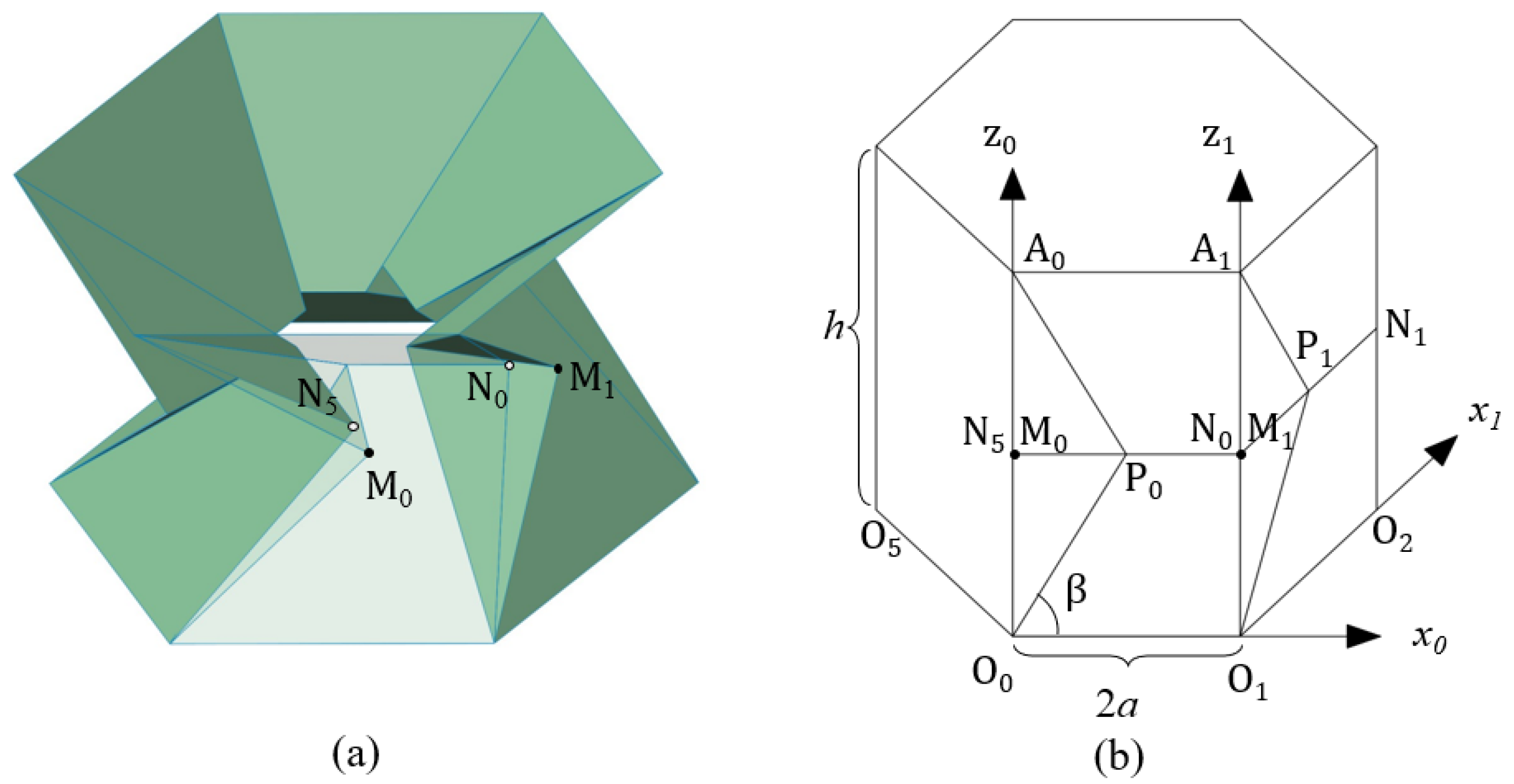
Figure 10.
The trajectories of the connection’s midpoints on the x–y plane.
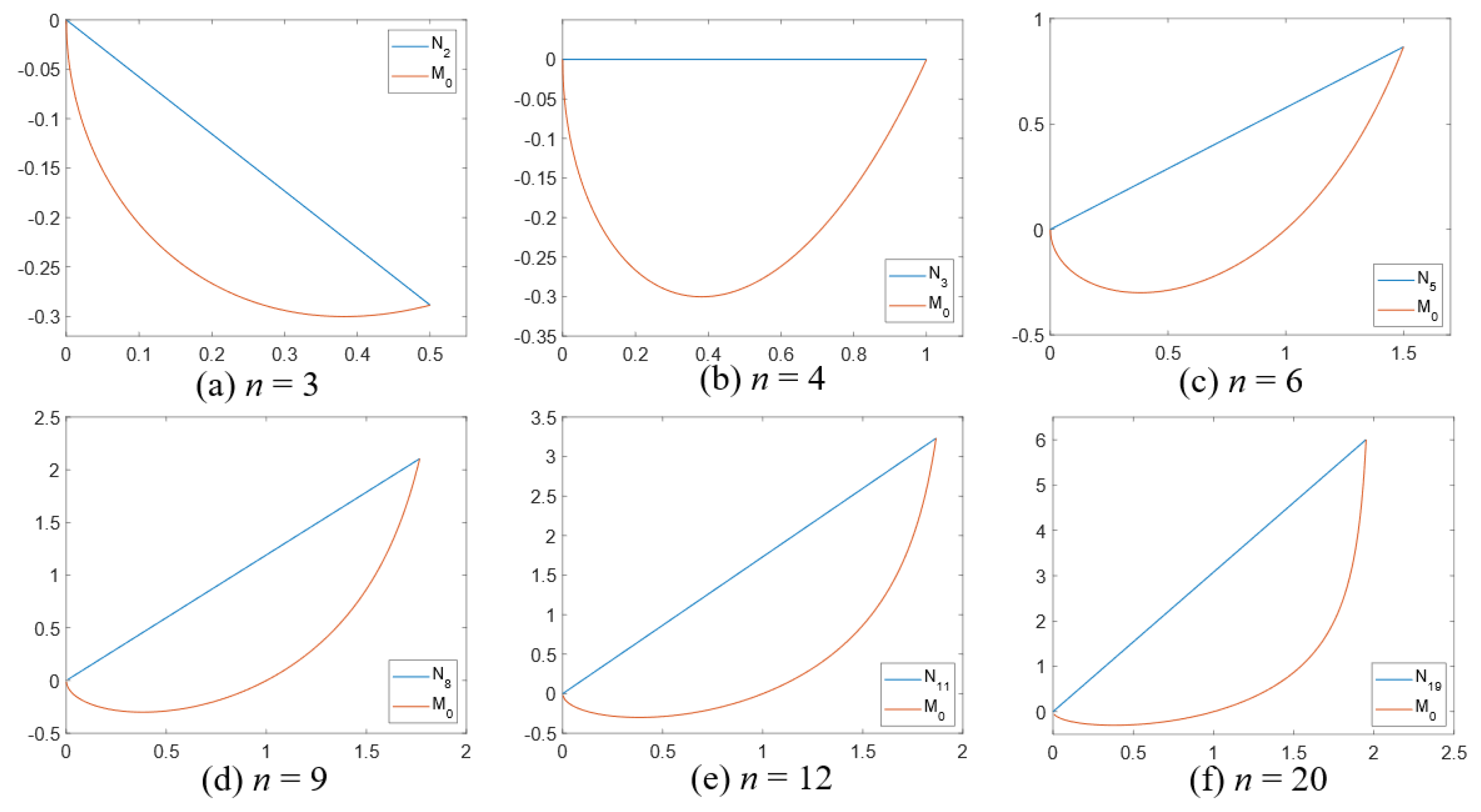
Figure 11.
(a) FEA simulation folding process. (b) The trajectories of point under the FEA results and the rigidly foldable kirigami counterpart result. (n = 6).
Figure 11.
(a) FEA simulation folding process. (b) The trajectories of point under the FEA results and the rigidly foldable kirigami counterpart result. (n = 6).
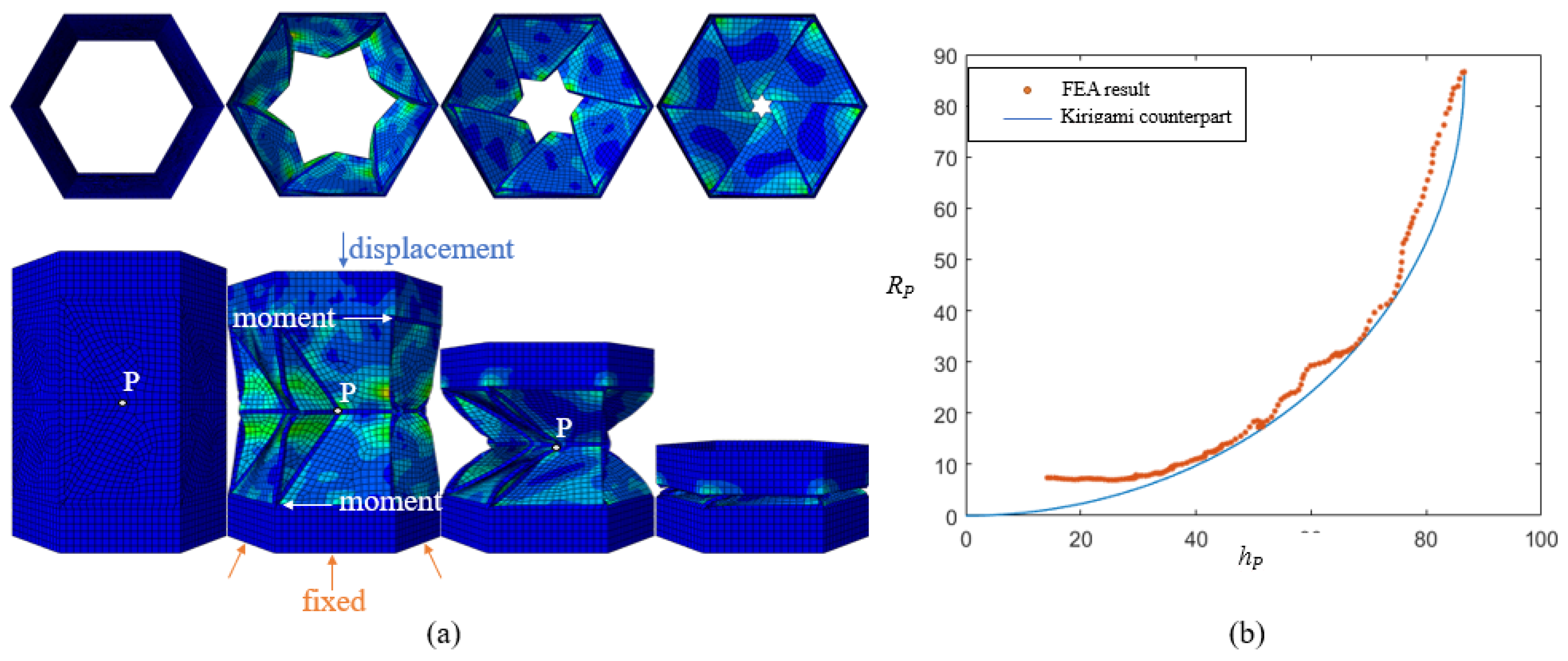
Figure 12.
Simplified rigid RC-ori prototype made by 3D printer. (n = 6) (a–c) is the folding process of a paper model. (d–f) is the folding process of a Solidworks model. (g–i) is the folding process of a printed model connected by flexible lines. https://youtube.com/shorts/E0uF6XN1cNQ (accessed on 25 August 2022) (video).

Figure 13.
(a) Half-folded state of the RC-ori structure (kirigami counterpart). (b) The relationship between unfolded length and cross-section area. (n = 6).
Figure 13.
(a) Half-folded state of the RC-ori structure (kirigami counterpart). (b) The relationship between unfolded length and cross-section area. (n = 6).

Figure 14.
Top view of the three situations of the opening area during the folding process. ().

Figure 15.
Comparison of the relationship between S and h of the RC-ori structure and the Kresling structure. (n = 6).
Figure 15.
Comparison of the relationship between S and h of the RC-ori structure and the Kresling structure. (n = 6).

Table 1.
The position of each point in the coordinates.
| Point | x | y | z |
|---|---|---|---|
| 0 | 0 | h | |
| 2a | 0 | h | |
| h/2 | |||
| a | h/2 | ||
| 2a | h/2 | ||
| 2a | 0 | 0 | |
| 0 | 0 | 0 |
Publisher’s Note: MDPI stays neutral with regard to jurisdictional claims in published maps and institutional affiliations. |
© 2022 by the authors. Licensee MDPI, Basel, Switzerland. This article is an open access article distributed under the terms and conditions of the Creative Commons Attribution (CC BY) license (https://creativecommons.org/licenses/by/4.0/).
Share and Cite
MDPI and ACS Style
Ye, S.; Zhao, P.; Zhao, Y.; Kavousi, F.; Feng, H.; Hao, G. A Novel Radially Closable Tubular Origami Structure (RC-ori) for Valves. Actuators 2022, 11, 243. https://doi.org/10.3390/act11090243
AMA Style
Ye S, Zhao P, Zhao Y, Kavousi F, Feng H, Hao G. A Novel Radially Closable Tubular Origami Structure (RC-ori) for Valves. Actuators. 2022; 11(9):243. https://doi.org/10.3390/act11090243
Chicago/Turabian StyleYe, Siyuan, Pengyuan Zhao, Yinjun Zhao, Fatemeh Kavousi, Huijuan Feng, and Guangbo Hao. 2022. "A Novel Radially Closable Tubular Origami Structure (RC-ori) for Valves" Actuators 11, no. 9: 243. https://doi.org/10.3390/act11090243
Note that from the first issue of 2016, this journal uses article numbers instead of page numbers. See further details here.