1. Introduction
Lower energy use and higher comfort in a building can be achieved if the building is allowed to interact with its surrounding in a smart way. This can for instance be to utilize solar radiation, passively through the windows or actively via a solar collector. It can be an efficient day lighting design or it can be the use of natural or hybrid ventilation. The natural ventilation technique is driven by thermal buoyancy force and wind induced force. The hybrid ventilation technique utilizes these forces to the maximum extent and when it is insufficient, it is complemented with a fan [
1]. This, at the same time, results in a high degree of utilization of the natural driving forces and a high reliability. However, these systems normally lack the possibility to recover any of the energy that disappears with the outgoing ventilation air. In cold climates this will result in a high energy need and low comfort due to draughts. One way to solve this is to use so-called mechanical ventilation with heat recovery. This enables a heat recovery efficiency of the outgoing ventilation air of about 75% [
2]. At the same time, the air-handling units preheat the incoming air, which results in a reduced draught. However, these types of units use a considerable amount of electrical energy to run the fans in the system. The high energy use by the fans is connected to the high pressure drop in the air-to-air heat exchangers that transfer the energy from the outgoing to the incoming air. At the same time, the units have a risk of creating a disturbing noise from the ventilation system. Recently, there have been reports about heat exchangers designed to work in natural or hybrid ventilation systems [
3,
4]. The heat exchangers have a very low pressure drop, down to or even less than 1 Pa, and at the same time high heat transfer rates in the units. Heat recovery efficiencies of approximately 70%–80% have been reported. These are instantaneous values. Average values from a full year including frost problems etc. are not available. These heat exchangers may enable a new kind of ventilation systems with heat recovery. If the pressure drop can be kept low, there is a possibility to create natural or hybrid ventilation systems including heat recovery. This also means that it could be possible to build passive houses or other types of low energy buildings with a natural or a hybrid ventilation system. One way to construct a hybrid ventilation system with heat recovery is to use two heat exchangers, one located at the bottom of the building and one at the top of the roof. The energy that is recovered from the roof heat exchanger is pumped in a brine connected system to the heat exchanger at the bottom of the building where the energy is used to preheat the incoming ventilation air. This type of ventilation system, reviewed in [
5], is known as run-around heat recovery system. Using such a brine connected system also makes it possible to connect other heat sources such as ground heat storage. Typically, the ground collector is made up of plastic tubes. Different ways of connecting the plastic tube of the collector are discussed in [
6].
Other interesting ventilation and heating techniques have been presented. Zhai [
7] and Khedari [
8] both investigated natural ventilation of buildings induced by roof integrated solar collectors. The aim of this paper is to determine the energy implications of a hybrid ventilation system with heat recovery based on simulations for a low energy and a traditional one-family house.
2. Method
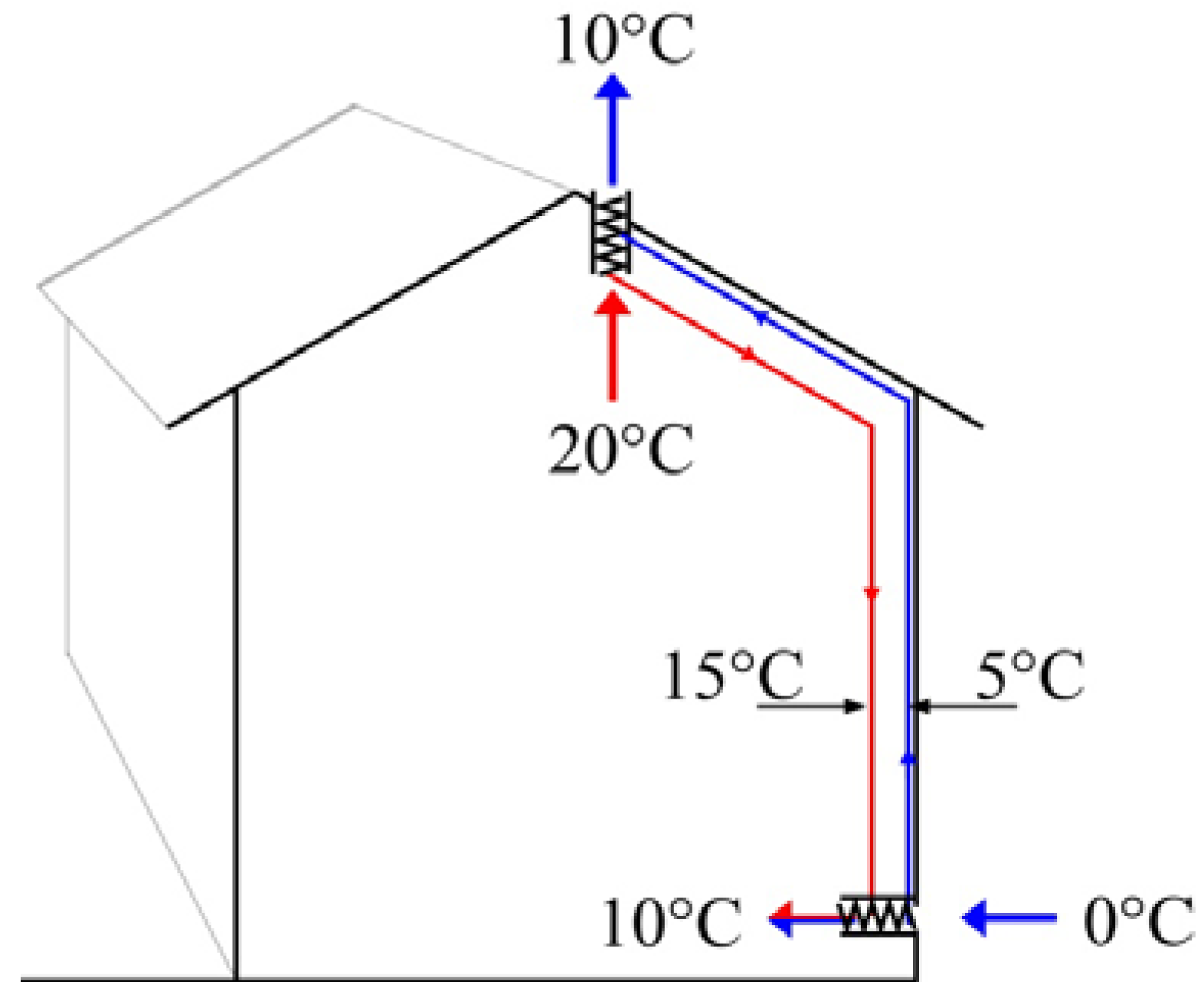
One possible way to build a hybrid ventilation system with heat recovery is to use two water-to-air heat exchangers connected in series. This is illustrated in
Figure 1. The temperatures shown in the figure illustrate the principle of the system. Cold outdoor air is heated as it is let through the heat exchanger at the bottom of the building. The temperature of the air is increased from e.g., 0 °C to 10 °C. At the same time, the brine temperature is reduced from 15 °C to 5 °C. When the hot indoor air passes through the roof, it is cooled in the roof heat exchanger. The temperature drops from 20 °C to 10 °C. At the same time, the brine temperature is increased from 5 °C to 15 °C, the circuit is completed and the process can be repeated. Since the temperatures involved in the processes are low, there is a possibility to use innovative heat sources to improve the system performance. One alternative is to use the ground as a heat source. After the brine has been cooled in the heat exchanger at the bottom of the building, it is run through the ground collector to increase the temperature. During cold periods, the brine can reach sub zero temperatures after passing through the heat exchanger at the bottom of the building. During these periods, the ground can supply the ventilation system with large amounts of energy. Alternatively, the system can utilize energy from the waste water from the building. In order to maximize the potential in such system, the waste water can be stored in a tank. In this way, the energy can be stored and utilized over a large time frame. The waste water heat recovery system is discussed in more detail in
Table 1.
However, the interaction between, for instance, the ground collector and the ventilation system is complex. If the ground collector transfers energy from the ground to the brine, and in this way increases the temperature in the brine circuit, there will be less heat recovered from the roof heat exchanger. This will lower the fraction of recovered energy in the ventilation system. The saving potential is thus difficult to estimate without simulations. Mechanical ventilation systems can also be equipped with a ground collector, although this is not usually done. In principle, it is possible to let the air pass into the ground for preheating before it is admitted into the building. Different innovative techniques have been reported to preheat air for different uses. Pinel
et al. [
9] reviewed different types of seasonal storage techniques. These methods are, however, not simulated in this paper. The analysis in this article is based on simulations using the program TRNSYS [
10] for a one-family house with a floor area of 150 m². The building is a one and a half storey building with a total volume of 390 m³. The different investigated cases are discussed and illustrated in
Table 2. All systems were simulated with two different levels of insulation, this is discussed in more detail in
Table 1. The input data for the simulation is also presented in
Table 1. All systems are equipped with a hot water storage tank that supplies the domestic hot water. The air flows are assumed to be exactly what is required for both the hybrid ventilation and the mechanical ventilation.
Figure 1.
The principle of the proposed hybrid ventilation system with heat recovery.
Figure 1.
The principle of the proposed hybrid ventilation system with heat recovery.
Table 1.
Input data for the TRNSYS-deck.
Table 1.
Input data for the TRNSYS-deck.
| Physical object/control | TRNSYS type | Description |
|---|
| Building | Type 88 | The average U-value of the low energy building was 0.215 W/m²K. This value was chosen to simulate a passive house. The standard insulated building had an average U-value of 0.5 W/m²K. The thermal capacitance of the buildings was set to 40 MJ/K. This corresponds to approximately 100 m² concrete floor, 100 m² brick wall and it includes interior material and the roof. |
| Internal gains | Equation | Windows facing south (6.5 m² glazing area), west (6.5 m²), north (4 m²) and east (4 m²) with a g-value of 55% were installed in the building. This gives a glazing to floor area ratio of approximately 14%, which is a typical value. The transmitted solar radiation was treated as internal gains of the building. The thermal losses from the main storage tank and heat from people and electrical equipment were also added as internal gains. The gain from people and electricity was set to 500 W continuously. According to standard [11] the internal gains from people and electricity are 4 W/m². 500 W thus corresponds to a 125 m² building. This is somewhat lower than the actual size of the building. This was chosen in order to include effects of using low energy household appliances. |
| Main storage tank | Type 4a | The hot water storage tank was set to a volume of 400 l and was assumed to have a heat loss factor of 0.83 W/m²K, with an area of approximately 1.7 m². The heater was set to 60 °C. |
| Waste water storage tank | Type 534 | The waste water heat recovery tank was set to 150 L. The tank is equipped with immersed heat exchangers for the domestic hot water and for the ventilation circuit. The waste water storage tank is assumed to be located outside the building. Hence, the thermal loss from the tank is not utilized by the building. A small test with a waste water heat exchanger was set up in a one family house. The system consists of two series connected waste water tanks with built in heat exchangers. The heat exchangers were made up from corrugated stainless steel pipes with a total length of 17 m. These measurements were used to calibrate the TRNSYS component later used in the simulations presented in this article. The measurements show e.g. that having balanced flow, i.e., the same flow for the entering waste water as for the hot water at 3L/min results in a heat recovery rate of 66% from the waste water. |
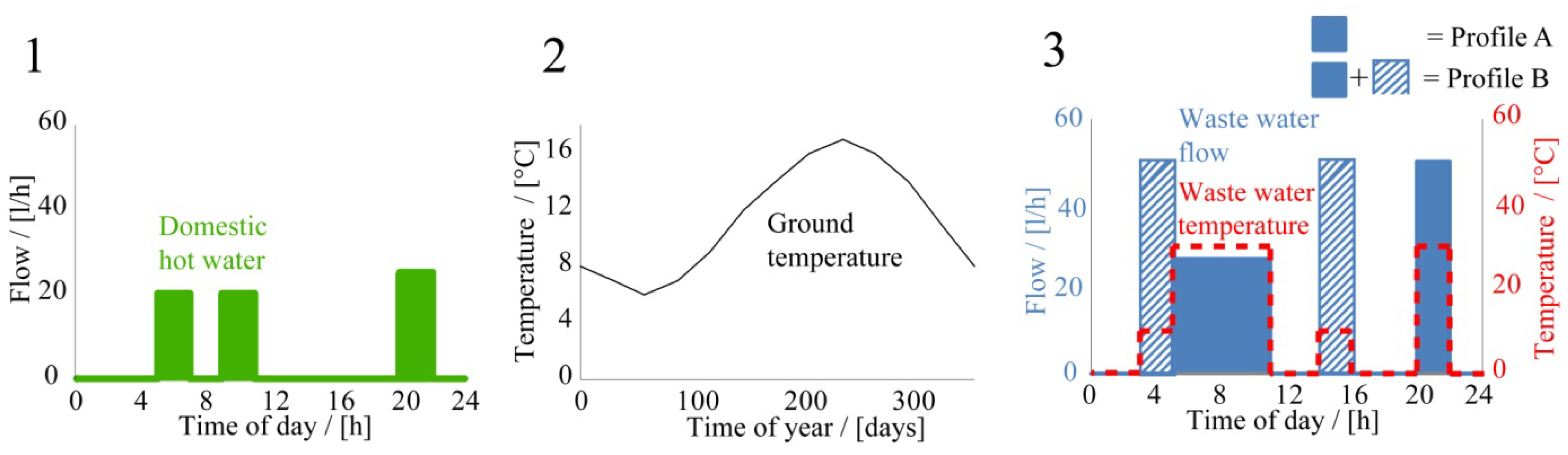
| Temperature and flow profiles | Equation | The hot water consumption profile shown in Figure 2 is a simplification of the findings of Widén et al. 2009 [12]. During the morning, the hot water consumption is 20 L/h between 5:00 h and 7:00 h and between 9:00 h and 11:00 h. During 20:00 h–22:00 h, the consumption is 25 L/h. This means that the household consumes 130 L of 60 °C hot water a day. This hot water is mixed with cold water in order to get lukewarm water for the household needs. The inlet water temperature to the storage tank as a function of day number can be seen in the second figure [13]. The numbers are given by the local supplier of fresh water in the southeastern part of Sweden. The third figure to the right shows the waste water. The waste water is assumed to come from showers, sinks and the kitchen, i.e., the toilets are not included. The waste water flow in L/h is in blue and its temperature in dashed red. The difference between the domestic hot water profile and the waste water flow profile was chosen to include non perfect overlapping. This can for instance be when someone empties a bathtub. This causes a large waste water flow but there might not be a flow in the opposite direction, i.e., incoming water, thus the difference in simultaneity. Simulations were performed for two different flow profiles, one with only the filled blue squares, labeled Profile A, and one with the filled and the striped squares, labeled B. The simulation that included the striped squares was performed in order to investigate the sensitivity of the flow profile. As can be seen, the difference is that during the periods indicated with striped squares, cold water is let into the waste water tank. This can, for instance, be if cold water is run in the morning to flush the pipes in the building. The total volume of waste water is assumed to be twice the volume of the domestic hot water use for flow Profile A. Flow Profile B is the same as profile A but with an extra volume of 100 L water at 10 °C. The temperature of the waste water is assumed to be a mixture of equal parts of 10 °C and 50 °C water, i.e., 30 °C. |
| Ground collector | Equation | The ground collector was simulated using the ground temperature profile shown in Figure 2, the illustration in the middle. The temperature of the outgoing water from the ground collector is assumed to have the ground temperature. This means that the heat transfer is without resistance and that the size of the collector is large enough not to be affected by the energy removed from it. This is a simplification and the results should be viewed as an indication of the impact with ground source heat storage in this type of system. |
| Weather data | Type 109 | The weather data is data from Malmö in the south of Sweden. The weather data was obtained from Meteonorm. |
| Heat exchangers | Type 5b | The brine in the ventilation circuit was assumed to be water. The heat transfer coefficient was varied resulting in efficiencies between 43% and 86%. The total efficiency of the two in series connected heat exchangers is less than the efficiency of a single unit. For instance, placing two heat exchangers with 86% efficiency as shown in Figure 1 will result in a system efficiency of approximately 75%. |
| Ventilation system | Equation | The mechanical ventilation with heat recovery was simulated using an “equation” type. It is assumed that the efficiency is always 75%. The ventilation flow rate for all cases was set to 234 kg/h, which is approximately equal to an air change rate of 0.5 changes per hour. This value was chosen in order to meet the requirements of the Swedish Building code [14]. The ventilation flow rate was increased by a factor of two during periods with an indoor temperature that exceeded 27 °C. This was done in order to avoid excessive heat storage in the construction. |
Figure 2.
The (1) shows the domestic hot water flow profile; (2) shows the ground temperature, i.e., the temperature of the inlet water; (3) shows the flow rate in blue and the temperature of the waste water in red.
Figure 2.
The (1) shows the domestic hot water flow profile; (2) shows the ground temperature, i.e., the temperature of the inlet water; (3) shows the flow rate in blue and the temperature of the waste water in red.
Table 2.
The different investigated cases. All systems are equipped with a hot water storage tank that supplies the domestic hot water.
3. Results
All results in this article are based on TRNSYS simulations.
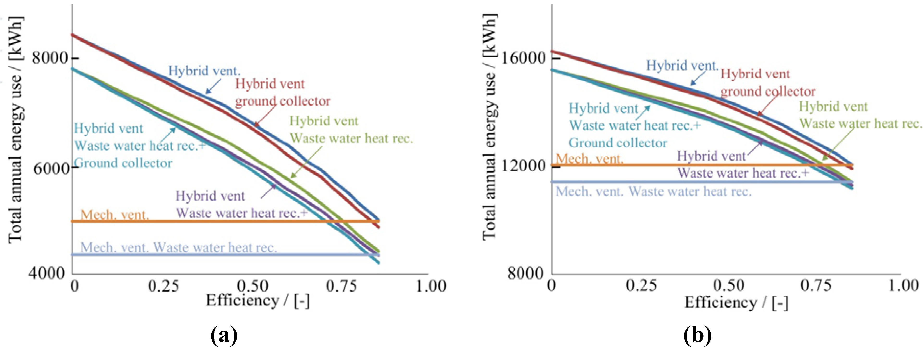
Figure 3 shows the total annual energy need for space heating and domestic hot water as a function of the efficiency of each of the heat exchangers. The left figure shows the results for the low energy building and the right one for the standard insulated building. The dark blue graph,
i.e., the uppermost, is for the hybrid ventilation system,
i.e., simulation Case 2a. The red graph is simulation Case 3c,
i.e., the hybrid ventilation system equipped with a ground collector. The graph shows that the ground collector has almost no effect if the efficiency of the heat exchangers is low. The green line represents the simulation Case 3a,
i.e., hybrid ventilation and waste water heat recovery. Installation of waste water heat recovery lowers the annual energy need by approximately 600 kWh. The simulations were performed using waste water Profile B. The purple line represents simulation Case 3b and the light blue line,
i.e., the lowermost one, simulation Case 4. The orange and the light purple horizontal lines show the annual energy need for simulation Cases 2b and 3d,
i.e., mechanical ventilation with heat recovery with and without the waste water heat recovery. The result does not include the energy needed to run the fans for the ventilation. The results are presented as lines even though the performance is independent of the efficiency of the heat exchanger for the hybrid ventilation.
Figure 3.
The total energy need, i.e., space and domestic hot water heating, for the different simulations as a function of the efficiency of each of the heat exchangers for the ventilation. (a) is the low energy building; and (b) is the standard insulated building.
Figure 3.
The total energy need, i.e., space and domestic hot water heating, for the different simulations as a function of the efficiency of each of the heat exchangers for the ventilation. (a) is the low energy building; and (b) is the standard insulated building.
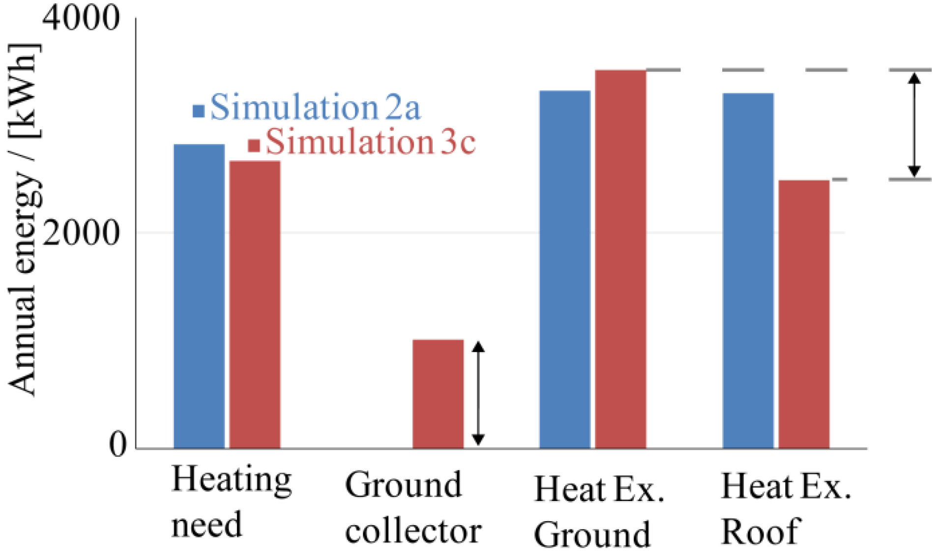
Figure 4 illustrates the annual energy flow for a low energy building. The blue bars represent simulation Case 2a and the red ones simulation Case 3c. This means that the hybrid ventilation with heat recovery system is compared with an equal system, but with the difference that a ground collector has been added. The first bars show the annual heating need for the two systems. The difference between the two systems is approximately 150 kWh annually. The second group, with only one bar, is the annual energy transferred from the ground to the brine by the ground collector. This is approximately 1000 kWh annually. The third group is the energy delivered to the incoming air by the heat exchanger located at the bottom of the building. Simulation Case 3c delivered approximately 200 kWh more than simulation Case 2a on an annual basis. The reason why the energy need is only reduced by 150 kWh annually when the heat exchangers deliver 200 kWh is that parts of this energy will not be used to lower the energy use. It will only be used to increase the overheating of the building. The fourth group shows the annual energy recovered from the outgoing ventilation air by the roof heat exchanger. The simulations are based on using a heat exchanger with an efficiency of approximately 75%.
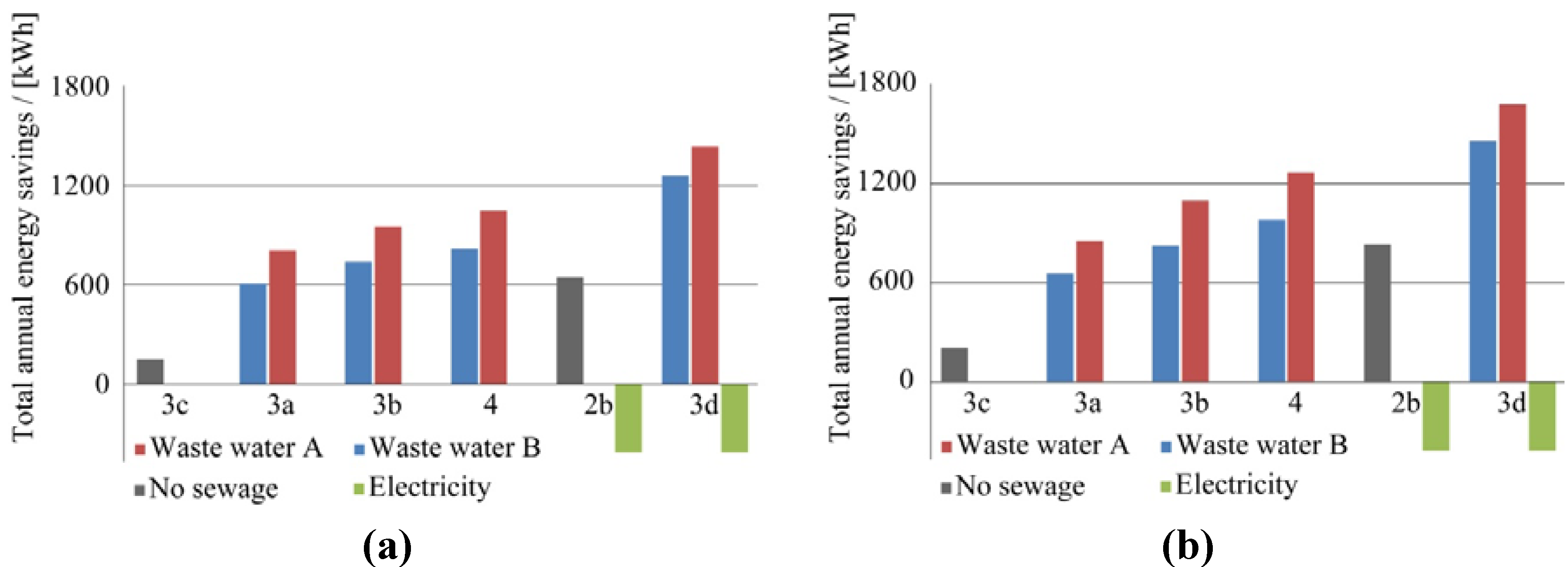
Figure 5 shows the saving potential between the different cases. All the simulation cases are built on using heat exchangers with a component efficiency of approximately 75%. The left figure is for the low energy building and the right one for a standard insulated building. The basis for the simulation is System 2a,
i.e., a hybrid ventilation system with heat recovery. The first bar is for simulation Case 3c. Installation of a ground collector saves about 150 kWh of energy per year. The second group of bars is for simulation Case 3a. The blue bar is for waste water flow Profile B and the red one for waste water flow Profile A. Installing a waste water heat recovery system lowers the annual energy need by approximately 600–800 kWh. The third group of bars is for System 3b. This case performs slightly better than Case 3a. The fourth group is for simulation Case 4. The fifth group is for Case 2b,
i.e., the mechanical ventilation with heat recovery without waste water heat recovery system. This system will use about 420 kWh more electrical energy compared with the hybrid ventilation systems. This is shown with the green bar. The electrical energy consumption for the hybrid ventilation system was estimated from temperature difference data from the simulation along with information on the fraction of time that the brine was being circulated. The support fan is assumed to have an annual average electrical power consumption of 4 W [
15]. The right bars are for Case 3d. This system is assumed to spend as much electrical energy as Case 2b. The waste water heat recovery system recovers approximately 700 kWh annually.
Figure 4.
The annual energy flows for a low energy building for two simulation cases, Case 2a in blue and Case 3c in red.
Figure 4.
The annual energy flows for a low energy building for two simulation cases, Case 2a in blue and Case 3c in red.
Figure 5.
The saving potential for the different systems for waste water flow Profiles A and B, see
Figure 2, (
a) are the results for the low energy building; and (
b) are the results for the standard insulated building.
Figure 5.
The saving potential for the different systems for waste water flow Profiles A and B, see
Figure 2, (
a) are the results for the low energy building; and (
b) are the results for the standard insulated building.
4. Conclusions
Figure 3 shows that the most important factor in the system is the efficiency of the heat exchangers. Also, there is a possibility to recover about 25% of the energy in the waste water using the kind of technique presented here. This technique can, however, be developed further for even larger energy savings. Two different waste water flow profiles were tested. This was carried out in order to investigate the sensitivity of different profiles. The waste water heat recovery system annually recovers about 200 kWh more with Profile A compared to Profile B. This is due to the cold water flow in Profile B that flushes the waste water tank, and thus a large amount of energy is lost before it can be recovered.
Figure 3,
Figure 5 show that inclusion of more energy sources in the ventilation heat recovery system, such as the ground collector or utilization of the waste water heat, has only minor effects on the annual performance. In
Figure 3 it can be seen that, for the hybrid ventilation system to perform as well as the mechanical ventilation system, the heat exchanger has to have an efficiency of about 86%. A heat recovery efficiency of 86% on a component level equals a system heat recovery rate of 75% [
4],
i.e., when both the roof and the heat exchanger at the bottom of the building are taken into account. This means that the need for auxiliary energy is the same for both systems. However, the mechanical ventilation system consumes more electrical energy. This is nothing unexpected but well worth pointing out.
In
Figure 5 it was shown that the mechanically ventilated system consumes approximately 400 kWh more electrical energy annually compared with the hybrid ventilation system. It should be noted that this energy has to be electrical energy. The energy needed for the heating and the domestic hot water discussed in this article could come from somewhere else, for instance from bio fuels, district heating or heat pumps. The 400 kWh of electrical energy for the fan should thus be considered extra valuable. The primary energy factor to be used can always be discussed. Often a factor of somewhere between 2.5 and 3 is used for electricity. If 2.5 is used, it means that the performance of the hybrid ventilation system can be 1000 kWh of heat worse than that of the mechanical ventilation with heat recovery system and still have the same total annual performance. In other words, a hybrid ventilation system equipped with heat exchangers with an efficiency of 65%–70% performs about the same on an annual basis as the mechanical ventilation system with heat recovery. During hotter periods, it may be possible to reduce or even turn off the ventilation system and instead rely on natural ventilation by means of open windows. This will lower the energy need for the ventilation system. This was, however, not included in any calculations.
One complication that has been left out in this discussion is the heat from the fans in the mechanical ventilation units. The electricity consumed by the fans will, if they are located downstream in the air flow movement, contribute to heating the building. However, far from all of the heat will be beneficial for the building. The heat produced during the summer will only add to overheating. The results in this article assume a mechanical ventilation unit with a 75% heat recovery rate. The electrical energy consumed by the fans is assumed to be included in these 75%.
If the electrical energy consumed by the fans is included in the annual average heat recovery rate for the ventilation unit, it will become beneficial to use inefficient fans. These fans consume and thus create large amounts of energy. This energy, transported to the air, will increase the effective heat recovery rate. Thus, units with high electricity consumption will appear to perform better.
Figure 3 shows that the ground collector had almost no effect if the efficiency of the heat exchangers was low. This can be understood by a more detailed investigation of the temperatures of the brine that is let into the ground collector. If a low efficiency heat exchanger is used for the inlet air, the brine temperature is not cooled enough to be able to utilize the relatively low temperatures in the ground. The high efficiency heat exchanger cools the brine more efficiently, which leads to the possibility to extract energy from the ground. Since the ground temperature is in the range of 6–8 °C during the winter the brine has to be cooled to temperatures below this in order to be able to gain energy from it. Simultaneously the energy savings are sparse even for higher heat exchanger efficiencies. This is explained by
Figure 4, which shows a large drop in the extracted thermal energy from the roof heat exchanger when the ground source was installed. This is explained by the brine already being heated as it arrives at the roof exchanger. There is simply less energy that can be recovered since the temperature has risen already.
One factor that was omitted in this investigation is the risk of having frost on the exchanger. As the outgoing humidified indoor air is let trough the heat exchanger at the roof the air is cooled down. When the temperature falls below the dew point, water drops will start to form on the surface. If the temperature continues to drop, water will start dripping from the exchanger. This is a technical issue that needs to be addressed if this system is to be commercialized. If the temperature is lowered even further there is a risk of frost developing on the heat exchanger. This has the potential to completely block the transport of air in the system and severely reduce the heat exchanger efficiency. One possible solution is to use a ground collector. The ground collector has the potential to increase the brine temperature to temperatures above zero. If the brine is above zero, there is no risk of getting frost on the heat exchanger. This means that a ground collector can be motivated even though the benefits from an energy point of view are limited.
Still there are many questions that need to be answered for this hybrid ventilation system.
Mechanisms to control the hybrid air flow rate. The air flow rate needs to be controlled in both directions, both to ensure that the ventilation is large enough and also to avoid excessive ventilation. The latter can typically occur during windy conditions when the air pressure is higher on one side of the building.
The heat exchanger surfaces need cleaning. Mechanical ventilation units are normally equipped with a filter. This filter prevents the heat exchanger surfaces from getting dirty. However, the pressure drop over the filter is typically too large for a hybrid ventilation system. One alternative is to construct the heat exchanger in such way that it allows for cleaning. This is possible since the structures in the heat exchanger are in the order of centimeters [
4] and not millimeters as in the case of the heat exchangers of mechanical systems.
The brine flow rate needs to be controlled. The ventilation system could be made up of many heat exchangers located in different rooms. The flow rate to each of these heat exchangers needs to be controlled to assure a balanced flow. One way of designing this type of system is to have one heat exchanger in each room where the ventilation air is intended to come in and one larger heat exchanger at the top of the roof where all the heat is recovered. The heated brine is pumped to the different rooms.
The design of the ventilation system must be considered to avoid blocking of exhausted air, as this would create a pressure drop and lower ventilation rates for the whole building.
Noise level. The hard constraints on the pressure drop make it difficult to use a silencer. This will have consequences on the level of noise transmitted from the outside of the building through the fresh air intake. However, at the same time, there will be less noise due to fans running the system.
Constraints on the architecture. The system might not be suitable for all types of buildings. This has to be investigated from building to building. At the same time, this type of heat recovery system, where the old contaminated air does not meet the fresh incoming air, is suitable when cross contamination has to be avoided. This can for instance be the case for ventilation of laboratories.
In the calculation example of this article the height difference between the air inlet and the outlet is assumed to be 10 m. If the height difference is substantially lower, there might not be enough pressure to run the ventilation system. The complementary fan would have to run more frequently. However, if the height is around 10 m, the investigated ventilation system could be used in future low energy buildings such as passive houses and net zero energy buildings. There are also alternative ways to enhance the ventilation flow rate. Different types of solar chimneys have been suggested. Zhai [
16] reviewed the field of solar chimneys and Khan [
17] reviewed different wind driven techniques for ventilation. Both of these types of techniques could be used to improve the hybrid ventilation technique.
There is also a possibility to use the ventilation system when old buildings with passive stack ventilation are energy renovated. The question how well this type of ventilation system can work in old buildings is very difficult to answer. If the building is ventilated by opening windows and there are no exhaust air ducts, it will be difficult to implement the ventilation system discussed in this article. However, it can be advantageous with this type of system to renovate old buildings with exhaust ventilation systems where the air flow pattern in the building is unchanged. If the old holes in the outer walls are used for the fresh air supply, the distribution of the air inside the building is not altered. The proposed ventilation system will thus not create places in the building with stagnant air. However, new holes through the exterior wall for the air inlet/outlet will most likely be needed to allow the heat exchanger to be installed. If new holes are introduced in the building in rooms or places previously not ventilated, there is a risk of altering the air movement. This can be a problem, but it can also be a solution for poorly functioning ventilation systems. The roof heat exchanger could be installed in the old ventilation system on the roof. This action would lower the peak power demand, lower the annual energy use and at the same time increase the comfort for the residents as the cold draught is reduced. During summer time when the passive stack effect disappears, the ventilation is carried out either with a complementary fan or with closed/opened windows. Opening windows for ventilation during the winter is still possible after retrofitting the old ventilation system. However, the heat recovery function will not work during the time with open windows.


