

Pressure Optimization in Pneumatic Interfaces Using a Single-Bay Seven-Story Infilled Reinforced Concrete Frame: Experimental and Numerical Investigation
 ,
,  and
and 
Abstract
:1. Introduction
2. Methodology
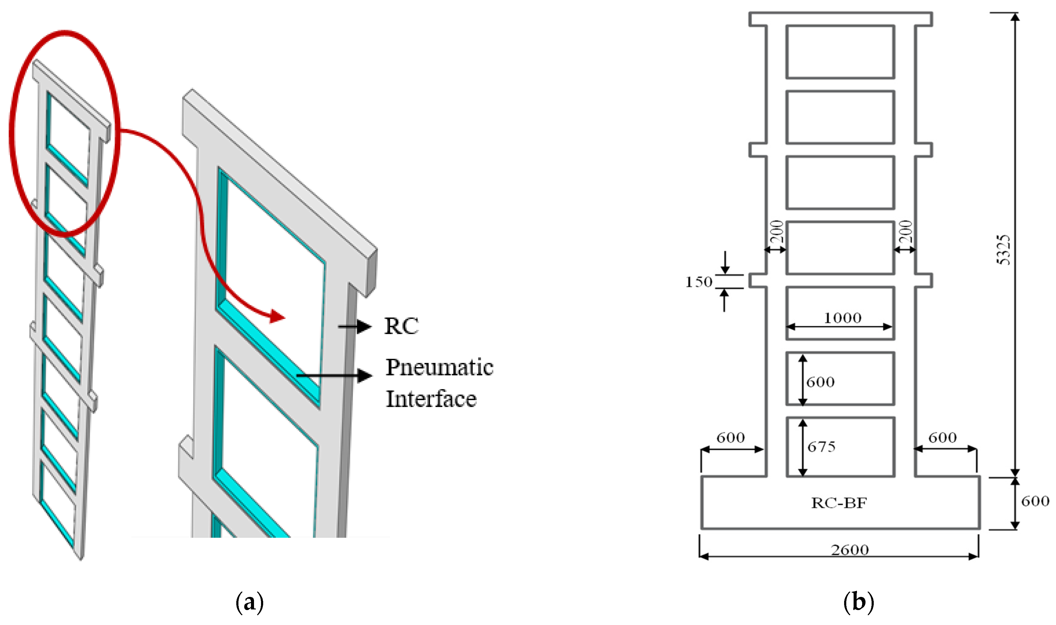
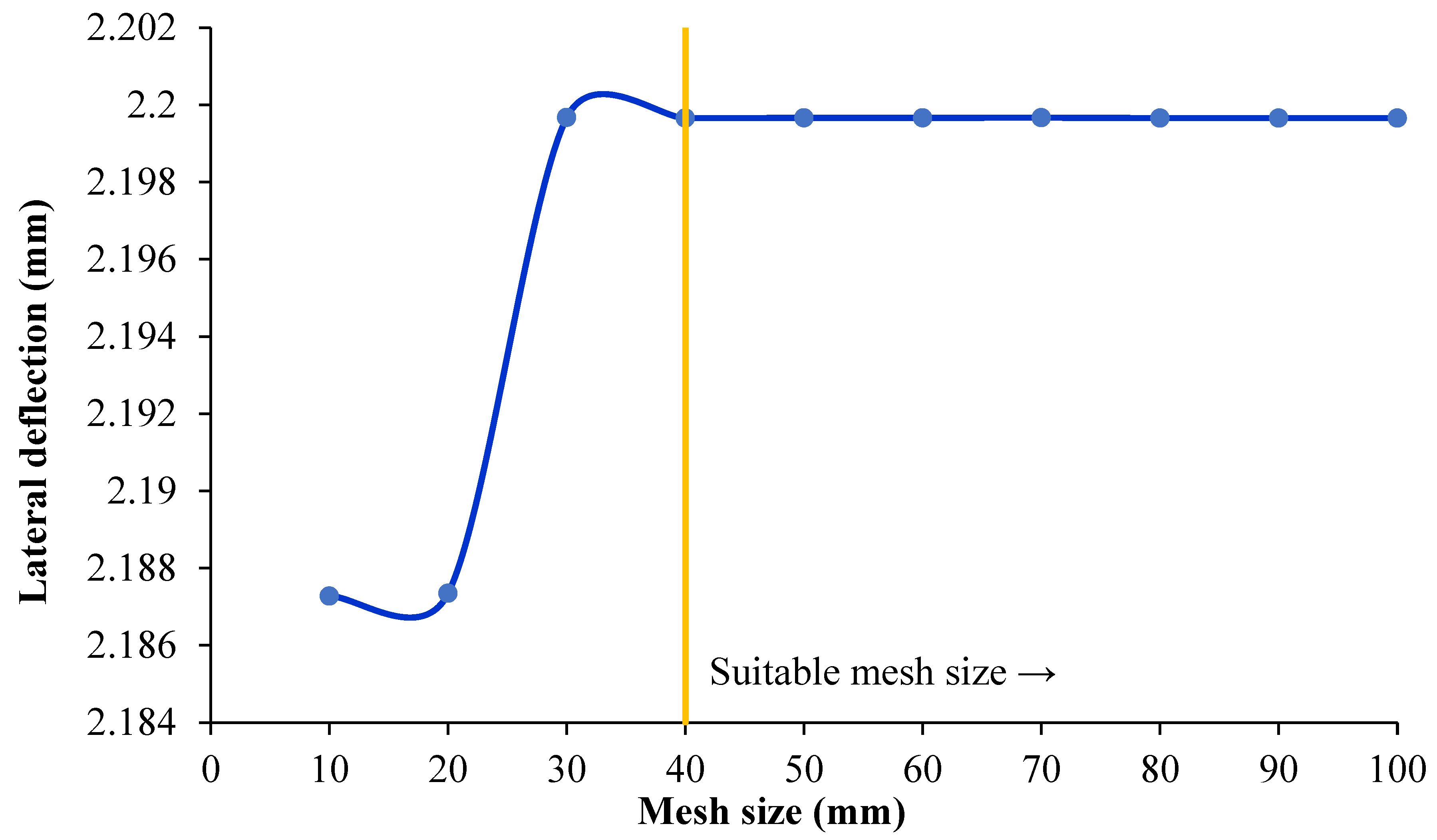
2.1. Modeling of Seven-Story Frames
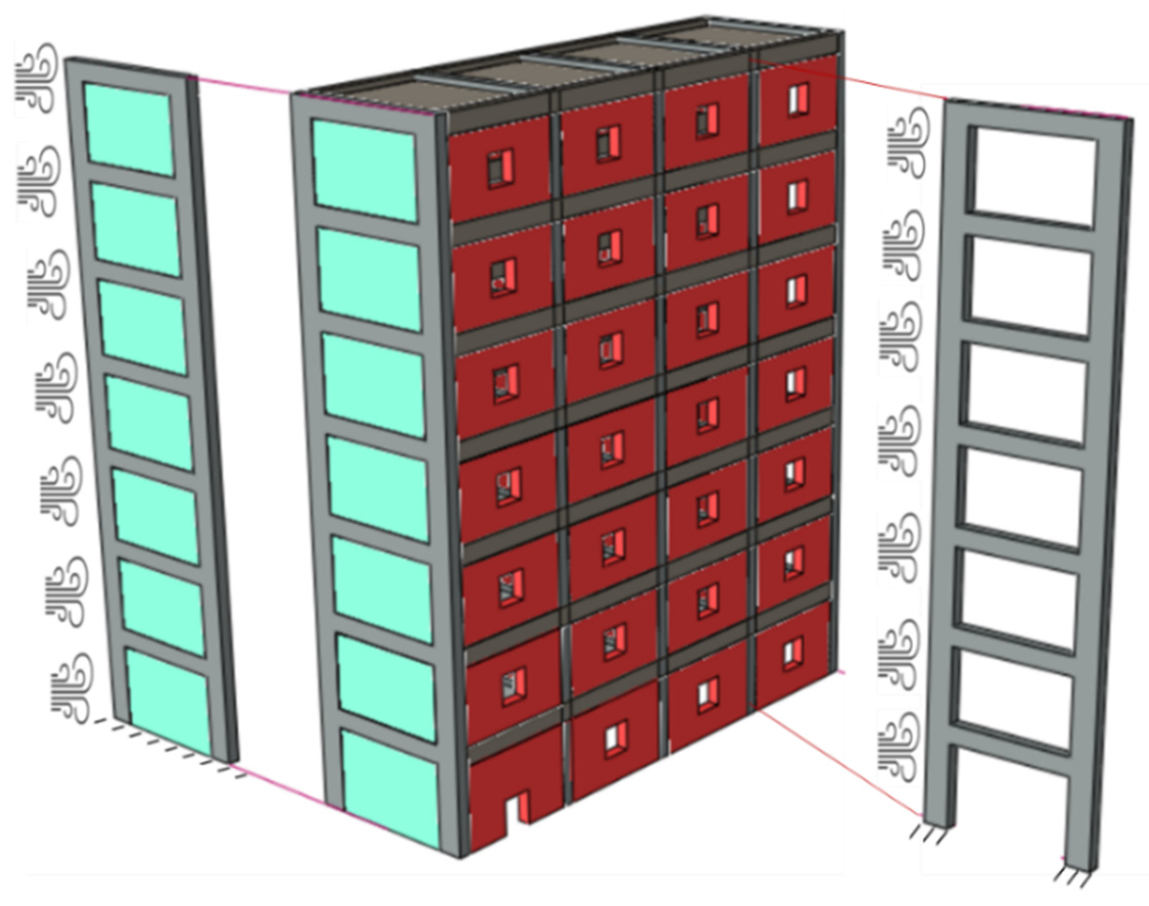
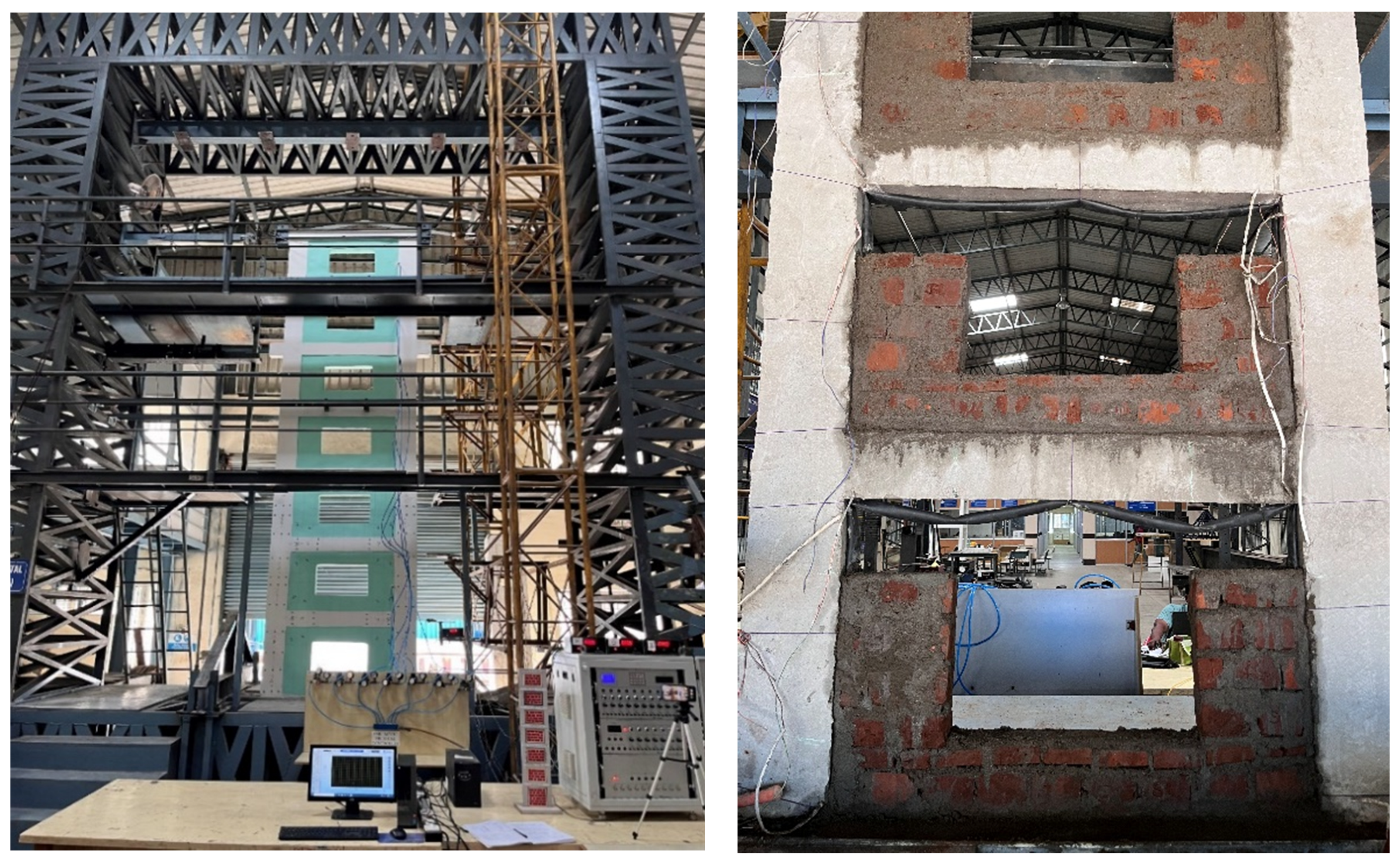
2.2. Experimental Setup of Seven Story Frames
3. Results and Discussion
3.1. PSI Optimization—Analytical Study
3.2. Story Optimization—Analytical Study
3.3. PSI Optimization—Experimental Study
3.4. Story Optimization—Experimental Study
4. Comparative Study
4.1. Displacement Study
4.2. Stiffness Study
4.3. Drift Study
5. Conclusions
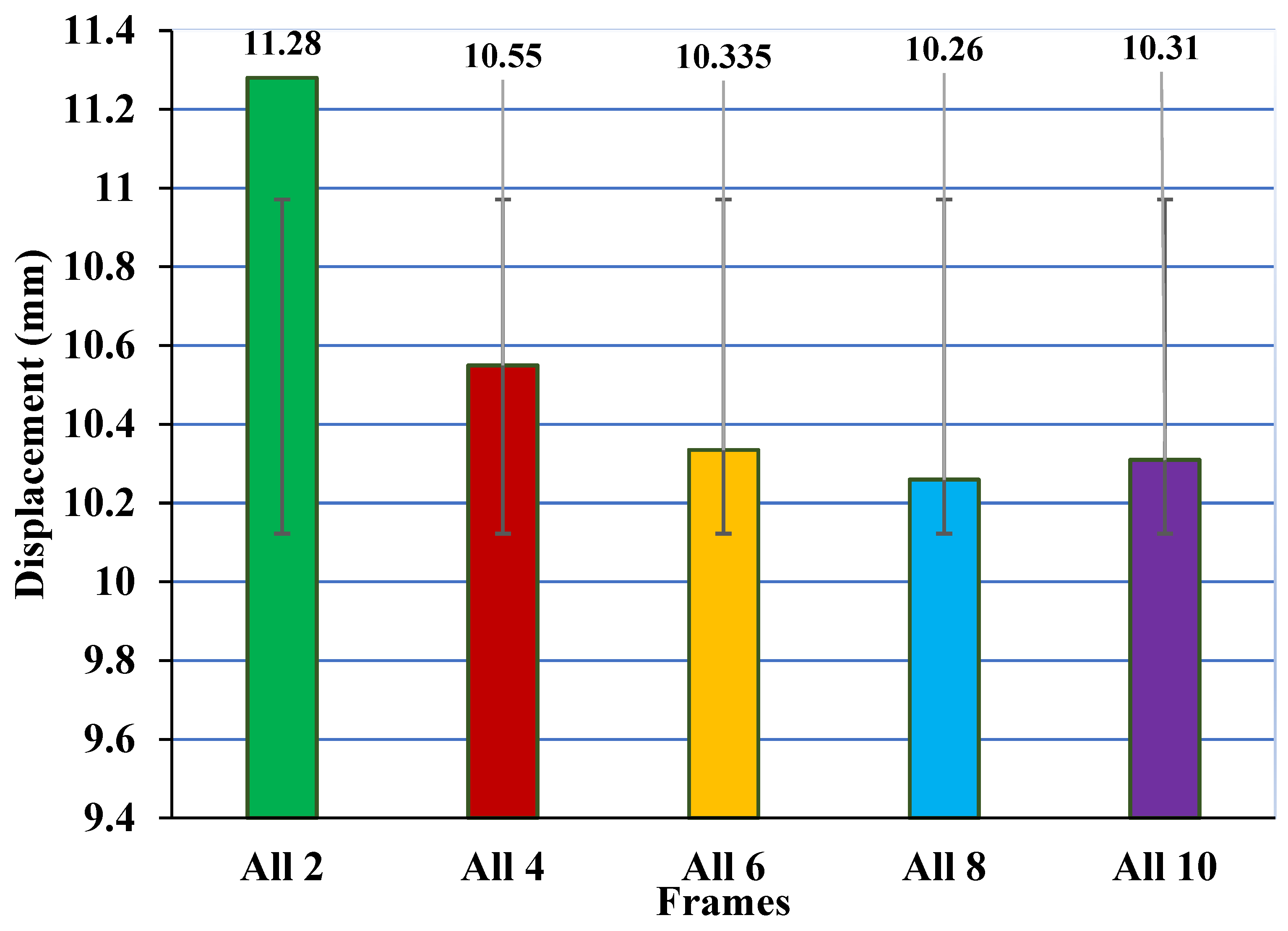
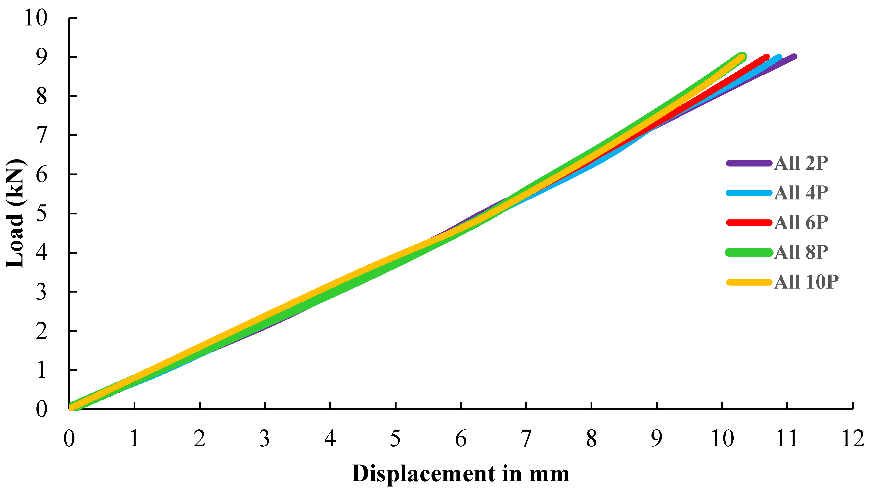
- Maintaining 8 PSI at all seven stories showed the least displacement when compared to other PSI dosages.
- There was a 0.73% difference between 6 PSI and 8 PSI and a 0.48% difference between 8 PSI and 10 PSI.
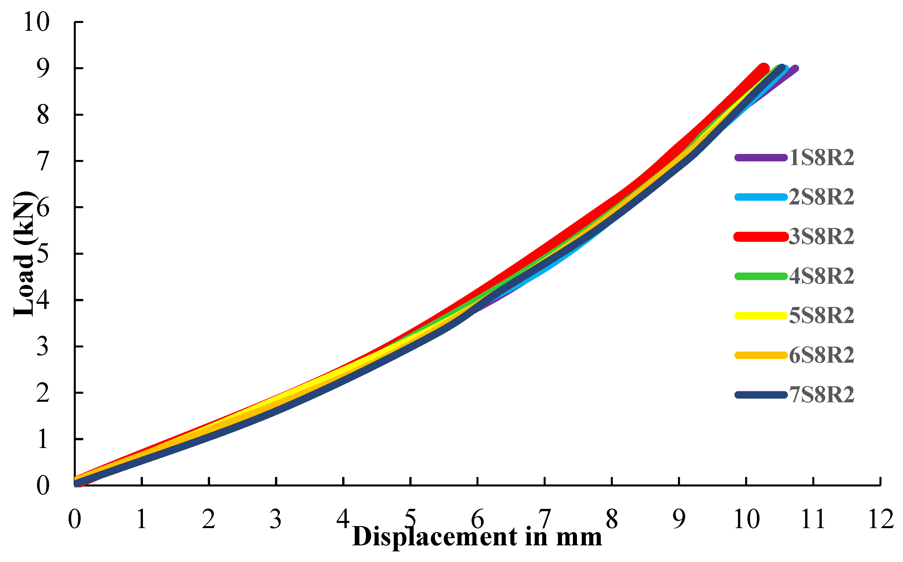
- The next smallest displacement profile was obtained with 3S8P, so the pressure at the third story alone was set to 8 PSI, and the other stories were set as 2 PSI for this study. There was a gradual increase in displacement of frames when the pressure was moved to the top story, which behaved as a conventional frame.
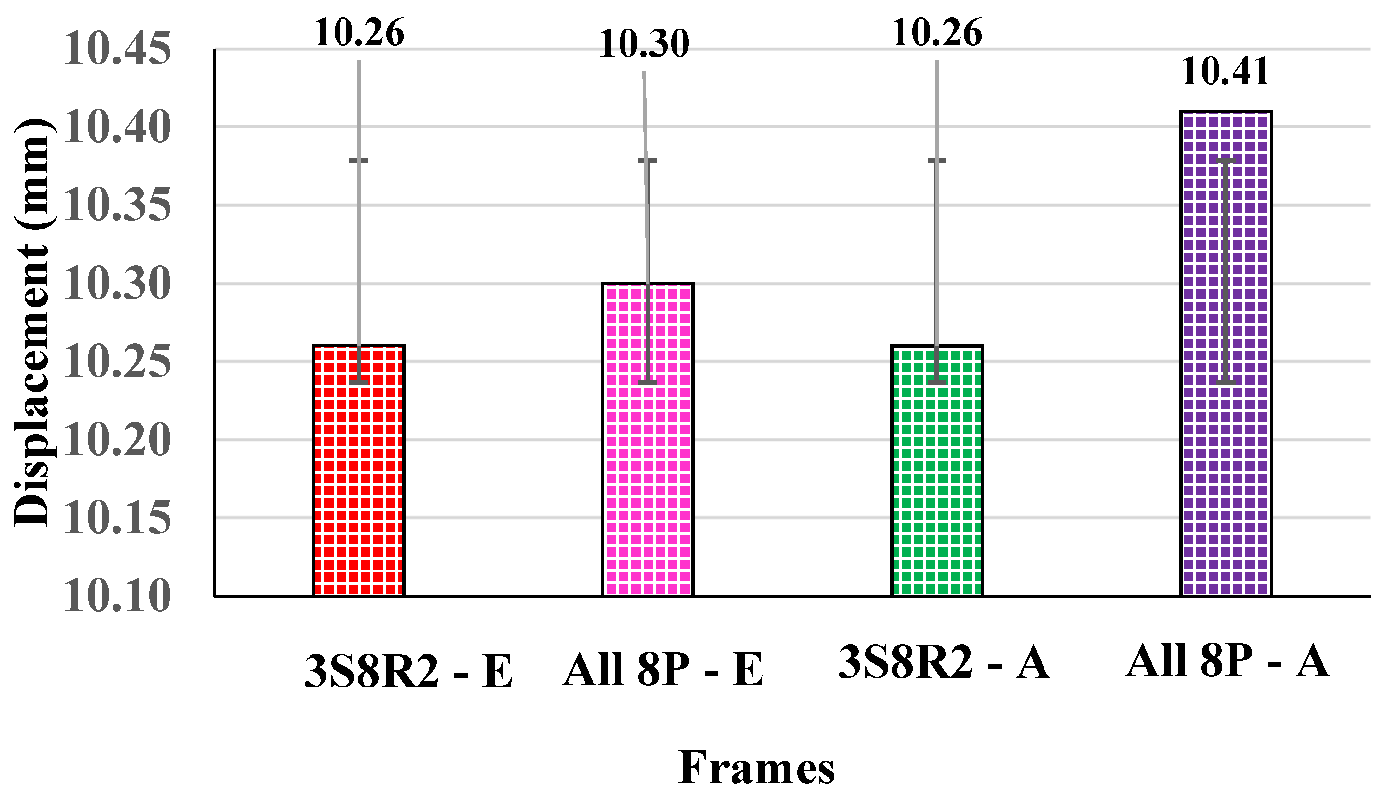
- The 3S8P and All 8P patterns achieve the least displacement when compared to the other variations. The difference was approximately 0.53% in the analytical study and 0.37% in the experimental work.
- The frame 3S8P achieved the minimum displacement; this was due to the critical position in which the plastic hinge formation occurs at the third story of the frame. Therefore, the pressure was applied at the third story to resist the lateral load, which directly reduced the displacement when compared to the other pressure patterns.
- The optimization was performed using both an experimental model and an analytical model, which had an error percentage of 0.61%.
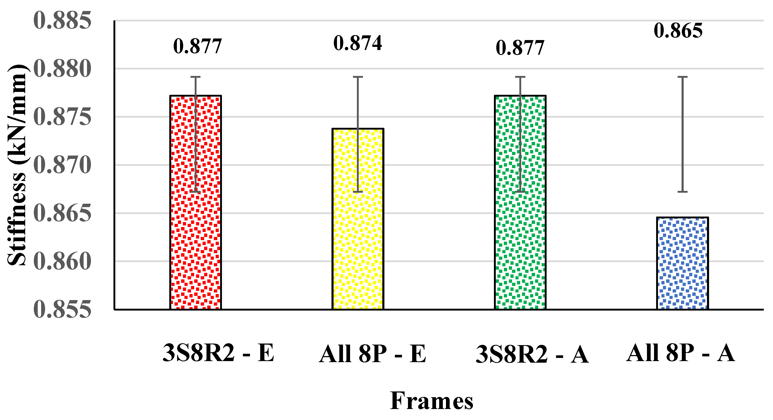
- There was a higher stiffness in 3S8R2 than in All 8P in both the experimental and analytical studies. The 3S8R2 frame was 0.34% times higher in stiffness than the All 8P frame experimentally.
- The stiffness was increased in the 3S8R2 pressure pattern frame compared to the other patterns due to the resistance of the lateral load by the pressure applied to the butyl rubber tubes.
- The drift ratios prove that there was a significant decrease in the drift of the 3S8R2 pressure pattern frame when compared to All 8P in both the experimental and analytical work. There was an improvement in stiffness that directly reflects a decreasing drift ratio, which caused the frame to not collapse and be more durable.
Author Contributions
Funding
Data Availability Statement
Acknowledgments
Conflicts of Interest
References
- Palyvou, C. Akrotiri Thera: Building Technics and Morphology in Late Cycladic Architecture. Ph.D. Thesis, School of Architecture, National Technical University of Athens, Athens, Greece, 1988. (In Greek). [Google Scholar]
- Tsakanika, E. The Structural Role of Timber in Masonry of the Palatial Architecture of Minoan Crete. Ph.D. Thesis, School of Architecture, National Technical University of Athens, Athens, Greece, 2007. (In Greek). [Google Scholar]
- Fang, B.; Hu, Z.; Shi, T.; Liu, Y.; Wang, X.; Yang, D.; Zhu, K.; Zhao, X.; Zhao, Z. Research progress on the properties and applications of magnesium phosphate cement. Ceram. Int. 2022, 49, 4001–4016. [Google Scholar] [CrossRef]
- Shi, T.; Liu, Y.; Hu, Z.; Cen, M.; Zeng, C.; Xu, J.; Zhao, Z. Deformation Performance and Fracture Toughness of Carbon Nanofiber Modified Cement-Based Materials. ACI Mater. J. 2022, 119, 119–128. [Google Scholar] [CrossRef]
- Shi, T.; Liu, Y.; Zhao, X.; Wang, J.; Zhao, Z.; Corr, D.J.; Shah, S.P. Study on mechanical properties of the interfacial transition zone in carbon nanofiber-reinforced cement mortar based on the PeakForce tapping mode of atomic force microscope. J. Build. Eng. 2022, 61, 105248. [Google Scholar] [CrossRef]
- Jin, M.; Ma, Y.; Li, W.; Huang, J.; Yan, Y.; Zeng, H.; Lu, C.; Liu, J. Multi-scale investigation on composition-structure of C-(A)-S-H with different Al/Si ratios under attack of decalcification action. Cem. Concr. Res. 2023, 172, 107251. [Google Scholar] [CrossRef]
- Wang, M.; Yang, X.; Wang, W. Establishing a 3D aggregates database from X-ray CT scans of bulk concrete. Constr. Build. Mater. 2022, 315, 125740. [Google Scholar] [CrossRef]
- Tang, H.; Yang, Y.; Li, H.; Xiao, L.; Ge, Y. Effects of chloride salt erosion and freeze–thaw cycle on interface shear behavior between ordinary concrete and self-compacting concrete. Structures 2023, 56, 104990. [Google Scholar] [CrossRef]
- Zhou, S.; Lu, C.; Zhu, X.; Li, F. Preparation and Characterization of High-Strength Geopolymer Based on BH-1 Lunar Soil Simulant with Low Alkali Content. Engineering 2021, 7, 1631–1645. [Google Scholar] [CrossRef]
- Cai, J.; Pan, J.; Li, G.; Elchalakani, M. Behaviors of eccentrically loaded ECC-encased CFST columns after fire exposure. Eng. Struct. 2023, 289, 116258. [Google Scholar] [CrossRef]
- Li, D.; Nie, J.-H.; Wang, H.; Yan, J.-B.; Hu, C.-X.; Shen, P. Damage location, quantification and characterization of steel-concrete composite beams using acoustic emission. Eng. Struct. 2023, 283, 115866. [Google Scholar] [CrossRef]
- Özkılıç’, Y.O.; Beskopylny, A.N.; Stel’makh, S.A.; Shcherban’, E.M.; Mailyan, L.R.; Meskhi, B.; Chernil’nik, A.; Ananova, O.; Aksoylu, C.; Madenci, E. Lightweight Expanded-Clay Fiber Concrete with Improved Characteristics Reinforced with Short Natural Fibers. Case Stud. Constr. Mater. 2023, 19, e02367. [Google Scholar] [CrossRef]
- Huang, Y.; Zhang, W.; Liu, X. Assessment of Diagonal Macrocrack-Induced Debonding Mechanisms in FRP-Strengthened RC Beams. J. Compos. Constr. 2022, 26, 4022056. [Google Scholar] [CrossRef]
- Wei, J.; Xie, Z.; Zhang, W.; Luo, X.; Yang, Y.; Chen, B. Experimental study on circular steel tube-confined reinforced UHPC columns under axial loading. Eng. Struct. 2021, 230, 111599. [Google Scholar] [CrossRef]
- Huang, H.; Huang, M.; Zhang, W.; Guo, M.; Liu, B. Progressive collapse of multistorey 3D reinforced concrete frame structures after the loss of an edge column. Struct. Infrastruct. Eng. 2022, 18, 249–265. [Google Scholar] [CrossRef]
- Zhang, W.; Liu, X.; Huang, Y.; Tong, M.-N. Reliability-based analysis of the flexural strength of concrete beams reinforced with hybrid BFRP and steel rebars. Arch. Civ. Mech. Eng. 2022, 22, 171. [Google Scholar] [CrossRef]
- Özkılıç, Y.O.; Aksoylu, C.; Arslan, M.H. Numerical evaluation of effects of shear span, stirrup spacing and angle of stirrup on reinforced concrete beam behaviour. Struct. Eng. Mech. Int’L J. 2021, 79, 309–326. [Google Scholar]
- Barros, M.; Cavaco, E.; Neves, L.; Júlio, E. Effect of non-structural masonry brick infill walls on the robustness of a RC framed building severely damaged due to a landslide. Eng. Struct. 2019, 180, 274–283. [Google Scholar] [CrossRef]
- Sousa, L.; Monteiro, R. Seismic retrofit options for non-structural building partition walls: Impact on loss estimation and cost-benefit analysis. Eng. Struct. 2018, 161, 8–27. [Google Scholar] [CrossRef]
- Polyakov, S.V. On the Interaction between Masonry Filler Walls and Enclosing Frame when Loaded in the Plane of the Wall; Translation in Earthquake Engineering; EERI: San Fransisco, CA, USA, 1960. [Google Scholar]
- Lu, Y. Comparative study of the seismic behavior of multi-storeyed reinforced concrete framed structures. J. Struct. Eng. ASCE 2002, 128, 169–178. [Google Scholar] [CrossRef]
- Papia, M.; Cavaleri, L.; Fossetti, M. Infilled frames: Developments in the evaluation of the stiffening effect of infills. Struct. Eng. Mech. 2003, 16, 675–693. [Google Scholar] [CrossRef]
- Ozturk, M.S. Effects of Masonry Infill Walls on the Seismic Performance of Buildings. Master’s Thesis, Middle East Technical University, Ankara, Turkey, 2005. [Google Scholar]
- Erdem, I.; Akyuz, U.; Ersoy, U.; Ozcebe, G. An experimental study on two different strengthening techniques for RC frames. Eng. Struct. 2006, 28, 1843–1851. [Google Scholar] [CrossRef]
- Flanagan, R.D.; Bennett, R.M.; Barclay, G.A. In-plane behavior of structural clay tile infilled frames. J. Struct. Eng. ASCE 1999, 125, 590–599. [Google Scholar] [CrossRef]
- Basil Gnanappa, S. Behaviour of Multi-Bay R.C. Frames with Various Infills under Cyclic Loading. Ph.D. Thesis, Bharathiar University, Coimbatore, India, 2002. [Google Scholar]
- Basil Gnanappa, S.; Murugesan, R.; Perumal Pillai, E.B. Seismic Analysis in High Rise Structures with VARIOUS infills; International Seminar on Industrial Structures (ISIS): Coimbatore, India, 2003. [Google Scholar]
- Prabavathy, S.; Palanichamy, M.S.; Santhakumar, A.R. Behaviour of reinforced hollow block masonry infill in multistorey RC frames under lateral loading. Indian Concr. J. Sept. 2006, 80, 27–32. [Google Scholar]
- Altin, S.; Anil, O.; Kara, M.E. Strengthening of RC Nonductile frames with RC infills: An experimental study. Cem. Concr. Compos. 2008, 30, 612–621. [Google Scholar] [CrossRef]
- Altin, S.; Anil, O.; Kara, M.E.; Kaya, M. An experimental study on the strengthening of masonry infilled RC frames using diagonal CFRP strips. Compos. Part B Eng. 2008, 39, 680–693. [Google Scholar] [CrossRef]
- Furtado, A.; Rodrigues, H.; Arêde, A.; Varum, H. Influence of the in Plane and Out-of-Plane Masonry Infill Walls’ Interaction in the Structural Response of RC Buildings. Procedia Eng. 2015, 114, 722–729. [Google Scholar] [CrossRef]
- Fardis, M.N.; Schetakis, A.; Strepelias, E. RC buildings retro- fitted by converting frame bays into RC walls. Bull. Earthq. Eng. 2013, 11, 1541–1561. [Google Scholar] [CrossRef]
- Higashi, Y.; Endo, T.; Shimizu, Y. Experimental studies on retrofitting of RC building frames. In Proceedings of the 8th World Conference on Earthquake Engineering, San Francisco, CA, USA, 21–28 July 1984; National Information Centre of Earthquake Engineering at Indian Institute of Technology: Kanpur, India, 1984; Volume 4, pp. 477–484. [Google Scholar]
- Strepelias, E.; Palios, X.; Bousias, S.N.; Fardis, M.N. Experimental investigation of concrete frames infilled with RC for seismic rehabilitation. J. Struct. Eng. 2014, 140, 04013033. [Google Scholar] [CrossRef]
- Pulido, C.; Saiidi, M.S.; Sanders, D.; Itani, A.; El-Azazy, S. Seismic performance of two-column bents-Part II: Retrofit with infill walls. ACI Struct. J. 2004, 101, 642–649. [Google Scholar]
- Elgawady, M.; Lestuzzi, P.; Badoux, M. A review of conventional seismic retrofitting techniques for URM. In Proceedings of the 13th International Brick and Block Masonry Conference, Amsterdam, Holland, 4–7 July 2004; pp. 1–10. [Google Scholar]
- Koutas, L.; Bousias, S.N.; Triantafillou, T.C. Seismic strengthening of masonry-infilled RC frames with TRM: Experimental study. J. Compos. Constr. 2015, 19, 04014048. [Google Scholar] [CrossRef]
- Vögeli, C.; Mojsilovi’c, N.; Stojadinovi’c, B. Masonry wallettes with a soft layer bed joint: Behaviour under static-cyclic loading. Eng. Struct. 2015, 86, 16–32. [Google Scholar] [CrossRef]
- Ahmadi, H.; Dusi, A.; Gough, J. A rubber-based system for damage reduction in infill masonry walls. In Proceedings of the 16th World Conference on Earthquake Engineering, Santiago, Chile, 9–13 January 2017; Volume 4347, pp. 9–13. [Google Scholar]
- Mojsilovi´c, N.; Petrovi´c, M.; Anglada, X.R. Masonry elements with multi-layer bed joints: Behaviour under monotonic and static-cyclic shear. Constr. Build. Mater. 2015, 100, 149–162. [Google Scholar] [CrossRef]
- Calabria, A.; Guidi, G.; da Porto, F.; Modena, C. Innovative systems for masonry infill walls based on the use of rubber joints: Finite element modelling and comparison with in-plane tests. In Brick Block Mason; CRC Press: Boca Raton, FL, USA, 2016. [Google Scholar] [CrossRef]
- Petrovi´c, M.; Mojsilovi´c, N.; Stojadinovi´c, B. Masonry walls with a multi-layer bed joint subjected to in-plane cyclic loading: An experimental investigation. Eng. Struct. 2017, 143, 189–203. [Google Scholar] [CrossRef]
- Petrovi´c, M.; Stojadinovi´c, B.; Mojsilovi´c, N. I-shaped unreinforced masonry wallettes with a soft-layer bed joint: Behavior under static-cyclic shear. J. Struct. Eng. 2017, 143, 1–20. [Google Scholar] [CrossRef]
- EU Project INSYSME. INnovative SYStems for Earthquake Resistant Masonry Enclosures in Reinforced Concrete Buildings. 2016. Available online: www.insysme.eu (accessed on 27 July 2023).
- Kubalski, T.; Marinkovi´c, M.; Butenweg, C. Numerical investigation of masonry infilled R.C. frames. In Brick Block Mason; CRC Press: Boca Raton, FL, USA, 2016; pp. 1219–1226. [Google Scholar] [CrossRef]
- Okail, H.; Abdelrahman, A.; Abdelkhalik, A.; Metwaly, M. Experimental and analytical investigation of the lateral load response of confined masonry walls. HBRC J. 2016, 12, 33–46. [Google Scholar] [CrossRef]
- Nasiri, E.; Liu, Y. Development of a detailed 3D FE model for analysis of the in-plane behaviour of masonry infilled concrete frames. Eng. Struct. 2017, 143, 603–616. [Google Scholar] [CrossRef]
- Pantò, B.; Caliò, I.; Lourenço, P.B. Seismic safety evaluation of reinforced concrete masonry infilled frames using macro modelling approach. Bull. Earthq. Eng. 2017, 15, 3871–3895. [Google Scholar] [CrossRef]
- Breveglieri, M.; Camata, G.; Spacone, E. Strengthened infilled RC frames: Continuum and macro modeling in nonlinear finite element analysis. Compos. Part B Eng. 2018, 151, 78–91. [Google Scholar] [CrossRef]
- Penava, D.; Sarhosis, V.; Kožar, I.; Guljaš, I. Contribution of RC columns and masonry wall to the shear resistance of masonry infilled RC frames containing different in size window and door openings. Eng. Struct. 2018, 172, 105–130. [Google Scholar] [CrossRef]
- Prem Kumar, G.; Thirumurugan, V.; Satyanarayanan, K.S. Artificial neural network prediction of window openings and positions in reinforced concrete infilled frames with pneumatic interface. Asian J. Civ. Eng. 2023, 24, 1915–1925. [Google Scholar] [CrossRef]
- Aguilar, G.; Meli, R.; Diaz, R.; Vasquez-del-Mercado, A.R. Influence of horizontal reinforcement on the behavior of confined masonry walls. In Proceedings of the 11th World Conference on Earthquake Engineering, Acapulco, Mexico, 23–28 June 1996. [Google Scholar]
- Meli, R. Behavior of masonry walls under lateral loads. In Proceedings of the 5th World Conference on Earthquake Engineering, Rome, Italy, 25–29 June 1973. [Google Scholar]
- Tomazevic, M.; Klemenc, I. Seismic Behavior of Confined Masonry Walls. Earthq. Eng. Struct. Dyn. 1997, 26, 1059–1071. [Google Scholar] [CrossRef]
- Yoshimura, K.; Kikuchi, K.; Okamoto, Z.; Sanchez, T. Effect of vertical and horizontal wall reinforcement on seismic behavior of confined masonry walls. In Proceedings of the 11th World Conference on Earthquake Engineering, Acapulco, Mexico, 23–28 June 1996. [Google Scholar]
- Yoshimura, K.; Kikuchi, K.; Kuroki, M.; Nonaka, H.; Tae Kim, K.; Wangdi, R.; Osikata, A. Experimental study for developing higher seismic performance of brick masonry walls. In Proceedings of the 13th World Conference on Earthquake Engineering, Vancouver, BC, Canada, 1–6 August 2004. [Google Scholar]
- Brzev, S.; Astroza, M.; Moroni, O. Performance of Confined Masonry Buildings in the February 27, 2010 Chile Earthquake; Earthq Eng Research Inst.: Oakland, CA, USA, 2010. [Google Scholar]
- Alcocer, S.M.; Arias, J.G.; Vazquez, A. Response assessment of Mexican confined masonry structures through shake table tests. In Proceedings of the 13th World Conference on Earthquake Engineering, Vancouver, BC, Canada, 1–6 August 2004. [Google Scholar]
- Yáñez, F.; Astroza, M.; Holmberg, A.; Ogaz, O. Behavior of confined masonry shear walls with large openings. In Proceedings of the 13th World Conference on Earthquake Engineering, Vancouver, BC, Canada, 1–6 August 2004. [Google Scholar]
- Tomazavic, M. Earthquake-Resistant Design of Masonry Buildings, 1st ed.; Imperial College Press: London, UK, 1999. [Google Scholar]
- Singhal, V.; Rai, D.C. Behavior of confined masonry walls with openings under inplane and out-of-plane loads. Earthq. Spectra 2018, 34, 817–841. [Google Scholar] [CrossRef]
- Kumar, G.P.; Thirumurugan, V.; Satyanarayanan, K.S. An analytical study on the behaviour of infilled RC frame with opening in infill. Mater. Today Proc. 2022, 50, 331–334. [Google Scholar] [CrossRef]
- Anbarasan, S.; Varatharajan, T.; Srinivasan, S.K. Monitoring the behaviour of seven storeyed RC frame subjected to reversed cyclic loading by nonlinear NDT. Case Stud. Constr. Mater. 2022, 17, e01693. [Google Scholar] [CrossRef]
- Selvakumar, A.; Thirumurugan, V.; Satyanarayanan, K.S. Structural significance of Pneumatic Interface in Masonry infilled RC frames. Mater. Today Proc. 2021, 50, 282–286. [Google Scholar] [CrossRef]
- Thirumurugan, V.; Ganesan, T.P.; Satyanarayanan, K.S.; Parthasarathi, N.; Prakash, M. Influence of pneumatic interface pressure in reinforced concrete infilled frames. Mater. Today Proc. 2021, 34, 395–403. [Google Scholar] [CrossRef]
- Shakor, P.; Gowripalan, N.; Rasouli, H. Experimental and numerical analysis of 3D printed cement mortar specimens using inkjet 3DP. Archiv. Civ. Mech. Eng. 2021, 21, 58. [Google Scholar] [CrossRef]
- Liu, Y.; Li, J.; Lin, G. Seismic performance of advanced three-dimensional base-isolated nuclear structures in complex-layered sites. Eng. Struct. 2023, 289, 116247. [Google Scholar] [CrossRef]
- Zhai, S.-Y.; Lyu, Y.-F.; Cao, K.; Li, G.-Q.; Wang, W.-Y.; Chen, C. Seismic behavior of an innovative bolted connection with dual-slot hole for modular steel buildings. Eng. Struct. 2023, 279, 115619. [Google Scholar] [CrossRef]
- Yang, Y.; Lin, B.; Zhang, W. Experimental and numerical investigation of an arch–beam joint for an arch bridge. Arch. Civ. Mech. Eng. 2023, 23, 101. [Google Scholar] [CrossRef]
- Jiang, J.; Ye, M.; Chen, L.Y.; Zhu, Z.W.; Wu, M. Study on static strength of Q690 built-up K-joints under axial loads. Structures 2023, 51, 760–775. [Google Scholar] [CrossRef]
- Liu, C.; Cui, J.; Zhang, Z.; Liu, H.; Huang, X.; Zhang, C. The role of TBM asymmetric tail-grouting on surface settlement in coarse-grained soils of urban area: Field tests and FEA modelling. Tunn. Undergr. Space Technol. 2021, 111, 103857. [Google Scholar] [CrossRef]
- ABAQUS (2014) Analysis User’s Manual, Version 6.14; Dassault Systemes Simulia, Inc.: Johnston, RI, USA, 2014.


| Features | Modeling Technique |
|---|---|
| Concrete | 8 nodded 3D cubic continuum solid sections |
| Steel as reinforcement | 3D beam wire section |
| Masonry infill | 8 nodded 3D right rectangular solid prism |
| Interface | Equivalent pressure homogeneous element |
| Concrete–steel interaction | Embedded region |
| Concrete–interface interaction | Surface-to-surface interaction (used in concrete and butyl rubber tube) |
| Interface–masonry infill interaction | Surface-to-surface interaction |
Disclaimer/Publisher’s Note: The statements, opinions and data contained in all publications are solely those of the individual author(s) and contributor(s) and not of MDPI and/or the editor(s). MDPI and/or the editor(s) disclaim responsibility for any injury to people or property resulting from any ideas, methods, instructions or products referred to in the content. |
© 2023 by the authors. Licensee MDPI, Basel, Switzerland. This article is an open access article distributed under the terms and conditions of the Creative Commons Attribution (CC BY) license (https://creativecommons.org/licenses/by/4.0/).
Share and Cite
George, P.K.; Varatharajan, T.; Srinivasan, S.K.; Hakeem, I.Y.; Özkılıç, Y.O. Pressure Optimization in Pneumatic Interfaces Using a Single-Bay Seven-Story Infilled Reinforced Concrete Frame: Experimental and Numerical Investigation. Buildings 2023, 13, 2376. https://doi.org/10.3390/buildings13092376
George PK, Varatharajan T, Srinivasan SK, Hakeem IY, Özkılıç YO. Pressure Optimization in Pneumatic Interfaces Using a Single-Bay Seven-Story Infilled Reinforced Concrete Frame: Experimental and Numerical Investigation. Buildings. 2023; 13(9):2376. https://doi.org/10.3390/buildings13092376
Chicago/Turabian StyleGeorge, Prem Kumar, Thirumurugan Varatharajan, Satyanarayanan Kachabeswara Srinivasan, Ibrahim Y. Hakeem, and Yasin Onuralp Özkılıç. 2023. "Pressure Optimization in Pneumatic Interfaces Using a Single-Bay Seven-Story Infilled Reinforced Concrete Frame: Experimental and Numerical Investigation" Buildings 13, no. 9: 2376. https://doi.org/10.3390/buildings13092376