
Violin Ceramic Joist Slabs: Evaluation and Proposal for Intervention with Duplex-Type Stainless Steel


1
Salmerón y Landmann Arquitectura, 03001 Alicante, Spain
2
Civil Engineering Department, University of Alicante, 03690 Sant Vicent del Raspeig (Alicante), Spain
*
Authors to whom correspondence should be addressed.
Buildings 2022, 12(7), 942; https://doi.org/10.3390/buildings12070942
Submission received: 14 May 2022
/
Revised: 17 June 2022
/
Accepted: 24 June 2022
/
Published: 2 July 2022
(This article belongs to the Section Building Materials, and Repair & Renovation)
Abstract
:Due to the present significant need to repair and maintain our buildings and the building repair sector’s minimal experience in special structural elements, we here describe a study on the repair of ceramic violin joist slabs in an actual intervention on a building erected in the 1950s that had been unsuccessfully repaired several times. Due to damp and being close to the sea, the main reinforcement elements had undergone considerable corrosion causing a significant risk to the building’s safety. The intervention necessarily involved replacing the affected steel rebars with appropriate elements with mechanical and corrosion resistance properties, as required by the latest building codes. An appropriate strengthening and repair system was developed with a stainless steel prosthesis fitted to the lower third of the joists that almost tripled their resistance, gave them 120 min of fire resistance, and increased their durability against corrosion at a cost of less than 50% of the current repair systems with minimum generation of construction waste. One of the most appealing characteristics of this new repair system is its avoidance of the full replacement of the joists, which can be considered as a relevant contribution to the sustainability of the construction industry.
1. Introduction
The building repair sector has grown considerably in the last 20 years. According to a study published by the World Corrosion Organisation (WCO) [1], global spending on repair work of reinforced concrete elements affected by corrosion is approximately USD 1.8 billions yearly, basically due to the ageing of the building stock erected in the second half of the 20th century [2] and partly as a substitute economic engine for new buildings after the 2007 economic crisis, which had a direct effect on the sector.
Within the field of building repair, the deterioration of concrete structural elements is one of the biggest problems [3] in building stock. Buildings located in marine coastal areas with high average temperatures, high relative humidity, and a considerable rate of deposition of chloride ions driven by the sea breeze, as on the Mediterranean coast, are especially sensitive to the corrosion problems of steel reinforcements due to the penetration of chloride ions through concrete [4]. The damage to concrete, resulting from the corrosion of steel reinforcement, is a consequence of the expansive character of oxide formation. This damage manifests in a form of cracking, and eventual localized or generalized spalling of the concrete cover. In addition to the loss of cover, a reinforced concrete member can suffer structural damage due to the loss of bond between the steel and concrete, and loss of the rebar cross-sectional area [4]. The consequences of this problem have only just begun, since the extensive use of this material as a structural element in residential areas on the Mediterranean coast began with the explosion of tourism in the 1960s. From the technical point of view, the repair [5] of elements affected by corrosion is a relatively young field, so it is only now that we are beginning to get enough experience of the techniques being used in previous years to be able to assess their effectiveness and durability.
According to the Concrete Repair Network (CONREPNET) [6], approximately 50% of all repair jobs are found to be deficient in the first five years. This situation is completely unacceptable from the point of view of sustainability [7], not only in building projects, which usually are undertaken by private developers, but also in infrastructures and civil engineering projects financed by the administration.
The main aim of the present study was to investigate the on-site repair of ceramic violin joists [8,9], a field that expanded greatly in the 1940s, 1950s and 1960s on the Mediterranean coast [10], and is without any doubt one of the biggest current challenges in the repair of existing buildings [11].
This type of system [12] was widely used in the post-civil war period in Spain [2,13] in response to the great need for housing combined with real shortages of steel and cement [10]. The materials used in this type of slab were clay bricks, Portland cement mortar and steel bars, in which the ceramic played an important role in absorbing tension stresses so that it minimized the amount of steel used for withstanding the tensile stresses when there was no other alternative [14].
This period was strongly marked by building regulations [15] with the decree of 11 March 1941 [16], which restricted the use of steel in buildings, and lasted until the restriction was lifted 15 years later in January 1956 [17]. Later, Code MV 101/1962 [18] on “Building Loads” regulated the loads to be considered when calculating structures.
This research shows a case study of an intervention made on a building on the coast, which in around 2006 underwent unsuccessful renovation and showed serious corrosion of the repaired elements only 10 years later. The slab in question was on the basement floor, where we found the ceramic violin joist shown in Figure 1. Given the geometry of the spaces that contained the joist reinforcements, it was physically impossible to clean and renew the whole surface of the corroded rebars in its entire perimeter, which more than likely had been the cause of the failure of the previous reparation works performed in the building under study.
Present systems available on the market for interventions on slabs were mostly developed to repair damaged joists composed of calcium aluminate cement [19]. They usually involve the complete functional replacement of the elements. Examples can be found on commercial web pages such as MECANOVIGA [20] and NOU BAU [21].
Unlike calcium aluminate cement joists, which deteriorate in the presence of damp [19], e.g., in kitchens and bathrooms, this type of ceramic joist usually presents general, extensive damage. The new problem in buildings that contain this type of joist is that because they require intervention on the complete slabs they must fulfil the conditions of the actually enacted Technical Building Code (Spanish acronym: CTE) [22,23,24], and Structural Concrete Instruction (Spanish acronym: EHE-08) [25]. This requires providing higher mechanical capacity, longer durability in the coastal environment and higher fire resistance, without increasing the width of the joists or leaving the building on the point of being declared a legal ruin [26].
Stainless steel is an extended family of steel types with a wide variety of characteristics regarding physical and mechanical properties. Stainless steels have a much higher corrosion resistance than carbon steel, which derives from a chromium-rich passive film present on their surface. Stainless steel bars can be used as a preventative technique or for repair work of reinforced concrete structures exposed to aggressive environments, especially in the presence of chloride ions [4]. It was therefore proposed to develop a system of repair using corrugated stainless steel that is economically compatible with traditional repair systems [5,8,27]. This system was applied to an actual case of a building with ceramic violin joist slabs. It is reasonable to expect that many similar structures will require renovation in the near future due to their widespread presence in the existing building stock in Spain [10,11].
2. Materials and Methods
This section describes the damaged joists observed at inspection, the actual building criteria to be used for their repair, and the method used to check the results.
2.1. Inspection Method and Data Collection
The building, which was erected in 1960 and was around 57 years old on inspection in 2017, is located at Muchavista Beach in Alicante (south-east Mediterranean coast of Spain), at a distance of about 220 m from the shoreline (see Figure 2). The case study was performed on the basement, which consisted of load-bearing outer walls (unfaced masonry) and a reinforced concrete (RC) structure consisting of a central line of columns and hanging beams. The ends of the ceramic joists were resting on the central RC beams and on the perimeter walls, thus configuring the resistant base of the slab (see Figure 3).
The building basement had undergone a series of previous repairs aimed at solving the corrosion problems of the lower steel rebars of the ceramic joists. Besides the original non-repaired joists, we found zones with two different types of repairs, which were distinguishable due to their different external appearance. These reparations had not succeeded in solving the problems (see Figure 4). Hence, we were faced with various degrees of deterioration of the joists, all due to reinforcement corrosion [28], which pointed out the urgent need for an overall general intervention.
It should be recalled that this type of joist emerged as a solution to the acute shortage of steel and cement at the time [10], so the space containing the lower reinforcement could only have been expected to allow a 1 cm layer of mortar around the bar.
The direct consequences of the geometric design of the ceramic joist (Figure 1a) were: firstly, protection against corrosion provided by the mortar covering layer to the steel bar was scarce [4]; and secondly, when repairing, it was physically impossible to remove all the possibly carbonated and chloride-contaminated mortar around the bar, clean the whole surface of the bar and restore its passivity [5], meaning that repairs could not have been expected to last for a long time.
This is a clear example of conditions in which the traditional repair procedure (scraping, cleaning, and protecting) would not be viable, however good the quality control of the processes used [23]. This is an intrinsic problem of the repair system itself.
2.2. Criteria Used in the Intervention
After analysing the underlying causes, it was decided to perform a general intervention on the entire basement joist slab. This had direct consequences for defining the CTE requirements [22,23,24] that had to be satisfied by the repairs, since they had to comply with the existing legislation in aspects such as mechanical capacity, durability, fire-resistance, etc.
This meant that we had to raise the properties of the joist to reach the required standards and that a simple repair would not be enough.
Undoubtedly, this is an ingenious construction system created to solve a specific social problem, and half a century later it has been necessary to develop a new ingenious system in order to recover this type of construction.
From the theoretical point of view, the new problem required the following premises to be fulfilled:
- A greater load capacity;
- Better fire resistance;
- Minimum risks during the reparation work;
- The least possible effect on neighbouring elements;
- Better durability in aggressive environments (better resistance to corrosion in the presence of chlorides) [28];
- Reduced environmental impact of the repair (minimum residues due to excessive demolition) [7];
- Reduced consumption of concrete and maximum use of existing ceramic joists [7];
- Avoid reducing floor-to-ceiling height;
- Minimum economic impact since the building was not occupied by owners with unlimited resources.
2.3. Verification Tests
After designing the repairs, a prototype was built for submission to the standard test method for flexural strength with third-point loading ASTM C78 [29], which consists of testing the joist to destruction under a constant bending load without shear loads (see Figure 5), which allows an admissible load quite close to the theoretical structural analysis.
While load P is applied, the correlation between the applied load and the vertical displacement is measured by a load cell and LVDT (linear variable displacement transducer) until breakage occurs. This test provides a curve of the mechanical behaviour of the specimen and its maximum resistant bending moment.
The resistant bending moment (Mf) corresponding to each load state and deformation is obtained indirectly by the following formula (1), where L is the distance between the support and the load applied, according to Figure 5.
Mf = PL/2,
3. Results and Discussion
A theoretical design phase aimed to comply with all the initial premises was carried out to obtain a repair system based on a prosthesis designed to use the existing original element as far as possible. This theoretical result was then subjected to experimental verification according to the method described in the previous sub-section.
3.1. Repair System
Theoretical development of the design of the repair system for this type of slab with ceramic violin joists, included the following areas of investigation:
- Working hypothesis;
- Data of the building’s general structure;
- Evaluation of required loads;
- Verification of accidental fire situations.
Finally, once the theoretical development had advanced, we proceeded to the experimental verification of the solutions considered.
3.1.1. Working Hypothesis
Starting from a conservative approach and eliminating the entire existing joist, we would probably reach situations similar to generic slab repair proposals from existent commercial solutions such as MECANOVIGA [20] and NOUBAU [21], with their corresponding economic costs.
The general starting hypothesis was that if the affected part of the joist was one third of the lower section, the full functional replacement of the entire joist should be reconsidered. We therefore designed a prosthesis to replace this part without increasing its depth (see Figure 6c). Figure 6 also shows the typology of the previous (unsuccessful) reparations. Reparation type A consisted of only a partial cleaning of the corroded steel bar’s surface and the application of a cement mortar (see Figure 6a), while reparation type B added two embedded corrugated carbon steel rebars (see Figure 6b).
With these restrictions, it seemed reasonable to propose designing the prosthesis using materials that are highly resistant to tension and located as far away as possible from neutral fibre. This material should also be highly resistant to metallic corrosion [28], and with good fire behaviour [30,31]. It was decided to use stainless steels with high corrosion-resistant properties for all the metallic elements of the prosthesis [4,32,33]. An austenitic-ferritic (duplex) stainless steel (Duplex 2304) for the inner corrugated bars, and an austenitic stainless steel containing molybdenum (AISI 316L) for the folded sheet constituting the external box (see Section 3.1.3). Both stainless steels were supplied by Cedinox (Madrid, Spain). Table 1 shows the chemical compositions of both stainless steels used in this work. It is known that for austenitic and duplex stainless steels, an increase in the content of chromium, molybdenum, and nitrogen improves the corrosion-resistant properties [4]. The resistance to pitting corrosion (usually due to chloride ions) is usually quantified by the so-called pitting-resistance equivalent number (PREN), defined by the following expression [34,35]:
where X = 16 for austenitic stainless steel, and X = 30 for duplex stainless steel. Both types of stainless steel show a high value of the PREN index (see Table 1). Table 2 shows the mechanical properties of the two highly alloyed steels.
PREN = %Cr + 3.3 (%Mo + 0.5 %W) + X %N
3.1.2. Data of the General Building Structure
The building consists of four storeys and a basement, which is not entirely underground, with a slope between the street and the ground floor. The vertical structure is composed of reinforced concrete frames with square and rectangular columns and hanging beams under the slabs. The perimeter of the building around the basement consists of a thick wall to contain earth movements. The horizontal structure was designed with one-directional slabs [9] with ceramic joists constructed on site, ceramic bricks between the joists, and a compression layer of cement mortar. The average distance between columns’ axes is 6.75 m parallel to the axis of the frames, while the lengths of the joists are always under 5 m. Average storey height is 2.80 m on the upper floors and 2.70 m in the basement (see Figure 7). The ground floor slab is divided into four spans that cover the access to the basement car park and the car park, and one on each side, containing the storage rooms (see Figure 8).
The clay joists were made of 25 cm long pieces aligned on the slab to form a joist long enough to cover the slab span to be constructed [8,10]. For their manufacture at the construction site, they were arranged face down, the main reinforcement (A04 in Figure 1a) was placed in the positive bending moment zone, and the hole where the rebar was housed was filled with Portland cement mortar (A03 in Figure 1a).
When the cement was hardened, the joists were turned over and placed on the formwork in the working position to put in the upper reinforcement (A05 in Figure 1a) for negative bending and the upper space was filled with mortar. The bricks were then put into place and covered by a compression layer of cement mortar.
3.1.3. Evaluation of the Necessary Loads
For the theoretical development of this prosthesis, a structural model of the slab under study was made to calculate the requested internal forces in the joists.
Of the 4 existing spans, the 2 central ones suffered the heaviest loads due to their working span, as follows:
The prosthesis was given an initial stainless-steel sheet box, with 3 ∅ 6 mm internal stainless steel corrugated rebars (see Figure 10), so that the adherence between rebars and agglomerate would not be greatly affected by a thin covering, aiming to approach the conclusions reached by [36] of looking for the relation between the covering (r) and the steel bar diameter (d), such that (r)/(d) > 4 [36]. In addition, smooth stainless-steel rod wedges were designed for the cross section of the sheet steel box. This gave us good control of the actual thickness of the rebar covering and provided anchorage elements in addition to the frictional adherence forces.
The FAGUS program from the software package CUBUS [37] was used to calculate the dimensions of the prosthesis and verify the transversal sections composed of different types of materials. For this, the resistant section of the original violin joist with the strengthening prosthesis was reproduced, to which the maximum internal loads were applied to verify its viability in the existing slab.
The bending moment load in this case for the larger span was 15.66 kN·m and the structural analysis obtained an efficiency coefficient of 0.81 in the reinforced section (see Figure 11).
At the same time, we used the RSECTION program [38] of the DLUBAL package to obtain a stress distribution diagram of the strengthened joist cross section (see Figure 12).
The results of this analysis indicated that most of the strengthening concrete remained in the tension zone so, should better efficiency be required, it would still be possible to use fibre-reinforced concretes and maintain the present geometry.
We could also predict the points with the highest compression forces in the upper surface of the sheet steel box of the prosthesis. As there was a high stress difference between the metal and the concrete cover, at near-breaking point both would become separated by deformation of the metal.
3.1.4. Verification of the Situation in Accidental Fires
The strengthened section’s final strength was also analysed in fires. As the outer surface of the stainless steel mould was found to provide zero strength on being exposed to fire on three sides, this element was therefore left out of the verification of the forces applied in accidental fires.
In this situation, the permanent and temporary gravitational forces act with an amplification factor of 1.00; while according to the Spanish Standard CTE’s structural safety requirements for dwelling houses (Category A) [22] the normal combination coefficients for predominantly (ψ1 = 0.50) and quasi-predominantly (ψ2 = 0.30) variable loads are as follows:
- ψ1 (frequent value) of excess action during 1% of the reference time;
- ψ2 (quasi-permanent) value of excess action during 50% of reference time.
The bending moment loads for the largest span was thus 8.01 kN·m and the situation of an accidental fire gave us 96% efficiency for the strengthened section without the external stainless-steel mould (see Figure 13). Through this procedure, the capacity of the section to accidental actions is verified.
We also referred to the recommendations for additional fire protection of Annex 6 of the Spanish Standard EHE-08 [25], which lays down the minimum values for reinforced concrete sections in fires.
The Technical Building Code CTE-DB-SI [22] requires 120 min of fire resistance for parking floors in the basement of dwelling buildings. Hence, paragraph 5.8 of Annex 6 of EHE-08 [25] is applicable, which establishes the need for the fulfilment of the following criteria for unidirectional slabs:
- The minimum thickness of the slab must be greater than 120 mm, since it is a plate that, after repair, maintains a total depth of 210 mm, this parameter is met;
- Minimum distance of the outer surface of positive bending reinforcement must be 35 mm according to Table A.6.5.6 of Annex 6 of the Spanish Standard EHE-08 [25]. In this case the result was lower (25 mm) than the recommended value, but we must remember that they refer to conventional carbon steel. For stainless steel, the melting point in fires is much higher than normal: after 120 min of exposure the load capacity for stainless steel reinforcements is approximately double that of carbon steel (see Figure 14). In this case, we can consider the established coating to be satisfactory from the point of view of fire resistance, and to which it would make sense to incorporate the additional protection provided by the exterior sheet metal box.
3.2. Experimental Test of Mechanical Properties
Once the theoretical design of the repair and reinforcement system was developed and all the performances it must achieve were verified, the first prototypes were built for their experimental verification in the laboratory by means of the ASTM C78 third-point loading test [29].
3.2.1. Prosthesis Test
The prototypes were executed directly on the existing slab of the building in order to have a model that is as close as possible to reality. Once executed the reinforcement, including the stainless-steel prosthesis, one joist was cut by its ceramic connection in order to test the mechanical properties of the executed prosthesis.
The abovementioned first sample of the on-site prosthesis was used for the flexural test at the Civil Engineering Laboratory of the University of Alicante (see Figure 15). Figure 16 shows the results of the experimental campaign.
The first experimental results indicate that we reached a resistance capacity of 8.91 kN·m compared to a design bending of 15.66 kN·m at the centre of the span, that is, practically with the prosthesis (see Figure 17) we were able to achieve 57% of the requested mechanical design features, and 111% of the requests referred to in accidental fire situations.
3.2.2. Test of Complete System
The second joist model of the complete clay system with the prosthesis was built at the laboratory (see Figure 18) and tested according to the ASTM C78 Standard to obtain the mechanical properties of the complete specimen [29].
This new model of joist was proceeded, under the same boundary conditions as the first specimen, to its test until failure (Figure 18). The second sample obtained a maximum failure moment of 23.80 kN·m, which practically tripled the behaviour of the mechanical capacity of the first model, prosthesis in isolation (see Figure 19), and was approximately 52% higher than the calculated design forces for the slab under study.
3.2.3. Verification of Structural Analysis Model Tolerances
To validate and calibrate the structural analysis model we established the correlation between the calculated and experimental results. We thus eliminated all the safety coefficients established to calculate the design, and obtained a much more realistic situation in the lab breakage tests. In this case, the theoretical model was a combination of the prosthesis and clay element (see Figure 20), and the previous test was repeated with the structural analysis software’s safety coefficient values at 1 so as to have no effect on the results obtained.
In the prosthesis breakage test, the prototype reached a bending capacity of 23.80 kN·m, while that reached by the theoretical model without safety coefficients of the materials was 20.80 kN·m., i.e., a difference of 3 kN·m, indicating a residual value tolerance coefficient of approximately 1.14.
3.3. Protection against Corrosion and Maintenance Costs
As regards durability and future maintenance costs, it should be remembered that the damage of the joist beams was undoubtedly caused by sensitivity to the marine environment, i.e., due to steel corrosion caused by the presence of chloride ions. [39,40].
The design of the metallic parts of the prosthesis with stainless steel greatly simplified the execution of the strengthening system and drastically reduced the risk of future damage by metallic corrosion. The two selected stainless steels used in the reparation work are among the most recommended types for reinforced concrete structures due to their compositions and corrosion-resistant properties [4] (see Table 1). Considering that the exposure conditions cannot be considered as extremely aggressive (the slab joists operate inside a parking area in the basement of a building which is located at about 200 m from the sea) it is very unlikely to expect any structural risk due to pitting corrosion of the metallic parts of the prosthesis. It is worth indicating that experimental studies have clearly shown that the use of stainless steel in conjunction with carbon steel does not increase the risk of galvanic corrosion of the carbon steel, except in special cases associated with welded zones [4]. However, the design of the repair system proposed in this work avoids any electric contact between stainless steel and carbon steel bars (see Figure 10).
Although we give little attention to the economic aspect in the present paper, this is a vitally important aspect for the viability of the proposed system.
We must remember that the existing repair systems were created to solve problems in joists with calcium aluminate cement concrete that only become visible in the presence of damp, i.e., they are only found in damp areas, e.g., damp zones in bathrooms and kitchens.
In the study by Serrano-Lanzarote et al. [11], the repair costs obtained for existing systems of this type of joist were approximately 125 EUR/m2, reaching 165 EUR/m2 if it was necessary to increase the element’s resistance, with no additional fire protection.
The cost of the proposed system, which has been carried out on almost 1 km joists, is around 72 EUR/m2 for a fire resistance of R120, i.e., direct execution costs can be reduced by more than 56%, thus making it possible to recover many existing buildings, which are often supported by limited-economic-means proprietors.
Connected with economic viability, the system’s aesthetic finish has an important impact on the final result. In the case study described here, the repairs were carried out in a basement containing a garage and storerooms. Although aesthetic finish is by no means a strictly technical aspect, it is important for the proposal’s viability.
Considering the final image of the repairs in the design and structural analysis phase, the way in which construction and aesthetics collaborate in finding solutions to the problem is clearly one of the system’s advantages (see Figure 21).
Finally, we must not forget that this intervention has to contend with a 50-year-old construction system with tolerances, quality, and homogeneity far-removed from modern systems. If we reproduce the design model in Figure 11, reducing the concrete and steel safety coefficients, we obtain a section efficiency of 60% (see Figure 22).
This implies that the system provides a residual safety margin of 40%, even though it only acts on the lower third of the original section.
From these results we can conclude, not only that the intervention is totally viable for this type of slab with more contained and sustainable systems, but that we also have a social obligation to do so from the technical point of view.
4. Conclusions
The results justify the fact that the complete functional replacement of the element is not necessary and that repairing the lower third is more than enough to recover the useful life of this singular type of slab with violin joists.
This situation becomes vitally important when complete slabs must be intervened with, since the CTE [22] will require that everything be brought up to the present standards and this leaves many buildings on the edge of being declared legal ruins. In this way, we can analyse the consequences of this investigation from different points of view.
As regards the properties acquired and conformity to present standards, the proposed system can update a 50-year-old slab as regards load-bearing capacity and fire resistance. The calculated initial violin joist mechanical resistance of 8.7 kN·m was raised to 23.8 kN·m, as determined in the flexural strength test, which is almost three times the required capacity. At the same time, the CTE [22] requires fire resistance on the side of safety; after 120 min of exposure, the stainless-steel box must contribute to protecting the lower section and must not contribute to resistance in fires so that the system does not need any additional anti-fire protection.
As regards generating building waste, the proposed system only needs to remove the irreparable zone, i.e., the lower third of the joist, and retains the rest as the base for reinforcement with the new prosthesis. This keeps waste to a minimum and contributes to the sustainability of the environment.
The system’s economic viability achieves two important aspects: it reduces repair costs by 50% and avoids further action on protection and finish, thanks to the acceptable aesthetic image obtained.
Author Contributions
Conceptualization, A.S.; Data curation, A.S.; Formal analysis, A.S., M.-Á.C. and S.I.; Funding acquisition, A.S.; Investigation, A.S.; Methodology, A.S. and S.I.; Project administration, A.S.; Resources, A.S. and S.I.; Software, A.S.; Supervision, M.-Á.C. and S.I.; Validation, A.S., M.-Á.C. and S.I.; Visualization, A.S.; Writing—original draft, A.S.; Writing—review & editing, A.S., M.-Á.C. and S.I. All authors have read and agreed to the published version of the manuscript.
Funding
This research received no external funding.
Institutional Review Board Statement
Not applicable.
Informed Consent Statement
Not applicable.
Data Availability Statement
The data presented in this study are available on reasonable request from the corresponding authors.
Acknowledgments
We would like to thank Miguel Salvador-Landmann for his invaluable collaboration in the research project development. The collaboration of Héctor Faúndez in the structural analysis is acknowledged. We are also indebted to the following companies: Cedinox for its technical advice for the selection of the stainless-steel grades; Cemex España and Signia Soluciones Técnicas for their help and involvement in the construction process. This article will constitute part of the Ph.D. thesis of Antonio Salmerón. All individuals mentioned consent to the acknowledgment.
Conflicts of Interest
The authors declare no conflict of interest.
References
- Hays, G.F. Now Is the Time; World Corrosion Organization: New York, NY, USA, 2010. [Google Scholar]
- Azpilicueta, E. La Construcción de la Arquitectura de Postguerra en España (1939–1962). Ph.D. Thesis, Universidad Politécnica de Madrid, Madrid, Spain, 2004. Available online: http://oa.upm.es/23197/ (accessed on 29 March 2022).
- Andrade, C.; González, J.A. Tendencias actuales en la investigación sobre corrosión de armaduras. Inf. Constr. 1988, 40, 7–14. [Google Scholar] [CrossRef] [Green Version]
- Bertolini, L.; Elsener, B.; Pedeferri, P.; Polder, R. Corrosion of Steel in Concrete; Wiley-VCH: Weinheim, Germany, 2004. [Google Scholar]
- Sistemas de Reparación y Protección de Estructuras de Hormigón Con Corrosión; Serie Monografías ACHE 26; Asociación Científico-técnica del Hormigón Estructural: Madrid, Spain, 2015. Available online: https://www.cedinox.es/export/sites/cedinox/.galleries/publicaciones-tecnicas/Corrugado-Inox.-en-reparacin-de-estructuras-con-corrosin_..pdf (accessed on 29 March 2022).
- Matthews, S. Conrepnet: Performance-based approach to the remediation of reinforced concrete structures: Achieving durable repaired concrete structures. J. Build. Apprais. 2007, 3, 6–20. [Google Scholar] [CrossRef] [Green Version]
- Ramírez, A. La construcción sostenible. Física Soc. 2002, 13, 30–33. Available online: https://www.cofis.es/pdf/fys/fys13/fys13_30-33.pdf (accessed on 29 March 2022).
- Institut de Tecnología de la Construcció de Catalunya-ITEC. Recomanacions per al Reconeixement, la Diagnosi i la Teràpia D’estructures de Fàbrica de Maó [Internet]; Instituto de Tecnología de la Construcción de Catalunya: Barcelona, Spain, 1997; Available online: https://itec.cat/serveis/llibrespdf/pdfs/Recomanacions%20per%20al%20reconeixement,%20la%20diagnosi%20i%20la%20teràpia%20de%20sostres%20ceràmics_ITeC_1995.pdf (accessed on 29 March 2022).
- Lahuerta-Vargas, J.; Sanz, C. Sobre los forjados de edificación. Rev. Edif. 2002, 31, 65–72. Available online: https://dadun.unav.edu/bitstream/10171/17527/1/RE_Vol%2031-32_09.pdf (accessed on 29 March 2022).
- Muzquiz de Miguel, J.L. Forjado para pisos. Rev. Obras Públicas 1945, 2760, 123–132. [Google Scholar]
- Serrrano-Lanzarote, B.; Cerdán-Castillo, V.; Ortega-Madrigal, L.; Almerich-Chulia, A. Use of reinforced ceramics for slabs in an autarchy period. Pathology and intervention strategies. Case Stud. Constr. Mater. 2020, 13, e00437. Available online: https://www.sciencedirect.com/science/article/pii/S2214509520301091?via%3Dihub (accessed on 29 March 2022). [CrossRef]
- Moreno, I. Aportaciones de la construcción militar a la arquitectura residencial del periodo de desarrollo. In Proceedings of the Noveno Congreso Nacional y Primer Congreso Internacional Hispanoamericano de Historia de la Construcción, Segovia, Spain, 13–17 October 2015; Available online: http://www.sedhc.es/biblioteca/actas/109-Moreno.pdf (accessed on 29 March 2022).
- Ministerio de la Gobernación Dirección General de Arquitectura. Tomo I, Sistemas especiales de forjados para edificación. In Tipos Aprobados y Revisados por la Sección de Investigación y Normas; Dirección General de Arquitectura: Madrid, Spain, 1945. [Google Scholar]
- Lucas García, M. Catalogación de Forjados Autárquicos en el Área Mediterránea. Master’s Thesis, Universidad Politécnica de Valencia, Valencia, Spain, 2017. [Google Scholar]
- Marco Serrano, E. Análisis de la Normativa de Hormigón Armado en España y la Influencia de los Investigadores Españoles desde 1939 a 1973. Aplicación de la Técnica Constructiva en la Ciudad de Valencia. Ph.D. Thesis, Editorial Universidad Politécnica de Valencia, Valencia, Spain, 2012. [Google Scholar]
- Gobierno de España. Decreto de 11 de Marzo de 1941, Sobre Restricciones en el Uso del Hierro en la Edificación. Boletín Oficial dl Estado (BOE) n°71. 1941. Available online: https://www.boe.es/datos/pdfs/BOE//1941/071/A01766-01767.pdf (accessed on 29 March 2022).
- Gobierno de España. Decreto 845/1960, de 4 mayo, por el que se Deroga el del 11 de Marzo de 1941 que Establecía Restricciones en el Uso del Hierro en Edificación. Boletín Oficial dl Estado (BOE) n°114. 1960. Available online: https://www.boe.es/boe/dias/1960/05/12/pdfs/A06337-06337.pdf (accessed on 29 March 2022).
- Gobierno de España. Decreto 195.1963, de 17 de Enero, por el que se Establece la Norma MV 101-1962, de “Acciones en la Edificación”. Boletín Oficial del Estado (BOE) n°35. 1963. Available online: https://www.boe.es/boe/dias/1963/02/09/pdfs/A02207-02225.pdf (accessed on 29 March 2022).
- Andrade, C. Corrosión de armaduras y su inspección en hormigones de cemento aluminoso. Inf. Constr. 1992, 44, 39–48. Available online: https://doi.org/10.3989/ic.1992.v44.i422.1303 (accessed on 29 March 2022). [CrossRef] [Green Version]
- Mecanoviga, S.L. Documento de Idoneidad Técnica n° 303r/17; Sistema de Reparación de Forjados de Viguetas: Madrid, Spain, 2017; Available online: https://www.mecanoviga.com/wp-content/uploads/2018/09/dit.pdf (accessed on 29 March 2022).
- Sistema Nou Bau, S.L. Documento de Idoneidad Técnica n° 271p/17; Sistema de Reparación de Forjados de Viguetas: Madrid, Spain, 2021; Available online: https://dit.ietcc.csic.es/wp-content/uploads/2022/01/211215_ADENDA_DIT-271p-17-NOU-BAU.pdf (accessed on 29 March 2022).
- Ministerio de Fomento de España; Código Técnico de la Edificación (CTE): Madrid, Spain, 2006; Available online: https://www.codigotecnico.org/ (accessed on 10 October 2018).
- Díez Bueno, R. Reparación y protección del hormigón según UNE-EN 1504. Hormigón Prep. 2012, 27, 42–44. [Google Scholar]
- Parras Simón, J. Ámbito de Aplicación de los DB del CTE a las Obras Intervención en el Patrimonio Edificado; Colegio Oficial de Aparejadores y Arquitectos Técnicos de Málaga: Málaga, Spain, 2016; Available online: http://coaat.apatgn.org/documents/Gabinet/2.pdf (accessed on 29 March 2022).
- Instrucción del Hormigón Estructural; EHE-08; Ministerio de Fomento, Secretaría General Técnica: Madrid, Spain, 2008; Available online: https://www.mitma.gob.es/recursos_mfom/1820100.pdf (accessed on 29 March 2022).
- Tejedor Bielsa, J. Deber de conservación, ruina y rehabilitación al servicio de la regeneración de la ciudad. Rev. Aragonesa Adm. Pública 1999, 14, 203–251. [Google Scholar]
- Serrano Borrero, I. Estudio Comparativo de Sistemas de Refuerzo Estructural en Forjados. Master’s Thesis, Universidad Politécnica de Valencia, Valencia, Spain, 2017. [Google Scholar]
- Garcés-Terradillos, P.; Climent-Llorca, M.Á.; Zornoza-Gómez, E. Corrosión de Armaduras en Estructuras de Hormigón Armado; Editorial Club Universitario: Alicante, Spain, 2008. [Google Scholar]
- ASTM C78-21; Standard Test Method for Flexural Strength of Concrete (Using Simple Beam with Third-Point Loading). American Society for Testing and Materials: Philadelphia, PA, USA, 2021.
- Franssen, J.M.; Gernay, T.; Muñoz, S.; Medina Sánchez, E. Resistencia al Fuego de Armaduras de Acero Inoxidable; Cedinox: Madrid, Spain, 2013; Available online: https://www.cedinox.es/export/sites/cedinox/.galleries/publicaciones-tecnicas/59armadurasaceroinoxidable.pdf (accessed on 12 May 2022).
- McCann, F.; Francis, P.; Gardner, L.; Baddoo, N.R.; Bu, Y.; Cashell, K.A. Elevated temperature material properties of stainless-steel reinforcing bar. Constr. Build. Mater. 2016, 114, 977–997. [Google Scholar]
- Nürnberger, U. Stainless Steel in Concrete: State of the Art Report; Woodhead Publishing: Londres, UK, 1996. [Google Scholar]
- Salvador Landmann, M.; Fuentes Bernabeu, J.R.; Bonastre, V.; Salmerón Martínez, A. Rehabilitación con Armaduras de Acero Inoxidable, Armaduras de Acero Inoxidable; Cedinox: Madrid, Spain, 2013; pp. 167–190. [Google Scholar]
- Bastidas, D.; Medina Sánchez, E. Armaduras de Acero Inoxidable; Cedinox: Madrid, Spain, 2013. [Google Scholar]
- Di Caprio, G.; Foríé, M.; Puig, T. Los Aceros Inoxidables: Martensíticos, Ferríticos, Austeníticos...[etc.]; Inoxcenter: Barcelona, Spain, 1999. [Google Scholar]
- Molina, M.; Gutiérrez, J.P.; García, M.D. Influencia del diámetro de la barra y del recubrimiento en las características adherentes del hormigón armado. Boletín Soc. Española Cerámica Vidr. 2004, 43, 560–564. [Google Scholar] [CrossRef]
- FAGUS 8, Cubus AG. Available online: https://www.cubus-software.es/fagus-8/ (accessed on 16 December 2021).
- Rsection, Dlubal Software GmbH. Available online: https://www.dlubal.com/es/productos/software-de-propiedades-de-secciones/rsection (accessed on 16 December 2021).
- Bru, D.; González, A.; Baeza, F.J.; Ivorra, S. Seismic behavior of 1960’s RC buildings exposed to marine environment. Eng. Fail. Anal. 2018, 90, 324–340. [Google Scholar] [CrossRef] [Green Version]
- Climent, M.Á.; Marco, A.J.; de Vera, G.; Campos, S. Measurements of rebar corrosion rates in the concrete structure of a building with 40 years’ service life in a marine environment. In Measurement and Interpretation of the On-Site Corrosion Rate. Proceedings of the International Workshop MESINA; Andrade, C., Alonso, C., Fullea, J., Polimón, J., Rodriguez, J., Eds.; RILEM Publications: Cachan, France, 2000; pp. 109–121. [Google Scholar]
Figure 1.
Original clay joist: (a) Detail of existing joist (mm); (b) Photo of original violin joist in storeroom.
Figure 1.
Original clay joist: (a) Detail of existing joist (mm); (b) Photo of original violin joist in storeroom.
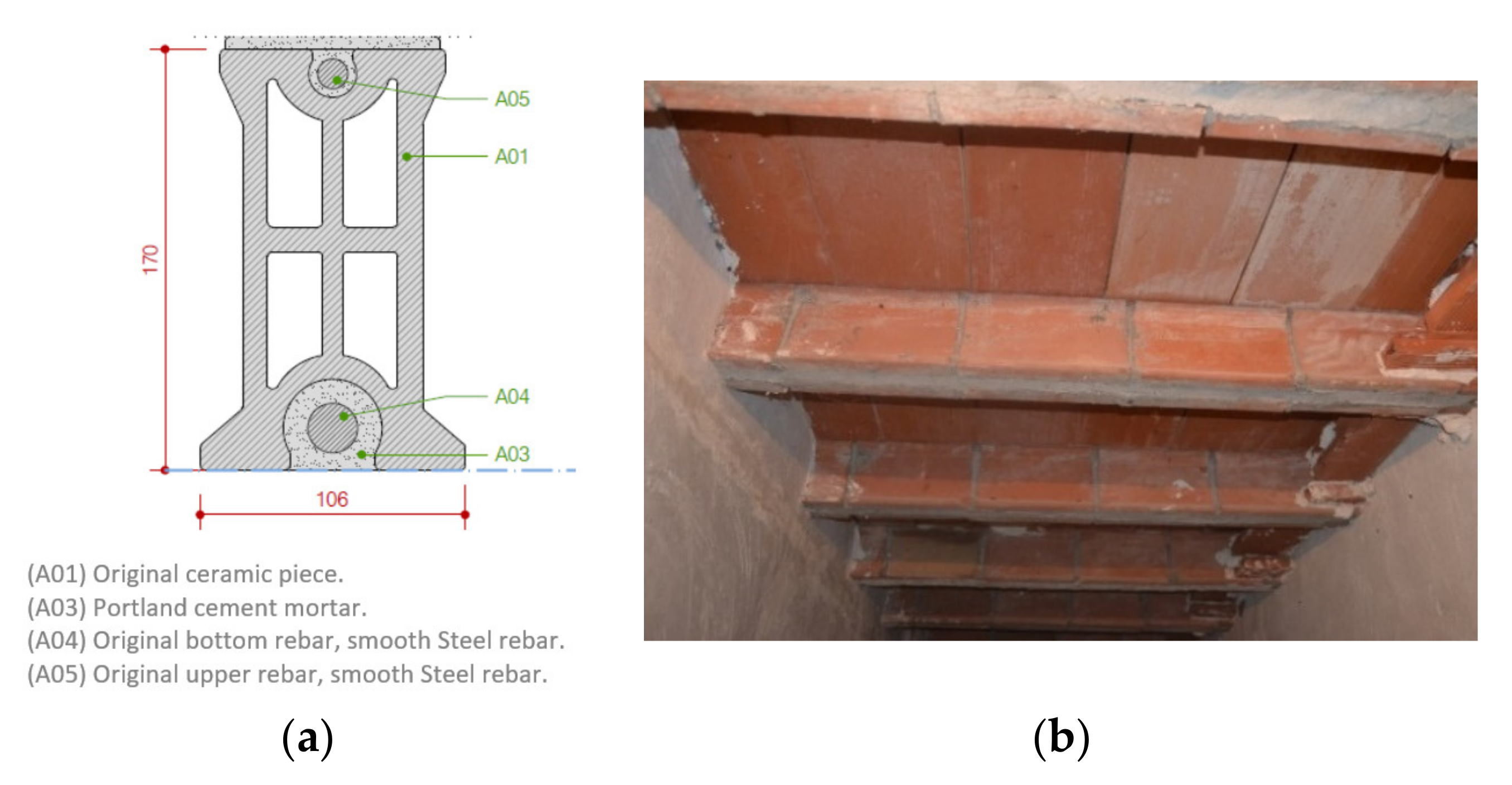
Figure 2.
(a) Location of the building in Alicante on the south-east Mediterranean coast of Spain; (b) Aerial view of the building (denoted by B): (c) General view of the building.
Figure 2.
(a) Location of the building in Alicante on the south-east Mediterranean coast of Spain; (b) Aerial view of the building (denoted by B): (c) General view of the building.


Figure 3.
General view of building’s basement.
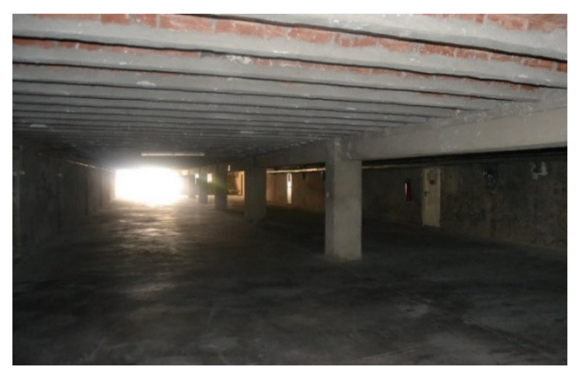
Figure 4.
(a): Central crack on lower surface of a repaired joist. (b): A repaired joist in apparently good condition. (c): Reinforced joist with central crack. (d): Repaired joist with lateral cracks. (e): Repaired joist with badly corroded original reinforcement. (f): View of a corroded steel bar in a previously repaired joist. The exposed part of the rebar had been coated with a blue-grey passivating anti-corrosion product, but the repair was unsuccessful.


Figure 5.
Scheme of flexural strength test ASTM C78 [29].
Figure 5.
Scheme of flexural strength test ASTM C78 [29].

Figure 6.
Lower section of affected part (dimensions in mm): (a) Previous reparation type A; (b) Previous reparation type B; (c) Cut ceramic joist ready for application of the designed prosthesis, after elimination of the affected lower part of the section.
Figure 6.
Lower section of affected part (dimensions in mm): (a) Previous reparation type A; (b) Previous reparation type B; (c) Cut ceramic joist ready for application of the designed prosthesis, after elimination of the affected lower part of the section.
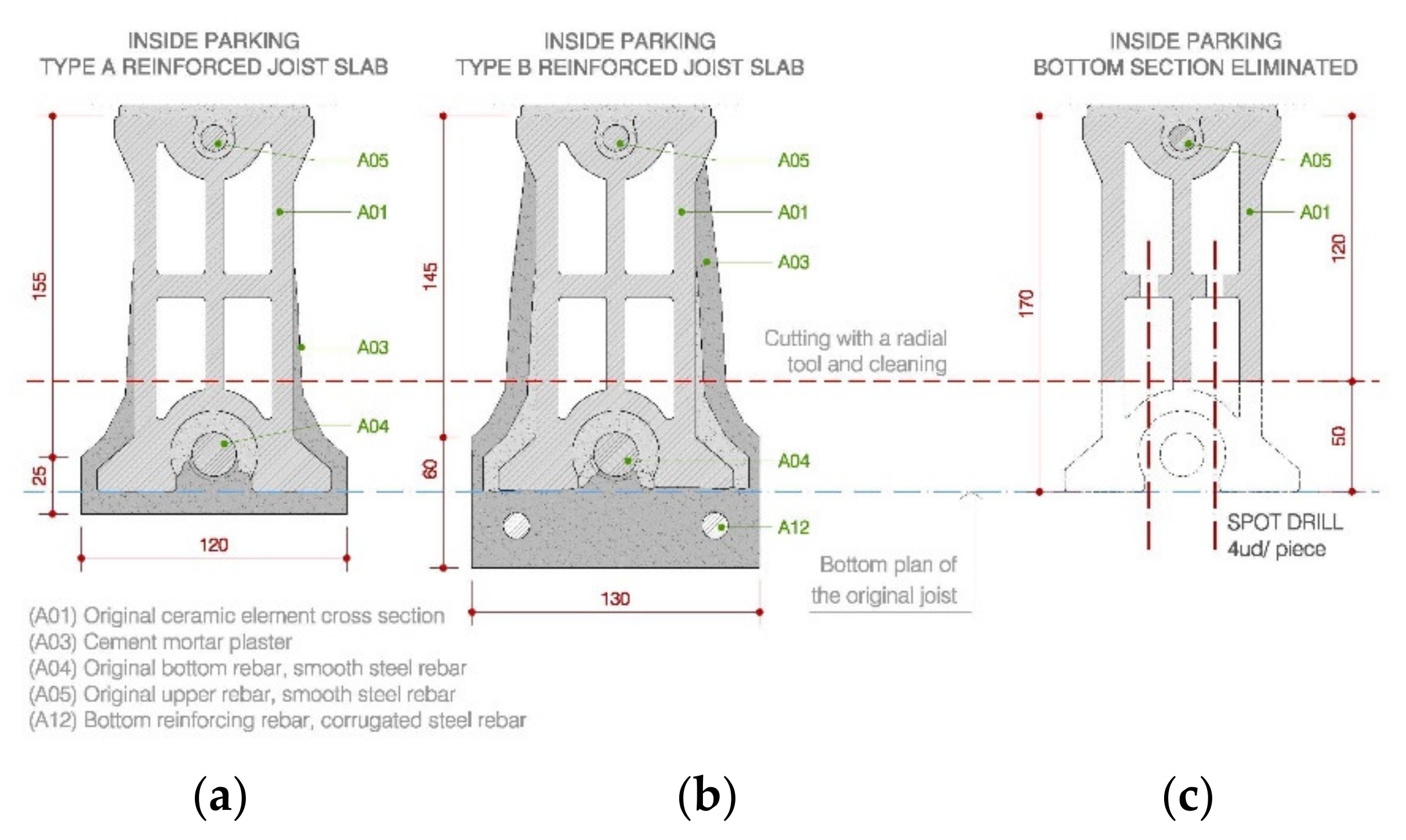
Figure 7.
Vertical scheme of building.
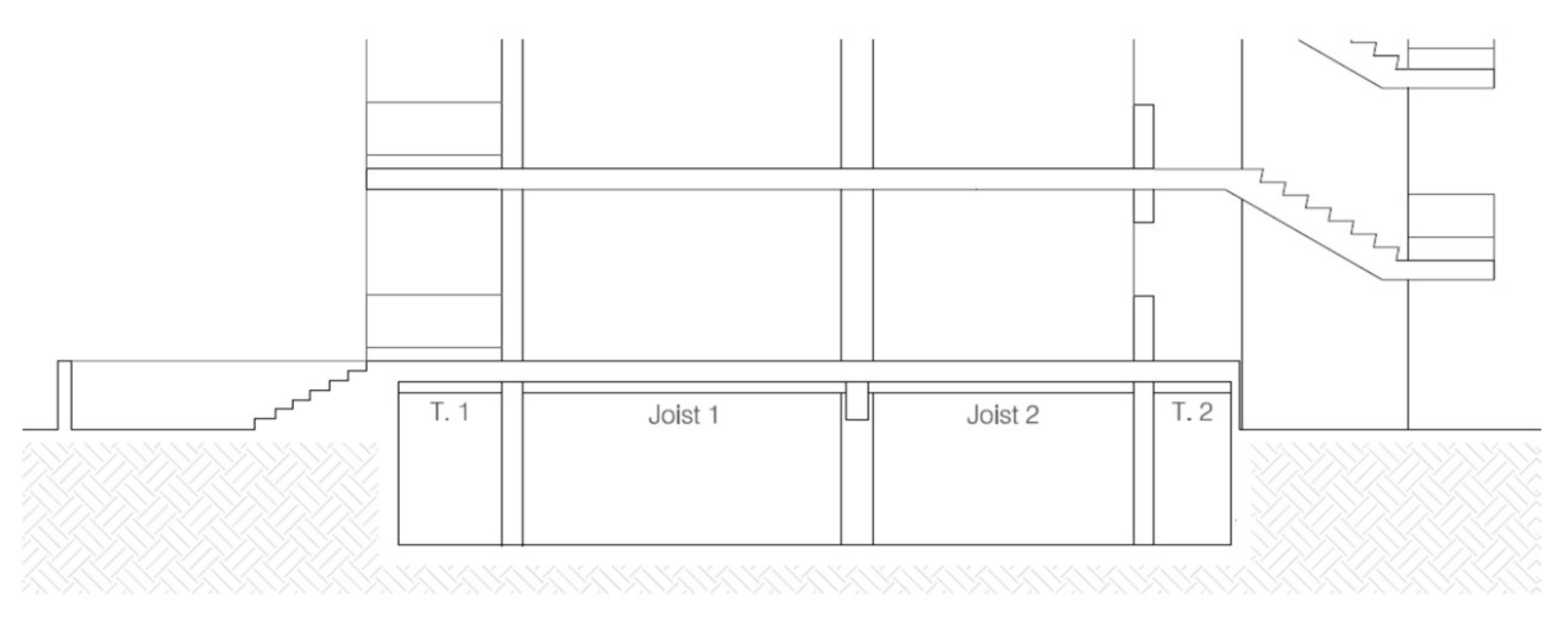
Figure 8.
Scheme of slab structural elements.

Figure 9.
Slab bending moment and shear forces envelopes.
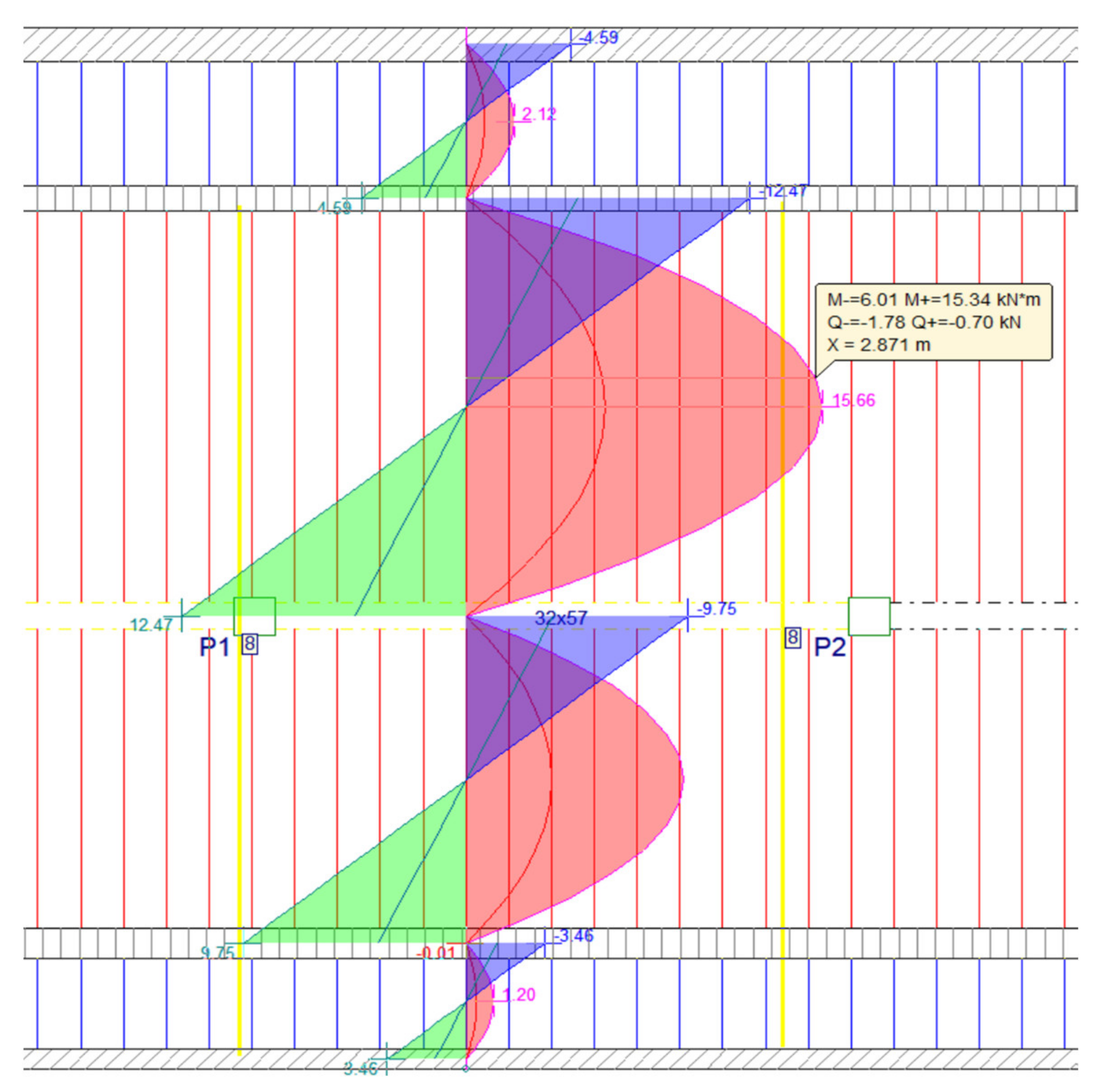
Figure 10.
Proposed stainless steel solution (dimensions in mm).
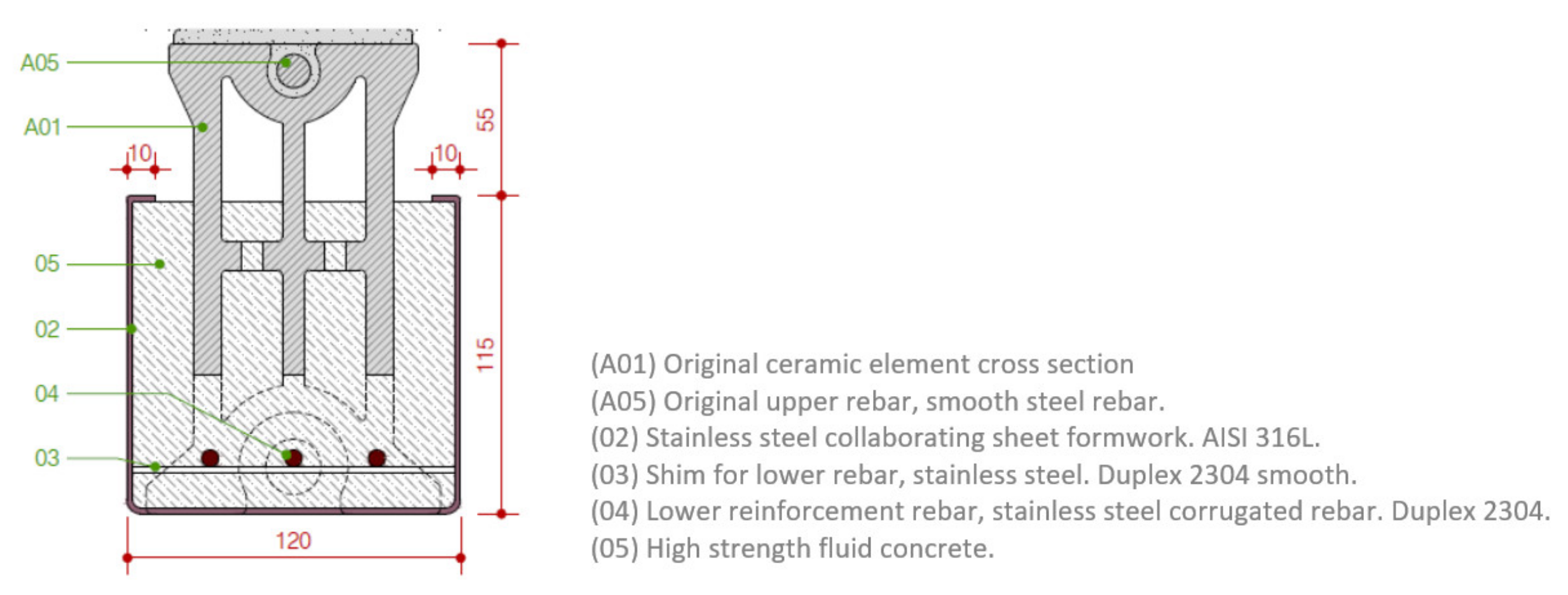
Figure 11.
Verification of 81% efficient reinforced cross section (dimensions in mm).
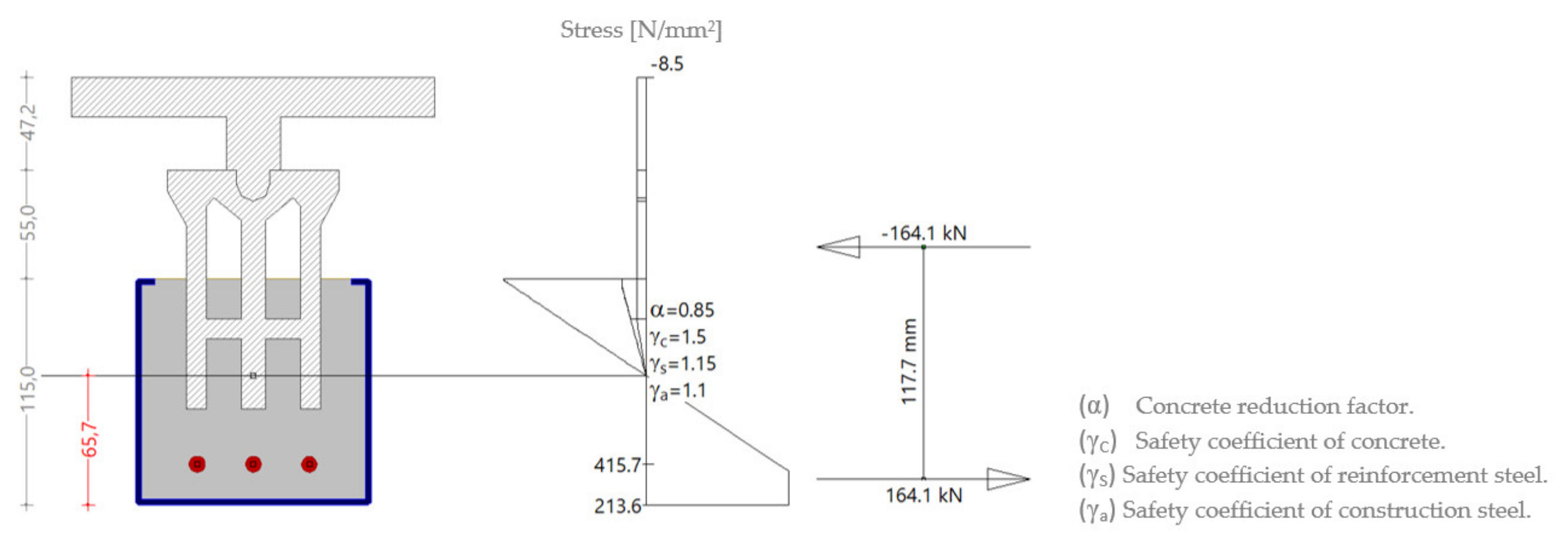
Figure 12.
Finite element stress distribution diagram.
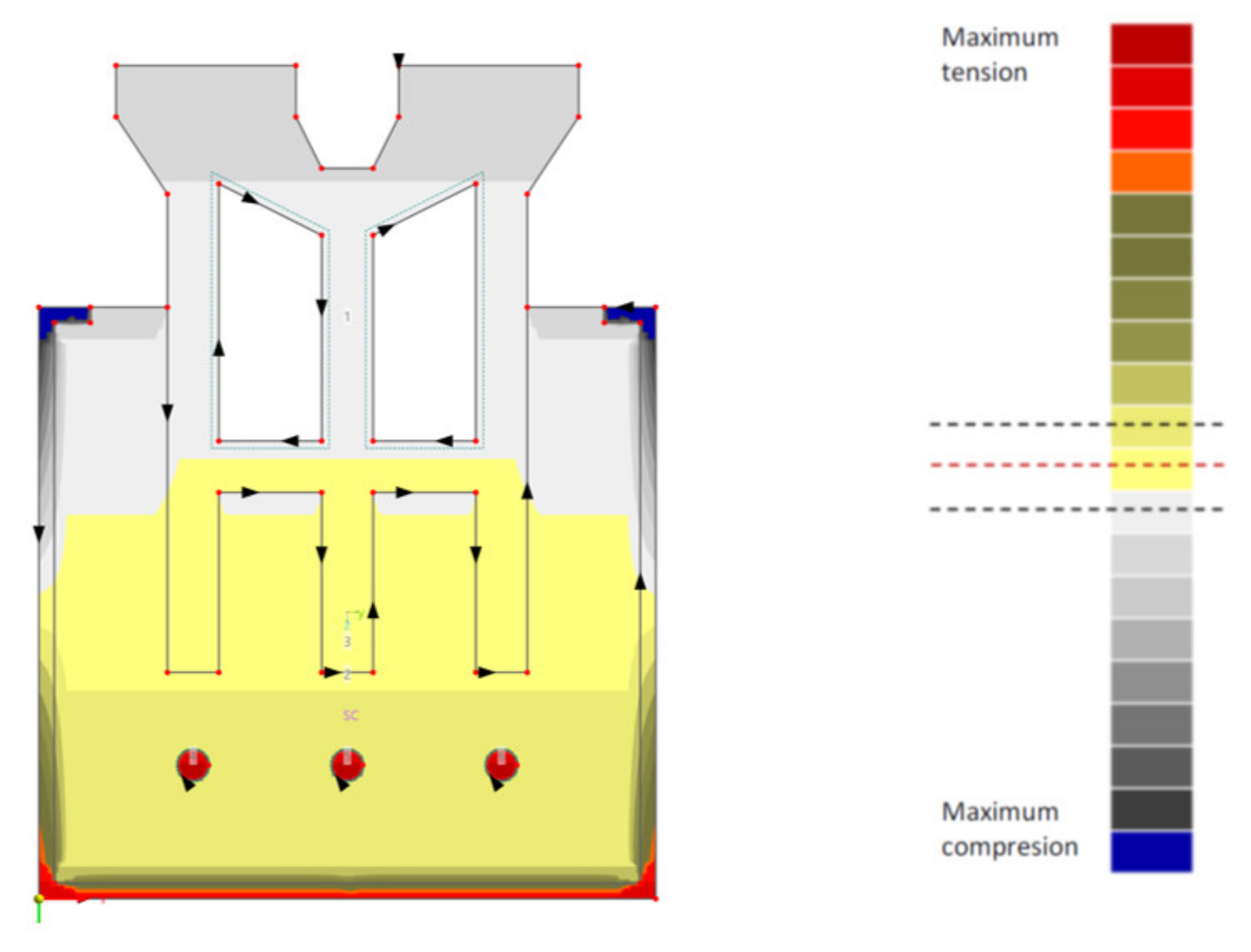
Figure 13.
Verification of strengthened section without metal sheet at 96% efficiency (dimensions in mm).
Figure 13.
Verification of strengthened section without metal sheet at 96% efficiency (dimensions in mm).

Figure 14.
Load capacity curves for different fire exposure times for elements reinforced with carbon and stainless steel 1.4301 and 1.4311 [30].
Figure 14.
Load capacity curves for different fire exposure times for elements reinforced with carbon and stainless steel 1.4301 and 1.4311 [30].

Figure 15.
Prosthesis breakage test set-up.
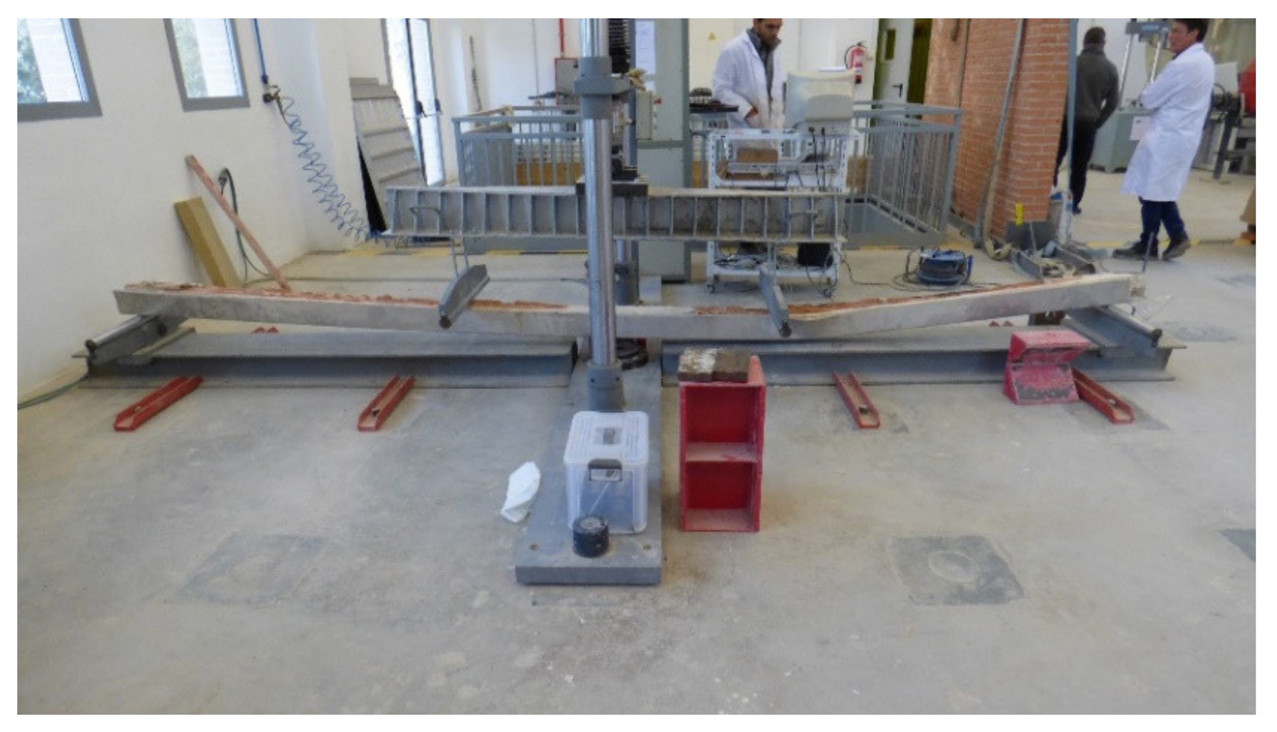
Figure 16.
Stainless steel prosthesis third-point loading test. Applied load (kN) vs. vertical displacement (mm) in the centre of the span.
Figure 16.
Stainless steel prosthesis third-point loading test. Applied load (kN) vs. vertical displacement (mm) in the centre of the span.
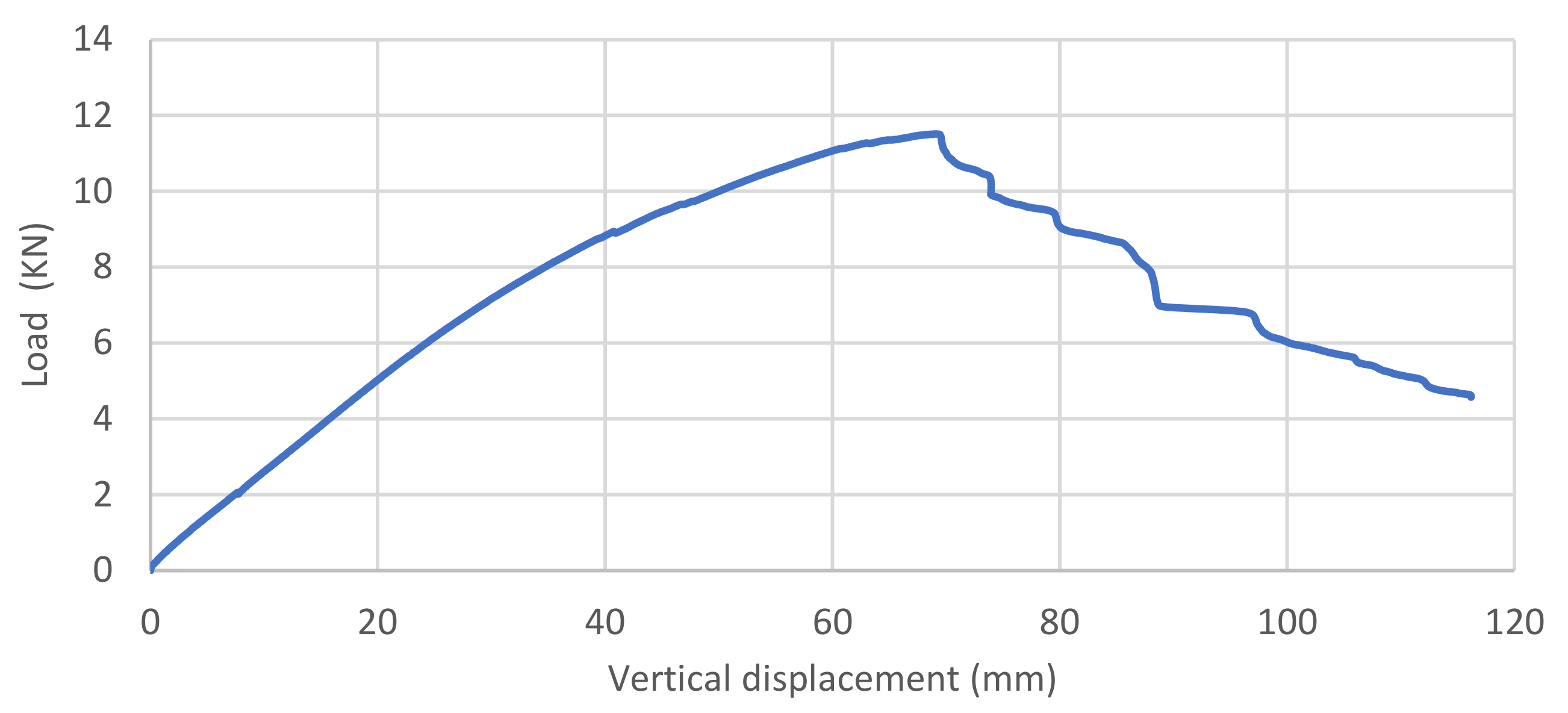
Figure 17.
Test of prosthesis cross section.
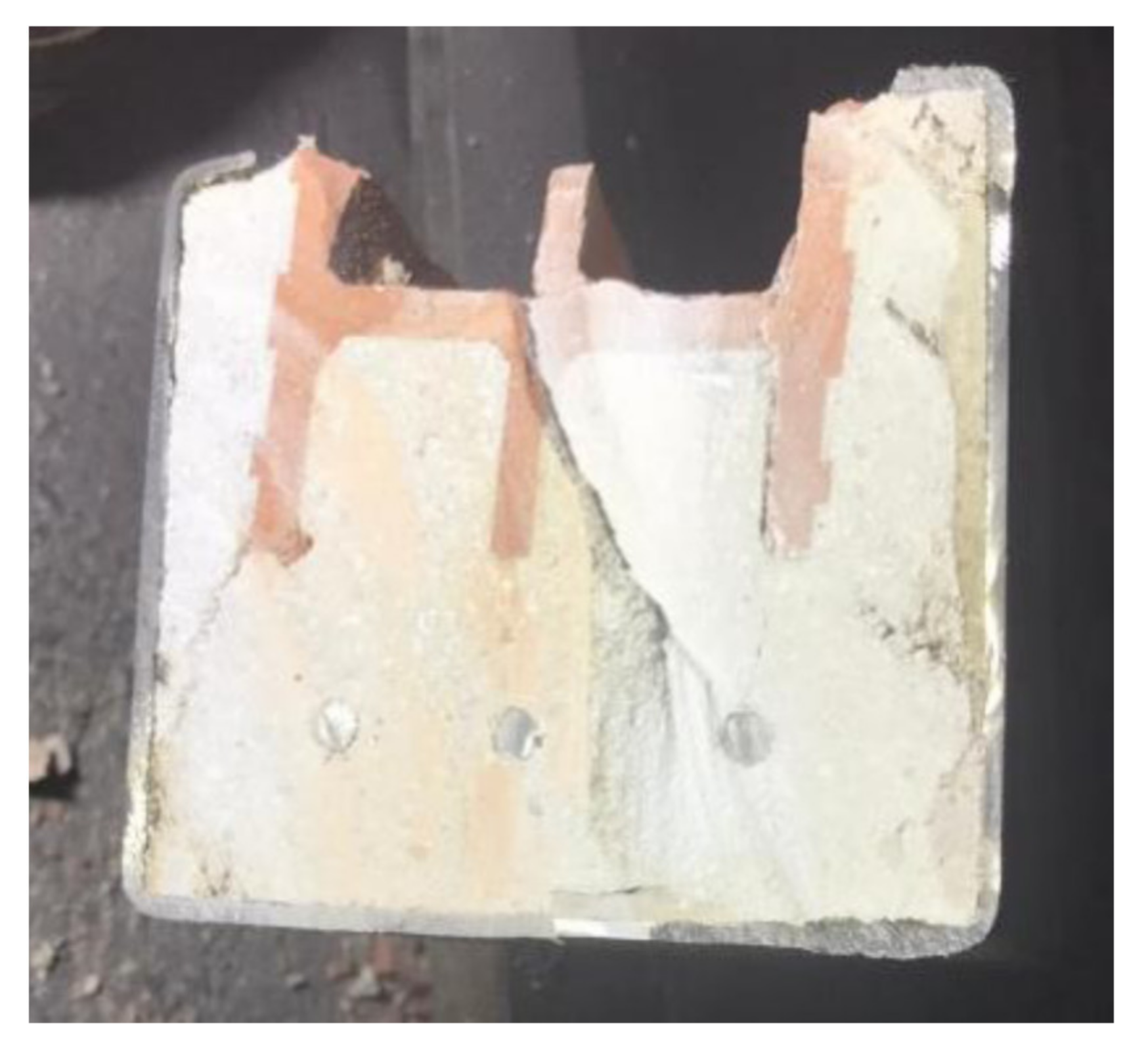
Figure 18.
Specimen for the flexural test. Clay joist violin reinforced with a stainless-steel prosthesis.
Figure 18.
Specimen for the flexural test. Clay joist violin reinforced with a stainless-steel prosthesis.
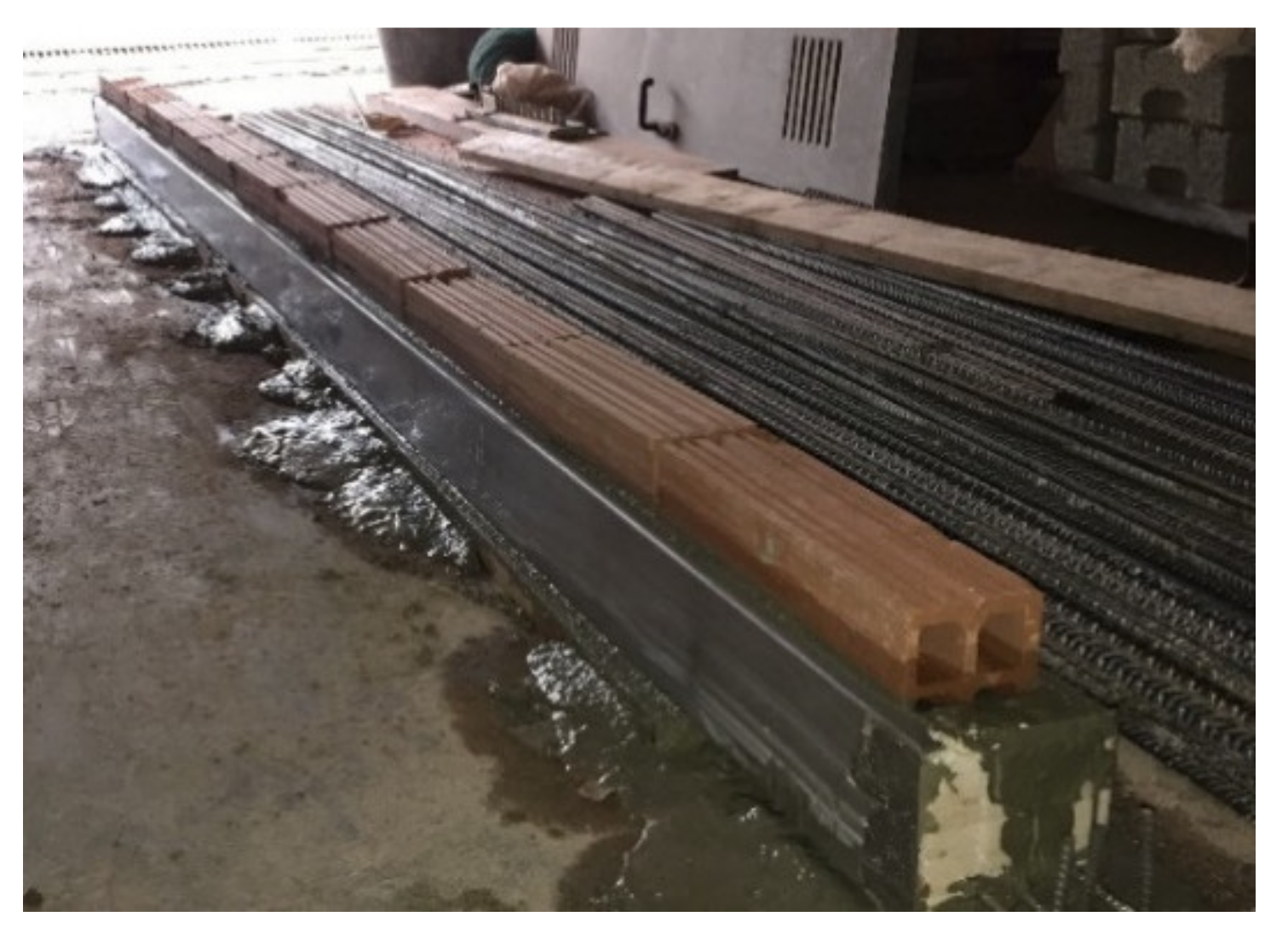
Figure 19.
Flexural tests. Applied load (kN) vs. vertical displacement (mm) in the centre of the span Blue line: Stainless steel prosthesis specimen. Red line: specimen of a clay joist violin reinforced with a stainless-steel prosthesis.
Figure 19.
Flexural tests. Applied load (kN) vs. vertical displacement (mm) in the centre of the span Blue line: Stainless steel prosthesis specimen. Red line: specimen of a clay joist violin reinforced with a stainless-steel prosthesis.
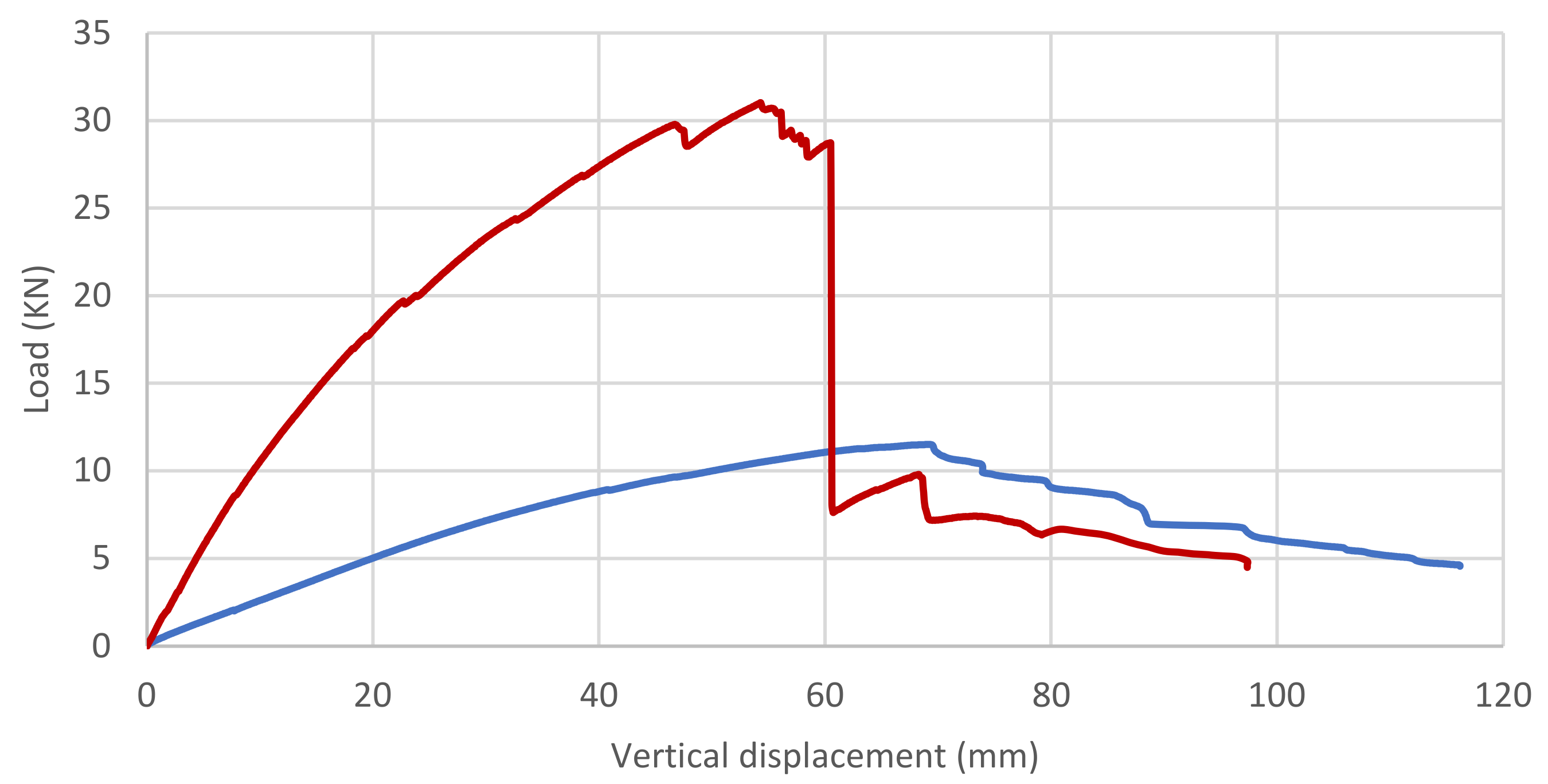
Figure 20.
Structural analysis of isolated resistant section without safety coefficient Mf = 20.80 kN·m (dimensions in mm).
Figure 20.
Structural analysis of isolated resistant section without safety coefficient Mf = 20.80 kN·m (dimensions in mm).

Figure 21.
Final view of the finished repair work.

Figure 22.
Structural analysis of reinforced section without coefficients with 60% efficiency (dimensions in mm).
Figure 22.
Structural analysis of reinforced section without coefficients with 60% efficiency (dimensions in mm).


Table 1.
Chemical compositions (% by mass) of the two stainless steels used in this work.
| Designation | C | Cr | Ni | Mo | N | Si | Mn | S | P | PREN Index * |
|---|---|---|---|---|---|---|---|---|---|---|
| AISI 316 L | ≤0.03 | 16.00–18.00 | 10.00–12.00 | 2.00–2.50 | ≤0.75 | ≤2.00 | ≤0.03 | ≤0.04 | 24.1 | |
| Duplex 2304 | ≤0.03 | 22.00–24.00 | 3.50–5.50 | 0.10–0.60 | 0.05–0.20 | ≤1.00 | ≤2.00 | ≤0.015 | ≤0.035 | 25.6 |
(*) PREN index values provided by the manufacturer.
Table 2.
Mechanical properties of the two stainless steels used in this work.
| Designation | Yield Strength Rp0.2 (N/mm2) | Tensile Strength Rm (N/mm2) | Elongation A5 (%) |
|---|---|---|---|
| AISI 316 L | >240 | 540–620 | >45 |
| Duplex 2304 | ≥450 | 650–850 | ≥25 |
Publisher’s Note: MDPI stays neutral with regard to jurisdictional claims in published maps and institutional affiliations. |
© 2022 by the authors. Licensee MDPI, Basel, Switzerland. This article is an open access article distributed under the terms and conditions of the Creative Commons Attribution (CC BY) license (https://creativecommons.org/licenses/by/4.0/).
Share and Cite
MDPI and ACS Style
Salmerón, A.; Climent, M.-Á.; Ivorra, S. Violin Ceramic Joist Slabs: Evaluation and Proposal for Intervention with Duplex-Type Stainless Steel. Buildings 2022, 12, 942. https://doi.org/10.3390/buildings12070942
AMA Style
Salmerón A, Climent M-Á, Ivorra S. Violin Ceramic Joist Slabs: Evaluation and Proposal for Intervention with Duplex-Type Stainless Steel. Buildings. 2022; 12(7):942. https://doi.org/10.3390/buildings12070942
Chicago/Turabian StyleSalmerón, Antonio, Miguel-Ángel Climent, and Salvador Ivorra. 2022. "Violin Ceramic Joist Slabs: Evaluation and Proposal for Intervention with Duplex-Type Stainless Steel" Buildings 12, no. 7: 942. https://doi.org/10.3390/buildings12070942
Note that from the first issue of 2016, this journal uses article numbers instead of page numbers. See further details here.