
On the Applicability of Conventional Seismic Design Methodologies to Hybrid RC-Steel Systems


1
CONSTRUCT-LESE, School of Engineering, Polytechnic of Porto, 4249-015 Porto, Portugal
2
CONSTRUCT-LESE, Faculty of Engineering, University of Porto, 4200-465 Porto, Portugal
*
Author to whom correspondence should be addressed.
Buildings 2022, 12(10), 1558; https://doi.org/10.3390/buildings12101558
Submission received: 13 August 2022
/
Revised: 5 September 2022
/
Accepted: 23 September 2022
/
Published: 28 September 2022
(This article belongs to the Collection Seismic Safety Assessment and Strengthening of Existing Constructions)
Abstract
:This paper addresses the application of conventional (force-based) seismic design methodologies to hybrid RC-steel systems. The q-factor-based EC8-3 seismic assessment procedure is first reviewed. A case-study application follows, analyzing and discussing the difficulties a practitioner will face when assessing the efficiency of a steel-brace retrofitting system designed within the framework of EC8-1. Afterward, the performance of the obtained retrofitted structure is evaluated using nonlinear analysis. The obtained results are discussed in light of the EC8-3 performance requirements, and conclusions are drawn about the adequacy of the force-based design (FBD) methodology (and associated q-factors) for such situations. The study shows that the process does not ensure the adequate seismic behavior of the retrofitted structures. It thus calls for the development of an effective performance-based design methodology that explicitly considers the interaction between the two structural systems (RC structure and steel braces), namely the influence of the steel braces’ resistance on the deformation capacity of RC members.
1. Introduction
Seismic design is currently codified by structural codes and standards of practice using force-based design (FBD). This is mainly due to historical reasons and related to how design is carried out for other actions (such as dead and live loads) [1]. The procedure involves the consideration of a behavior factor (q-factor) as a simple mean to account for structural nonlinearity while performing linear static analysis. However, in non-seismically designed RC structures, the uncertainties associated with the nonlinear behavior are relevant (e.g., the location and ductility capacity of the potentially inelastic regions are not fully known), making it therefore very difficult to define a direct correlation between the real internal forces that develop in structural members during the seismic excitation, and those experienced by an equivalent indefinitely elastic structure. Consequently, several authors (e.g., [2]) have argued that the force-based seismic assessment and retrofitting of existing RC buildings will not yield, in general, satisfactory results.
With the purpose of providing information about the seismic performance of RC buildings strengthened with steel braces, several experimental and analytical studies have been conducted over the last years. Only a few (e.g., [3,4]) have resulted in proposals for q-factors to be applied in the design process and, moreover, limited confidence arises due to the discrepancy between results. In fact, the latter have shown that the improvement in the seismic behavior is not proportional to the corresponding increase in lateral strength, which suggests that a q-factor-based design process might not lead to solutions with acceptable seismic performance. As such, the nonlinear behavior of the existing and retrofitted structures should be explicitly accounted for, despite some increase in complexity of the assessment and design procedures. However, due to the simplicity and popularity of the q-factor approach for the design of new structures, practitioners dealing with the seismic assessment and strengthening of existing RC buildings are more likely to resort to it than to the more complex nonlinear static and dynamic procedures. The potential consequences of this option are therefore examined in the following sections.
2. The q-Factor Approach in EC8-3
Clause 4.1(3) of EC8-3 [5] states that the assessment procedure should be carried out by means of the general analysis methods specified in Section 4.3 of EC8-1 [6], as modified per the former standard to suit the specific problems encountered in the assessment. For a chosen performance requirement, the effects of the seismic action (combined with the other permanent and variable loads) can thus be evaluated by means of linear or nonlinear methods of analysis, depending on the characteristics of the structure under evaluation and the choice of the analyst. Each of these methods involves different levels of complexity, accuracy, and computational effort, as well as of requirement for specialized knowledge in the field. The q-factor approach—a linear static design method based on the reduction of the seismic force demands—is prescribed by EC8-1 as the basic design method and usually referred to as the most conservative [7].
The seismic action to be adopted when using the q-factor approach within the context of EC8-3 is referred in its clauses 2.2.1(4) and 4.2(3). The design spectra for linear analysis are the ones defined in section 3.2.2.5 of EC8-1, scaled to the values of the design ground acceleration established for the verification of the different limit states (LS). A default value of q = 1.5 is proposed for RC structures, regardless of the structural type. Higher values may eventually be adopted if suitably justified with reference to the local and global available ductility (evaluated according to the relevant provisions of EC8-1), but this is usually not easy to do. Clause 2.2.2(3) of EC8-3 does, however, indicate that the value of q = 1.5 (or a duly justified higher one) corresponds to the fulfilment of the LS of Significant Damage (SD). If the LS under evaluation is that of Near Collapse (NC), that value may be increased by approximately one-third, although it is also indicated that this approach is generally not suitable for checking that LS.
Regarding structural modelling, clause 4.3(2) of EC8-3 states that the provisions of sections 4.3.1 and 4.3.2 in EC8-1 should be applied without modifications. In particular, member stiffness should be simulated according to paragraphs 4.3.1(6) and 4.3.1(7). The former states that the effect of cracking should be considered by evaluating stiffness at the time when the reinforcement starts to yield. The latter states that, unless a more accurate analysis of the cracked elements is performed, their flexural and shear stiffness properties may be taken equal to one-half of those of the uncracked elements. This simplified 50% stiffness reduction is widely used and generally accepted for the design of new structures, but it is difficult to justify for the assessment of existing structures, especially when applied to members that are prone to early cracking [7]. However, within the straightforward context of developing a linear elastic analysis model to be used with the q-factor design approach, this simplification is deemed acceptable.
Concerning safety verifications, clauses 2.2.1(4) to (7) of EC8-3 state that all structural elements should be verified by checking that seismic demands do not exceed the corresponding capacities in terms of strength. For the application of the latter to ductile or brittle elements, mean value properties of the existing materials should be used as directly obtained from in situ tests and additional sources of information, appropriately divided by the applicable confidence factors. For new or added materials, nominal properties should be adopted. In the case of brittle elements, material strengths should be further divided by the partial factor of each material when calculating the corresponding strength capacities. For the verification of the limit states of NC and SD, clauses 2.2.2(3) and 2.2.3(3) establish that demands shall be based on the reduced seismic demand relevant for each LS, and capacities evaluated as for non-seismic design situations. On the other hand, for the LS of Damage Limitation (DL), clause 2.2.4(3) indicates that demands and capacities shall be compared in terms of mean inter-story drift. Two shortcomings can thus be pointed out to the EC8-3 safety verification procedure when using the q-factor design approach: (i) RC member capacities are the same for the limit states of NC and SD (given the installed axial force), and (ii) no limit values are recommended for the inter-story drifts to be observed when checking for the LS of DL.
The above-referred criteria are summarized in Table 4.3 in EC8-3, including the values of the material properties to be adopted when evaluating the demands and capacities of ductile and brittle elements, for all types of analysis, as well as the criteria that shall be followed for the corresponding safety verifications. However, inconsistencies seem to exist between the contents of Table 4.3 regarding the q-factor approach and what is stated in the precedent text: (i) it is said that demands on brittle elements should be determined in accordance with the relevant section of EC8-1, which appears to be a reference to the capacity design rule (Section 5.2.3.3) and related others (no reference to this procedure exists in the text concerning the q-factor approach); (ii) it is said that the mean values of material properties should be divided by both the confidence factor and the material partial factor when calculating the capacities of elements (the precedent text only applies the material partial factor to the case of the capacities of brittle elements).
3. Application to a Retrofitting Case-Study
Section 5.1.2 in EC8-3 states that the selection of the “type, technique, extent, and urgency” of the retrofitting intervention should be based on the structural information collected during the assessment of the building. The following aspects should be taken into account: (i) all identified local gross errors should be appropriately remedied; (ii) structural regularity should be improved as much as possible, both in elevation and in plan; (iii) increase in the local ductility supply should be provided where required; (iv) the increase in strength after the intervention should not reduce the available global ductility. The required characteristics of regularity and resistance can be achieved by either the modification of the strength and/or stiffness of an appropriate number of existing components (local modification), or by the introduction of new structural elements (global modification). The procedure to design the retrofitting system should include the following steps: (a) conceptual design; (b) analysis; (c) verifications. The conceptual design stage should cover the following: (i) selection of techniques and/or materials, as well as of the type and configuration of the intervention; (ii) preliminary estimate of dimensions of additional structural parts; (iii) preliminary estimate of the modified stiffness of the retrofitted elements. Structural analysis should then be performed considering the modified characteristics of the building, and safety verifications should be carried out for existing, modified, and new structural elements. Finally, the description of the expected effect of the retrofitting solution on the structural response of the building should be included in the design documentation. The following sub-sections go through these steps following the approach described in the previous section to the case-study structure.
3.1. Structural Characterization
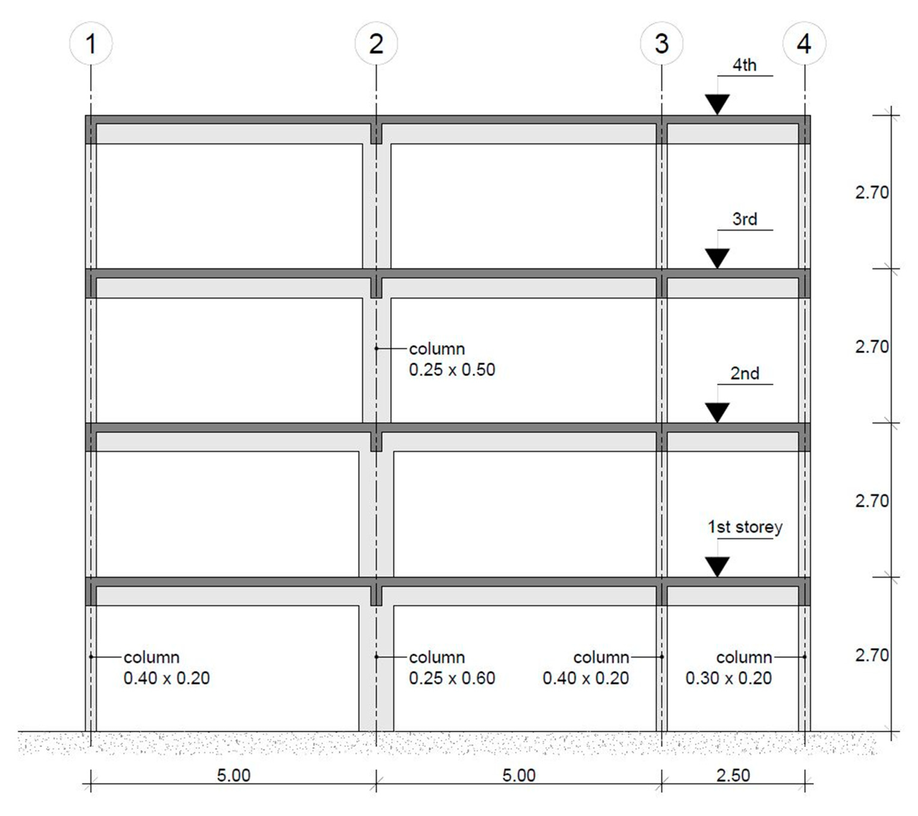
The chosen RC structure is representative of the design and construction common practice in southern European countries—such as Italy, Portugal, and Greece—until the late 1970s. As such, it was designed to withstand vertical loads only. The reinforcement details were specified according to the available codes and construction practice at that time. Hence, no specific seismic detailing was considered, no preferential inelastic dissipation mechanisms were assumed, and no specific ductility or strength provisions were considered [8]. Figure 1 shows an elevation view of the structure: a four-story frame with three bays (two spans of 5.0 and one of 2.5 ). The inter-story height is 2.7 . Equal beams (geometry and reinforcement) exist on all floors, with cross-section dimensions of (width) 250 × (height) 500 . Concerning the columns, all but the wider interior one (Column 2) have equal geometric characteristics along the height of the structure. Because Column 2 mobilizes its stronger flexural inertia axis, it plays a dominant role in the frame’s seismic response. As such, it will be referred to as “strong column” henceforth. The cross-section dimensions of the latter are (width) 250 × (height) 600 on the first and second stories, and (width) 250 × (height) 500 on the third and fourth stories; those of Columns 1 and 3 are (width) 400 × (height) 200 ; and those of Column 4 are (width) 300 × (height) 200 . The reinforcement details of columns and beams are shown, respectively, in Figure 2 and Figure 3.
Further details about the structure, its material properties, and vertical loading can be found in [9], as well as the seismic assessment. The latter was performed according to the provisions of EC8-3, considering a moderate-high European seismic hazard scenario, and running nonlinear static and dynamic analyses. The results for the LS of NC show that deformation tends to concentrate on the third story, leading to the formation of a soft-story mechanism. They also show that the strong column is the most likely to suffer damage due to excessive shear force, as it absorbs most of the total story shear (typically, more than 70%). Moreover, the chord rotation and shear force ratios on other members are also quite high. This indicates that the structure will benefit the most from a global retrofitting solution capable of reducing floor displacements, eliminating the irregular response of the third story, and reducing the shear demand on columns. A strengthening intervention with concentric X-diagonal steel braces is therefore proposed herein. Figure 4 shows the layout of the bracing system. The diagonals are composed of hot-rolled circular hollow section (CHSH) steel profiles, directly connected to the RC beam–column nodes of the central bay. The connection is considered to behave as a “nominally pinned joint” (as defined in EC3-1-8 [10]), i.e., capable of transmitting the internal forces without developing significant moments. At the points where the braces cross, no structural connections exist.
3.2. Design of the Retrofitting System
As no specific rules for the design of hybrid RC-steel systems exist in EC8-1, its provisions concerning steel frames with concentric braces were taken as reference and starting point for the design of the retrofitting system. Beginning with the braces’ layout, clause 6.7.1(2) requires diagonal elements to be placed in such a way that the structure, under load reversals, exhibits similar load deflection characteristics at each story, in opposite senses of the same braced direction. To that end, the rule provided by clause 6.7.1(3) should be met on every story. The geometry shown in Figure 4 meets this requirement, so no changes were necessary. A linear elastic analysis model was then developed according to the requirements of Section 4.3.1 of EC8-1, and the frame was analyzed under the effect of vertical loads combined with the seismic demand defined by the NC acceleration elastic response spectrum. The effect of the compressed braces was neglected during the analysis, as required by clause 6.7.2(2), and behavior factors q corresponding to two different ductility classes (DCL: q = 1.5; DCM: q = 3.0) were considered to obtain the seismic forces on the retrofitted structure.
Concerning the detailed design of the steel braces, the applicable provisions of Section 6.7.3 of EC8-1 were taken as reference: (i) The non-dimensional slenderness , as defined in EC3-1-1 [11], should be limited to ; (ii) the yield resistance of the gross section should be such that , where is the design axial force demand on the tensioned brace; (iii) the maximum overstrength ratio over all braces should not differ more than 25% from the minimum value . The lower limit to the non-dimensional slenderness is adopted so that, during the pre-buckling stage (when both compression and tension braces are active), the RC frame’s columns are not overloaded beyond the action effects obtained from the analysis at the ultimate stage (when only the tension braces are taken as active). Regarding the imposition of a maximum difference of 25% between the overstrength ratios , it aims to ensure a homogeneous dissipative behavior of the steel braces. The definition of a retrofitting solution that fulfilled these conditions required an iterative analysis and design procedure that was carried out considering the two previously referred q-factors. Table 1, Table 2 and Table 3 summarize the obtained results, considering a design yield stress equivalent to that of steel grade S275 (EC3-1-1).
The design axial forces on the tensioned braces, as well as the fundamental period and base shear values shown above, were obtained considering the effective (secant-to-yield) stiffness of RC elements equal to one-half of their gross stiffness . As referred in Section 2, this is the default procedure according to clause 4.3.1(7) of EC8-1 to consider the effect of cracking when performing seismic design using linear elastic analysis models. Concerning the shaded values of and , those indicate situations for which the design provisions of Section 6.7.3 were not fulfilled. However, the maximum value of the non-dimensional slenderness is only slightly exceeded, and it is well known that the condition regarding the maximum difference between overstrength ratios is often hard to fulfil on top stories [12,13]. Moreover, it is recalled that these are design provisions that apply to concentric-braced steel frames, therefore not being mandatory for the design of steel-braced RC structures.
3.3. RC Member Safety Checks
For the retrofitting system to be deemed adequate, the RC members must be proven safe by checking that seismic demands do not exceed their (ductile and brittle) capacities in terms of strength, while duly considering the axial forces induced by the steel braces. As referred in Section 2, clauses 2.2.2(3) and 2.2.3(3) of EC8-3 state that capacities shall be evaluated as for non-seismic design situations. However, to allow for the possibility that the actual yield strength of the steel braces is higher than their nominal yield strength , the safety checks were performed herein according to the capacity design rule specified in Section 6.7.4 of EC8-1, adapted to RC members, and reproduced below in Equation (1):
where is the design axial resistance of the beam or column according to EC2-1-1 [14], considering the interaction of the axial resistance with the bending moment , the latter being defined by its value in the seismic design situation; is the axial force in the beam or column due to the non-seismic actions included in the combination for the seismic design situation; is the axial force in the beam or column due to the design seismic action; is the overstrength factor as defined in clause 6.1.3(2) of EC8-1; is the minimum overstrength ratio over all steel braces, as defined above. Additionally, the shear force demands in the seismic design situation were checked against the shear force capacity values obtained with the provisions of EC2-1-1.
The results of the safety checks are shown in Figure 5 and Figure 6, in terms of demand-to-capacity ratios () for each control section , using a graphical representation to provide a better view of the outcome provided by each retrofitting system. For comparison purposes, the ratios referring to the seismic assessment of the BF according to the q-factor approach are also included. Figure 5 and Figure 6 thus show, respectively, the NC flexural and NC shear force ratios on the columns of the bare (BF) and retrofitted (DCL; DCM) frames. As for the beams, the ratios were found to be consistently below 1.0, therefore the corresponding graphical representation is deliberately omitted.
The ratios comparison shows the drastic improvement in the seismic behavior of the frame resulting from the inclusion of the steel braces. Even though some control sections remained unsafe when considering the DCL retrofitting system, the global assessment scenario is completely different from that of the BF, which revealed generalized excessive flexural demands and clearly excessive shear demands imposed on column C2 on the first, second, and third stories. The fact that the flexural ratios for column C3 on the first story are higher in the DCL than they were in the BF indicates that the global axial force induced by the tensioned steel braces is higher than that column can resist. Therefore, the DCL retrofitting system, for being too robust, should be deemed inadequate. On the other hand, when considering the DCM retrofitting system, both the flexural and shear force ratios were found to be below 1.0 on all control sections, thus allowing the DCM frame to be deemed safe for the LS of NC according to the q-factor approach.
4. Evaluation of the Designed Retrofitting System
Due to the several adjustments that were introduced in the previous section to the provisions of EC8-1, to try to adapt them to the design of hybrid RC-steel systems, the performance of the allegedly safe retrofitted frame (DCM) will now be evaluated using nonlinear static and dynamic analyses. The results will then be discussed in light of the applicable EC8-3 performance requirements for the LS of NC, and conclusions will be drawn about the effective seismic safety of the structure.
4.1. Numerical Modelling
The nonlinear analysis models of the bare (BF) and retrofitted (DCM) frames were developed using the software platform SeismoStruct [15]. Figure 7 illustrates the general characteristics of the DCM model, which is obtained from that of the BF simply by adding the necessary elements to simulate the inclusion of the steel braces. A distributed plasticity model was considered for the RC frame members, combined with fiber discretization to represent cross-section behavior (approximately 200 fibers per section). A force-based FE formulation was used (one FE per member), considering five integration sections per element according to the recommendations of Calabrese et al. [16]. As for the constitutive laws defining the cyclic behavior of the concrete and steel rebar material, the Mander et al. model [17] and the Menegotto and Pinto model [18] combined with the isotropic hardening rules proposed by Filippou et al. [19] were, respectively, employed with the following mechanical properties (mean values): concrete compressive strength ; concrete tensile strength ; concrete modulus of elasticity (initial elastic stiffness) ; concrete strain at unconfined peak compressive stress ; concrete specific weight ; steel yield stress ; steel modulus of elasticity (initial elastic stiffness) ; steel strain hardening parameter ; steel specific weight . Further details concerning the modelling of the BF can be found in [9].
The modelling options for the steel braces were based on the studies carried out by Elghazouli [20], D’Aniello et al. [21], Karamanci, and Lignos [22]. A distributed plasticity model was also considered for these members, with similar characteristics to those described above. The connections to the RC frame were modelled using the link elements (“zero-length” elements) available in SeismoStruct. This required the definition of nodes at the ends of the steel braces, with the same coordinates as those of the nodes on the RC frame to which the braces connect. The “nominally pinned joint” behavior referred to above was obtained by editing the stiffness factor of the corresponding moment-rotation law of the link elements placed between the end nodes of the steel braces and the connecting nodes on the RC frame (centerline modelling was assumed for beam–column joints, along with concentric braces). Concerning the constitutive law defining the cyclic behavior of the braces’ steel material, the Menegotto and Pinto model [18] was employed, combined with the isotropic hardening rules proposed by Filippou et al. [19], with the following mechanical properties (mean values): modulus of elasticity (initial elastic stiffness) ; mean yield stress ; strain hardening parameter ; specific weight .
While the above-referred modelling aspects are consensual among authors, others are not, such as the number of FEs per individual brace, or the brace’s initial camber . It is, however, widely accepted that the brace should be divided at least in two FEs that are offset (initial camber) at the member’s mid-length, as to trigger flexural buckling (see Figure 8). Hence, in order to be able to reproduce the buckling response of the braces as close as possible to their expected behavior, a parametric study was conducted using a single brace auxiliary model. The single brace was modelled with the same length ( = 5.68 m) and support conditions (nominally pinned) as the braces of the retrofitted structure. Three different cross-sections were considered to obtain values of relative slenderness between 1.5 and 2.5, while the effect of the FE mesh size was considered by varying the number of elements between 2 and 8. Regarding the effect of the initial camber, a bilinear shape was considered with amplitude varying in the range of 0.1% to 0.4% of the brace’s total length . All other modelling options were set as described above. The models were then analyzed under monotonically increasing axial displacements, and the response curves—in terms of axial force–axial displacement and axial force–lateral displacement—were plotted against the values of the design buckling loads calculated according to EC3-1-1. The obtained response curves can be found in [9].
The results provided by the above-referred study indicated that the size of the FE mesh has significant influence on the numerical response of the compressed braces. Using only two FEs, the buckling loads were often higher than the corresponding Euler’s critical load, unless for the cases in which the considered camber’s amplitude was relatively high (between L/500 and L/250). Moreover, the value of the camber amplitude required to obtain a buckling load close to that given by the provisions of EC3-1-1 increased with the slenderness of the brace, which did not seem reasonable. Therefore, the discretization with two finite elements was deemed unsatisfactory as a modelling option. On the other hand, the buckling loads obtained with discretization with eight finite elements were always below the corresponding Euler’s critical load, regardless of the considered camber amplitude. Moreover, the values obtained with camber amplitudes between L/1000 and L/500 were not significantly different within each tested slenderness and showed good agreement with the design buckling loads provided by EC3-1-1. Therefore, the discretization using eight finite elements and the adoption of an initial camber equal to L/750 at mid-length were deemed as adequate modelling options to numerically reproduce the buckling response of steel braces as close as possible to their expected behavior. All the results given in the following sub-sections were thus obtained based on these and on all the other above-referred nonlinear modelling options for RC members and steel braces.
4.2. Seismic Demand Definition
The base seismic demand for the EC8-3 assessment process was set by the NC elastic response acceleration spectrum corresponding to a moderate-to-high European seismic hazard scenario defined in [9], as referred above. The target displacements for the nonlinear static analyses were then determined through the nonlinear static procedure (NSP) recommended in EC8-1 (i.e., the N2 method [23]). Because the structure is not symmetric about any axis at right angles to the seismic action’s direction, the analysis had to be carried out for both senses of the latter (left-to-right and right-to-left). Table 4 shows the obtained results for the DCM, along with those for the BF (for comparison).
The ground motion records employed in the nonlinear dynamic analyses were selected using the SelEQ engine [24]. Seven records were obtained from real earthquake events and scaled to meet the spectral matching requirements defined in EC8-1, as well as the recommendations of Araújo et al. [25]. The seismological criteria for the preliminary search that was first carried out by SelEQ were based on the characteristics of the events that define zone 1.3 of the Portuguese territory, according to the country’s National Annex (NA) in EC8-1. Magnitudes and epicentral distances higher than 5.5 and 20 km, respectively, were considered accordingly. Additionally, an interval of values between 360 m/s and 800 m/s was considered for the average shear wave velocity , in agreement with the type B ground as defined in EC8-1. The preliminary search results were then narrowed down by imposing spectral compatibility between the mean spectrum of the group and the target response spectrum, within the period intervals defined in EC8-1. In the optimization process, the scaling factors were limited to the interval between 0.5 and 2.0, the mismatch between the mean spectrum of the group and the target spectrum was limited to an interval of ±10%, and the mismatch between each individual record and the target spectrum was limited to an interval of ±50%. Figure 9 shows the individual and average spectra of the scaled records set together with the corresponding EC8-3 target spectrum. More details concerning the computation of the target displacements and the selection and scaling of the ground motions records can be found in [9].
4.3. Computation of Member Capacities
The capacity models included in Annex A of EC8-3 were used herein to define the NC capacity values of the RC structural members, both for deformation- and strength-controlled mechanisms (ductile and brittle, respectively). The recommendations of several authors [2,26,27,28,29] were followed to make the computational process less intensive and time-consuming. One of the recommendations is to consider the axial force on columns to be constant by using the value induced by the gravity loads [2]. However, this simplification is not admissible when concentric braces are added to the structural system due to the additional axial forces caused by the vertical component of the tension/compression forces acting on the braces. Instead, a more relevant value of (i.e., that varies during the analysis) should be used, at least for the columns to which the steel braces are connected. This is demonstrated in [9] by comparing the axial forces obtained with the nonlinear static analysis models at the NC target displacements (), with those due to gravity loads only (), for the columns of the bare and retrofitted frames (the variation reaches 75% of the axial force induced by the gravity loads). Concerning the other recommendations/simplifications, those remain admissible.
The admissible NC chord rotations and shear forces were therefore computed using the axial forces imposed on the columns of the DCM structure as input parameters for the same EC8-3 expressions. However, this strategy is adequate when the corresponding demands on the control sections for performance evaluation are obtained at the same target displacements. On the other hand, when running nonlinear dynamic analysis, the capacity values must be computed at every time-step , as a function of the corresponding axial forces , so that they can be compared with the corresponding demand values at each time-step. This procedure makes the performance evaluation process much more laborious (in terms of computational effort) but ensures that a coherent comparison can be established with the results provided by the nonlinear static analysis models’ safety checks. As such, it was adopted herein. For the full details on the capacities calculation process and results, readers are referred to [9].
4.4. Performance Evaluation
The performance evaluation results obtained with the two analysis methods are given in Figure 10, Figure 11, Figure 12 and Figure 13, in terms of demand-to-capacity ratios () for each control section , using the same graphical representation as above. In the case of the nonlinear static (pushover) analysis models, the demand values on structural members were obtained at the NC target displacements corresponding to each seismic action sense. The associated ratios presented below thus correspond to the most unfavorable results among those obtained on each control section. On the other hand, the ratios shown for the nonlinear dynamic analysis models are the mean values over the most unfavorable results obtained within the scaled set of ground acceleration records. Figure 10 and Figure 12 show the chord rotation ratios on the columns of the DCM, while Figure 11 and Figure 13 show the corresponding shear force ratios.
4.5. Discussion
The ratios presented above show a different picture than the one provided by the results given in Section 3.3 of this paper (i.e., the outcome of the q-factor approach), as they demonstrate that the DCM retrofitted frame should—after all—be deemed unsafe for the LS of NC defined in EC8-3. Effectively, values above 1.0 were obtained for two columns (C2 and C3) at the first story, both for deformation- and strength-controlled collapse mechanisms, showing that the DCM strengthening system is unable to reduce the seismic demands on all structural members to values below the corresponding capacities. The conclusions were the same regardless of the analysis type (nonlinear static or dynamic), both in terms of ratios and global story parameters (see Table 5), which further encourages the use of the nonlinear static approach as a swift way to evaluate the seismic performance of similarly retrofitted structures. However, these conclusions also raise important questions about the adequacy of the FBD methodology when applied to such hybrid RC-steel structural systems, as the process seems unable to ensure the adequate seismic behavior of the retrofitted structures.
In order to obtain the full picture, a decision was made to also evaluate, under nonlinear static conditions, the other retrofitted frame (DCL) provided above by the FBD methodology. However, the results quickly confirmed the conclusions extracted in Section 3.3 regarding this bracing system, i.e., column C31 does not resist the induced additional axial forces (it collapses before the calculated target displacement is reached). Therefore, the DCL frame was confirmed to be unsafe for the LS of NC, leading to the conclusion that neither of the bracing systems provided by the FBD methodology is able to make the retrofitted structures fulfil the EC8-3 performance requirements for that LS. Nonetheless, as space seemed to exist between the two solutions, an iterative process was carried out to look for an alternative able to comply with the applicable performance requirements, without being too robust as to induce the premature collapse of the RC columns. Several brace cross-section combinations were then tested, and the associated capacity curves were obtained, while the evolution of the axial forces on columns was monitored to detect premature collapse scenarios. New target displacements were determined, and evaluated together with the capacity curves, on a deformation control approach. The seismic assessment procedure was then carried out for the most promising brace combinations, and an acceptable retrofitting solution was finally found. Figure 14 plots the capacity curves and corresponding NC performance points (PP) of the retrofitted (FINAL) frame, together with those previously obtained for the DCM, while Figure 15 and Figure 16 show, respectively, the chord rotation and shear force ratios on the columns. The FINAL brace cross-sections are indicated in Table 6.
The ratios presented above show that no values above 1.0 were obtained for the FINAL solution, except on column C21 in terms of shear force. In fact, the results obtained during the iterative design process indicate that it is highly unlikely that the shear demand on this column can be reduced to a value below its corresponding capacity only through the action of a global retrofitting system based on concentric steel braces. However, this isolated issue can be efficiently solved through local capacity upgrading (e.g., using steel plates or FRP wrapping), as demonstrated in [30]. Therefore, provided such an additional local intervention is implemented along the span of column C21, the FINAL bracing system may be deemed adequate to ensure the frame fulfils the EC8-3 performance requirements for the LS of NC. Table 7 compares key global parameters between the bare (BF) and retrofitted (DCM; FINAL) frames, to illustrate the evolution that needed to occur in terms of stiffness (indirectly represented by the fundamental periods) and lateral resistance until a satisfactory design was achieved. The ratio of the NC elastic base shear values to the corresponding assessment base shear values (obtained from the nonlinear analysis models) is also given at the end of Table 7.
Finally, it should be recalled that two behavior factors q corresponding to different ductility classes were considered for the design of the initial retrofitting systems (DCL: ; DCM: ), with direct influence over the seismic forces acting on the steel braces. However, the performance evaluation results presented in Section 4.4., along with the base shear parameters given above in Table 7, deem them inadequate for the retrofitting problem at hand. This conclusion further demonstrates that the FBD methodology is not an efficient approach to the design of steel-braced retrofitting solutions for RC buildings with inadequate seismic behavior and begs the need for a more adequate design method.
5. Conclusions
The application of conventional (force-based) seismic design methodologies to hybrid RC-steel systems was addressed in this paper. The conducted study demonstrated that the process does not ensure the adequate seismic behavior of the retrofitted structures. An adequate strengthening system was eventually found—without the explicit consideration of behavior factors—but within an extremely laborious seismic assessment iterative process. These conclusions thus call for the development of an alternative (performance-based) design procedure, capable of explicitly considering the interaction between the two structural systems (RC structure and steel braces), namely the influence of the steel braces’ resistance on the deformation capacity of RC members. Such a procedure was recently proposed and extensively validated by one of the authors [9]. It is partially based on the equivalent linearization approach adopted by the Capacity Spectrum Method [31,32,33,34] and extends the Direct Displacement-Based Design approach [1] to steel-braced RC buildings, using the latter to determine the required lateral strength of the retrofitted structure so that the specified displacement limit can be achieved under the design-level earthquake. In the final steps, a simple capacity design procedure is enforced to obtain the distribution of the braces’ strength over the height of the building (i.e., to define the cross-sections of the braces for the upper stories). The authors hope that these findings will help researchers and practitioners become more aware of the likely error associated with the several adjustments that need to be introduced in conventional seismic code provisions to try to apply them to a hybrid RC-steel system.
Author Contributions
Conceptualization, R.F.M., H.V. and J.M.C.; methodology, R.F.M., H.V. and J.M.C.; formal analysis, R.F.M.; writing—original draft preparation, R.F.M.; writing—review and editing, R.F.M., H.V. and J.M.C. All authors have read and agreed to the published version of the manuscript.
Funding
This research was funded by the Portuguese Foundation for Science and Technology (FCT), Individual Ph.D. grant SFRH/BD/103473/2014; “SMARTER—Seismic urban risk assessment in Iberia and Maghreb”, PT-DZ/0002/2015; “MitRisk—Framework for seismic risk reduction resorting to cost-effective retrofitting solutions”, PTDC/ECI-EST/31865/2017—POCI/01/0145/FEDER/031865, funded by FEDER funds through COMPETE2020—Programa Operacional Competitividade e Internacionalização (POCI), and by national funds (PIDDAC) through FCT/MCTES; Base Funding—UIDB/04708/2020 and Programmatic Funding—UIDP/04708/2020 of the CONSTRUCT—Instituto de I&D em Estruturas e Construções—funded by national funds through the FCT/MCTES (PIDDAC).
Institutional Review Board Statement
Not applicable.
Informed Consent Statement
Not applicable.
Data Availability Statement
The data presented in this study are available on request (please reach out to the corresponding author).
Conflicts of Interest
The authors declare no conflict of interest. The funders had no role in the design of the study; in the collection, analyses, or interpretation of data; in the writing of the manuscript; or in the decision to publish the results.
References
- Priestley, M.J.N.; Calvi, G.M.; Kowalsky, M.J. Displacement-Based Seismic Design of Structures; IUSS Press: Pavia, Italy, 2007; ISBN 88-6198-000-6. [Google Scholar]
- Mpampatsikos, V.; Nascimbene, R.; Petrini, L. A critical review of the RC frame existing building assessment procedure according to Eurocode 8 and Italian Seismic Code. J. Earthq. Eng. 2008, 12, 52–82. [Google Scholar] [CrossRef]
- Maheri, M.R.; Akbari, R. Seismic behaviour factor R for steel X-braced and knee-braced RC buildings. Eng. Struct. 2003, 25, 1505–1513. [Google Scholar] [CrossRef]
- TahamouliRoudsari, M.; Entezari, A.; Hadidi, M.; Gandomian, O. Experimental assessment of retrofitted RC frames with different steel braces. Structures 2017, 11, 206–217. [Google Scholar] [CrossRef]
- EN 1998-3: 2005; Eurocode 8: Design of Structures for Earthquake Resistance—Part 3: Assessment and Retrofitting of Buildings. European Committee for Standardization: Brussels, Belgium, 2005.
- EN 1998-1: 2004; Eurocode 8: Design of Structures for Earthquake Resistance—Part 1: General Rules, Seismic Actions and Rules for Buildings. European Committee for Standardization: Brussels, Belgium, 2004.
- Pinto, P.E.; Franchin, P. Assessing existing buildings with Eurocode 8 Part 3: A discussion with some proposals. In Proceedings of the Background Document for the “Eurocodes: Background and Applications” Workshop, Brussels, Belgium, 18–20 February 2008. [Google Scholar]
- Varum, H. Seismic Assessment, Strengthening and Repair of Existing Buildings. Ph.D. Thesis, University of Aveiro, Aveiro, Portugal, 2003. [Google Scholar]
- Falcão Moreira, R. Seismic Risk Reduction of Reinforced Concrete Buildings Retrofitted with Steel Braces. Ph.D. Thesis, University of Porto, Porto, Portugal, 2022. [Google Scholar]
- EN 1993-1-8: 2005; Eurocode 3: Design of Steel Structures—Part 1-8: Design of Joints. European Committee for Standardization: Brussels, Belgium, 2005.
- EN 1993-1-1: 2005; Eurocode 3: Design of Steel Structures—Part 1-1: General Rules and Rules for Buildings. European Committee for Standardization: Brussels, Belgium, 2005.
- Elghazouli, A.Y. Assessment of European seismic design procedures for steel framed structures. Bull. Earthq. Eng. 2010, 8, 65–89. [Google Scholar] [CrossRef]
- Silva, A.; Santos, L.; Ribeiro, T.; Castro, J.M. Improved seismic design of concentrically X-braced steel frames to Eurocode 8. J. Earthq. Eng. 2021, 25, 677–702. [Google Scholar] [CrossRef]
- EN 1992-1-1: 2004; Eurocode 2: Design of Concrete Structures—Part 1-1: General Rules and Rules for Buildings. European Committee for Standardization: Brussels, Belgium, 2004.
- Seismosoft. SeismoStruct 2020—A Computer Program for Static and Dynamic Nonlinear Analysis of Framed Structures. 2020. Available online: http://www.seismosoft.com (accessed on 1 August 2022).
- Calabrese, A.; Almeida, J.P.; Pinho, R. Numerical issues in distributed inelasticity modelling of RC frame elements for seismic analysis. J. Earthq. Eng. 2010, 14, 38–68. [Google Scholar] [CrossRef]
- Mander, J.B.; Priestley, M.J.N.; Park, R. Theoretical stress-strain model for confined concrete. J. Struct. Eng. 1988, 114, 1804–1826. [Google Scholar] [CrossRef]
- Menegotto, M.; Pinto, P. Method of analysis for cyclically loaded RC plane frames including changes in geometry and non-elastic behaviour of elements under combined normal force and bending. In Proceedings of the IABSE Symposium on the Resistance and Ultimate Deformability of Structures Acted on by Well Defined Repeated Loads, Zurich, Switzerland, 2–6 August 1988. [Google Scholar]
- Filippou, F.C.; Popov, E.P.; Bertero, V.V. Modelling of RC joints under cyclic excitations. ASCE J. Struct. Eng. 1983, 109, 2666–2684. [Google Scholar] [CrossRef]
- Elghazouli, A.Y. Seismic design procedures for concentrically braced frames. Struct. Build. 2003, 156, 381–394. [Google Scholar] [CrossRef]
- D’Aniello, M.; La Manna Ambrosino, G.; Portioli, F.; Landolfo, R. Modelling aspects of the seismic response of steel concentric braced frames. Steel Compos. Struct. 2013, 15, 539–566. [Google Scholar] [CrossRef]
- Karamanci, E.; Lignos, D.G. Computational approach for collapse assessment of concentrically braced frames in seismic regions. ASCE J. Struct. Eng. 2014, 140, A4014019. [Google Scholar] [CrossRef]
- Fajfar, P.; Fischinger, M. N2—A method for nonlinear seismic analysis of regular buildings. In Proceedings of the Ninth World Conference in Earthquake Engineering, Tokyo-Kyoto, Japan, 2–9 August 1988. [Google Scholar]
- Macedo, L.; Castro, J.M. SelEQ: An advanced ground motion record selection and scaling framework. Adv. Eng. Softw. 2017, 114, 32–47. [Google Scholar] [CrossRef]
- Araújo, M.; Macedo, L.; Marques, M.; Castro, J.M. Code-based record selection methods for seismic performance assessment of buildings. Earthq. Eng. Struct. Dyn. 2016, 45, 129–148. [Google Scholar] [CrossRef]
- Biskinis, D.E. Deformations of Concrete Members at Yielding and Ultimate. Ph.D. Thesis, University of Patra, Patra, Greece, 2006. [Google Scholar]
- Romão, X.; Delgado, R.; Guedes, J.; Costa, A. A comparative application of different EC8-3 procedures for the seismic safety assessment of existing structures. Bull. Earthq. Eng. 2010, 8, 91–118. [Google Scholar] [CrossRef]
- Romão, X.; Delgado, R.; Costa, A. Practical aspects of demand and capacity evaluation of RC members in the context of EC8-3. Earthq. Eng. Struct. Dyn. 2010, 39, 473–499. [Google Scholar] [CrossRef]
- Priestley, M.J.N. Myths and Fallacies in Earthquake Engineering, Revisited; The Ninth Mallet Milne Lecture; IUSS Press: Pavia, Italy, 2003; ISBN 978-8873580096. [Google Scholar]
- Elnashai, A.; Pinho, R. ICONS Topic 2—Pseudo-Dynamic Testing of RC Frames—Proposal for Selective Repair/Strengthening of Specimen B; Report Imperial College of London; Imperial College London: Pavia, Italy, 1999. [Google Scholar]
- Freeman, S.A.; Nicoletti, J.P.; Tyrell, J.V. Evaluations of existing buildings for seismic risk—A case study of Puget Sound Naval Shipyard, Bremerton, Washington. In Proceedings of the U.S. National Conference on Earthquake Engineering, Berkeley, CA, USA, 18–20 June 1975. [Google Scholar]
- Freeman, S.A. The Capacity Spectrum Method as a tool for seismic design. In Proceedings of the 11th Conference on Earthquake Engineering, Paris, France, 6–11 September 1998. [Google Scholar]
- Freeman, S.A. Review of the development of the capacity spectrum method. ISET J. Earthq. Technol. 2004, 41, 1–13. [Google Scholar]
- Federal Emergency Management Agency. Improvement of Nonlinear Static Seismic Analysis Procedures; FEMA 440; Federal Emergency Management Agency: Washington, DC, USA, 2005. [Google Scholar]
Figure 1.
Elevation view of the RC frame (adapted from [8]).
Figure 1.
Elevation view of the RC frame (adapted from [8]).

Figure 2.
Column cross-section and reinforcement details (adapted from [8]).
Figure 2.
Column cross-section and reinforcement details (adapted from [8]).

Figure 3.
Beam cross-section and reinforcement details (adapted from [8]).
Figure 3.
Beam cross-section and reinforcement details (adapted from [8]).

Figure 4.
Layout of the proposed retrofitting system.

Figure 5.
NC flexural ratios on columns (q-factor approach results).

Figure 6.
NC shear force ratios on columns (q-factor approach results).

Figure 7.
General characteristics of the numerical model developed for the DCM frame.

Figure 8.
Model of a steel brace with two FEs and bilinear initial camber (adapted from [15]).
Figure 8.
Model of a steel brace with two FEs and bilinear initial camber (adapted from [15]).

Figure 9.
Ground motion records for the assessment of the EC8-3 LS of NC.

Figure 10.
DCM: NC chord rotation ratios on columns (pushover analysis).

Figure 11.
DCM: NC shear force ratios on columns (pushover analysis).

Figure 12.
DCM: NC chord rotation ratios on columns (nonlinear dynamic analysis).

Figure 13.
DCM: NC shear force ratios on columns (nonlinear dynamic analysis).

Figure 14.
Capacity curves and performance points of the DCM and FINAL.

Figure 15.
FINAL: NC chord rotation ratios on columns (pushover analysis).

Figure 16.
FINAL: NC shear force ratios on columns (pushover analysis).


Table 1.
Steel braces design results: (DCL).
| Story | Cross-Section | ||||||||
|---|---|---|---|---|---|---|---|---|---|
| 4 | CHSH 88.9 × 3.2 | 5.68 | 275.00 | 2.16 | 237.05 | 166.94 | 169.11 | 1.42 | 1.40 |
| 3 | CHSH 139.7 × 4.0 | 1.37 | 470.25 | 419.19 | 422.84 | 1.12 | 1.11 | ||
| 2 | CHSH 139.7 × 5.0 | 1.37 | 583.00 | 564.19 | 567.67 | 1.03 | 1.03 | ||
| 1 | CHSH 139.7 × 5.0 | 1.37 | 583.00 | 561.51 | 575.20 | 1.04 | 1.01 | ||
Table 2.
Steel braces design results: (DCM).
| Story | Cross-Section | ||||||||
|---|---|---|---|---|---|---|---|---|---|
| 4 | CHSH 88.9 × 3.2 | 5.68 | 275.00 | 2.16 | 237.05 | 85.49 | 89.15 | 2.77 | 2.66 |
| 3 | CHSH 88.9 × 3.2 | 2.16 | 237.05 | 172.61 | 176.28 | 1.37 | 1.34 | ||
| 2 | CHSH 114.3 × 3.2 | 1.67 | 308.00 | 238.99 | 243.48 | 1.29 | 1.26 | ||
| 1 | CHSH 114.3 × 3.2 | 1.67 | 308.00 | 222.47 | 228.35 | 1.38 | 1.35 | ||
Table 3.
Base shear values for the bare (BF) and retrofitted (DCL; DCM) frames.
| BF | DCL | DCM | |
|---|---|---|---|
| Fundamental period | 0.94 | 0.36 | 0.45 |
| Spectral corner period | 0.60 | 0.60 | 0.60 |
| NC spectral acceleration | 0.46768 · g | 0.73269 · g | 0.73269 · g |
| Total mass | 173.93 | 174.54 | 174.28 |
| Elastic base shear | 683.72 | 1066.36 | 1064.77 |
| Behavior factor | 2.0 1 | 1.5 | 3.0 |
| Assessment and design base shear | 341.86 | 710.91 | 354.92 |
1q-factor for the seismic assessment of the BF under the LS of NC, as per EC8-3: 2.2.2(3).
Table 4.
Target displacement values for the LS of NC (L-R: left-to-right; R-L: right-to-left).
| Structure | L-R | R-L |
|---|---|---|
| BF | 157.1 | −151.4 |
| DCM | 68.8 | −61.7 |
Table 5.
Global story parameters: nonlinear static (PSHVR) vs. dynamic (NLDA) analyses results.
| Inter-Story Drift (%) | ||||||
|---|---|---|---|---|---|---|
| Level | PSHVR | NLDA | PSHVR | NLDA | PSHVR | NLDA |
| Story 4 | 68.8 | 67.7 | 0.29% | 0.32% | - | - |
| Story 3 | 61.0 | 59.7 | 0.56% | 0.58% | - | - |
| Story 2 | 45.9 | 45.4 | 0.73% | 0.60% | - | - |
| Story 1 | 26.3 | 29.8 | 0.98% | 1.10% | 615.43 | 606.55 |
Table 6.
Comparison between the cross-sections of the designed retrofitting systems.
| DCL | DCM | FINAL | |
|---|---|---|---|
| Story | Cross-Section | Cross-Section | Cross-Section |
| 4 | CHSH 88.9 × 3.2 | CHSH 88.9 × 3.2 | CHSH 88.9 × 3.2 |
| 3 | CHSH 139.7 × 4.0 | CHSH 88.9 × 3.2 | CHSH 114.3 × 3.6 |
| 2 | CHSH 139.7 × 5.0 | CHSH 114.3 × 3.2 | CHSH 139.7 × 3.6 |
| 1 | CHSH 139.7 × 5.0 | CHSH 114.3 × 3.2 | CHSH 139.7 × 4.0 |
Table 7.
Bare (BF) and retrofitted (DCM; FINAL) frames: key global parameters comparison.
| BF | DCM | FINAL | |
|---|---|---|---|
| Fundamental period 1 | 0.94 | 0.45 | 0.40 |
| Spectral corner period | 0.60 | 0.60 | 0.60 |
| NC spectral acceleration | 0.46768 · g | 0.73269 · g | 0.73269 · g |
| Total mass | 173.93 | 174.28 | 174.44 |
| Elastic base shear | 683.72 | 1064.77 | 1065.75 |
| Assessment (PSHVR) base shear | 204.05 | 615.43 | 817.15 |
| 3.35 | 1.73 | 1.30 |
1 effective (secant-to-yield) stiffness of RC members taken as 50% of their gross stiffness .
Publisher’s Note: MDPI stays neutral with regard to jurisdictional claims in published maps and institutional affiliations. |
© 2022 by the authors. Licensee MDPI, Basel, Switzerland. This article is an open access article distributed under the terms and conditions of the Creative Commons Attribution (CC BY) license (https://creativecommons.org/licenses/by/4.0/).
Share and Cite
MDPI and ACS Style
Falcão Moreira, R.; Varum, H.; Castro, J.M. On the Applicability of Conventional Seismic Design Methodologies to Hybrid RC-Steel Systems. Buildings 2022, 12, 1558. https://doi.org/10.3390/buildings12101558
AMA Style
Falcão Moreira R, Varum H, Castro JM. On the Applicability of Conventional Seismic Design Methodologies to Hybrid RC-Steel Systems. Buildings. 2022; 12(10):1558. https://doi.org/10.3390/buildings12101558
Chicago/Turabian StyleFalcão Moreira, Rodrigo, Humberto Varum, and José Miguel Castro. 2022. "On the Applicability of Conventional Seismic Design Methodologies to Hybrid RC-Steel Systems" Buildings 12, no. 10: 1558. https://doi.org/10.3390/buildings12101558
Note that from the first issue of 2016, this journal uses article numbers instead of page numbers. See further details here.