A Calculation Method for Interconnected Timber Elements Using Wood-Wood Connections


1
Ecole Polytechnique Fédérale de Lausanne (EPFL), School of Architecture, Civil and Environmental Engineering (ENAC), Institute of Civil Engineering (IIC), Laboratory for Timber Constructions (IBOIS), 1015 Lausanne, Switzerland
2
École Nationale Supérieure des Technologies et Industries du Bois (ENSTIB), Laboratory for Studies and Research on Wood Material (LERMAB), 88000 Epinal, France
*
Author to whom correspondence should be addressed.
†
Current address: EPFL ENAC IIC IBOIS, GC H2 711, Station 18, 1015 Lausanne, Switzerland.
Buildings 2020, 10(3), 61; https://doi.org/10.3390/buildings10030061
Submission received: 18 February 2020
/
Revised: 11 March 2020
/
Accepted: 12 March 2020
/
Published: 20 March 2020
(This article belongs to the Section Building Structures)
Abstract
:Wood-wood connections, widely used in the past, have been progressively replaced by steel fasteners in timber constructions. Currently, they can be manufactured and implemented more efficiently thanks to digital fabrication techniques. In addition, with the emergence of new timber plate engineered products, digitally produced wood-wood connections have been developed with a strong focus on complex free-form geometries. The gained knowledge through research and building implementations have pushed the development of more standardized structural elements. As a result, this work presents a new concept of building components using through tenon connections based on the idea of transportable flat-packs directly delivered and assembled on site. The main objective of this research is to develop a convenient calculation model for practice that can capture the semi-rigid behavior of the connections and predict the effective bending stiffness of such structural elements. A case study is used as a reference with three large-scale slabs of a 8.1 m span. Bending and vibration tests are performed to study the mechanical behavior and assess the proposed calculation method. The results show the high influence of the semi-rigid behavior of connections on the bending properties and, therefore, on the serviceability limit state. The model is in good agreement with the test results, and further improvements can be made regarding the local behavior of the connection. This study demonstrates the feasibility of the proposed construction system and the applicability of the developed calculation model to design practice.
1. Introduction
With the standardization of the construction industry, steel fasteners and adhesive bonding are generally used as connections for modern timber structures, replacing traditional wood-wood assemblies. Nevertheless, the emergence of digital fabrication and engineered timber materials has opened new design possibilities for wood-wood connections. In this context, improved connections have been proposed for timber plate structures [1]. These types of connections are called integral mechanical attachments (IMA). They are inspired by traditional joinery and can be designed and produced by means of digital manufacturing techniques [2]. IMA are an integral part of the panel and require a customized automated prefabrication. They are cut with the panels in a single operation thanks to a computer numerical control (CNC) machine, as well as computer-aided design and manufacturing (CAD/CAM) [3]. This high level of automation and prefabrication make IMA a cost competitive assembly for timber structures. Similar research has been carried out by Schwinn et al. concerning digitally produced wood-wood connections [4], which has led to a pavilion made of timber plates connected with finger joints [5]. The increasing interest from industry and research on this topic has led to real building implementations, such as the Vidy theater in Lausanne [6], showing the feasibility of this construction technique. Until now, most of the research has mainly focused on timber folded plate [7,8] and free-form structures [5,9], which are very specific geometries. As a result, structural analysis has been performed with sophisticated finite element (FE) models [10,11], and the potential resistances of these connections have been mainly studied in rotation, as it is an important parameter for these typologies [12,13].
However, with all the gained knowledge from research and project implementations, IMA could be used for more standardized building elements such as roof or slab components with a basic geometry. It offers an alternative to bonding process and steel fasteners for small and medium-sized timber companies, which generally have the required production tools (CAD, CAM, and CNC). The wood grammar frame, presented by Sass et al. [14,15] in 2006, describes the use of a new digital workflow from design to production for standard housing components using wood-wood connections. It introduces 2D flat-packs directly delivered on site, where all the different elements of a 3D component, a slab for example, are assembled to minimize the volume transported. Only small-sized panels are thus used to be manually maneuverable by workers and reconstitute larger spans. Due to this specificity, there are discontinuities along the length of elements that can reduce the structural performances. Several projects and research works have been performed using this construction paradigm such as the WikiHouse developed by the Open Systems Lab [16,17], the Sim[PLY] construction system [18], and the X-Frame system [19]. Based on this approach, one objective of this research is to develop a structural system that can reconstitute elements with a span of 5 to 10 m with supplier-sized panels commonly available and only wood-wood connections, as shown in Figure 1. The discontinuities along the length of the element are taken up by the connections (Figure 1a, 10, red circles). This is not common for interconnected timber elements, which generally have a continuity in the element length. On the other hand, ongoing research is also focused on the prefabrication with robotic lines to automate fully and optimize the production of such elements. The volume transported is no longer minimized, but larger elements can be produced without discontinuities. For the mechanical performance, recent research on wood-wood connections for timber plate structures has shown the potential for standard building elements like walls with flat or curved geometries [20,21].
Nevertheless, calculation models for this type of research are generally complex and time-consuming FE models, which are not convenient to use in practice for simple standard elements. Therefore, the purpose of this work is to introduce a simplified calculation model that can capture the specifics of this new type of construction system using IMA. The development of a standard structural system made of oriented strand board (OSB) and laminated veneer lumber (LVL) panels is presented and used as a case study reference. Its mechanical performances are investigated with large-scale bending tests, and the proposed calculation model is assessed based on this experimental work.
2. State-of-the-Art
One of the main parameters of interconnected wooden elements is the mechanical performance of connections between different parts, as a certain continuity between layers is required for structural applications. Glued connections are widely applied to manufactured engineered wood products, like glued laminated timber (GLT) or cross-laminated timber (CLT), as they are considered totally rigid. Most of the time, the bonding process requires an indoor environment, and an important quality control must be executed. As a result, steel fasteners and other types of connections are also extensively used, even if they are not perfectly rigid. The semi-rigidity of connections between members, also called slip modulus, is an essential parameter that has a large influence on deflection and thus on the serviceability limit state design. In fact, problems of large displacement and stability are generally the most critical criteria for timber structures. Consequently, different calculation methods have been developed to characterize the effective bending stiffness () of interconnected element using semi-rigid connections.
2.1. Analytical Theories
The theoretical bases appeared with the great demand of large sections and the shortage of raw material during World War I [22]. The first important work was carried out by Möhler [23,24] in 1955, followed by Schelling [25,26] in 1968. Based on these works, Heimeshoff [27] developed the gamma method for reconstituted elements up to three layers. This method consists of studying a composite beam on two supports with a sinusoidal loading considering the semi-rigidity of connections and neglecting the deflection due to shear stress. The gamma method is still relevant and serves as a basis for Eurocode 5 (EC5) Annex B [28]. Girhammar [29] developed a simplified analysis for different types of support and loading, but only for two layers, as it was a simplified case of the gamma method. Kreuzinger et al. [30,31,32] developed another method, called the shear analogy, which can calculate composite beams without limitation in the numbers of layers, but with some approximations after two layers due to simplified assumptions. This method considers the composite beam as two beams, one working in flexion and the other in tension/compression. It is used in German standards for timber construction [33] and exists in the form of a report published by the European Organisation for Technical Approvals [34].
2.2. Numerical Models
From the second half of the 20th Century, computers allowed the development of other calculation methods for reconstituted sections. In 1994, Hoeft [35] developed an FE method for the calculation of multiple layer beams, and it was deepened by Krawczyk [36,37] with the FE code FELINA (EPFL, Lausanne, Switzerland). At the same time, another model was developed with SOFiSTiK software (SOFiSTiK AG, Oberschleißheim, Germany) by Gollwitzer [38]. In his thesis, Pirazzi [39] compiled and compared different analytical and numerical approaches, but mainly for steel fastener connections. Concerning wood-wood connections, the mechanical behavior of welding-through wood dowels, which is a specific assembly type used in multi-layer spruce beams, was investigated with 2D FE models [40,41,42], as well as a complex 3D FE model [43], with the FE code Cast3M® (CEA, Paris-Saclay, France). The development of these 2D FE models was expanded for grooving timber interfaces by Girardon et al. [44,45]. Roche et al. [46] studied the semi-rigidity of the dovetail joint for a beam on two supports with a numerical model developed with MATLAB® (The MathWorks Inc., Natick, USA). For folded free-form timber plate structures using wood-wood connections, similar approaches were developed from shell FE models to macro-model elements [10].
The recent development of timber-concrete composite structures also pushed for new semi-rigid connection modeling methods such as strut-and-tie models [47]. Basic structural analysis software packages are commonly used for this type of model. Composite elements are modeled with 2D beams with adjusted stiffnesses for their connections [48,49]. This method is most likely the preferred option for engineers in practice [50], even though more complex 3D FE models were developed mainly for research such as work on notched wood-wood connections [51,52,53].
There are many different analytical and computational methods to investigate the effective bending stiffness of interconnected timber elements due to the semi-rigidity of their connections. The appropriate method is often chosen according to various parameters such as the geometry of the element, the type of connection, and its mechanical behavior (non-linear or not), but also its structural application. The level of modeling complexity will not be the same if engineers are designing a timber-concrete composite bridge or a 6 meter span slab for housing. It is important to find the right level of complexity for the needed structural application.
3. Materials and Methods
The idea of a simplified calculation model comes from the development of a new type of construction system, which is described in Section 3.1. The geometry and materials used were chosen according to a case study in collaboration with an industrial partner. An experimental campaign was performed to assess the effective bending properties, and the methodology is introduced in Section 3.2.
3.1. Structural System
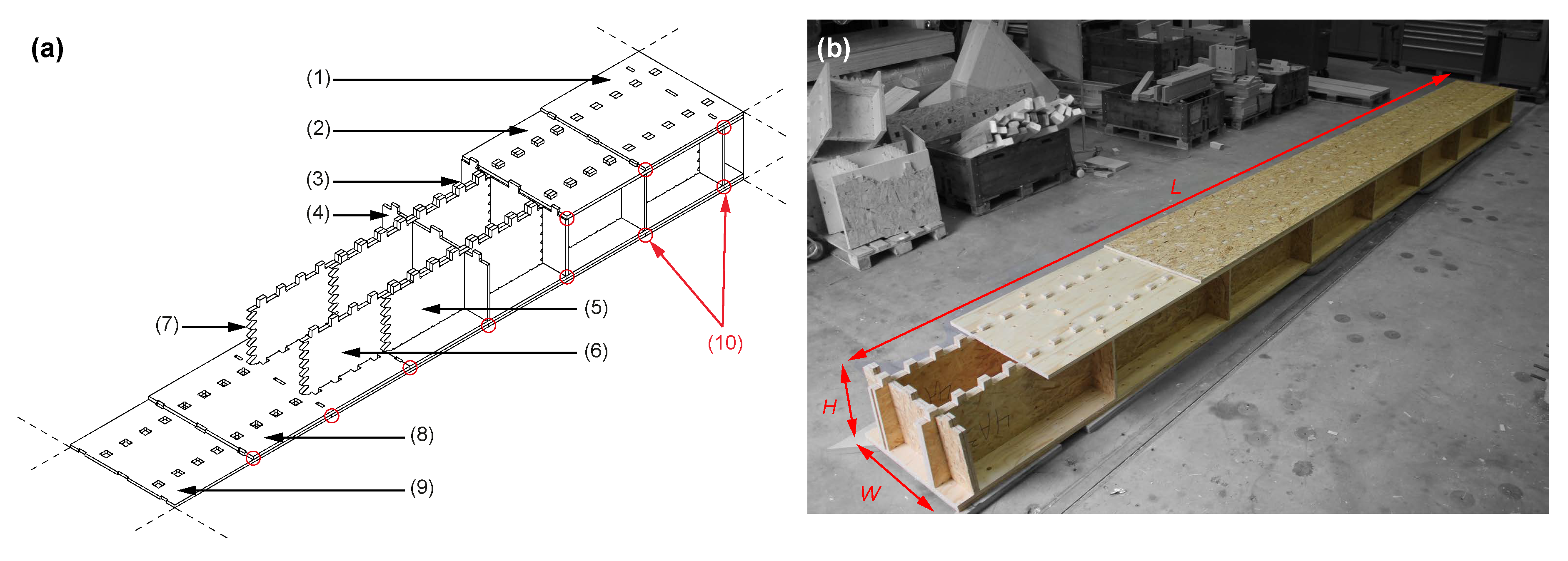
For this case study, three specimens were produced using spruce LVL and OSB. This system was developed through a technology transfer with a timber company; hence, the materials were chosen for the location, cost, and other specific reasons. Nevertheless, the concept remained the same, and different materials could be employed to enhance the overall performance of this type of structure. The elements were 8.4 m long (L), 0.8 m wide (W), and 0.45 m high (H), as shown in Figure 1b. The proposed structural element was composed of two parallel beam rows (webs) connected with two top and bottom panel layers (flanges) using through tenon (TT) joints [54] (Figure 1). All the panels were arranged in staggered rows with two layers to reconstitute the total length of the studied element with small-sized panels. Webs in the same row were also connected by finger joints (Figure 1a, 7) to improve the mechanical performance. The webs were made of OSB Type 3 panels with a thickness of 25 mm each (Figure 1a, 5, 6), while the flanges consisted of spruce LVL with a thickness of 21 mm (Figure 1a, 2, 8) and OSB Type 3 panels with a thickness of 18 mm (Figure 1a, 1, 9). There were 9 transversal beams in OSB distributed equally by 25 mm along the length and connected by TT joints as well (Figure 1a, 4). They were divided into three parts in order not to weaken the two longitudinal beams. The fiber orientation of each panel was along its length, and TT joints were directly machined in panels to connect all the different parts, as no bonding process was used. All the parts were cut with a 5-axis CNC machine without gaps and assembled by hand. All the panels had a common size of 1.25 by 2.5 m for supply, cost, and manufacturing reasons. A detailed plan, with all the necessary information to reproduce the specimens, can be found in Appendix A (Figure A1).
3.2. Methods
Tests were performed on these three large-scale specimens to study the mechanical behavior of this new type of structural system and to validate the calculation method proposed in Section 4.1. The bending properties, especially the effective bending stiffness (), were investigated, as they are the main area of interest for interconnected timber elements with semi-rigid connections. The specimens were produced with the geometry and materials described in Section 3.1. The panel density was tested according to EN 323 [55], whereas the other characteristics were obtained from EN 12369 [56] for OSB and from the VTT certificate [57] provided by the supplier for LVL. These values are listed in Table 1.
Four-point bending tests were performed following the standard EN 408 [58]. The experimental setup is presented in Figure 2. The test length (L) was 18 times the depth of the section with a total extra length of 300 mm. Specimens were simply supported with a span of 8.1 m (L). LVL beech plates of 40 mm thickness and 225 mm width were used as bearing plates and positioned at the supports along with the loading heads to minimize local indentation. Two hydraulic jacks symmetrically loaded the structure, and no lateral restraints were necessary. Two linear variable differential transformers (LVDT) were placed at each quarter of the span, on the top flange, to report the deflection resulting from bending moments. Furthermore, the digital image correlation (DIC) technique was used to record relative displacements caused by material discontinuities in four areas of the flange sections, as shown in Figure 2 (DIC 1, 2, 3, and 4) and Figure 1a (10, red circles). The effective bending stiffness, , was calculated according to Equation (1) described in EN 408 [58], Section 10.3:
where L is the span, F is the load in one hydraulic jack, and is the result of the load-deformation regression analysis. As it was the result of the total load applied, which was the sum of two hydraulic jacks, was divided by two.
In addition, 10 impulsive vibration tests per specimen were performed to estimate the initial natural frequency. From this frequency value, an alternative effective bending stiffness, , was calculated using Equation (2) described in EC5 [28]:
where L is the span, f is the measured natural frequency, and m the mass of the specimen. The formulation of Equation (2) does not take shear into account. The average specimen mass was 509 kg. Vibrations were triggered using a hammer, and two acceleration transducers (HBM B12/200) were positioned at mid-span with an acquisition speed rate of 200 Hz. The frequency spectrum was computed according to the fast Fourier transform (FFT) algorithm where the first peak represents the natural frequency (f) of the structural element, as shown in Figure 3b. Furthermore, the damping ratio, , was determined using the logarithmic decrement, . This method was precise enough to obtain damping ratios of under-damped systems in the time domain [59] and is characterized by Equations (3) and (4):
where is the value of the first studied peak value at time t and is the peak value at n periods away. In this case, the first and third peaks of each vibration test were used to compute the damping ratio (Figure 3a).
4. Calculation
As described in Section 2, there are different types of models for interconnected timber elements, but they were mainly developed for steel mechanical fasteners such as screws, nails, or bolts. Indeed, fasteners were one of the most used connections in the last few decades and still are currently. Only a few models were created for wood-wood connections. However, these connections were very different from the TT assembly studied here (mainly wood dowels and surface treatments). In addition, research was performed on continuous elements that were different from the developed structural element containing many discontinuities (Figure 1a, 10, red circles). As a result, an analytical method was difficult to establish for this type of element because of all these singularities, which were a function of panel geometries and other characteristics. On the other hand, FE models were often costly and time-consuming, as highlighted in Section 2, especially for basic building components developed in this research. In order to represent the complexity of this new structural system in the simplest way as possible, a numerical model only made of beam elements was developed inspired by strut-and-tie methods.
4.1. Proposed Calculation Method
The structural element presented in Section 3.1 had a symmetrical cross-section (see Figure A1, view DD’) and could be considered as two I-beams in parallel when studying its bending properties. Only one I-beam was thus modeled to facilitate the calculation. The proposed model is presented in Figure 4 with a complete description of the different parts in Table 2. It was composed of beam elements located at the centroid of each section (Figure 4a). They possessed the required information such as the section and material properties used to compute the different results. The different beam elements were connected together by rigid ties representing the inherent eccentricities due to the section properties. Rigid ties’ characteristics had no influence on the mechanical response.
Concerning the connections, they were usually represented by a shear stiffness in models, especially for mechanical fasteners and continuous elements. Different connectors, such as nails or bolts, were modeled only with springs without any section or material properties. However, a different approach was developed for the TT connection. The tenon part of the TT connection was modeled and represented by beam elements with the proper section and material information. The mortise part was also modeled with beam elements that possessed a reduced cross-section to take into account the hole in the flanges at its location. The semi-rigidity of the connection was taken into consideration with a spring between the contact area of the tenon and the mortise. The assembly gap could be implemented through a unidirectional displacement constraint on each spring. Figure 4c shows the different parts for the modeling of a TT connection with the proposed model, and all the detailed information is listed in Table 2 (description and element type). The friction, whether between contact surfaces or connections, was not considered with this method as it was hard to model and predict for such large-scale elements in practice. For now, the most important parameter to characterize for the proposed model was the spring in the contact area of the TT connection, as displayed in Figure 4c.
4.2. Stiffness Parameter for TT Connection
The mechanical characterization of the TT joint in the contact zone was essential to determine the stiffness value of the spring element in the calculation model presented in Figure 4c. Therefore, an experimental campaign was performed on this type of wood-wood connection with the specific parameters of the studied specimens.
4.2.1. Material and Methods
A total of 10 identical samples were produced with the same CNC machine used for the structural element to obtain a surface condition similar to the real application. The properties and geometry were chosen according to the structural system presented in Section 3.1. The panels used for these tests belonged to the same batch as those used for the tests presented in Section 3.2. The material and samples were conditioned in a normalized environment with a temperature of 20 C and relative humidity of 65% [60]. Tests were realized using a static universal testing machine (walter+bai ag, Model LFV-200) following the procedure described in EN 26891 [61] as it was the closest standard for this type of joint. Figure 5 shows the configuration of the experimental setup. The hydraulic jack applied pressure on the contact zone of 50 by 39 mm composed of OSB and LVL, while two LVDTs measured the deformation d within the range of the distance of 75 mm. The average of the two LVDTs was used to determine the final deformation and extract the contact stiffness. Finally, the grain orientation of the different panels was perpendicular to the contact zone as was the case for the structural element configuration.
4.2.2. Results
The experimental stiffness, , was defined by a linear regression analysis of the load-deformation response between 10 and 40% of the maximum load applied [61]. The experimental curves are presented in Figure 6. The average value for was 31.09 kN/mm, with a relative standard deviation of only 6%. It represented a good homogeneity considering these materials. Equation (5) defines the stiffness value for one spring element of the calculation model as one connection is divided into several spring elements (Figure 4c):
As a result, the value of 3.89 kN/mm was used to compute the semi-rigid (SR) calculation model. The geometry and the precision of the CNC cutting for the joint were chosen to assemble the different parts of the structural element without gaps. The initial stiffness shown in Figure 6 was higher than the value. It was not taken into consideration as it happened for very low load values and could be due to several reasons such material characteristics, manufacturing parameters, assembly gaps, and moisture content. It could also be a one time effect that happened only for the first loading of the connection and would not last over time. This phenomenon occurred for very low displacements from 0 to 0.1 mm and was thus complicated to assess easily considering the parameters influencing it. Consequently, was directly used for the calculation model, and no unidirectional displacement constraint was implemented. The failure mode and load-carrying capacity were not studied as the local behavior of the connection was not the main interest of this paper. Future research will be performed concerning the mechanical behavior of TT connections.
4.2.3. Parameter Values
The input parameter for the TT connection was based on the experimental results (SR model) as described in the two previous Section 4.2.1 and Section 4.2.2. However, two other values were used to assess the calculation model and study the influence of the semi-rigidity. One was a completely rigid model, named R, with an infinite stiffness in the contact area imitating a glued connection. Another one, named Optim., was based on a curve-fit from the large-scale bending test results presented in Section 5.1. The goal was to obtain the exact same mechanical response as the bending tests by adjusting the contact stiffness value of the Optim. model and comparing it to the value used in the SR model. Obviously, this Optim. model was just used for comparison and not to develop a reliable calculation methodology. To summarize, three different models were computed:
- The SR model using the value from connection tests (proposed calculation method of this study).
- The R model by not taking into consideration the semi-rigid behavior of TT connection (rigid model).
- The Optim. model just for the comparison of the stiffness values and its influence.
The input parameter, , of each case is listed in Table 3.
5. Results and Discussion
The results are presented in three parts: first, the effective bending stiffness, , as it was the main interest of this study; second, the effects of panel discontinuities, as it was a challenging part of the construction system; finally, the failure mode is briefly described to investigate potential areas of interest for future research.
5.1. Effective Bending Stiffness
Figure 7 shows the deflection at mid-span as a function of the total applied load. The specimens had an elastic linear behavior until failure. An average of the three replicates was determined by a linear regression up to the maximum force before failure to compare the of the tests and the different calculation models presented in Section 4.2.3. All the results are listed in Table 3.
For , the SR model was the closest calculation to the tests with a difference of −11.98%, whereas the R model was 41.75% more rigid. Considering a simple rigid model was not appropriate according to the large overestimation for the serviceability of this type of structure. It highlighted the importance of considering the stiffness of wood-wood connections for this type of element. The SR model was more adapted to estimate the bending stiffness and, therefore, the displacement of the element. Nevertheless, the SR model had a connection stiffness of approximately 37% lower than the Optim. model that perfectly represented the tests. The slip modulus difference, , in the most loaded connection for a load of 30 kN (approximate failure load) between the SR and Optim. model. was about 0.027 mm. It showed the high sensitivity of this criterion for the model. The precision of the experimental characterization of the TT connection was crucial to obtain an accurate prediction. Experimental protocols will be investigated and developed to obtain the most precise behavior for this type of wood-wood connections based on the work described in Section 4.2.1.
For the vibration tests, the detailed results of the 30 replicates for the natural frequency and the damping ratio could be examined in the open access data repository [62] (dataset). Concerning the natural frequency f, the average value for the three slabs was 9.89 Hz with a coefficient of variation of 2.18%. The effective bending stiffness, , obtained from this result and Equation (2), was equal to MPa·mm4, while , from the bending test, was MPa·mm4. As a result, the bending stiffness estimated from the vibration tests was 37.89% higher than the bending tests. The low amplitude of the vibration tests, triggered only by the hammer, could explain this difference. Loads in connections were then very low compared to those of the bending tests, and as a consequence, the initial stiffness described in Section 4.2.2 (Figure 6) was activated. The connections were thus stiffer with the low intensity loads of the vibration tests. The rigid model was the closest to the natural frequency tested, whereas the SR and Optim. models were respectively −15.17% and −9.50% lower. The manufacturing parameters were important for the assembly process, but also for the prediction of the structural behavior as they influenced the initial stiffness of the connection. In addition, the average damping ratio of the three specimens, , was 2.05% with a coefficient of variation of 4.39%. The very conservative value of damping ratio defined in EC5 [28] for timber floors was 1%. Nevertheless, several European national application documents gave values around 2% [63], such as the U.K. [64]. In Annex B of the standard ISO 10137 [65], the recommended value for bare timber floor is 2% and the typical range is between 1.5 and 4%. The value determined during the tests corresponded to typical timber floor damping ratios. Therefore, there was no more exceptional friction in this type of construction system than in traditional timber floors, which confirmed the choice not to model friction in the calculation model.
Overall, the difference between the tests and the proposed SR model could be explained mainly with the sensitivity of the contact stiffness criterion, which was influenced by the intensity of loads in connections, material characteristics, manufacturing parameters, assembly gaps, and moisture content. However, the SR model remained on the safe side of the design by being slightly lower compared to the tests and retained the ease of use for practice. The model could be enhanced with a more accurate prediction of the TT connection behavior and the exploration of the effect of manufacturing parameters on the structural performance.
5.2. Panel Discontinuities
Figure 8 illustrates the displacements caused by flange discontinuities for the tests and the SR model at the specific positions on the specimens as described in Figure 2. Negative displacements represented flanges in compression as they moved closer, while positive displacements represented flanges in tension as they moved apart. The highest displacement reached 2 mm in the tension flange located under the hydraulic jack (Figure 8c), where the SR model had the highest error with a drift of 0.5 mm. Otherwise, for flanges in tension, the calculation model remained within a maximum error range of 0.2 mm and with a good correlation for displacements in the middle of the specimens (Figure 8b). For compression flanges, a contact could occur between 0.5 and 1.5 mm when they touched each other, as observed twice during these tests (Figure 8b,c). Assembly tolerances, shrinkage and swelling spacing, material variability, and other parameters had an influence on this phenomenon, which was complicated to estimate in advance. As a result, no displacement limitation was considered for the SR model, and it could explain these differences when contact occurred. Based on experience and fabrication knowledge, a limit for this parameter could be considered as the input to improve the SR model. Finally, the SR model provided a good approximation of the displacements between panel discontinuities considering the small range of displacement.
5.3. Failure Mode in Tension
Although it was not the main objective of the paper, a few remarks can be made concerning the failure mode of this type of elements. A brittle failure in tension was observed in the middle of all the specimens and was located in the OSB bottom flange. It is well known that a low width-to-thickness ratio of flanges has a substantial influence on the resistance of long elements and on the failure mode of this type of construction system. It causes a non-uniform stress distribution along flange elements called shear lag. This phenomenon is influenced by several factors such as material shear properties, boundary conditions, type of loading, and the ratio of flange width-to-span length. However, European timber standards [28,66] deal with shear lag by changing the physical cross-section dimensions with an effective width defined only by a constant ratio of the span, regardless of the other factors. Equation (6) defines the effective width for our case following the current standard:
where is the effective width and L is the span.
Figure 9 shows the failure profiles of the OSB flanges. The estimated failure profiles were not respected in the different cases, which was probably caused by the higher variability of OSB panels compared to other engineered timber panels. The exact length of the failure profile () was determined to better interpret the results. The average tensile strength parallel to the fiber direction of OSB 3 was calculated using Equation (7), according to Section 7.2.7 of the Swiss standard for timber structures [66]. In addition, the maximum tensile strength () and the shear lag coefficient (U) of each specimen were calculated according to Equations (8) and (9), respectively:
where is the average tensile strength parallel to the fiber direction, is its characteristic fifth-percentile value, is the maximum tensile load in the OSB bottom flange obtained from the calculation model when the failure occurred, is the exact failure length, and is the panel thickness of the OSB bottom flange (constant value of 18 mm).
The results are listed in Table 4. Although the failure length was lower than the effective width calculated, the tensile strength was approximately two-times less resistant than expected. It was thus difficult to establish that Equation (6) was sufficient to approximate the shear lag coefficient for this type of structural system. In addition to the inherent complexity of this phenomenon, there were parts of the panels cut into flanges for the TT connections that could change the expected behavior and, as a consequence, complicate the calculation. As the tensile properties were not characterized by tests and considering the variability of OSB, the results should be treated with caution. These results simply gave a first overview of a possible failure mode due to shear lag and highlighted the importance of further investigations. Finally, other material types could be used to avoid a brittle failure in the lower flange and enhance the overall structural performance. OSB panels were chosen according to a case study for several specific reasons, as mentioned earlier.
6. Conclusions
This paper presented a newly developed concept of standard structural elements using only through tenon connections with the idea of flat-packs directly delivered and assembled on site, like a building kit for housing. Three large-scale specimens were manufactured with spruce LVL and OSB panels, but different materials could be used to enhance and optimize such a construction system. According to commonly available dimensions from suppliers, small-sized panels were used to reconstitute a span of 8.1 m. The reproducibility of the CNC manufacturing process and assembly process by hand was validated with a small variation between the three specimens observed during the tests. As no bonding was applied, there were several discontinuities along the length of elements that complicated the prediction of the structural response in addition to the semi-rigid behavior of TT connections.
Although elastic analytical methods are generally convenient to use in practice for semi-rigid connections, they cannot take into consideration these types of discontinuities in a simple manner. A suitable numerical calculation method was thus developed to address this issue through the application of beam elements in the elastic range, such as strut-and-tie models. The semi-rigidity of TT connections was taken into consideration with spring elements defined by experimental tests. The effective bending stiffness of the specimens, which played a major role in the structural design of interconnected timber elements, was measured and compared to the proposed calculation model (SR). Furthermore, two other models were defined to evaluate the influence of different parameters, especially the connection: a rigid model (R) and a model based on the bending experimental results (Optim.).
The results demonstrated that the proposed methodology was effective to predict the mechanical behavior of this new type of element in a convenient manner without costly engineering models. The SR model captured accurately the different discontinuities along the length of the elements and input parameters, such as displacement limitations for flanges in compression could improve the model response. The effective bending stiffness predicted by the SR model was slightly lower compared to the average value obtained from the tests. The large overestimation of the rigid model R and the displacement difference in the most loaded connection between the SR and Optim. models emphasized the importance to take into consideration the semi-rigidity of TT connections. This could be characterized by elementary tests on the studied connections.
Moreover, the estimated bending stiffness based on the natural frequency value was different compared to the one obtained from the bending tests. The initial contact stiffness value, which was stiffer than the slip modulus, could explain this variation because of the low intensity of loads during the vibration tests. This phenomenon occurred for very low displacements from 0 to 0.1 mm and was thus very hard to estimate easily considering the parameters influencing it (material characteristics, manufacturing parameters, assembly gaps, moisture content). However, the long-term effect of this phenomenon was unknown, and it might not last over time, placing the model on the safe side of the design. The damping ratio was in the range of typical timber floor values and proved that the effect of friction between the elements could be neglected. As a result, the friction was not considered in the model, as it is usually the case in practice for timber structural elements.
Considering the failure modes, tensile failures in the bottom flanges due to the brittle characteristics of OSB were observed. Differences in the expected maximum strength were pointed out due to stress concentration. Thus, shear lag phenomenon should be investigated more precisely as the tensile properties were not characterized for these tests.
Finally, with simple experimental tests on connections, the proposed calculation model was a practical methodology to obtain the stress distribution and the global displacements of interconnected elements using TT joints. Nevertheless, complementary works remain to be realized to properly design these elements for the construction market according to building codes: (i) verify the long-term beneficial effect of the initial contact stiffness on the vibration properties; (ii) study the creep effect of connections and its influence on the global behavior; (iii) establish the resistance and failure mode criteria of connections for different timber engineered panels ordinarily used in industry; (iiii) estimate the influence of holes in flanges due to the mortise part of the connection on the shear lag phenomenon.
Author Contributions
Conceptualization, J.G., J.F.B., and Y.W.; methodology, J.G. and J.F.B.; validation, J.G. and J.F.B.; formal analysis, J.G. and J.F.B.; investigation, J.G.; data curation, J.G.; writing, original draft preparation, J.G.; writing, review and editing, J.G., J.F.B., and Y.W.; visualization, J.G.; supervision, J.F.B. and Y.W.; project administration, J.G.; funding acquisition, Y.W. All authors have read and agreed to the published version of the manuscript.
Funding
This research was supported by the National Centre of Competence in Research for Digital Fabrication, funded by the Swiss National Science Foundation (NCCR Digital Fabrication Agreement #51NF40-141853).
Acknowledgments
The authors would like to thank Martin Nakad from the Laboratory for Timber Constructions (IBOIS, EPFL) for his valuable contribution to this work. The authors would also like to acknowledge the support and assistance of the Structural Engineering Group of EPFL.
Conflicts of Interest
The authors declare no conflict of interest.
Abbreviations
The following abbreviations are used in this manuscript:
| IMA | Integral mechanical attachments |
| CNC | Computer numerical control |
| CAD | Computer-aided design |
| CAM | Computer-aided manufacturing |
| FE | Finite element |
| OSB | Oriented strand board |
| LVL | Laminated veneer lumber |
| GLT | Glued laminated timber |
| CLT | Cross-laminated timber |
| Effective bending stiffness | |
| EC5 | Eurocode 5 |
| TT | Through tenon |
| DIC | Digital image correlation |
| LVDT | Linear variable differential transformers |
| f | Natural frequency |
| Damping ratio | |
| Logarithmic decrement | |
| FFT | Fast Fourier transform |
| Connection stiffness value for one joint |
Appendix A. Detailed Plan of Large-Scale Specimens
Figure A1.
Detailed plan of large-scale specimens.

References
- Robeller, C. Integral Mechanical Attachment for Timber Folded Plate Structures. Ph.D. Thesis, École Polytechnique Fédérale de Lausanne, Lausanne, Switzerland, 2015. [Google Scholar] [CrossRef]
- Robeller, C. Timber Plate Shell Structures: A Digital Resurgence of Traditional Joining Methods. In Digital Wood Design: Innovative Techniques of Representation in Architectural Design; Springer International Publishing: New York, NY, USA, 2019; pp. 1117–1133. [Google Scholar] [CrossRef]
- Robeller, C.; Weinand, Y. A 3d cutting method for integral 1DOF multiple-tab-and-slot joints for timber plates, using 5-axis CNC cutting technology. In Proceedings of the World Conference of Timber Engineering WCTE, Vienna, Austria, 22–25 August 2016. [Google Scholar]
- Schwinn, T.; Krieg, O.D.; Menges, A. Robotically Fabricated Wood Plate Morphologies. In RobArch 2012: Robotic Fabrication in Architecture, Art, and Design; Springer: Vienna, Austria, 2013; pp. 48–61. [Google Scholar] [CrossRef]
- Li, J.M.; Knippers, J. Segmental Timber Plate Shell for the Landesgartenschau Exhibition Hall in Schwäbisch Gmünd—The Application of Finger Joints in Plate Structures. Int. J. Space Struct. 2015, 30, 123–139. [Google Scholar] [CrossRef]
- Robeller, C.; Gamerro, J.; Weinand, Y. Théâtre Vidy Lausanne—A Double-Layered Timber Folded Plate Structure. J. Int. Assoc. Shell Spatial Struct. 2017, 58, 295–314. [Google Scholar] [CrossRef]
- Buri, H.U. Origami—Folded Plate Structures. Ph.D. Thesis, École Polytechnique Fédérale de Lausanne, Lausanne, Switzerland, 2010. [Google Scholar] [CrossRef]
- Robeller, C.; Stitic, A.; Mayencourt, P.; Weinand, Y. Interlocking Folded Plate—Integrated Mechanical Attachment for Structural Timber Panels. Adv. Arch. Geom. 2014, 4, 281–294. [Google Scholar] [CrossRef] [Green Version]
- Robeller, C.; Nabaei, S.S.; Weinand, Y. Design and Fabrication of Robot-Manufactured Joints for a Curved-Folded Thin-Shell Structure Made from CLT. In Robotic Fabrication in Architecture, Art and Design 2014; Springer: Cham, The Netherlands, 2014; pp. 67–81. [Google Scholar] [CrossRef] [Green Version]
- Stitic, A.; Nguyen, A.C.; Rezaei Rad, A.; Weinand, Y. Numerical Simulation of the Semi-Rigid Behaviour of Integrally Attached Timber Folded Surface Structures. Buildings 2019, 9, 55. [Google Scholar] [CrossRef] [Green Version]
- Nguyen, A.C.; Vestartas, P.; Weinand, Y. Design framework for the structural analysis of free-form timber plate structures using wood-wood connections. Autom. Constr. 2019, 107, 102948. [Google Scholar] [CrossRef]
- Roche, S.N. Semi-Rigid Moment-Resisting Behavior of Multiple Tab-and-Slot Joint for Freeform Timber Plate Structures. Ph.D. Thesis, École Polytechnique Fédérale de Lausanne, Lausanne, Switzerland, 2017. [Google Scholar] [CrossRef]
- Stitic, A.; Robeller, C.; Weinand, Y. Experimental investigation of the influence of integral mechanical attachments on structural behaviour of timber folded surface structures. Thin-Walled Struct. 2018, 122, 314–328. [Google Scholar] [CrossRef]
- Sass, L. A Wood Frame Grammar: A Generative System for Digital Fabrication. Int. J. Arch. Comput. 2006, 4, 51–67. [Google Scholar] [CrossRef]
- Sass, L.; Botha, M. The Instant House: A Model of Design Production with Digital Fabrication. Int. J. Arch. Comput. 2006, 4, 109–123. [Google Scholar] [CrossRef]
- WikiHouse Project, Open Systems Lab©, England. Available online: https://www.wikihouse.cc (accessed on 18 February 2020).
- Smith, S. Wikihouse 4.0: Towards a Smart Future; IABSE Symposium Report; International Association for Bridge and Structural Engineering: Geneva, The Netherlands, 2015; Volume 105, pp. 1907–1912. [Google Scholar]
- Albright, D.; Blouin, V.; Harding, D.; Heine, U.; Huette, N.; Pastre, D. Sim[PLY]: Sustainable Construction with Prefabricated Plywood Componentry. Procedia Environ. Sci. 2017, 38, 760–764. [Google Scholar] [CrossRef]
- Finch, G.; Marriage, G.; Gjerde, M.; Pelosi, A. Experiments in Timber Space Frame Design: Fabrication, Construction and Structural Performance. In Proceedings of the 24th International Conference on Computer-Aided Architectural Design Research in Asia (Caadria 2019), Victoria University of Wellington, Wellington, New Zealand, 15–18 April 2019; pp. 153–162. [Google Scholar]
- Al-Qaryouti, Y.; Gattas, J.M.; Shi, R.; McCann, L. Digital fabrication strategies for timber thin-walled sections. In WIT Transactions on the Built Environment, Proceedings of the 2nd International Conference on High Performance and Optimum Design of Structures and Materials (HPSM 2016), Siena, Italy, 19–21 September 2016; WIT Press: Ashurst, Southampton, UK, 2016; Volume 166, pp. 415–426. [Google Scholar] [CrossRef] [Green Version]
- Gattas, J.; You, Z. Design and digital fabrication of folded sandwich structures. Autom. Constr. 2016, 63, 79–87. [Google Scholar] [CrossRef]
- Natterer, J. Analyse Non-Linéaire des Coques Géodésiques Multicouches À Joints Semi-Rigides. Ph.D. Thesis, École Polytechnique Fédérale de Lausanne, Lausanne, Switzerland, 2010. [Google Scholar] [CrossRef]
- Möhler, K. Über einige Grundlagen und Entwicklungsmöglichkeiten des Holznagelbaues. Holz als Roh- und Werkstoff 1955, 13, 388–397. [Google Scholar] [CrossRef]
- Möhler, K. Über das Tragverhalten von Biegeträgern und Druckstäben mit Zusammengesetztem Querschnitt und Nachgiebigen Verbindungsmitteln. Ph.D. Thesis, Karlsruhe Institute of Technology, Karlsruhe, Germany, 1956. [Google Scholar]
- Schelling, W. Die Berechnung nachgiebig verbundener, zusammengesetzter Biegeträger. Ingenieurholzbau 1968. [Google Scholar]
- Schelling, W. Zur Berechnung nachgiebig zusammengesetzter Biegeträger aus beliebig vielen Einzelquerschnitten. In Ingenieurholzbau in Forschung und Praxis; Bruderverlag: Karlsruhe, Germany, 1982; pp. 155–162. [Google Scholar]
- Heimeshoff, B. Zur Berechnung von Biegeträgern aus nachgiebig miteinander verbundenen Querschnittsteilen im Ingenieurholzbau. Holz als Roh- und Werkstoff 1987, 45, 237–241. [Google Scholar] [CrossRef]
- EN 1995-1-1:2005. European Committee for Standardization. Eurocode 5: Design of Timber Structures—Part1-1: General-Common Rules and Rules for Buildings; European Committee for Standardization: Brussels, Belgium, 2014. [Google Scholar]
- Girhammar, U.A. A simplified analysis method for composite beams with interlayer slip. Int. J. Mech. Sci. 2009, 51, 515–530. [Google Scholar] [CrossRef]
- Kreuzinger, H. Flächentragwerke: Platten, Scheiben, Schalen, Berechnungsmethoden und Beispiele. In Informationsdienst Holz, Brücken aus Holz; 1999; pp. 43–60. [Google Scholar]
- Scholz, A. Ein Beitrag zur Berechnung von Flächentragwerken aus Holz. Ph.D. Thesis, Technische Universität München, München, Germany, 2003. [Google Scholar]
- Scholz, A. Eigenspannungszustände an Verbundquerschnitten infolge von Dehnungsunterschieden— Anwendung eines neueren Rechenverfahrens auf einen bewährten Lösungsansatz. Bautechnik 2004, 81, 180–188. [Google Scholar] [CrossRef]
- German Institute for Standardisation. Design of Timber Structures—General Rules and Rules for Buildings; German Institute for Standardisation: Berlin, German, 2004. [Google Scholar]
- Kreuzinger, H.; Blass, H.J. Calculation Models for Prefabricated Wood-Based Load Bearing Stressed Skin Panels for Use in Roofs; Technical Report TR 019; European Organisation for Technical Approvals: Brussels, Belgium, 2005. [Google Scholar]
- Hoeft, M. Zur Berechnung von Verbundträgern mit Beliebig Gefügtem Querschnitt. Ph.D. Thesis, École Polytechnique Fédérale de Lausanne, Lausanne, Switzerland, 1994. [Google Scholar] [CrossRef]
- Krawczyk, P. Nonlinear Analysis of Layered Structures with Weak Interfaces. Ph.D. Thesis, École Polytechnique Fédérale de Lausanne, Lausanne, The Netherlands, 2006. [Google Scholar] [CrossRef]
- Krawczyk, P.; Frey, F.; Zielinski, A. Large deflections of laminated beams with interlayer slips. Eng. Comput. 2007, 24, 17–32. [Google Scholar] [CrossRef]
- Gollwitzer, T.; Gebbeken, N. A new Beam-Finite-Element for flexible bond in composite sections [Ein neues FEM-Stabelement für nachgiebige Verbundquerschnitte]. Bautechnik 2004, 81, 549–554. [Google Scholar] [CrossRef]
- Pirazzi, C. Zur Berechnung von Holzschalen in Brettrippenbauweise mit Elastischem Verbundquerschnitt. Ph.D. Thesis, École Polytechnique Fédérale de Lausanne, Lausanne, The Netherlands, 2005. [Google Scholar] [CrossRef]
- Martin, P. Etude du Comportement des Poutres Lamellées Clouées Boulonnées en Flexion. Ph.D. Thesis, ENGREF (AgroParisTech), Paris, France, 2006. [Google Scholar]
- Resch, L. Développement D’éléments de Construction en bois de pays Lamellés Assemblés par Tourillons Thermo-Soudés. Ph.D. Thesis, École Nationale Supérieure des Technologies et Industries du Bois, Épinal, France, 2009. Available online: http://www.theses.fr/2009NAN10142 (accessed on 6 January 2020).
- Girardon, S.; Barthram, C.; Resch, L.; Bocquet, J.F.; Triboulot, P. Determination of shearing stiffness parameters to design multi-layer spruce beams using welding-through wood dowels. Eur. J. Wood Wood Prod. 2014, 72, 721–733. [Google Scholar] [CrossRef]
- O’Loinsigh, C.; Oudjene, M.; Shotton, E.; Pizzi, A.; Fanning, P. Mechanical behaviour and 3D stress analysis of multi-layered wooden beams made with welded-through wood dowels. Compos. Struct. 2012, 94, 313–321. [Google Scholar] [CrossRef] [Green Version]
- Girardon, S. Amélioration des Performances Mécaniques des Assemblages bois sur bois Vissés par Préparation des Interfaces: Application à la Réalisation D’éléments de Structure. Ph.D. Thesis, École Nationale Supérieure des Technologies et Industries du Bois, Épinal, France, 2014. Available online: http://www.theses.fr/2014LORR0188/document (accessed on 6 January 2020).
- Girardon, S.; Bocquet, J.F. Mechanical behaviour of pre-stressed spruce timber–timber 2.5-mm-step grooved connections under shearing tests. Eur. J. Wood Wood Prod. 2017, 75, 719–727. [Google Scholar] [CrossRef]
- Roche, S.; Robeller, C.; Humbert, L.; Weinand, Y. On the semi-rigidity of dovetail joint for the joinery of LVL panels. Eur. J. Wood Wood Prod. 2015, 73, 667–675. [Google Scholar] [CrossRef]
- Kenel, A. Zur Berechnung von Holz/Beton-Verbundkonstruktionen: Entwicklung und Vergleich Verschiedener Berechnungsmethoden; Forschungs- und Arbeitsberichte/Abteilung 115, Holz EMPA; EMPA: Dübendorf, Switzerland, 2000; Volume 115/42. [Google Scholar]
- Grosse, M.; Hartnack, R.; Lehmann, S.; Rautenstrauch, K. Modellierung von diskontinuierlich verbundenen Holz-Beton-Verbundkonstruktionen/Teil 1: Kurzzeittragverhalten. Bautechnik 2003, 80, 534–541. [Google Scholar] [CrossRef]
- Michelfelder, B.C. Structural and Deformation Behaviour of Grooves in Composites of Nail-Laminated Board Stacks and Concrete. Ph.D. Thesis, Institut für Konstruktion und Entwurf, University of Stuttgart, Stuttgart, Germany, 2006. [Google Scholar]
- Dias, A.; Schänzlin, J.; Dietsch, P. Design of Timber-Concrete Composite Structures a State-of-the-Art Report by COST Action FP1402/ WG 4.; Shaker Verlag GmbH. 2018. Available online: https://www.costfp1402.tum.de/en/publications/ (accessed on 6 January 2020).
- Hehl, S.; Tannert, T.; Meena, R.; Vallee, T. Experimental and Numerical Investigations of Groove Connections for a Novel Timber-Concrete-Composite System. J. Perform. Constr. Facil. 2014, 28, A4014010. [Google Scholar] [CrossRef]
- Bedon, C.; Fragiacomo, M. Three-dimensional modelling of notched connections for timber-concrete composite beams. Struct. Eng. Int. J. Int. Assoc. Bridge Struct. Eng. (IABSE) 2017, 27, 184–196. [Google Scholar] [CrossRef]
- Fragiacomo, M. A finite element model for long-term analysis of timber-concrete composite beams. Struct. Eng. Mech. 2005, 20, 173–189. [Google Scholar] [CrossRef]
- Roche, S.; Gamerro, J.; Weinand, Y. Multiple Tab-and-Slot Joint: Improvement of the Rotational Stiffness for the Connection of Thin Structural Wood Panels. In Proceedings of the World Conference on Timber Engineering (WCTE), Vienna, Austria, 22–25 August 2016. [Google Scholar] [CrossRef]
- European Committee for Standardization. Wood-Based Panels. Determination of Density; European Committee for Standardization: Brussels, Belgium, 1993. [Google Scholar]
- European Committee for Standardization. Wood-Based Panels. Characteristic Values for Structural Design—Part 1: OSB, Particleboards and Fiberboards; European Committee for Standardization: Brussels, Belgium, 2001. [Google Scholar]
- VTT Technical Research Centre of Finland. Certificate No. 184/03 for Structural Laminated Veneer Lumber, 2004. Updated 17 May 2016. Available online: https://www.metsawood.com/global/Tools/MaterialArchive/MaterialArchive/Kerto-VTT-C-184-03-Certificate.pdf (accessed on 6 January 2020).
- European Committee for Standardization. Timber Structures—Structural Timber and Glued Laminated Timber—Determination of Some Physical and Mechanical Properties; European Committee for Standardization: Brussels, Belgium, 2010. [Google Scholar]
- Thorby, D. 5—Damping. In Structural Dynamics and Vibration in Practice; Thorby, D., Ed.; Butterworth-Heinemann: Oxford, UK, 2008; pp. 99–118. [Google Scholar] [CrossRef]
- International Organization for Standardization. Standard Atmospheres for Conditioning and/or Testing—Specifications; American National Standards Institute (ANSI): Washington, DC, USA, 2007. [Google Scholar]
- European Committee for Standardization. Timber Structures—Joints Made with Mechanical Fasteners—General Principles for the Determination of Strength and Deformation Characteristic; European Committee for Standardization: Brussels, Belgium, 1991. [Google Scholar]
- Julien, G.; Bocquet, J.F.; Weinand, Y. Vibration tests on interconnected timber elements using wood-wood connections. Mendeley Data 2019, v1. [Google Scholar] [CrossRef]
- Zhang, B.; Rasmussen, B.; Jorissen, A.; Harte, A. Comparison of vibrational comfort assessment criteria for design of timber floors among the European countries. Eng. Struct. 2013, 52, 592–607. [Google Scholar] [CrossRef]
- British Standards Institution. UK National Annex to Eurocode 5: Design of Timber Structures—Part 1-1: General—Common Rules and Rules for Buildings; British Standards Institution: London, UK, 2006. [Google Scholar]
- International Organization for Standardization. Bases for Design of Structures–Serviceability of Buildings and Walkways against Vibrations; International Organization for Standardization: Geneve, The Netherlands, 2007. [Google Scholar]
- Swiss Society of Engineers and Architects. Timber Structures. Swiss Society of Engineers and Architects; Swiss Society of Engineers and Architects: Zurich, The Netherlands, 2012. [Google Scholar]
Figure 1.
(a) Developed construction system: (1) top flange exterior layer, (2) top flange interior layer, (3) through tenon (TT) connection, (4) transversal beam, (5) web first layer, (6) web second layer, (7) longitudinal connection for web, (8) bottom flange interior layer, (9) bottom flange exterior layer, (10) discontinuities due to panel sizes. (b) Picture of one specimen produced in the laboratory.

Figure 2.
Four-point bending test setup for large-scale specimens. DIC, digital image correlation.

Figure 3.
Vibration test on one specimen: (a) acceleration at mid-span over time; (b) frequency spectrum of the acceleration.
Figure 3.
Vibration test on one specimen: (a) acceleration at mid-span over time; (b) frequency spectrum of the acceleration.

Figure 4.
(a) Representation of the proposed calculation model (black lines) for the I-beam using TT connections (3D grey solid). (b) Axonometry of one TT joint. (c) Modeling of this joint with beam elements and springs.
Figure 4.
(a) Representation of the proposed calculation model (black lines) for the I-beam using TT connections (3D grey solid). (b) Axonometry of one TT joint. (c) Modeling of this joint with beam elements and springs.

Figure 5.
(a) Axonometry of the experimental setup for TT joints. (b) Side view. (c) Photo of the experimental setup with LVDTs.
Figure 5.
(a) Axonometry of the experimental setup for TT joints. (b) Side view. (c) Photo of the experimental setup with LVDTs.

Figure 6.
Experimental curves for TT connection tests.

Figure 7.
Deflection-load curves at mid-span for tests and calculation models. SR, semi-rigid; R, rigid.
Figure 7.
Deflection-load curves at mid-span for tests and calculation models. SR, semi-rigid; R, rigid.

Figure 8.
Displacement comparison between the tests and SR model caused by flange discontinuities.

Figure 9.
Tensile failure profile of OSB bottom flange panels.


Table 1.
Material properties.
| Designation | Symbol | Units | LVL Q | OSB 3 | |
|---|---|---|---|---|---|
| Thickness | - | mm | 21 | 18 | 25 |
| Position | - | - | flat-wise | flat-wise | edge-wise |
| Density | kg/m | 481 | 576 | 600 | |
| Elastic modulus to grain | N/mm | 10,000 | 4930 | 3800 | |
| Elastic modulus ⊥ to grain | N/mm | 3300 | 1980 | 3000 | |
| Shear modulus to grain | N/mm | 60 | 50 | 1080 | |
| Lay-up | - | - | |||
Table 2.
Model properties according to Figure 4.
Table 2.
Model properties according to Figure 4.
| ID Figure 4 | Section | Material | Description | Element Type |
|---|---|---|---|---|
| - | mm | - | - | - |
| (1) | 372/25 | OSB 3 | Web | Beam element |
| (2) | 18/175 | OSB 3 | Top flange ext.with reduced section due to the connection | Beam element |
| (3) | 50/25 | OSB 3 | Tenon | Beam element |
| (4) | - | - | Stiffness between the tenon and the flange | Spring element |
| (4)’ | - | - | Unidirectional displacement constraint for assembly gap | Parameter |
| (5) | 18/400 | OSB 3 | Top flange ext. without reduced section | Beam element |
| (6) | 21/400 | LVL Q | Top flange int.without reduced section | Beam element |
| (7) | 21/175 | LVL Q | Top flange int. with reduced section due to the connection | Beam element |
| (8) | - | - | Eccentricities due to the TT connection | Rigid tie |
| (9) | - | - | Eccentricities between tenon element and web element | Rigid tie |
Table 3.
Results of effective bending stiffness () and natural frequency (f).
| ID | * | f | * | ||
|---|---|---|---|---|---|
| - | (kN/mm) | (MPa.mm4) | (%) | (Hz) | (%) |
| Tests | - | 0 | 9.89 | 0 | |
| Model SR | 3.89 | −11.98 | 8.39 | −15.17 | |
| Model Optim. | 6.16 | 0 | 8.95 | −9.50 | |
| Model R | ∞ | 41.75 | 10.65 | 7.68 |
* Differences compared to the tests.
Table 4.
Results for tensile failure in the OSB bottom flange for each specimen.
| ID | U | |||
|---|---|---|---|---|
| - | (kN) | (mm) | (MPa) | - |
| Spec.01 | 66.44 | 627.5 | 5.88 | 1.88 |
| Spec.02 | 55.70 | 585 | 5.29 | 2.09 |
| Spec.03 | 60.10 | 680 | 4.91 | 2.25 |
| Av. | 60.75 | 630.08 | 5.36 | 2.07 |
© 2020 by the authors. Licensee MDPI, Basel, Switzerland. This article is an open access article distributed under the terms and conditions of the Creative Commons Attribution (CC BY) license (http://creativecommons.org/licenses/by/4.0/).
Share and Cite
MDPI and ACS Style
Gamerro, J.; Bocquet, J.F.; Weinand, Y. A Calculation Method for Interconnected Timber Elements Using Wood-Wood Connections. Buildings 2020, 10, 61. https://doi.org/10.3390/buildings10030061
AMA Style
Gamerro J, Bocquet JF, Weinand Y. A Calculation Method for Interconnected Timber Elements Using Wood-Wood Connections. Buildings. 2020; 10(3):61. https://doi.org/10.3390/buildings10030061
Chicago/Turabian StyleGamerro, Julien, Jean François Bocquet, and Yves Weinand. 2020. "A Calculation Method for Interconnected Timber Elements Using Wood-Wood Connections" Buildings 10, no. 3: 61. https://doi.org/10.3390/buildings10030061
Note that from the first issue of 2016, this journal uses article numbers instead of page numbers. See further details here.