Physical Modelling of the Ball-Rolling Processes


Mechanical Faculty, Lublin University of Technology, 36 Nadbystrzycka Str., 20-618 Lublin, Poland
*
Author to whom correspondence should be addressed.
Metals 2019, 9(1), 35; https://doi.org/10.3390/met9010035
Submission received: 22 November 2018
/
Revised: 18 December 2018
/
Accepted: 27 December 2018
/
Published: 4 January 2019
Abstract
:The objective of the article was to present the state of the problem of physical modelling of the hot-working processes with plasticine as the model material. It was stated that the aforementioned method can prove helpful in analyzing complex plastic forming processes such as cross rolling and helical rolling of balls. In order to confirm this hypothesis, an attempt at forming steel balls with diameters of 40 mm (cross rolling) and 57 mm (helical rolling) under laboratory conditions was made. Further on, these processes were conducted in model form using special model rolling mills and 3D printed acrylonitrile butadiene styrene (ABS) tools. The comparison of the test results regarding shape and manufacturing accuracy, as well as force parameters, confirmed the validity of using physical modelling in the investigation of the process of cross rolling and helical rolling of balls.
1. Introduction
Steel balls are widely used as grinding medium in mills for grinding materials such as metallic ores, coal, gravel, or used molding sand. Hot-working and, above all, die forging and rolling are used in their production.
Ball rolling appears to be the most effective method and can be performed as helical rolling (HR) or cross rolling (CR), although the former is used more frequently in industrial practice. It is claimed that the most problematic aspect of implementing the processes of ball rolling is designing the proper shape of tools (rolls or flat jaws). The basic recommendations concerning this issue were presented in specialist literature a long time ago, for example, in the works of Wang et al. [1] or Yang & Chen [2]. The process of cross rolling of balls, however, was discussed just recently, with its bases introduced by Pater [3].
Further development of the ball-rolling processes is linked to the possibility of using Finite Element Method (FEM)-based numerical modelling in their analysis. Recently, several works on this subject were published. Thus, Pater et al. [4] introduced a new variant of the HR process based on the numerical simulations. In this process, balls are hot formed by rolls with helically wound wedges. Cao et al. [5] conducted an analysis of the stress and strain state in small diameter balls, cold formed in the process of helical rolling. Furthermore, Pater et al. [6] introduced an innovative technology of cross rolling balls with a diameter of 70 mm, manufactured from heads of scrapped rails. In the above-mentioned works, the commercial programme Simufact Forming was used. The software did not, however, allow for the simulation of the separation of balls and, therefore, a simplification in the form of leaving a small-diameter connector between adjacent balls was made. In order to remove the occurring limitation, it was necessary to determine how helpful physical modelling is with plasticine as the model material in an analysis of ball rolling. The results of the research on this subject are presented in this article.
Physical modelling with plasticine as model material was widely used in analyses of the processes of plastic forming in the late 20th century, that is, in the period during which numerical modelling of complex cases of forming was not yet possible. This phenomenon can be observed in the works of Japanese researchers in the 1980s.
Chijiwa et al. [7] conducted extensive plastometric tests in which plasticine was deformed statically and dynamically in temperatures ranging between −20 °C and 50 °C. On the basis of the test results, it was stated that plasticine is suitable for simulating hot-working behavior, not only in terms of strain state, but also stress state.
For the reasons presented above, this material was widely used by Japanese researchers in the analysis of rolling processes. Yazawa et al. [8] used plasticine in the research of plate rolling in order to determine such parameters of the process that guarantee even melt flow not only in longitudinal, but also transverse directions. Chijiwa et al. [9] conducted an analysis of the force parameters in the process of longitudinal rolling on a two-roll mill, focusing on determining the stress distribution on the material-roll surface, internal stress distribution in the material, as well as force distribution and torque. Yazawa et al. [10] used plasticine in the research of an innovative grooveless rolling process, in which flat rolls for rod rolling were used. Furthermore, Chijiwa et al. [11] conducted research on double-stand longitudinal rolling in terms of strip geometry, force parameters in rolling, and stress state of the material.
In the 1990s, the possibilities offered by numerical modelling, still limited mostly to forming processes occurring in plane or axially-symmetric state of strain, were more widely used. Still, such research was often supplemented by physical modelling in which plasticine was used. The work of Segawa and Kawanami [12] on asymmetric rolling of a bimetal strip can serve as an example of this situation. Physical modelling was still most frequently used in processes of plastic forming in the 3D deformation state. Thus, Takemasu et al. [13] used plasticine in the research on the process of flashless forging of connecting rods. This resulted in designing forging preform in a shape that allows for obtaining a forging of anticipated geometry. Dutta and Rao [14], on the other hand, used plasticine to attain such parameters of the forging process that guarantee the right shape of the forging of a compressor disc.
After the year 2000, numerical modelling became a widely recognized standard. It enables one to analyze the cases of forming conducted in both the plane and 3D deformation state, which was used by Miñano et al. [15] in research on anisotropy of sheets. In many cases, however, physical modelling is still used, with plasticine as model material. Such hybrid modelling was used mostly in analyses of forging. Thus, Vazquez and Altan [16] analyzed the processes of flashless forging of the connecting rod and cross groove inner race. In turn, Fujikawa [17] examined the process of crankshaft forging in terms of minimalizing the amount of charge material. Park et al. [18] used this method for analyzing the rotational upset forging process, where very high shear strain occurs. Zhan et al. [19] examined the kinematics of melt flow in the process of turbine blade forging. In their tests, forging preforms made of several layers of plasticine in various colors were used. Similarly, Yang et al. [20] used this method while analyzing the influence of the billet shape on the filling of the impression during the forming process of the spider and two-rib wheel forgings. Fereshteh-Saniee and Hosseni [21] used plasticine to determine the influence of the amount of flash on force parameters in the process of die forging. Multi-layer samples made from plasticine in various colors were also used by Buteler et al. [22] in their research on the open die forging process, where the influence of the anvil shape on the elongating of the formed parts was examined. Hosseini-Ara and Yavari [23] used plasticine while establishing a new criterion applied for designing forging preforms utilized in forging H-shaped parts.
In recent years, plasticine was used in analyses of extrusion processes. In this area, the work of Kim and Park [24] on the torsional backward extrusion process is worth mentioning. Using multi-layer plasticine billets allowed for examining melt flow in this process. Kazanowski et al. [25] utilized plasticine in analyzing bi-material rod extrusion. In order to examine different extrusion settings focusing on the thickness of each surface, two types of plasticine were used. Sofuoglu and Gedikli [26] used plasticine in analyzing the process of forward extrusion in order to examine the influence of the parameters on extrusion force. Moreover, Zhou et al. [27] used plasticine for examining a new extrusion process called differential velocity sideways extrusion (DVSE).
Plasticine is also currently used as a model material for examining different rolling processes. Shih and Hung [28] utilized commercial plasticine in their research on the process of three-roll planetary rolling. Using a special model rolling-mill and plasticine samples allowed for verifying the results obtained from numerical analysis. The same procedure was adopted by Hwang et al. [29], who focused on determining the influence of the billet shape on manufacturing accuracy of rods. In turn, Stanistreet et al. [30] built a rolling-mill for plasticine rings, which they used for examining material flow. Plasticine was also used by Jeon et al. [31] in the analysis of cold rolling of Al–Cu double layered sheet by physical modelling and finite element method, and by Lee et al. [32] in the research on design of roll profile for complex door hinge in shape rolling. Furthermore, Wójcik and Pater [33] conducted a process of cross-wedge rolling of a stepped shaft in a 1:4 scale model. The comparison of the results of the model rolling and the real process showed a high convergence not only in the manufacturing accuracy, but also in the force parameters.
The analysis of works on physical modelling of the hot forming processes, especially rolling processes, shows that this method should prove beneficial in researching ball-rolling processes.
2. Materials and Methods
The model material used in this research was black and white commercial plasticine “Primo”. The plastometric tests of the aforementioned plasticine (in temperatures of 0–20 °C) consisted of the compression test, conducted on Instron 3369 universal testing machine (Instron, Norwood, MA, USA). As a result of said tests, the following constitutive equations describing flow stress were obtained [34]:
where σF—flow stress, MPa; ε—effective strain; —strain rate, s−1; T—temperature, °C; C, n1, n2, m, b, a—constants presented in Table 1.
The model material was also tested in order to determine the critical value of the Cockroft–Latham integral at which beam cracking occurs. In order to achieve this, axially symmetrical samples with an undercut in the center were stretched in the universal testing machine (in temperatures between 0 and 20 °C) until failure. Further on, this process was numerically simulated in order to acquire the parameters of the damage function. As a result of the research [35], it was established that at the temperature of 5 °C, the limit value of the Cockroft–Latham integral equals 0.786 for white plasticine and 1.134 for black plasticine. The obtained results proved close to the critical value of the damage function of hot-formed steel. For example, in the case of C45 grade steel, the critical value equals 0.756, whereas for R200 rail steel grade, it is 1.05. That being said, plasticine in 5 °C is expected to crack similarly to hot-formed steel. On this account, it was decided that model testing was to be performed on samples cooled to 5 °C.
An important parameter in the rolling process is coefficient of friction. As no lubricants are applied during cross-rolling and hot skew-rolling, friction values are very high, close to critical. It was presumed that during cross-rolling of steel elements, the coefficient of friction equaled 0.8 [36]. In order to attain a similar friction value in plasticine forming, the use of lubricant is required. Teflon oil proved to be suitable as lubricant for the pair plasticine—ABS (acrylonitrile butadiene styrene). The tests proved that the friction value after using lubricant in the rolling process (conducted in temperature 5 °C) equaled 0.82 for white plasticine and 0.73 for black plasticine.
The research consisted of rolling balls of the real material, that is, C45 and C60 grade steel. The constitutive models were given by the following equations:
where σF—flow stress, MPa; ε—effective strain; —strain rate, s−1; T—temperature, °C; C1, C2, n1, n2, I1, I2, m1, m2—constants presented in Table 2.
3. Test Stand Used in Research
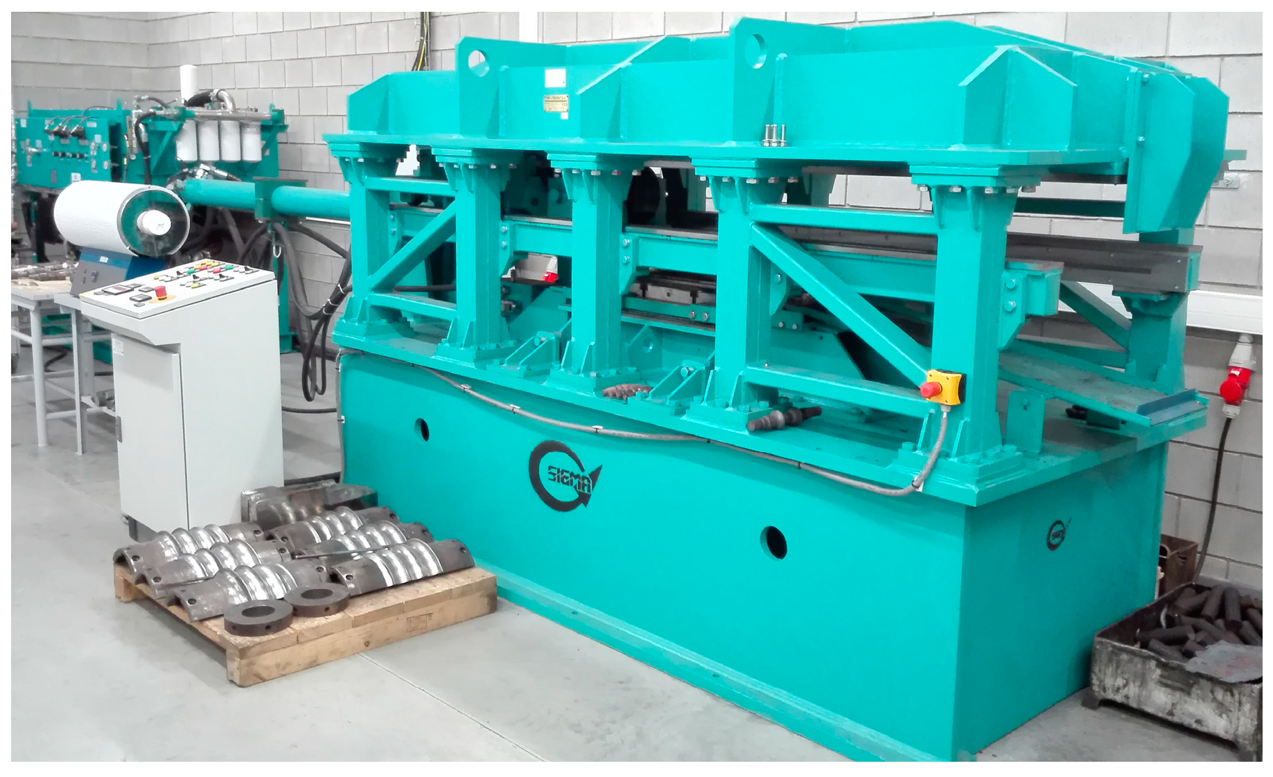
During the research of cross-rolling of steel balls, a laboratory cross-rolling mill (Sigma, Barak, Poland), shown in Figure 1, was used. The aforementioned machine operates in a circuit in which the upper tool (hydraulically driven) makes a reciprocating motion, whereas the lower tool remains static. Moreover, the machine is equipped with a measurement system that allowed for registering the pressure force of the hydraulic cylinder. The technical specifications of the cross-rolling mill are presented in Table 3.
The model tests of cross-rolling were conducted in a test stand created on the basis of a laboratory chain drawing machine CGD-E 2000 (Figure 2, Rodent, Pruszków, Poland). The test stand consists of four main sets containing a drawing machine; a module of the model rolling mill; a measuring circuit; and a computer with software allowing for importing the test result data and, further on, its processing via the Internet. The linear velocity of the chain in the laboratory drawing machine can be regulated, which allows for the regulation of the displacement of the upper tool ranging from 0 to 136 mm/s. The module of the rolling mill enables the use of flat tools of a maximum of 140 mm × 400 mm overall dimensions.
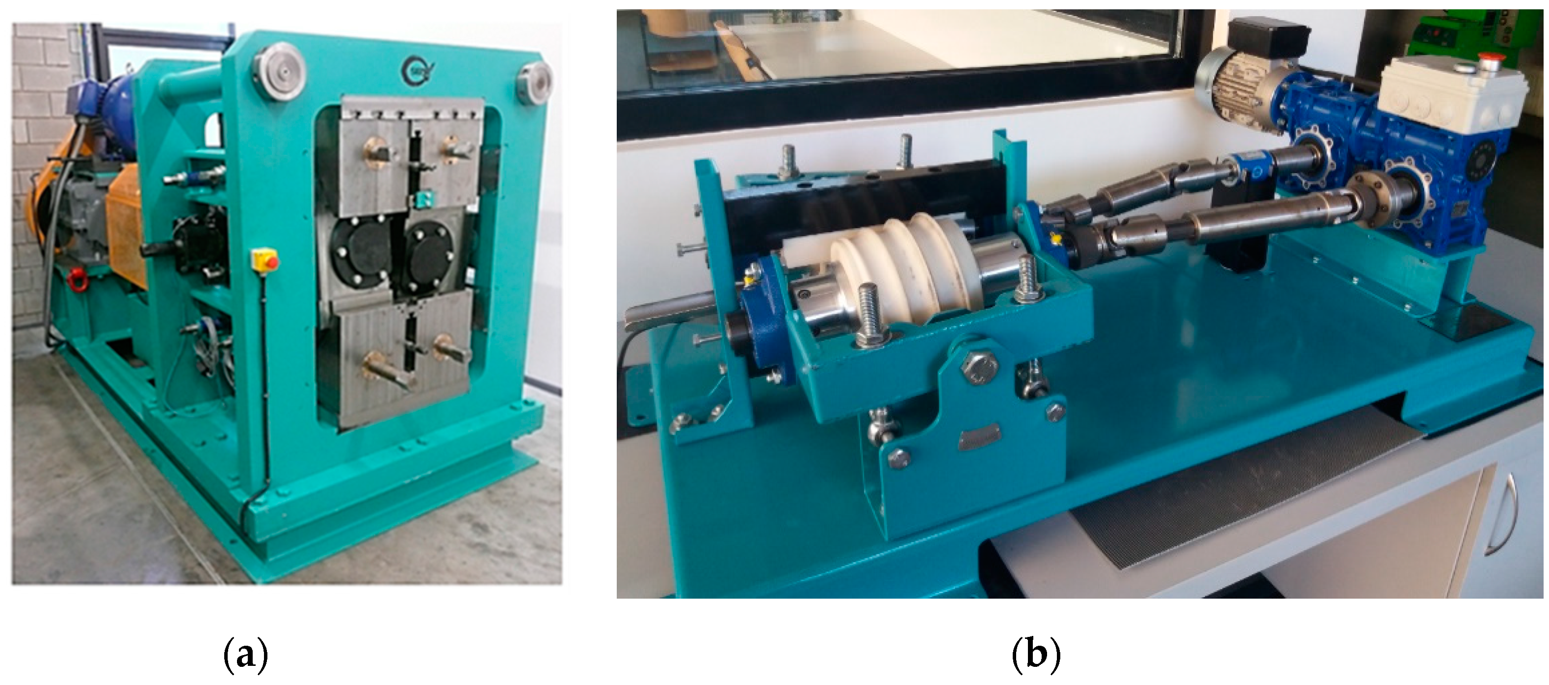
A laboratory rolling mill (Sigma, Barak, Poland) shown in Figure 3a was used in the research of helical rolling of steel balls. The rolls of the machine are driven by an electric motor through belt transmission, toothed belt transmission, and Cardan joint. The rolling mill is equipped with a circuit measuring the torque and the pressure force on the roll. The data specifications of this machine are shown in Table 4.
The model tests of helical rolling of balls were conducted in a model skew-rolling mill (Sigma, Barak, Poland), shown in Figure 3b. The drive unit of the machine consists of a 0.25 kW electric motor that allows for forming samples with the torque reaching 99 Nm (for each roll). The nominal rotational speed of the rolls equals 12 rpm, whereas their overall dimensions are Ø150 mm × 200 mm.
4. Tools for Rolling Steel Balls
Cross rolling of 40 mm diameter balls was performed using two tools, which enabled even forming of six balls. One of these tools is shown schematically in Figure 4. In the tool, two zones can be distinguished; namely forming (635 mm long) and sizing (300 mm long). In the forming zone, the billet of the initial dimensions Ø36 mm × 220 mm is divided into parts, the volume of which equals the volume of the formed balls. Apart from being divided, the balls in the forming zone are compressed as well, which allows for reaching the assumed diameter. In the sizing zone, the previously formed balls are rolling in impressions inclined from the rolling direction by 2.5° to 3.5°. The inflection of the impressions forces the ball rotation axis to change and thus helps to remove the remainder of the connectors between balls.
Figure 5a shows the tools used for forming steel balls, manufactured in a Computerized Numerical Control (CNC) machine (Feeler, Taichung, Taiwan) and heat treated to 44–46 HRC hardness according Rockwell (Innovatest, Wiry, Poland). The tools were manufactured from hot work tool steel. Additionally, Figure 5b shows 1:2.5 scale model tools, 3D printed from ABS.
In the process of rolling 57 mm diameter steel balls, two identical helical rolls were used. Figure 6 schematically shows one of these rolls. Each roll has a helically wound wedge defined by the side wall’s angle of inclination equal to 45°. The wedge cyclically (once each turn) cuts into the billet, closing the volume of the material equal to the volume of the formed ball in the impression. As a result of the impact of the collar, the height of which gradually increases, the ball is separated from the billet. In the final phase of the process, the ball is sized in the impression in order to remove the occurring shape deviations.
Figure 7 shows one of the helical tools, manufactured using the CNC method and heat treated to 44–46 HRC hardness. The tool consists of three parts fixed with screws to the roll in the rolling mill. A key joint is used to distribute the drive from the roll to the working segment. One of two guiding devices was placed next to the elements of the rolling mill. The aim of the guiding device was to keep the material in the working segment during the rolling process. In the case of the 1:2 scale model made of ABS, the rolls were divided into two parts. These elements were fixed with screws to the aluminum shafts.
5. Test Results
Cross rolling of 40 mm diameter balls was performed using Ø36 mm × 220 mm C45 grade steel billets. These billets were heated up to 1000 °C in an electric chamber furnace and placed on a lower, motionless/static tool. After putting the upper tool in motion, the material rolled on the lower tool and formed balls rolled down to the container (Figure 8).
In the case of cross-rolling of the 1:2:5 scale model plasticine balls, the dimensions of the billet were equal to Ø14.5 mm × 90 mm. The method of manufacturing aforementioned billets was that of direct extrusion. They were also cooled for 24 h at 5 °C prior to rolling. The model rolling process was conducted similarly to the real process. It was assumed that the displacement speed of the upper tool was 122 mm/s (in the process of forming steel balls, the displacement speed was equal to 300 mm/s). The tools were lubricated with teflon oil.
The balls manufactured in the process of cross-rolling are presented in Figure 9. An analysis of the shape of balls showed that the side balls contain a ring-shaped underfill, most likely the result of excessive material flow into side waste. This defect occurs in both steel and plasticine balls. Moreover, the remainders of the connectors could be noticed in some of the steel balls. This defect occurred most frequently in balls made of black plasticine.
As far as the manufacturing accuracy is concerned, it is to be stated that the diameter of the steel balls was Ø39.7 mm ± 0.6 mm, that of the balls made of white plasticine was Ø16.4 mm ± 0.4 mm, and that of the balls made of black plasticine was Ø16.3 mm ± 0.3 mm. As the producing tolerance for grinding medium equals ±3 mm, it is to be noted that the steel balls manufactured using the cross-rolling technique meet this requirement and can thus be manufactured in such a way. A comparison of the shapes and dimensions of steel and plasticine balls shows a high level of compliance and validates the use of physical modelling in the analysis of the cross-rolling process.
During the process of cross-rolling, the displacement force of the upper tool was registered. The attained parameters are presented in Figure 10. An analysis of these parameters shows that in terms of quality, the force parameters concerning the forming of white and black plasticine balls are identical, although the forces required to deform black plasticine are higher. The force parameters for C45 grade steel, however, differ somewhat from the ones registered in the model testing. During the rolling of the steel balls, the force increases faster in the forming zone, which can partially be justified by the cooling of the material. This process leads to the increase in flow stress. The opposite effect can be noticed in model rolling (the temperature of plasticine increases and the flow stress decreases). Further on, the force reaches its maximal value in the moment of balls separation and decreases drastically only to maintain the decreasing (for the model material) or increasing (for steel) trend in the sizing zone. The reason for such a discrepancy is most likely the aforementioned temperature difference of the formed material.
For a quantitative comparison, maximum force, Fmax, was chosen. As far as rolling of steel balls from a 1000 °C billet is concerned, the maximum force equaled 94.37 kN. In order to estimate the Fmax value, the following relation was applied on the basis of a physical simulation:
where λ—the similarity factor of model material and C45 grade steel flow stress; F’max—maximum force from the model tests, N; s—scale of tools.
In order to determine the similarity factor λ between plasticine and C45 grade steel at 1000 °C, the following relation was applied:
where to calculate the flow stress, Equations (1) and (2) were applied. The obtained results are shown in Table 5.
The obtained results remain highly compliant with the value of maximum force registered in the real process. Higher compliance, however, was achieved for black plasticine. In this case, force overestimation equaled 2%, whereas the underestimation of force for white plasticine reached 9.4%. Thus, it is to be stated that physical modelling with plasticine as the model material can prove helpful in estimating the forces occurring in the process of cross rolling.
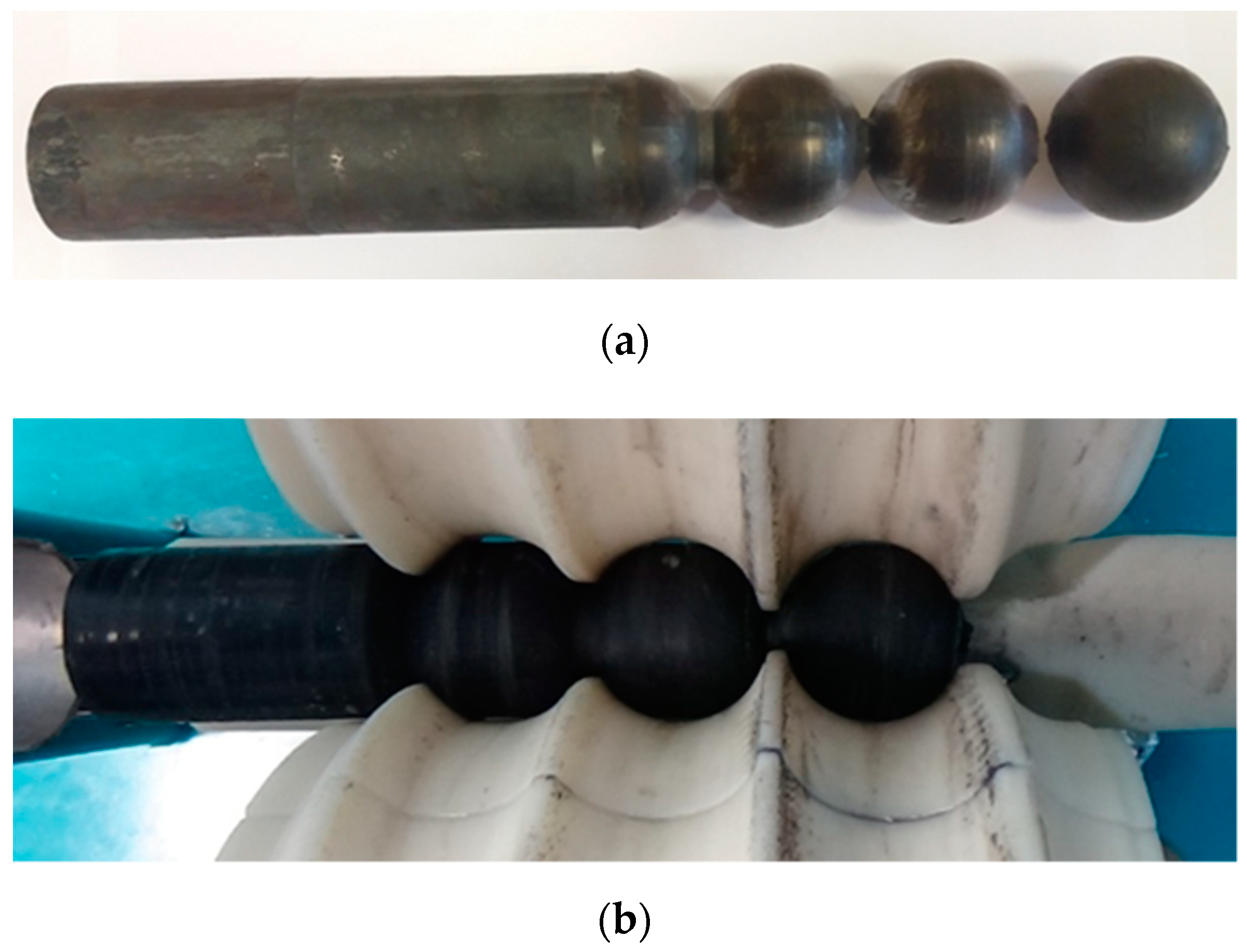
In the case of helical rolling, Ø57 mm diameter balls were formed using C60 steel grade, Ø55 mm × 600 mm billets. This time, the material was heated to 1050 °C and the rolls were inclined at the angle of 4° in relation to the centerline of the billet. During the rolling process, the tool was cutting into the billet (once each turn) and creating a narrowing of a gradually increasing depth. Such forming caused the material to lose its structural integrity and thus resulted in separation of balls, presented in Figure 11. In the final phase of the process, the ball was sized and rotated around various axes.
The process of helical rolling of the 1:2 scale model material was similar to the real process. The only difference was lubricating the surface of the tools with teflon oil before rolling. The process of manufacturing the Ø27.5 mm × 200 mm billets was similar to the previously described process of cross rolling.
Figure 12 shows the helically rolled balls manufactured both from the model material and C60 steel grade. The shape of the balls was perfect and they were essentially free of surface defects. On the basis of the measurements taken, it was stated that the diameter of steel balls and balls made of the model material was equal to Ø57.4 mm ± 0.5 mm and Ø28.4 mm ± 0.3 mm, respectively. The obtained manufacturing accuracy meets the requirements of the balls for mills.
During helical rolling of balls, the torque of one roll was registered. The obtained parameters for the model material are presented in Figure 13a, whereas those for C60 grade steel are shown in Figure 13b. The analysis of these parameters showed a high level of compliance. In all of the cases, the torque changed cyclically, which was caused by the periodical (once each turn) cutting of the tools into the formed material.
For a quantitative comparison, the maximum torque was selected. For C60 grade steel balls of Ø57 mm diameter, the torque was equal to Mmax = 7076 Nm (Figure 13b). In order to estimate the Mmax value, the following equation was applied:
where M′max—maximum torque during the rolling of the model material, Nm; λ and s—as in Equation (5), respectively.
The similarity factor λ was calculated on the basis of the relation (6), assuming that the flow stress σF is defined by Equations (1), (2) and (4). The scale of the tools s was assumed to be 2. Because the shaping of steel balls was a rather long process (over 25 s), the estimations were made for two temperatures, namely 1050 °C (temperature of the billet) and 1000 °C (assumes the 50 °C drop in the temperature during the rolling). The results of the calculations are presented in Table 6.
The comparison of the Mmax values obtained in the process of rolling steel balls (7076 Nm) and the estimations based on the model tests (Table 6) shows a high compliance. Better results, however, were achieved for black plasticine. In this case, the moment value of the real process lay within the range defined by the calculations made for 1050 °C and 1000 °C temperatures. Thus, the validity of determining the torque in the process of rolling steel balls based on the model tests using plasticine was confirmed.
6. Conclusions
On the basis of the tests conducted, the following conclusions were drawn:
- Using plasticine as the model material allows for effective research on the kinematics of material flow in the processes of cross rolling and helical rolling of balls, as well as to extrapolate the manufacturing accuracy of the product.
- An indubitable advantage of physical modelling (compared with FEM-based numerical analysis) is the accuracy of illustrating the moment of material division that occurs in the process of ball rolling.
- Basing on the test results allows for a highly accurate extrapolation of the following force parameters in the ball rolling process: forming force or the torque of the roll.
- Plasticine-based physical modelling can prove beneficial in analyses of cross rolling and helical rolling of balls, and may thus be used to optimize their manufacturing techniques.
Author Contributions
The research was conceived by Z.P., J.T., Ł.W. and T.B. The methodology was planned by Z.P. and J.T. Experimental tests of steel rolling were performed by J.T. and T.B. Experimental tests of plasticine rolling was performed by Ł.W. The manuscript was written by Z.P. with support from T.B.
Funding
This research received no external funding.
Conflicts of Interest
The authors declare no conflict of interest.
References
- Wang, Q.X.; Wang, Q.P.; Xiao, J.M. Study on the method for groove design in the helical rolling of steel balls. J. Mater. Process. Technol. 1995, 55, 340–344. [Google Scholar] [CrossRef]
- Yang, S.C.; Chen, C.K. The surface geometry of rollers with skew rolling of steel balls. J. Mech. Eng. Sci. 2001, 215, 523–532. [Google Scholar] [CrossRef]
- Pater, Z. Multi-wedge cross rolling of balls. J. Iron Steel Res. Int. 2013, 20, 46–50. [Google Scholar] [CrossRef]
- Pater, Z.; Tomczak, J.; Bartnicki, J.; Lovell, M.R.; Menezes, P.L. Experimental and numerical analysis of helical-wedge rolling process for producing steel balls. Int. J. Mach. Tool Manuf. 2013, 67, 1–7. [Google Scholar] [CrossRef]
- Cao, Q.; Hua, L.; Qian, D. Finite element analysis of deformation characteristics in cold helical rolling of bearing steel-balls. J. Cent. South Univ. 2015, 22, 1175–1183. [Google Scholar] [CrossRef]
- Pater, Z.; Tomczak, J.; Bulzak, T. A cross wedge rolling process for forming 70 mm diameter balls from heads of scrap railway rails. Proc. Manuf. 2017, 11, 466–473. [Google Scholar] [CrossRef]
- Chijiwa, K.; Hatamura, Y.; Hasegawa, N. Characteristics of plasticine used in the simulation of slab in rolling and continuous casting. Trans. Iron Steel Inst. Jpn. 1981, 21, 178–186. [Google Scholar] [CrossRef]
- Kawasaki Steel Technical Report. Available online: www.jfe-steel.co.jp/archives/en/ksc_giho/no.01/tobira033.html (accessed on 22 October 2018).
- Chijiwa, K.; Hatamura, Y.; Suzuki, T. Experimental method of stress simulation of rolling and continuously cast slab by plasticine. Trans. Iron Steel Inst. Jpn. 1981, 21, 502–511. [Google Scholar] [CrossRef]
- Yazawa, T.; Tanaka, T.; Noda, A.; Morita, T.; Takeda, R.; Hayashi, H. Development of grooveless rolling. Trans. Iron Steel Inst. Jpn. 1983, 23, 710–715. [Google Scholar] [CrossRef]
- Chijiwa, K.; Hatamura, Y.; Hasegawa, N.; Tanabe, Y. Simulation of horizontal 2-stands rolling by plasticine. Trans. Iron Steel Inst. Jpn. 1984, 24, 292–300. [Google Scholar] [CrossRef]
- Segawa, A.; Kawanami, T. Rolling-deformation characteristics of clad materials determined by model experiments and numerical simulations: Numerical simulation of clad rolling by rigid-plastic FEM. J. Mater. Process. Technol. 1995, 53, 544–551. [Google Scholar] [CrossRef]
- Takemasu, T.; Vazquez, V.; Painter, B.; Altan, T. Investigation of metal flow and preform optimization in flashless forging of connecting rod. J. Mater. Process. Technol. 1996, 59, 95–105. [Google Scholar] [CrossRef]
- Dutta, A.; Rao, A. Simulation of isothermal forging of compressor disc by combined numerical and physical modelling techniques. J. Mater. Process. Technol. 1997, 72, 392–395. [Google Scholar] [CrossRef]
- Miñano, M.; Caminero, M.A.; Montáns, F.J. On the numerical implementation of the Closest Point Projection algorithm in anisotropic elasto-plasticity with nonlinear mixed hardening. Finite Elem. Anal. Des. 2016, 121, 1–17. [Google Scholar] [CrossRef]
- Vazquez, V.; Altan, T. New concepts in die design–physical and computer modelling applications. J. Mater. Process. Technol. 2000, 98, 212–223. [Google Scholar] [CrossRef]
- Fujikawa, S. Application of CAE for hot-forging of automotive components. J. Mater. Process. Technol. 2000, 98, 176–181. [Google Scholar] [CrossRef]
- Park, J.H.; Kim, Y.H.; Jin, Y.E. Experimental investigation of the forming parameters of the rotational upset forging process. J. Mater. Process. Technol. 2001, 111, 103–106. [Google Scholar] [CrossRef]
- Zhan, M.; Liu, Y.; Yang, H. Physical modelling of the forging of a blade with a damper platform using plasticine. J. Mater. Process. Technol. 2001, 117, 62–65. [Google Scholar] [CrossRef]
- Yang, D.Y.; Ahn, D.G.; Lee, C.H.; Park, C.H.; Kim, T.J. Integration of CAD/CAM/CAE/RP for the development of metal forming process. J. Mater. Process. Technol. 2002, 125–126, 26–34. [Google Scholar] [CrossRef]
- Fereshteh-Saniee, F.; Hosseni, A.H. The effects of flash allowance and bar size on forming load and metal flow in closed die forging. J. Mater. Process. Technol. 2006, 177, 261–265. [Google Scholar] [CrossRef]
- Buteler, D.I.; Neves, P.C.U.; Ramos, L.V.; Santos, C.E.R.; Souza, R.M.; Sinatora, A. Effect of anvil geometry on the stretching of cylinders. J. Mater. Process Technol. 2006, 179, 50–55. [Google Scholar] [CrossRef]
- Hosseini-Ara, R.; Yavari, P. A new criterion for preform design of H-shaped hot die forging based on shape complexity factor. Int. J. Mater. Form. 2018, 11, 233–238. [Google Scholar] [CrossRef]
- Kim, Y.H.; Park, J.H. Upper bound analysis of torsional backward extrusion process. J. Mater. Process. Technol. 2003, 143–144, 735–740. [Google Scholar] [CrossRef]
- Kazanowski, P.; Epler, M.E.; Misiolek, W.Z. Bi-metal rod extrusion–process and product optimization. Mater. Sci. Eng. 2004, 369, 170–180. [Google Scholar] [CrossRef]
- Sofuoglu, H.; Gedikli, H. Physical and numerical analysis of three dimensional extrusion process. Comp. Mater. Sci. 2004, 31, 113–124. [Google Scholar] [CrossRef]
- Zhou, W.; Lin, J.; Dean, T.A.; Wang, L. Analysis and modelling of a novel process for extruding curved metal alloy profiles. Int. J. Mech. Sci. 2018, 138–139, 524–536. [Google Scholar] [CrossRef]
- Shih, C.K.; Hung, C. Experimental and numerical analyses on three-roll planetary rolling process. J. Mater. Process Technol. 2003, 142, 702–709. [Google Scholar] [CrossRef]
- Hwang, Y.M.; Tsai, W.M.; Tsai, F.H.; Her, I. Analytical and experimental study on the spiral marks of the rolled product during three-roll planetary rolling processes. Int. J. Mach. Tool Manuf. 2006, 46, 1555–1562. [Google Scholar] [CrossRef]
- Stanistreet, T.F.; Allwood, J.M.; Willoughby, A.M. The design of a flexible model ring rolling machine. J. Mater. Process Technol. 2006, 177, 630–633. [Google Scholar] [CrossRef]
- Jeon, C.H.; Han, S.W.; Joo, B.D.; Van Tyne, C.J.; Moon, Y.H. Deformation analysis for cold rolling of Al-Cu double layered sheet by physical modelling and finite element method. Met. Mater. Int. 2013, 19, 1069–1076. [Google Scholar] [CrossRef]
- Lee, S.J.; Lee, K.H.; Kim, B.M. Design of roll profile for complex shape in shape rolling by combined 3D-EFA and BWT. Int. J. Precis. Eng. Manuf. 2015, 16, 281–286. [Google Scholar] [CrossRef]
- Wójcik, Ł.; Pater, Z. Physical analysis of cross-wedge rolling process of a stepped shaft. Adv. Sci. Technol. Res. J. 2017, 11, 60–67. [Google Scholar] [CrossRef]
- Wójcik, Ł.; Lis, K.; Pater, Z. Plastometric tests for plasticine as physical modelling material. Open Eng. 2016, 6, 653–659. [Google Scholar] [CrossRef]
- Wójcik, Ł.; Pater, Z. Limiting value of Cockroft-Latham integral for commercial plasticine. Appl. Comp. Sci. 2017, 13, 45–55. [Google Scholar] [CrossRef]
- Pater, Z. Cross-Wedge Rolling. In Comprehensive Materials Processing, 1st ed.; Hashmi, S., Van Tyne, C.J., Batalha, G.F., Yilbas, B., Eds.; Elsevier Ltd.: Amsterdam, The Netherlands, 2014; Volume 3, pp. 211–279. [Google Scholar]
Figure 1.
Laboratory stand for cross rolling—flat wedge rolling mill.

Figure 2.
Laboratory stand for cross rolling of model material with an emphasized rolling module.

Figure 3.
Laboratory stand for helical rolling of (a) real material—steel; (b) model material—plasticine.
Figure 3.
Laboratory stand for helical rolling of (a) real material—steel; (b) model material—plasticine.

Figure 4.
Flat tool for cross rolling of Ø40 mm diameter balls, with the chosen dimensions in mm given.
Figure 4.
Flat tool for cross rolling of Ø40 mm diameter balls, with the chosen dimensions in mm given.

Figure 5.
Flat tools for forming of six balls: (a) 40 mm diameter steel balls; (b) 1:2.5 scale model tools for plasticine balls.
Figure 5.
Flat tools for forming of six balls: (a) 40 mm diameter steel balls; (b) 1:2.5 scale model tools for plasticine balls.

Figure 6.
Helical roll for rolling Ø57 mm diameter balls, with the selected dimensions in mm given.

Figure 7.
Tools for helical rolling of (a) 57 mm diameter steel balls; (b) 1:2 scale model tools for plasticine balls.
Figure 7.
Tools for helical rolling of (a) 57 mm diameter steel balls; (b) 1:2 scale model tools for plasticine balls.

Figure 8.
Cross rolling of six balls in (a) the model rolling mill; (b) a flat wedge rolling mill.

Figure 9.
Balls manufactured during the research from (from the top to bottom) white plasticine (a), black plasticine (b), and C45 grade steel (c).
Figure 9.
Balls manufactured during the research from (from the top to bottom) white plasticine (a), black plasticine (b), and C45 grade steel (c).

Figure 10.
Distribution of the force moving the wedge tool, registered during cross rolling of balls.
Figure 10.
Distribution of the force moving the wedge tool, registered during cross rolling of balls.

Figure 11.
The rolled item seen during helical rolling of steel (a) and plasticine balls (b).

Figure 12.
Helically rolled balls of (a) plasticine with Ø28.5 mm diameter; (b) steel with Ø57 mm diameter.
Figure 12.
Helically rolled balls of (a) plasticine with Ø28.5 mm diameter; (b) steel with Ø57 mm diameter.

Figure 13.
Torque of the roll registered during (a) helical rolling of balls from model material; (b) helical rolling of C60 grade steel balls of 57 mm diameter.
Figure 13.
Torque of the roll registered during (a) helical rolling of balls from model material; (b) helical rolling of C60 grade steel balls of 57 mm diameter.


Table 1.
Constant of the white and black plasticine material models.
| Material | C | n1 | n2 | m | b | a |
|---|---|---|---|---|---|---|
| White plasticine | 0.48057 | −0.0313 | 0.08705 | 0.2451 | −0.0026 | −0.03283 |
| Black plasticine | 0.6817 | −0.0711 | 0.07203 | 0.2701 | −0.0037 | −0.07358 |
Table 2.
Constant of the C45 and C60 grade steel material models.
| Material | C1 | C2 | n1 | n2 | I1 | I2 | m1 | m2 |
|---|---|---|---|---|---|---|---|---|
| C45 | 4105 | −0.00354 | −0.00013 | −0.0051 | −0.000023 | −0.0281 | 0.00018 | −0.0241 |
| C60 | 4857 | −0.00374 | −0.00022 | 0.07908 | −0.000026 | −0.0149 | 0.00016 | −0.00965 |
Table 3.
Technical specification of the cross rolling mill located in the Lublin University of Technology.
Table 3.
Technical specification of the cross rolling mill located in the Lublin University of Technology.
| Parameter | Value |
|---|---|
| Speed of the main cylinder’s piston | 300 mm/s |
| Nominal force of the piston’s pressure | 105 kN |
| Working stroke of the main cylinder | 2000 mm |
| Engine power of the main drive | 55 kW |
| Maximum diameter of the rolled product | Ø70 mm |
| Maximum length of the rolled product | 320 mm |
| Dimensions: length × width × height | 6000 mm × 1350 mm × 2000 mm |
| Weight of the machine without the hydraulic power unit | 10,500 kg |
Table 4.
Technical specification of the skew rolling mill located in the Lublin University of Technology.
Table 4.
Technical specification of the skew rolling mill located in the Lublin University of Technology.
| Parameter | Value |
|---|---|
| Nominal diameter of rolls | 300 mm |
| Working length of roll barrel | 400 mm |
| Distance between roll axes: maximum/minimum | 350 mm/300 mm |
| Rotational speed of rolls | 30/15 rpm |
| Engine power of the main drive | 60/80 kW |
| Dimensions: length × width × height | 3200 mm × 1800 mm × 2100 mm |
| Weight of the machine | 17,500 kg |
Table 5.
Extrapolation of the maximum forces occurring in cross rolling of 40 mm diameter balls, based on the test results of the model process.
Table 5.
Extrapolation of the maximum forces occurring in cross rolling of 40 mm diameter balls, based on the test results of the model process.
| Materials | λ | s | F’max | Fmax |
|---|---|---|---|---|
| White plasticine | 215.7 | 2.5 | 63.44 N | 85.52 kN |
| Black plasticine | 171.8 | 2.5 | 89.66 N | 96.27 kN |
Table 6.
Extrapolation of the maximum moments in helical rolling of 57 mm diameter balls, based on test results of the model process.
Table 6.
Extrapolation of the maximum moments in helical rolling of 57 mm diameter balls, based on test results of the model process.
| Materials | T | λ | s | M′max | Mmax |
|---|---|---|---|---|---|
| White plasticine | 1050 °C | 180.18 | 2 | 3.80 Nm | 5477 Nm |
| 1000 °C | 212.24 | 2 | 3.68 Nm | 6452 Nm | |
| Black plasticine | 1050 °C | 143.48 | 2 | 5.53 Nm | 6347 Nm |
| 1000 °C | 169.01 | 2 | 5.53 Nm | 7477 Nm |
© 2019 by the authors. Licensee MDPI, Basel, Switzerland. This article is an open access article distributed under the terms and conditions of the Creative Commons Attribution (CC BY) license (http://creativecommons.org/licenses/by/4.0/).
Share and Cite
MDPI and ACS Style
Pater, Z.; Tomczak, J.; Wójcik, Ł.; Bulzak, T. Physical Modelling of the Ball-Rolling Processes. Metals 2019, 9, 35. https://doi.org/10.3390/met9010035
AMA Style
Pater Z, Tomczak J, Wójcik Ł, Bulzak T. Physical Modelling of the Ball-Rolling Processes. Metals. 2019; 9(1):35. https://doi.org/10.3390/met9010035
Chicago/Turabian StylePater, Zbigniew, Janusz Tomczak, Łukasz Wójcik, and Tomasz Bulzak. 2019. "Physical Modelling of the Ball-Rolling Processes" Metals 9, no. 1: 35. https://doi.org/10.3390/met9010035
Note that from the first issue of 2016, this journal uses article numbers instead of page numbers. See further details here.