Measurement of Molten Steel Velocity near the Surface and Modeling for Transient Fluid Flow in the Continuous Casting Mold


State Key Laboratory of Advanced Special Steel, Shanghai University, Shanghai 200444, China
*
Author to whom correspondence should be addressed.
Metals 2019, 9(1), 36; https://doi.org/10.3390/met9010036
Submission received: 11 December 2018
/
Revised: 23 December 2018
/
Accepted: 29 December 2018
/
Published: 4 January 2019
(This article belongs to the Special Issue Ironmaking and Steelmaking)
Abstract
:In the current work, a rod deflection method (RDM) is conducted to measure the velocity of molten steel near the surface in continuous casting (CC) mold. With the experimental measurement, the flow velocity and direction of molten steel can be obtained. In addition, a mathematical model combining the computational fluid dynamics (CFD) and discrete phase method (DPM) has been developed to calculate the transient flow field in a CC mold. The simulation results are compared and validated with the plant measurement results. Reasonable agreements between the measured and simulated results are obtained, both in the trends and magnitudes for the flow velocities of molten steel near the mold surface. Based on the measured and calculated results, the velocity of molten steel near the surface in the mold increases with increasing casting speed and the casting speed can change the flow pattern in the mold. Furthermore, three different types of flow patterns of molten steel in the mold can be obtained. The pattern A is the single-roll-flow (SRF) and the pattern C is the double-roll-flow (DRF). The pattern B is a transition state between DRF and SRF, which is neither cause the vortices nor excessive surface velocity on the meniscus, so the slag entrainment rarely occurs. Argon gas injection can slow down the molten steel velocity and uplift the jet zone, due to the buoyancy of bubbles. Combination of the measurement and numerical simulation is an effective tool to investigate the transient flow behavior in the CC mold and optimize the actual operation parameters of continuous casting to avoid the surface defects of the automobile outer panels.
1. Introduction
The surface defects on the cold rolled sheets for automobile outer panels related to the steelmaking process are mainly the large-sized Al2O3 clusters, “Ar + Al2O3” typed inclusions and the entrapped mold powder particles [1]. Generally, the non-metallic inclusions and the entrapped mold powder particles produced in the steelmaking and continuous casting (CC) process are firstly crushed down and then elongated along the rolling direction during the subsequent rolling process. Finally, they are discretely distributed along the rolling direction to form the line-shape defects, such as sliver, scab and blister.
Yasunaka H. [2] studied the surface defects in ULC steel and found that the defects were caused by the capture of argon bubbles whose diameter are 0.5–3 mm into the solidification structure ‘hook.’ Yang J. [3] researched the morphologies and chemical compositions for three kinds of surface defects on automobile outer panels and found that the stripe widths and lengths formed by three kinds of defects are different. Wang X.H. [4,5] studied the defects of IF steel in continuous casting slab and found that in the bottom slab of the cast, the number of inclusions from the mold powder entrapment is much more than that in the normal casting slabs. The number density of the large inclusions decreases with increasing casting speed when the casting speed is 1.0–2.0 m/min.
The formation of surface defects on cold rolled sheets is closely related to the flow behavior in the CC mold. Therefore, it is very important to investigate the flow field and flow pattern in the mold. The simulated calculation is an important means to research the flow behavior of molten steel in the CC mold. The transient flow field and the velocity near the surface in CC mold were investigated in many previous works [6,7,8,9,10]. The most popular numerical approach is the Reynolds time-averaged (RANS) model to predict steady-state and single-phase flow [11,12,13,14]. Liu C.L. [15] used a Eulerian-Lagrangian two-way coupled model to explore transient argon-steel system flow patterns in the mold. Wang Y.F. [16,17] investigated the complicated phenomena which are associated with transient stages during the continuous casting process using the Unsteady RANS model. They found that the acceleration rate for casting speed significantly affected the magnitude of velocity in the mold. In recent years, as the computer became more powerful than ever, the Large Eddy Simulation (LES) has been popular to investigate the transient flow and particles behavior in the CC mold [18,19,20,21,22].
The velocity of molten steel near the surface is one of the flow parameters which can be measured to predict the flow field and flow pattern in the CC mold. In many previous works, the water model experiments have been carried out to measure the flow velocity near the surface and investigate the flow field and flow pattern in the mold. Miki Y. [23] used a propeller-type velocity meter to measure the flow velocity at the 1/4 width position on the center plane of the thickness. The results showed that the fluctuations included a wide range of flow velocities as large as 0–0.6 m/s and the period of these fluctuations was estimated to be around 15 s based on the water model experiments. In Chaudhary R.’s study [24], the impeller velocity probes positioned below the top surface on both sides of the submerged entry nozzle (SEN) were used to investigate the horizontal velocity near the surface and instantaneous velocity data were collected at a sampling frequency of 1 Hz. The transient flow phenomena and the flow velocity near the surface in the water model of continuous casting process were also studied by use of the particle image velocity (PIV) technology [25,26,27,28].
However, the multi-phase flow behavior and related phenomena in the air-water system are quite different from that in the argon-molten steel system. Therefore, it is highly desirable to measure the velocity of molten steel directly and study the flow behavior of the molten steel in the CC mold. Up to now, the mainly reported method to measure the molten steel velocity near the mold surface is nail dipping method [29,30,31]. In this method, nails are inserted into the molten steel and a lump forms on the bottom of nails. Based on the lump shape and height difference between the two sides, the velocity near the surface and direction of flow can be measured in the mold. However, not only molten steel but also the molten layer of mold powder can form a lump on nails. The viscosity of the mold powder is about ten times higher than that of molten steel, which makes the flow behavior in the molten slag completely different from that in the molten steel. Therefore, the measurement error of molten steel velocity with the nail dipping method is obviously quite large. Several works about the dipped-in rod method were reported to measure the velocity near the surface [29,30,32,33]. But the information on how to build the relationship between the deflecting angle with the velocity near the surface and other technical details was not mentioned. As a consequence, it is of great significance to study an effective method to measure the velocity of molten steel near the surface in the CC mold.
In current work, a rod deflection method (RDM) is investigated to directly measure the flow velocity of molten steel near the surface in CC mold. In addition, a mathematical model combining the computational fluid dynamics (CFD) and discrete phase method (DPM) has been developed to calculate the transient flow behavior in the CC mold. The simulation results are compared and validated with the industrial experimental measurement results. Specifically, this work aims to investigate the effect of different casting speeds on the flow velocity of molten steel near the surface and the flow pattern in the CC mold from the numerical calculation and experimental measurements.
2. Experimental Apparatus and Method
Due to the high temperature up to about 1600 °C of molten steel, it is quite difficult to measure the flow velocity using the common devices and methods. Consequently, a speed measuring device and method is newly developed to measure the flow velocity of molten steel near the surface in an actual mold.
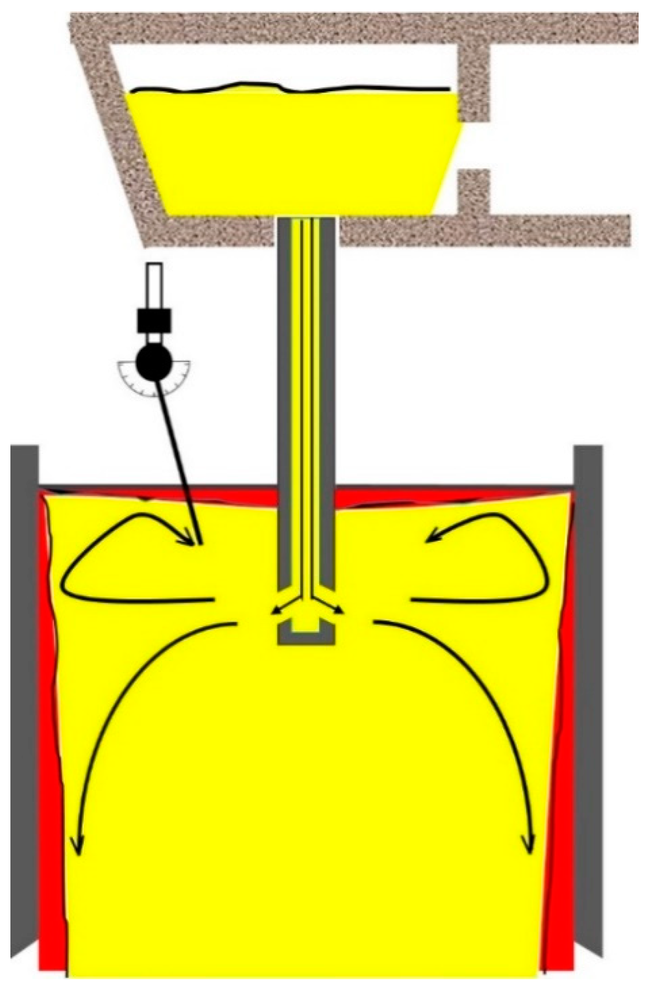
Figure 1 is the schematic diagram of the measurement method of molten steel velocity near the surface in the CC mold. The speed measuring device mainly consists of two parts: the deflecting part which can obtain the value of deflecting angle and the stainless steel detecting rod. By installing a counterweight as shown in Figure 2, the barycenter of the detecting device is adjusted to a position which is very close to the rotational pivot of the detecting rod. This design makes the detecting rod very sensitive to rotate and the accuracy of measurement can be significantly improved. Therefore, the flow direction of molten steel can be clearly known by the deflected direction and then the flow pattern in the mold can be obtained, which is helpful to control the flow behavior of molten steel in the mold. This method can be named the “Rod Deflecting Method” (RDM).
Under each experimental condition, three detection rods were used to measure the velocity of molten steel near the surface. The detecting rod can stay in the molten steel for about 30 s, the data were recorded as many as possible. More than thirty measured velocity values were obtained for each operation condition, so the average value of these velocities could minimize measuring errors caused by various reasons, such as waves, level fluctuations and large argon bubbles.
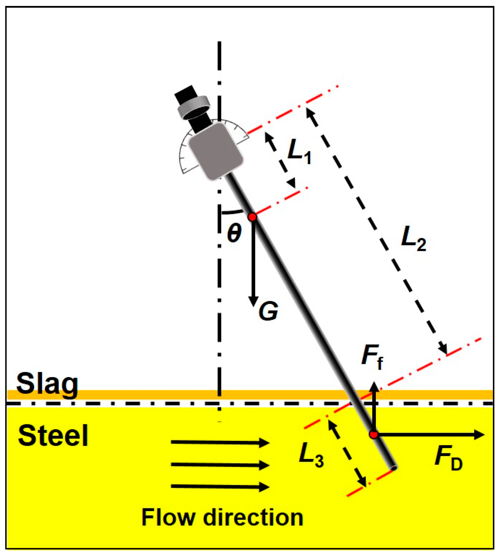
Figure 2 is the analysis of the forces acted on a detecting rod. The detecting rod is dipped into the molten steel, while the other end is supported by a pivot where the rod can freely rotate with the molten steel flow in the mold. The detecting rod is subjected to three forces: gravity (G), buoyancy force (Ff) and the impact force (FD). When the detecting rod leans to a certain angle (θ) and reaches a balanced state, the relationship of three forces can be described by the following equation:
where G is the gravity of the deflecting rod, (N); Ff is the buoyancy force of the detecting rod immersion part, (N); FD is the impact force acted on the detecting rod immersion part, (N); L1 is the distance between the barycenter of detecting rod and the rotational pivot, (m); L2 is the distance between the acting point of the impact force and the rotational pivot, (m); and θ is the rotational angle of the flow velocity detecting rod, (°).
Due to the impact force equivalent to the drag force on the detecting rod, the impact force can be expressed as the following equation:
where CD is the drag force coefficient which can be obtained from the relationship between the drag force coefficient and the Reynolds number (Re). U0 is the velocity of the steel melt, (m·s−1); ρ is the density of molten steel, (kg·m−3); A is the projection area of the detecting rod immersion part in the vertical direction of the flowing steel melt, (m2).
Equations (1) and (2) can be combined to give the following expression for calculating the velocity of the molten steel:
As shown in Equation (3), G and L1 are intrinsic parameters of the detecting rod, if the deflection angle (θ) and the immersion depth of the detecting rod (L3) are measured, the velocity of molten steel can be obtained.
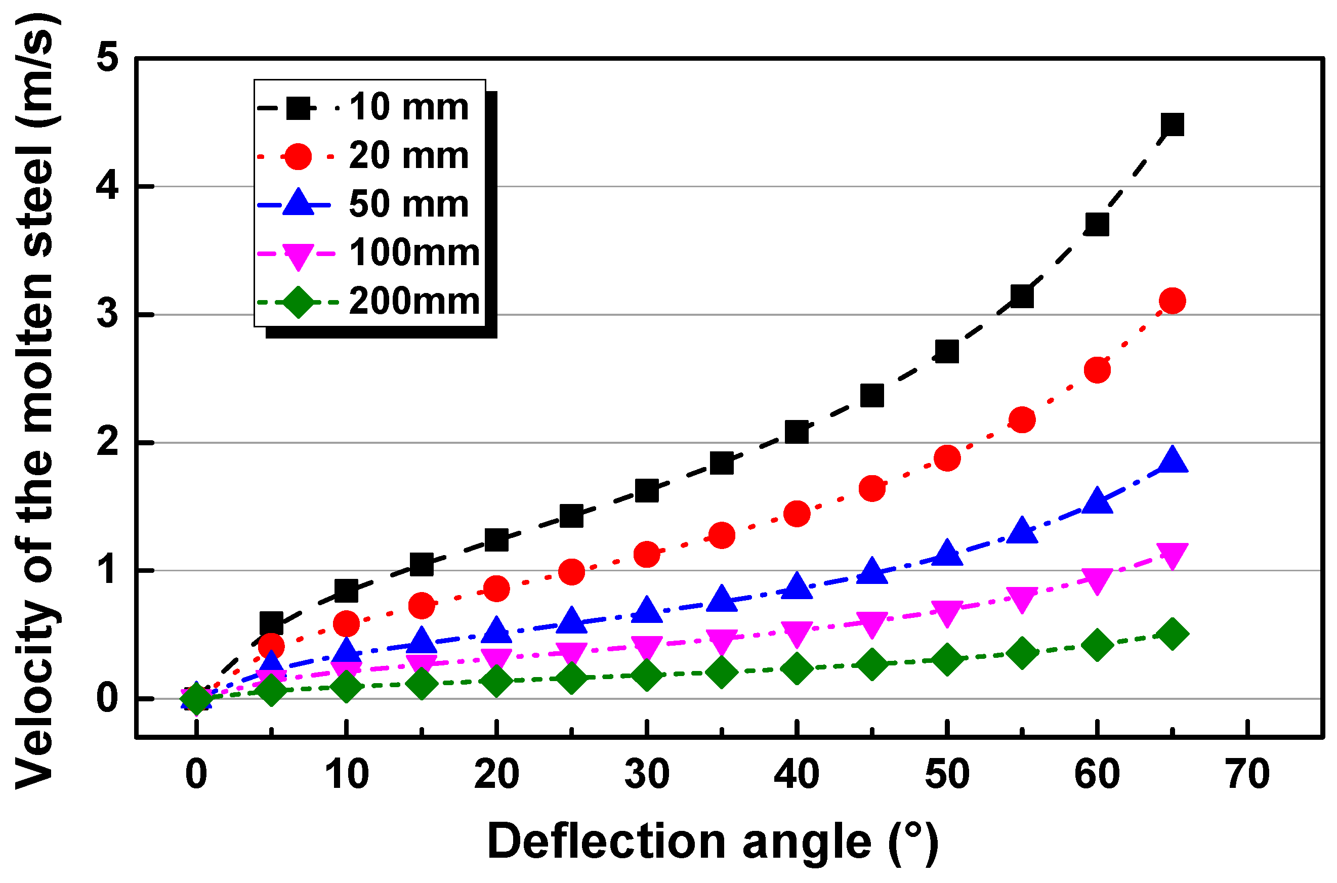
Figure 3 shows the relationship between the flow velocity of molten steel and deflection angle of detecting rod with different insertion depths. With the same insertion depth, the velocity of molten steel increases with increasing deflection angle. On the contrary, the velocity of molten steel decreases with increasing insertion depth for the same deflection angle. Thus all the experimental measurements are tried to be carried out with the same immersion depth in the present work.
3. Numerical Simulation
A numerical model is developed to simulate the turbulence flow in the SEN and CC mold, using the standard k-ε turbulent model [34], coupled with the discrete phase model (DPM) [35]. To ease the complexity of the solution process, several reasonable assumptions are applied in the present work:
- (1)
- The continuous phase is regarded as being an incompressible fluid;
- (2)
- The effect of the slag layer on the flow behavior of molten steel is ignored;
- (3)
- All bubbles are treated as the spherical shape and the effects of temperature and pressure on the bubble shape and size are ignored.
- (4)
- The deformation of the solidified shell is ignored.
- (5)
- The surface oscillations are not considered.
3.1. Fluid Flow Model
The continuity equation and momentum conservation for an incompressible fluid are given by the following equations:
where ρ is the fluid-phase density; u is the fluid-phase average velocity; p is pressure; (μl + μt) is the effective fluid-phase viscosity; F in Equation (5) is the source term for momentum exchange with the bubbles, representing the drag force, the lift force and virtual mass force respectively.
μt in Equation (5) is the turbulent viscosity, which is defined as
The standard k-ε model is used to model turbulence, which means that the following transport equations of k and ε are solved.
The values of the constants are Cμ = 0.09, σk = 1.0, σε = 1.3, C1 = 1.44, C2 = 1.92.
3.2. Discrete Phase Model
In this study, the trajectories of argon gas bubbles can be simulated using an Euler-Lagrangian approach. The transport equation for bubbles are governed by Newton’s second law and can be described as following:
The terms on the right-hand side of Equation (10) are drag force (Fd), gravitational force (Fg), buoyancy force (Ff) and other forces (Fx). Fx is an additional source term, mainly including virtual mass force (Fv), the pressure gradient force (Fp) and the lift force (FL). All forces can be expressed as follows and details can be seen in previous work [9].
where u, ub, ρ, ρb and db are the velocity of fluid, the velocity of bubbles, the density of molten steel, the density of bubbles and the diameter of bubbles, respectively. CL, Cv and Cd are the coefficients of lift force, virtual mass force and drag force, respectively.
3.3. Simulation Details
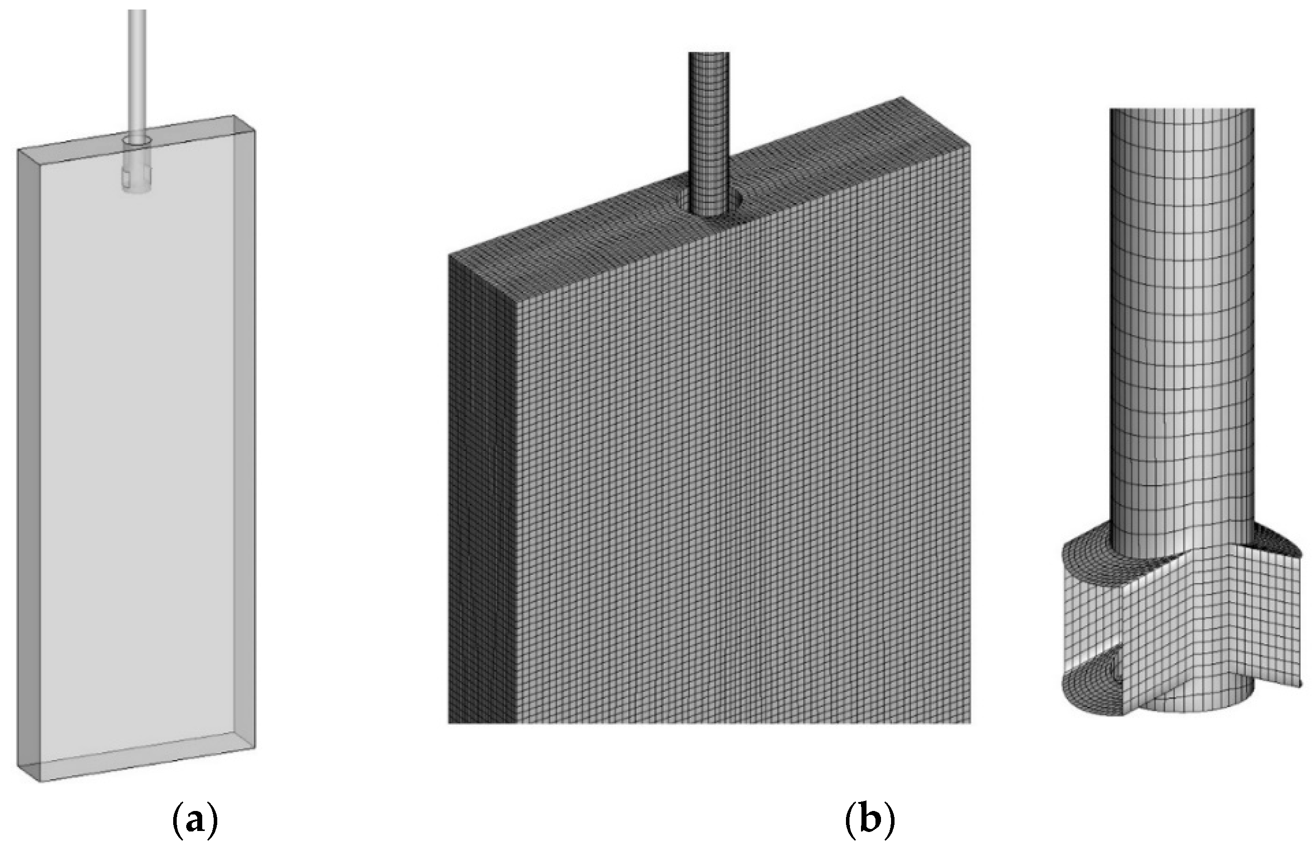
Figure 4 shows the geometry (a) and grids (b) of the computational domain. In this paper, the three-dimensional calculation area is meshed by dividing some domains to reduce the false diffusion in the process of numerical simulation. Moreover, grid refinement is applied to the submerged entry nozzle (SEN) to improve the accuracy of the simulation.
The 3D turbulence fluid flow and the trajectories of gas bubbles in a CC mold are simulated. Gas bubbles are injected from the top of the SEN and follow the flow stream through the two nozzle outlet ports into the mold. The geometrical and process parameters are given in Table 1. The whole grid consists of about 570,000 cells. The time step for the simulation is 0.001 s.
For the molten steel, the inlet boundary condition is a constant velocity at the top of the SEN and the outlet condition is outflow at the bottom of the computational domain. The top surface of the mold is assumed to have a fixed and free-slip condition. And all the walls of the mold are assumed to be stationary and no-slip.
For argon gas bubbles, it is assumed that the bubbles remain spherical and their shape variations are neglected. Based on the previous works [36], the initial bubble radius is set to be 0.5 mm as a constant value for the convenience of calculation. An escape boundary condition is defined for the top surface and outlets of the mold and the trap boundary condition is defined for the walls of the mold where bubbles are predicted to be caught. However, the reflect boundary condition is defined for the walls of SEN where bubbles are predicted to return the computational domain.
4. Results and Discussion
4.1. The Comparison between the Experimental and Calculated Results
Figure 5 shows the distribution of molten steel velocities along the mold thickness direction under the conditions of (a) without and (b) with gas injection. From the central plane to the planes near the wall of the mold along the thickness direction, the velocities of molten steel gradually decrease. Compared the distribution of velocities with and without argon gas injection, it can be found that argon gas injection can slow down the molten steel velocity and uplift the jet zone. The central planes (Z = 0) in Figure 5 are chosen to make a detailed comparison of the different distances from SEN, as shown in Figure 6.
Figure 6 shows the comparison of calculated velocity profiles at the different distances from SEN on the central plane (Z = 0). It can be seen from Figure 6 how the jets spread as they move across the mold along the width direction. The velocity profiles of the molten steel at the position of 80 mm and 270 mm away from the nozzle center have convex shapes, due to the jet zone forming out of the nozzle outlet ports. The velocities of molten steel near the nozzle are larger than those far from the nozzle. When the molten steel arrives at the narrow wall, the shape of the velocity profile becomes a concave as shown in Figure 6c, due to there is a stagnation point at the zone of impingement. The velocity of molten steel is the largest at the nozzle outlet ports and it gradually decreases towards the narrow side. Compared the red lines and black lines in Figure 6, it is seen that the velocities of molten steel with gas blowing have a difference from the condition without gas injection. The reason is that argon gas injection can greatly slow down the velocity of molten steel and uplift the jet zone, due to the buoyancy of bubbles. The similar results were reported that the gas injection widened the jet slightly and diminished its peak velocity [36].
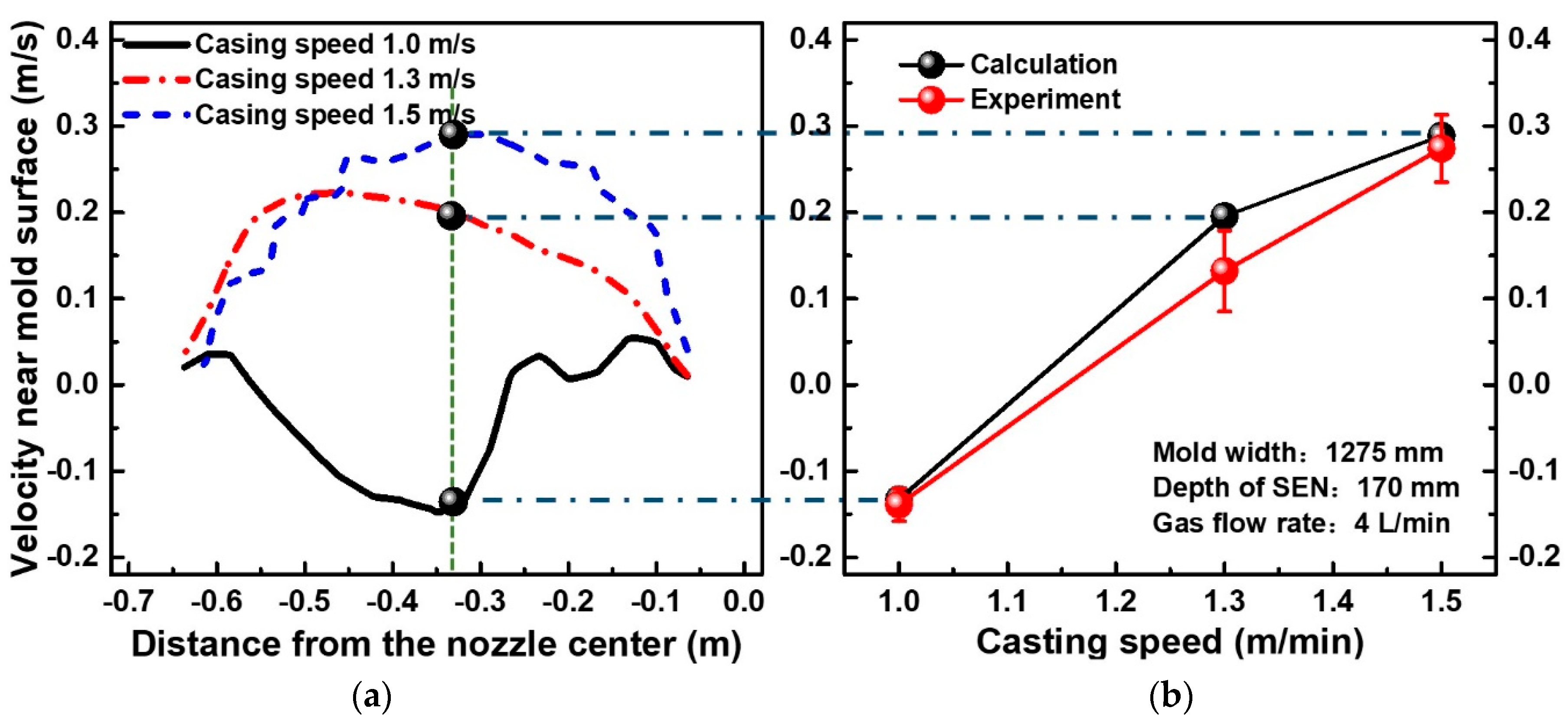
Figure 7 is the comparison of calculated and measured surface velocities with different casting speeds. Figure 7a shows the effect of different casting speeds on the molten steel velocities of 5 cm below the surface along the mold width direction on the center plane. The conditions are that the mold width is 1275 mm, the argon gas flow rate is 4 l/min and the immersion depth of SEN is 170 mm. The results show that velocities of molten steel increase with increasing casting speed, both from experimental measurement and the calculated results. The reason is that the large casting speed can increase the velocity of molten steel flowing out of the nozzle outlet ports and decrease the bubble size. On the one hand, the molten steel flowing out from the nozzle outlet ports has a large velocity to reach the narrow wall where the jet splits to flow upward and downward. On the other hand, the increased casting speed produces greater shear stress breaking large bubbles into smaller ones, which can reduce the effect of buoyancy of bubbles on slowing down the molten steel velocity and uplifting the jet zone [37]. When the casting speed is 1.0 m∙s−1, the flow velocity near the surface is negative at the 1/4 width of mold and the direction of flow is from the nozzle to the narrow wall. When the casting speeds are increased to 1.3 and 1.5 m∙s−1, the velocities of molten steel are positive and there is a reversal of flow direction.
Figure 7b shows the comparison of experimental measurements and calculated results under the same conditions of Figure 7a, for the velocities of molten steel near the surface at the 1/4 width of mold. It gives a good agreement between the calculated and measured results, both in trends and magnitudes for the molten steel velocities. When the casting speed is increased from 1.0 m∙s−1 to 1.5 m∙s−1, the velocity of molten steel near the surface increases from −0.13 m∙s−1 to 0.28 m∙s−1 and the flow direction also changes.
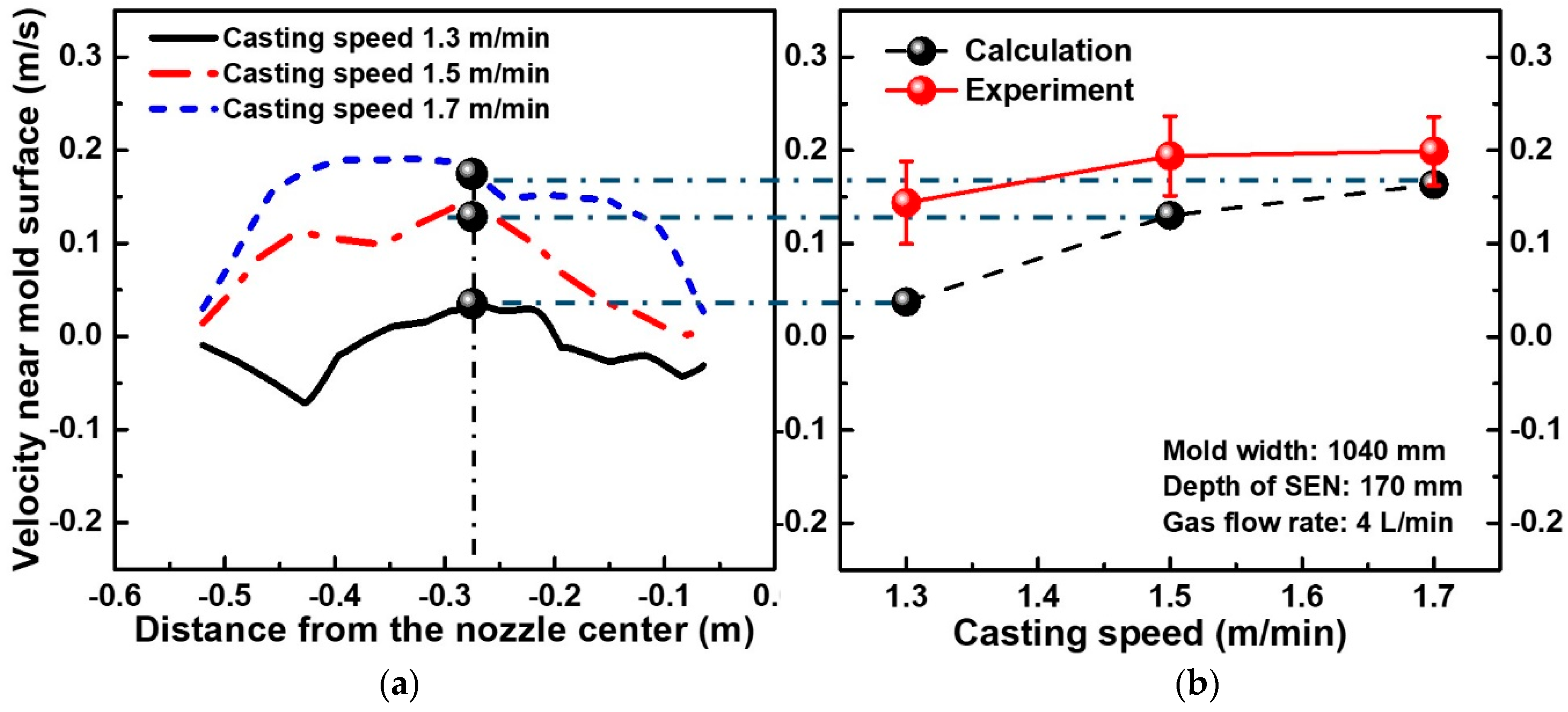
Figure 8 shows the comparison of calculated and measured velocities near the surface with different casting speeds under the conditions that the mold width is 1040 mm, the argon gas flow rate is 4 l/min and the immersion depth of SEN is 170 mm. The results show that velocities of molten steel near the surface increase with increasing casting speed, both from experimental measurement and the calculated results. There is a good agreement between the calculated and measured results in trends as shown in Figure 8b. When the mold width is decreased from 1275 mm to 1040 mm, it is noticed a slight less-prediction of the measured velocity. This may be because the narrow mold width decreases the volume flow rate of molten steel and enhances the influent of bubbles on non-steady flow phenomenon, as the previous work reported [13].
4.2. Flow Patterns in the Mold
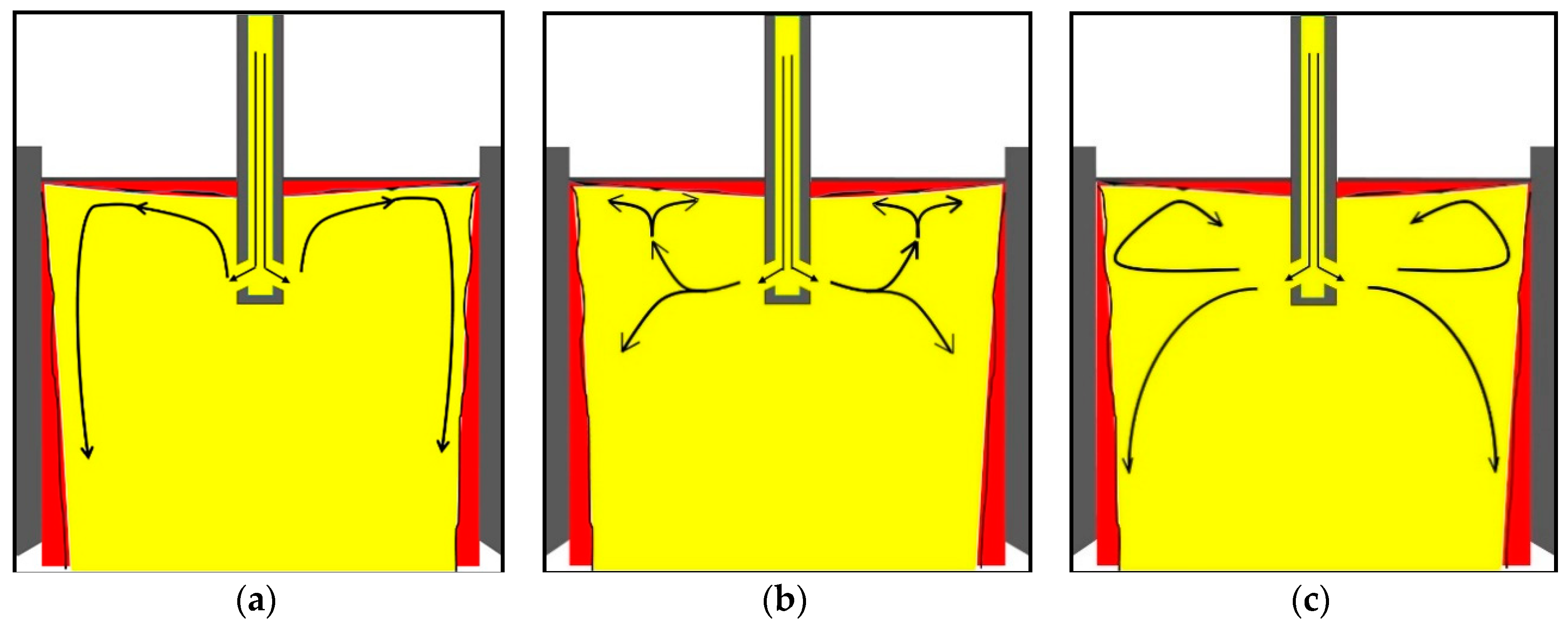
Three different types of flow patterns of molten steel in the mold are shown in Figure 9, which can be obtained from the present calculation and measurement results. The pattern A is the single-roll-flow (SRF) which is formed with increasing argon gas flow rate when the casting speed is small in the wide slab mold. On the contrary, the pattern C is the double-roll-flow (DRF) which is formed with increasing casting speed in the narrow slab mold. The pattern B is a transition state between DRF and SRF and its formation conditions are the reasonable casting speed and argon gas flow rate in the mold.
When the flow pattern is SRF, the strong upward flow and large argon bubbles near the SEN tend to result in the strong surface fluctuation of molten steel. Moreover, the large surface velocity is likely to lead to the longitudinal eddies near the narrow wall, which is one of the main reasons for the slag entrainment into the molten steel. For the flow pattern C, eddies and strong shear force seem to be easily produced by the excessive surface velocity of molten steel, which might result in the slag entrainment near the SEN. In comparison, the flow pattern B is neither cause the vortices nor excessive surface velocity on the meniscus, so the slag entrainment rarely occurs.
By means of the deflection angle measurement, not only the surface velocity but also the flow direction of molten steel can be measured and obtained. Thus, the flow pattern in the mold can be deduced from the flow directions at different positions of the mold. In the present study, the industrial experiments are performed by measuring the flow velocity at two different positions in the mold. One is at the location 10 cm from the narrow wall and the other at the 1/4 mold width.
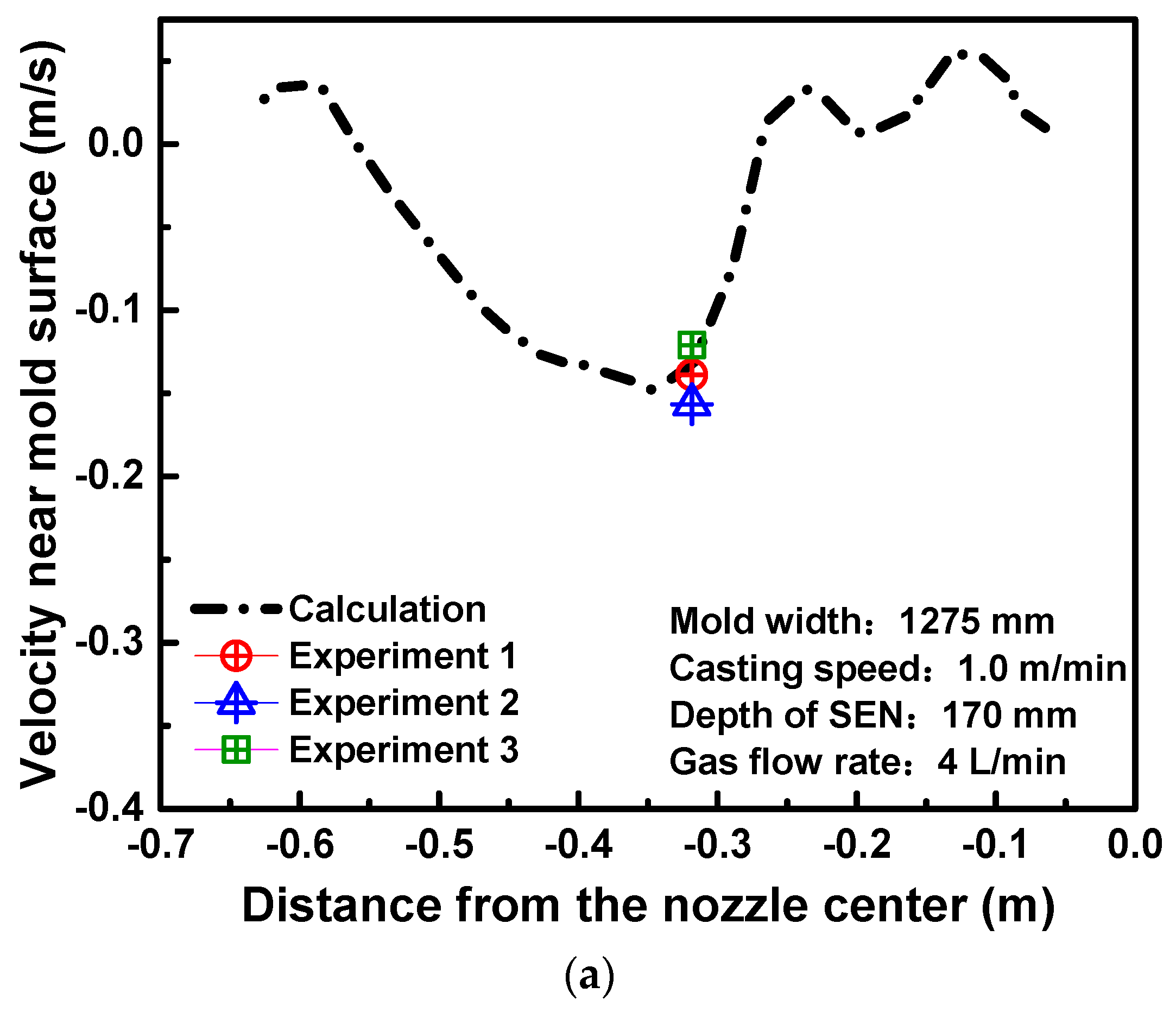
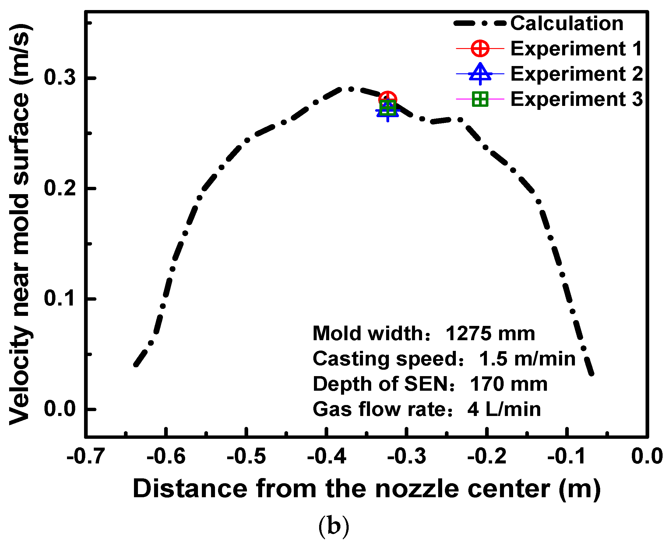
Figure 10 shows the comparison between the calculated and measured velocities of molten steel under the same operation conditions. The black line presents the calculated velocity profiles of 5 cm below the surface along the mold width on the center plane. The experimental data in Figure 10a is measured corresponding to the simulation conditions which are as follows: the mold width is 1275 mm, the casting speed is 1.0 m∙min−1, the depth of SEN is 170 mm and the argon gas flow rate is 4 l∙min−1. Under these conditions, the velocities of molten steel near the surface show negative values at the 1/4 mold width, which indicate that the direction of molten steel flow is from the nozzle to the narrow wall. It is possible that the SRF pattern is formed in the mold. The SRF is an undesirable flow pattern which tends to cause more defects in the slab [38]. The strong upward flow and large argon bubbles near the SEN can result in the surface fluctuation of molten steel which is one of the main reasons for the slag entrainment. On the other hand, the downward flow near the mold narrow wall easily bring the bubbles and inclusions into the depth of mold which can also cause the surface defects. The flow velocity of molten steel is about 0.15 m∙s−1 at the 1/4 width of the mold, which shows the good agreement between the measurement results of the three sets and the calculation result.
In Figure 10b, when the casting speed is increased to 1.5 m/min with the same other parameters as those in Figure 10a, the velocities of molten steel near the surface dramatically change to the positive values, which means the direction of molten steel flow is from the narrow wall to the nozzle. The velocity of molten steel at the 1/4 width of the mold is about 0.28 m∙s−1, which agrees well with the measurement results. Compared with Figure 10a, the flow pattern changes from SRF to DRF with increasing the casting speed. The reason is that the molten steel out from the nozzle outlet ports has a large velocity to reach the narrow wall where the jet splits to flow more strongly upward and downward, which can form a typical DRF.
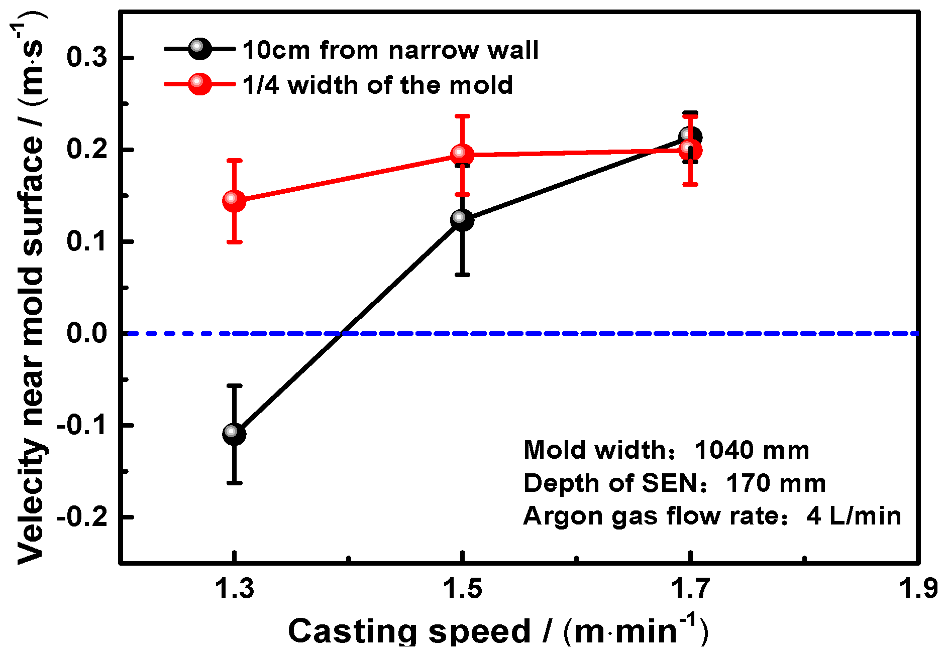
Figure 11 shows the measured velocities of molten steel near the surface at positions of 1/4 width and 10 cm from the narrow wall of the mold under the different casting speeds. The conditions of the experiment are as follows: the mold width is 1040 mm, the depth of SEN is 170 mm and the argon gas flow rate is 4 l∙min−1. No matter at 10 cm from the narrow wall or 1/4 width of the mold, the surface velocities increase with increasing the casting speed. It can be seen that when the casting speed is 1.3 m∙min−1, the flow direction at 1/4 width of the mold is from narrow wall to the nozzle but the flow direction is converse at 10 cm from the narrow wall of the mold. It is likely to indicate that the flow state in the mold is pattern B which is between SRF and DRF. When the casting speed is increased to 1.5 and 1.7 m∙min−1, the flow direction is from narrow wall to the nozzle both at 10 cm from the narrow wall and 1/4 width of the mold, which indicates that the flow pattern in the mold is pattern C of DRF.
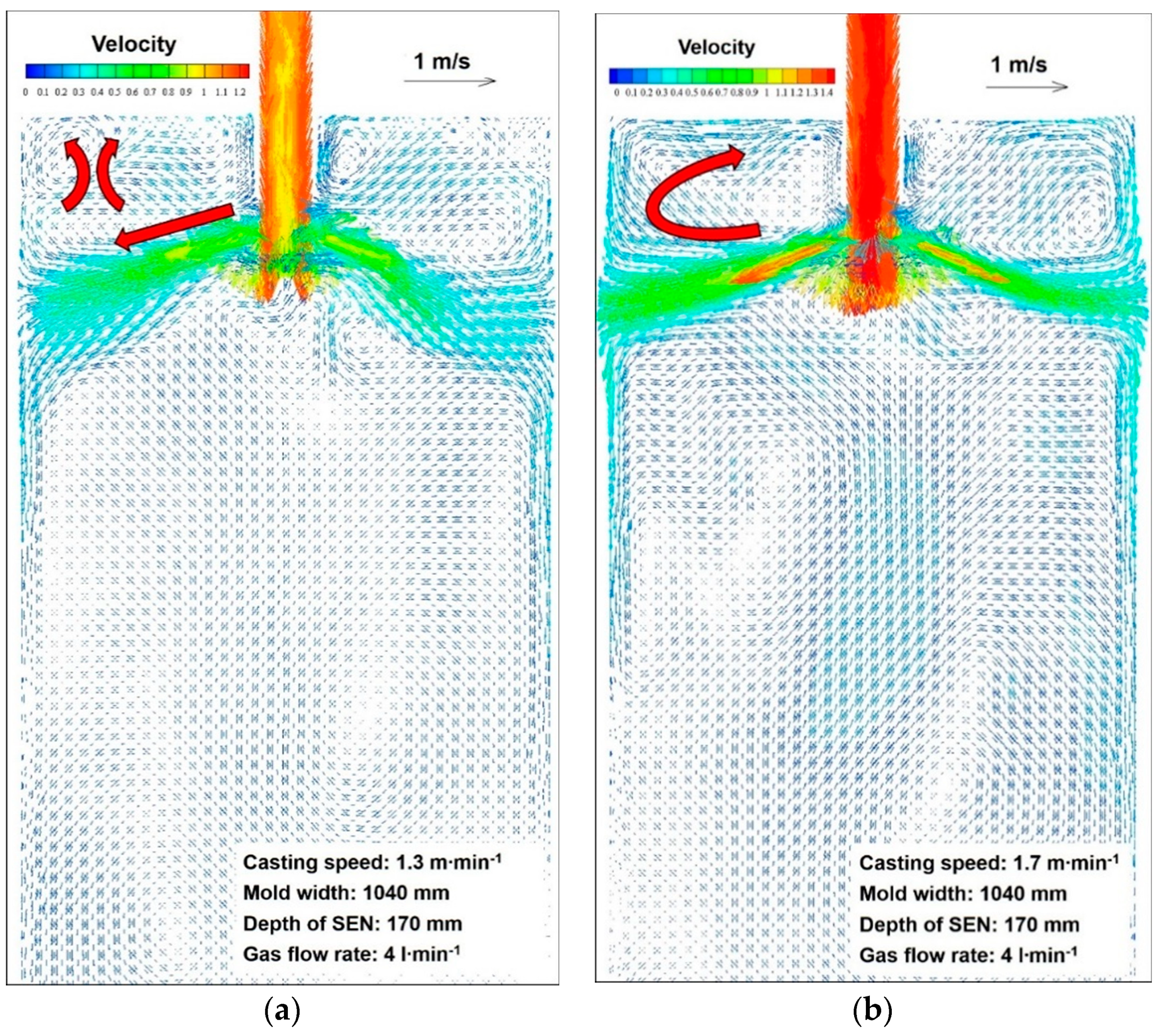
Figure 12 shows the predicted flow field of molten steel in the mold under different casting speeds. The calculated results show a good agreement with the measured results. When the casting speed is 1.3 m∙min−1, the flow direction of molten steel in the upper circulation zone is opposite between the 1/4 mold width and near the narrow face. When the casting speed is 1.7 m∙min−1, the flow pattern in the mold is a typical DRF. It strongly evidences that different casting speeds can change the flow pattern in the mold. In a consequence, the Rod Deflecting Method can be used to judge the flow pattern of the mold and optimize the operation conditions of continuous casting to improve the quality of the slab.
5. Conclusions
In this study, the measurements of molten steel velocity near the mold surface are conducted using a newly developed speed measuring method under the different operation conditions of continuous casting. In addition, the mathematical model is adapted to simulate the flow field of molten steel in the mold. Based on the obtained results, the following conclusions are drawn:
- The rod deflection method is conducted to measure the flow velocity of molten steel near the surface of the mold in the industrial experiment. With this measurement, the flow velocity and direction can be obtained.
- Both experimental and calculated results show that the molten steel velocity near the mold surface increases with increasing casting speed. Furthermore, argon gas injection can slow down the molten steel velocity and uplift the jet zone, due to the buoyancy of bubbles.
- Three different types of flow patterns of molten steel in the CC mold can be obtained from the present calculation and measurement results. The pattern A is the single-roll-flow (SRF) and the pattern C is the double-roll-flow (DRF). The pattern B is a transition state between DRF and SRF, which is neither cause the vortices nor excessive surface velocity on the meniscus, so the slag entrainment rarely occurs.
- It is found both from the measurement results and calculated results of the molten steel velocity near the mold surface that the casting speed can change the flow pattern in the mold. When the argon flow rate is 4 l/min and the casting speed is 1.0 m/min, the SRF will be formed. However, the flow pattern becomes the DRF with increasing the casting speed to larger than 1.3 m/min.
- Good and reasonable agreements have been obtained between the calculated and measured results. Combination of the measurement and calculation results is an effective tool to investigate the transient flow behavior in the CC mold and optimize the actual operation parameters of continuous casting to avoid the surface defects of the automobile outer panel.
Author Contributions
Conceptualization, T.Z. and J.Y.; Methodology, T.Z. and J.Y; Software, T.Z. and P.J; Validation, T.Z., J.Y. and P.J.; Formal analysis, T.Z., J.Y. and P.J.; Investigation, T.Z. and J.Y.; Data curation, T.Z. and P.J.; Writing—original draft preparation, T.Z.; Writing—review and editing, J.Y. and T.Z.
Funding
This research received no external funding.
Conflicts of Interest
The authors declare no conflict of interest.
References
- Wang, X.H. Non-metallic inclusion control technology for high quality cold rolled steel sheets. Iron Steel 2013, 48, 1–7. [Google Scholar]
- Zeze, M.; Tanaka, A.; Tsujino, R. Formation Mechanism of Sliver-type Surface Defects with Oxide Scale on Sheet and Coil. Tetsu-to-Hagane 2001, 87, 15–22. [Google Scholar] [CrossRef]
- Yang, J.; Zhi, J.J.; Wang, R.Z.; Zhu, K. Analysis of involved mold powders and inclusions for the surface defects on car body panels. In Proceedings of the 17th Chinese Steelmaking Conference, Hangzhou, China, 16 May 2013; pp. 809–814. [Google Scholar]
- Wang, X.H. Possibility of producing high quality cold rolled coils with thin slab casting production route. Iron Steel 2004, 39, 18–25. [Google Scholar]
- Yuan, F.M.; Wang, X.H.; Liu, X.M. Research of surface inclusive slag defects in interstitial-free steel slab. Contin. Cast. 2004, 6, 32–35. [Google Scholar]
- Bai, H.; Thomas, B.G. Turbulent flow of liquid steel and argon bubbles in slide-gate tundish nozzles: Part I. Model development and validation. Metall. Mater. Trans. B 2001, 32, 253–267. [Google Scholar] [CrossRef]
- Thomas, B.G. Review on modeling and simulation of continuous casting. Steel Res. Int. 2017, 89, 1700312. [Google Scholar] [CrossRef]
- Zhang, T.; Luo, Z.G.; Liu, C.L.; Zhou, H.; Zou, Z.S. A mathematical model considering the interaction of bubbles in continuous casting mold of steel. Powder Technol. 2015, 273, 154–164. [Google Scholar] [CrossRef]
- Zhu, M.Y.; Cai, Z.Z.; Yu, H.Q. Multiphase flow and thermo-mechanical behaviors of solidifying shell in continuous casting mold. J. Iron Steel Res. Int. 2013, 20, 6–17. [Google Scholar] [CrossRef]
- Liu, Z.; Li, B.; Jiang, M. Transient asymmetric flow and bubble transport inside a slab continuous-casting mold. Metall. Mater. Trans. B 2013, 45, 675–697. [Google Scholar] [CrossRef]
- Thomas, B.G.; Zhang, L. Mathematical modeling of fluid flow in continuous casting. ISIJ Int. 2001, 41, 1181–1193. [Google Scholar] [CrossRef]
- Yuan, Q.; Zhao, B.; Vanka, S.P.; Thomas, B.G. Study of computational issues in simulation of transient flow in continuous casting. Steel Res. Int. 2005, 76, 33–43. [Google Scholar] [CrossRef]
- Chaudhary, R.; Ji, C.; Thomas, B.G.; Vanka, S.P. Transient turbulent flow in a liquid-metal model of continuous casting, including comparison of six different methods. Metall. Mater. Trans. B 2011, 42, 987–1007. [Google Scholar] [CrossRef]
- Kratzsch, C.; Timmel, K.; Eckert, S.; Schwarze, R. Urans simulation of continuous casting mold flow: Assessment of revised turbulence models. Steel Res. Int. 2015, 86, 400–410. [Google Scholar] [CrossRef]
- Liu, C.L.; Luo, Z.G.; Zhang, T.; Deng, S.; Wang, N.; Zou, Z.S. Mathematical modeling of multi-sized argon gas bubbles motion and its impact on melt flow in continuous casting mold of steel. J. Iron Steel Res. Int. 2014, 21, 403–407. [Google Scholar] [CrossRef]
- Wang, Y.F.; Zhang, L.F. Transient fluid flow phenomena during continuous casting: Part 1—cast start. ISIJ Int. 2010, 50, 1777–1782. [Google Scholar] [CrossRef]
- Wang, Y.F.; Zhang, L.F. Transient fluid flow phenomena during continuous casting: Part 2—cast speed change, temperature fluctuation, and steel grade mixing. ISIJ Int. 2010, 50, 1783–1791. [Google Scholar] [CrossRef]
- Thomas, B.G.; Yuan, Q.; Mahmood, S.; Liu, R.; Chaudhary, R. Transport and entrapment of particles in steel continuous casting. Metall. Mater. Trans. B 2014, 45, 22–35. [Google Scholar] [CrossRef]
- Singh, R.; Thomas, B.G.; Vanka, S.P. Effects of a magnetic field on turbulent flow in the mold region of a steel caster. Metall. Mater. Trans. B 2013, 44, 1201–1221. [Google Scholar] [CrossRef]
- Liu, Z.; Li, B.; Zhang, L.; Xu, G. Analysis of transient transport and entrapment of particle in continuous casting mold. ISIJ Int. 2014, 54, 2324–2333. [Google Scholar] [CrossRef]
- Liu, Z.Q.; Li, L.; Li, B.; Jiang, M. Large eddy simulation of transient flow, solidification, and particle transport processes in continuous-casting mold. JOM 2014, 66, 1184–1196. [Google Scholar] [CrossRef]
- Singh, R.; Thomas, B.G.; Vanka, S.P. Large Eddy Simulations of Double-Ruler Electromagnetic Field Effect on Transient Flow During Continuous Casting. Mater. Trans. B 2014, 45, 1098–1115. [Google Scholar] [CrossRef] [Green Version]
- Miki, Y.; Takeuchi, S. Internal defects of continuous casting slabs caused by asymmetric unbalanced steel flow in mold. ISIJ Int. 2003, 43, 1548–1555. [Google Scholar] [CrossRef]
- Chaudhary, R.; Lee, G.G.; Thomas, B.G.; Cho, S.M.; Kim, S.-H.; Kwon, O.D. Effect of stopper-rod misalignment on fluid flow in continuous casting of steel. Metall. Mater. Trans. B 2011, 42, 300–315. [Google Scholar] [CrossRef]
- Yuan, Q.; Thomas, B.G.; Vanka, S.P. Study of transient flow and particle transport in continuous steel caster molds: Part I. Fluid flow. Metall. Mater. Trans. B 2004, 35, 685–702. [Google Scholar] [CrossRef] [Green Version]
- Shen, B.; Shen, H.; Liu, B. Instability of fluid flow and level fluctuation in continuous thin slab casting mould. ISIJ Int. 2007, 47, 427–432. [Google Scholar] [CrossRef]
- Thomas, B.G.; Yuan, Q.; Sivaramakrishnan, S.; Shi, T.; Vanka, S.P.; Assar, M.B. Comparison of four methods to evaluate fluid velocities in a continuous slab casting mold. ISIJ Int. 2001, 41, 1262–1271. [Google Scholar] [CrossRef]
- Sanchez-Perez, R.; Morales, R.D.; Diaz-Cruz, M. A physical model for the two-phase flow in a continuous casting mold. ISIJ Int. 2003, 43, 637–646. [Google Scholar] [CrossRef]
- Kubota, J.; Kubo, N.; Ishii, T. Steel flow control in continuous slab caster mold by traveling magnetic field. NKK Tech. Rev. 2001, 85, 1. [Google Scholar]
- Liu, R.; Thomas, B.G.; Sengupta, J.; Chung, S.D.; Trinh, M. Measurements of molten steel surface velocity and effect of stopper-rod movement on transient multiphase fluid flow in continuous casting. ISIJ Int. 2014, 54, 2314–2323. [Google Scholar] [CrossRef]
- Assar, M.B.; Dauby, P.H.; Lawson, G.D. The 83rd Steelmaking Conference; Iron and Steel Society: Pittsburgh, PA, USA, 2000. [Google Scholar]
- Iguchi, M.; Kawabata, H.; Demoto, Y.; Morita, Z. Cold model experiments for developing a new velocimeter applicable to molten metal. ISIJ Int. 1994, 34, 461–467. [Google Scholar] [CrossRef]
- Iguchi, M.; Terauchi, Y. Karman vortex probe for the detection of molten metal surface flow in low velocity range. ISIJ Int. 2002, 42, 939–943. [Google Scholar] [CrossRef]
- Jones, W.P.; Launder, B.E. The prediction of laminarization with a two-equation model of turbulence. Int. J. Heat Mass Transf. 1972, 15, 301–314. [Google Scholar] [CrossRef]
- Xu, Y.; Ersson, M.; Jönsson, P.G. A numerical study about the influence of a bubble wake flow on the removal of inclusions. ISIJ Int. 2016, 56, 1982–1988. [Google Scholar] [CrossRef]
- Thomas, B.G.; Huang, X.; Sussman, R.C. Simulation of argon gas flow effects in a continuous slab caster. Metall. Mater. Trans. B 1994, 25B, 527. [Google Scholar] [CrossRef]
- Zhang, T.; Luo, Z.; Zhou, H.; Ni, B.; Zou, Z. Analysis of two-phase flow and bubbles behavior in a continuous casting mold using a mathematical model considering the interaction of bubbles. ISIJ Int. 2016, 56, 116–125. [Google Scholar] [CrossRef]
- Deng, X.; Ji, C.; Cui, Y.; Li, L.; Yin, X.; Yang, Y.; McLean, A. Flow pattern control in continuous slab casting moulds: Physical modelling and plant trials. Ironmak. Steelmak. 2016, 44, 461–471. [Google Scholar] [CrossRef]
Figure 1.
Schematic diagram of the measurement method of molten steel velocity near the surface in a mold.
Figure 1.
Schematic diagram of the measurement method of molten steel velocity near the surface in a mold.

Figure 2.
Analysis of the forces acted on a detecting rod.

Figure 3.
Relationship between flow velocity of molten steel and deflection angle of detecting rod with different insertion depths.
Figure 3.
Relationship between flow velocity of molten steel and deflection angle of detecting rod with different insertion depths.

Figure 4.
Geometry (a) and grids (b) of the computational domain.

Figure 5.
Distribution of molten steel velocity along the mold thickness direction. (a) Without gas injection; (b) With gas injection.
Figure 5.
Distribution of molten steel velocity along the mold thickness direction. (a) Without gas injection; (b) With gas injection.

Figure 6.
Comparison of calculated velocity profiles at the different distances from SEN. (a) 80 mm from nozzle center; (b) 270 mm from nozzle center; (c) 530 mm from nozzle center.
Figure 6.
Comparison of calculated velocity profiles at the different distances from SEN. (a) 80 mm from nozzle center; (b) 270 mm from nozzle center; (c) 530 mm from nozzle center.

Figure 7.
Comparison of calculated and measured velocities near the surface with different casting speeds. (a) Calculated results; (b). Comparison of experimental and calculated results
Figure 7.
Comparison of calculated and measured velocities near the surface with different casting speeds. (a) Calculated results; (b). Comparison of experimental and calculated results

Figure 8.
Comparison of calculated and measured velocities near the surface with different casting speeds. (a) Calculated results; (b). Comparison of experimental and calculated results
Figure 8.
Comparison of calculated and measured velocities near the surface with different casting speeds. (a) Calculated results; (b). Comparison of experimental and calculated results

Figure 9.
Different flow patterns of molten steel in the mold. (a) Pattern A (SRF); (b) Pattern B (Transition state); (c). Pattern C (DRF).
Figure 9.
Different flow patterns of molten steel in the mold. (a) Pattern A (SRF); (b) Pattern B (Transition state); (c). Pattern C (DRF).

Figure 10.
Comparison of the calculated and measured molten steel velocities near the surface. (a) Casting speed is 1.0 m/min; (b) Casting speed is 1.5 m/min.
Figure 10.
Comparison of the calculated and measured molten steel velocities near the surface. (a) Casting speed is 1.0 m/min; (b) Casting speed is 1.5 m/min.


Figure 11.
Measured velocities of molten steel near the surface at positions of 1/4 width and 10 cm from the narrow wall of the mold.
Figure 11.
Measured velocities of molten steel near the surface at positions of 1/4 width and 10 cm from the narrow wall of the mold.

Figure 12.
Flow field of molten steel in the mold under different casting speeds. (a) Casting speed is 1.3 m/min; (b) Casting speed is 1.7 m/min
Figure 12.
Flow field of molten steel in the mold under different casting speeds. (a) Casting speed is 1.3 m/min; (b) Casting speed is 1.7 m/min


Table 1.
Geometrical and process parameters.
| Parameters | Values | Parameters | Values |
|---|---|---|---|
| Slab width (mm) | 1040, 1080, 1275 | Fluid density (kg/m3) | 7020 |
| Slab thickness (mm) | 230 | Gravity acceleration (m/s2) | 9.81 |
| Slab length (mm) | 3000 | Gas density (kg/m3) | 0.27 |
| SEN submerged depth (mm) | 170 | Gas bubble radius (mm) | 0.5 |
| Casting speed (m/min) | 1.0, 1.3, 1.5, 1.7 | Gas volume flow (l/min) | 0, 4, 7 |
| Fluid dynamic viscosity(N·s/m2) | 0.0056 | SEN port angle (°) | 20 |
© 2019 by the authors. Licensee MDPI, Basel, Switzerland. This article is an open access article distributed under the terms and conditions of the Creative Commons Attribution (CC BY) license (http://creativecommons.org/licenses/by/4.0/).
Share and Cite
MDPI and ACS Style
Zhang, T.; Yang, J.; Jiang, P. Measurement of Molten Steel Velocity near the Surface and Modeling for Transient Fluid Flow in the Continuous Casting Mold. Metals 2019, 9, 36. https://doi.org/10.3390/met9010036
AMA Style
Zhang T, Yang J, Jiang P. Measurement of Molten Steel Velocity near the Surface and Modeling for Transient Fluid Flow in the Continuous Casting Mold. Metals. 2019; 9(1):36. https://doi.org/10.3390/met9010036
Chicago/Turabian StyleZhang, Tao, Jian Yang, and Peng Jiang. 2019. "Measurement of Molten Steel Velocity near the Surface and Modeling for Transient Fluid Flow in the Continuous Casting Mold" Metals 9, no. 1: 36. https://doi.org/10.3390/met9010036
Note that from the first issue of 2016, this journal uses article numbers instead of page numbers. See further details here.