Article

Investigation of Stress-Oriented Hydrogen-Induced Cracking (SOHIC) in an Amine Absorber Column of an Oil Refinery

by
Gregory N. Haidemenopoulos
1,2,*,
Helen Kamoutsi
2,
Kyriaki Polychronopoulou
1,
Panagiotis Papageorgiou
2,
Ioannis Altanis
3,
Panagiotis Dimitriadis
3 and
Michael Stiakakis
3
1
Department of Mechanical Engineering, Khalifa University of Science and Technology, Abu Dhabi 127788, UAE
2
Department of Mechanical Engineering, University of Thessaly, 38334 Volos, Greece
3
Motor Oil Hellas, Korinth Refinery, 20100 Korinth, Greece
*
Author to whom correspondence should be addressed.
Metals 2018, 8(9), 663; https://doi.org/10.3390/met8090663
Submission received: 4 August 2018 / Revised: 22 August 2018 / Accepted: 22 August 2018 / Published: 24 August 2018
(This article belongs to the Special Issue Failure Mechanisms in Alloys)

Abstract

:
Stress-oriented hydrogen-induced cracking (SOHIC) of an amine absorber column made of a Hydrogen Induced Cracking (HIC) resistant steel and operating under wet H2S service was investigated. SOHIC was not related to welds in the column and evolved in two steps: initiation of HIC cracks in the rolling plane and through-thickness linking of the HIC cracks. Both the original HIC cracks as well as the linking cracks propagated with a cleavage mechanism. The key factors identified were periods with high hydrogen charging conditions, manifested by high H2S/amine ratio, and stress triaxiality, imposed by the relatively large thickness of the plate. In addition, the mechanical properties of the steel away from cracked regions were unaffected, indicating the localized nature of SOHIC.

1. Introduction

Amine absorber columns in oil refineries are columns where a downflowing amine solution absorbs H2S from the upflowing sour gas stream. The H2S-rich amine solution, when exiting the absorber, is routed to a regenerator to produce an H2S-lean amine that is recycled for use in the absorber. Under specific operation conditions, where the ratio of H2S/amine is high, H2S corrosion of the steel shell can take place, producing hydrogen, which can then enter the steel and cause hydrogen blistering and hydrogen-induced cracking. According to American Petroleum Institute standard API 571 [1], it is atomic hydrogen that enters the material and diffuses through the lattice. The hydrogen is then concentrated to various microstructural sites, such as interfaces between the matrix and inclusions or interfaces between the matrix and other phases. The local pressure increases and decohesion takes place, generating internal blistering or so-called hydrogen-induced cracking (HIC). In most cases, HIC cracks are oriented parallel to the rolling plane. Under the action of applied or residual stresses, the HIC cracks arrange in a vertically (through thickness) stacked array. Subsequently, the array is joined by cracks between the individual HIC cracks, which run perpendicular to the main applied stress. The interconnected HIC cracks, which run through the thickness of the plate, form a significant through-thickness crack. This cracking is classified as stress-oriented hydrogen-induced cracking (SOHIC). As mentioned above, hydrogen is produced by a corrosion reaction, such as when steel is exposed to wet H2S service.
Hydrogen damage in wet H2S environments is classified as blistering/HIC/SOHIC/Sulfide Stress Cracking (SSC) in API 571 recommended practice [1], while the assessment of hydrogen damage is performed in accordance with API 579 [2], following the work of Buchheim et al. [3] on the development of fitness-for-service rules for the assessment of HIC and SOHIC damage. While hydrogen blistering and HIC is a frequent problem when steel operates in wet H2S service, SOHIC is a rather rare phenomenon and when occurring is mostly associated with residual stresses at welds. SOHIC in pipelines and pressure vessels has been thoroughly reviewed by Pargeter [4]. Most of the case studies reported associated with SOHIC are related with SOHIC at welds and concern mostly pipelines. There is only one case of SOHIC in an amine absorber column, reported by McHenry et al. [5] regarding the Chicago refinery incident in 1984. Even in this case, SOHIC originated from the Heat Affected Zone (HAZ) of a repair weld, which did not receive a stress-relieving post-weld heat treatment. Following the Chicago refinery incident, the Occupational Safety and Health Administration (OSHA) of the Department of Labor issued in 1986 a memorandum [6] stating, among others, that in a survey of similar refinery vessels and associated equipment conducted by the National Association of Corrosion Engineers (NACE), approximately 60% of 24 amine absorbers evaluated exhibited cracking. In addition, 12 of 14 monoethanolamine (MEA) units and three of five diethanolamine (DEA) units exhibited cracking. Sixteen instances of cracking were reported in associated equipment (i.e., regeneration units and piping) exposed to a chemically similar environment. Additionally, a similar survey by the Japan Petroleum Institute indicated that cracking had occurred in 72% of the amine gas treatment facilities which had responded to the survey.
As mentioned above, most failure cases involving SOHIC refer to welded piping, such as the work by Anezi et al. [7] in spiral welded pipes. The effects of loading and microstructure have been discussed by Kobayashi et al. [8] as well as by Koh et al. [9], while the effects of heat treatment on SOHIC of pressure vessel steels have been discussed by Tsuchida et al. [10]. Most reported results refer to HIC, as does the work of Findley et al. [11] on the mechanism of HIC in pipeline steels and the work of Gan et al. [12] on hydrogen trapping in H2S environments. In situ observation of HIC propagation is reported by Fujishiro et al. [13], while corrosion-induced microcracking in H2S environments has been discussed by Okonkwo et al. [14]. A recent review of HIC in pipelines and pressure vessel steels is presented by Ghosh et al. [15]. The reported cases of SOHIC failures in pressure vessels are limited and mostly associated with welds. The present case refers to SOHIC in the base plate of a pressure vessel, away from welds. This is a rare case and it is, therefore, very important to investigate the conditions and contributing factors of this type of damage.
A decommissioned amine absorber column, which exhibited hydrogen blistering in the internal wall, was made available for study. Blistering is shown in Figure 1. The aim of the present work is to investigate the underlying SOHIC damage and to identify the contributing factors that led to cracking.

2. Materials and Methods

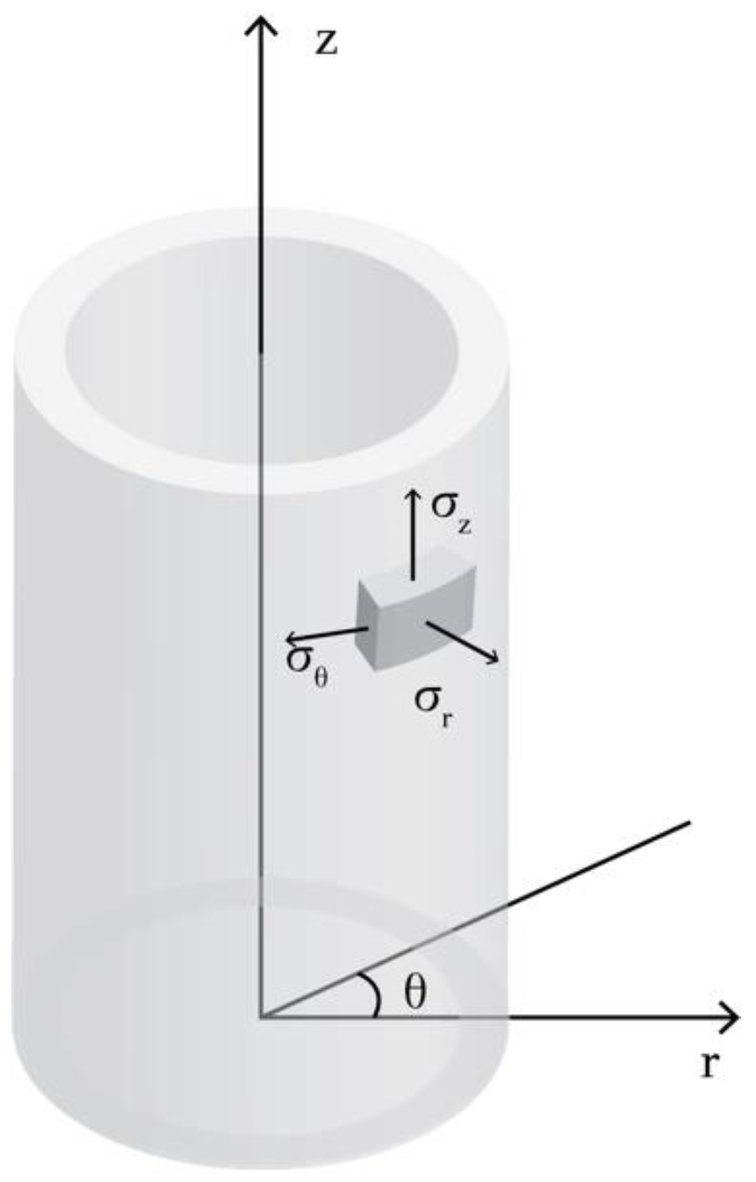
2.1. Operating Conditions and Material of Construction

The column length, without the end cups, is 19 m. The internal diameter is 2.2 m and the shell thickness 91 mm. The service is characterized as wet H2S, H, and amine service. The amine was methyldiethanolamine (MDEA). The operating pressure was 80 kg/cm2 and the operating temperature was 70 °C. The column had been field-hydrotested before operation. In addition, all the welds had been 100% radiographically inspected, while a stress-relieving Post Weld Heat Treatment (PWHT) was performed in all welds. The column operated for 11 years. Following the detection of blistering in the inside diameter (ID), shown in Figure 1, and based on a relevant API level-3 fitness-for-service analysis, a decision was made to replace the vessel. In the 6-month period before replacement, hydrogen permeation measurements were conducted at the outside diameter (OD), indicating hydrogen flux values ranging from 10 to 120 pl/cm2s. It is to be noted that hydrogen flux is related to corrosion activity, by H2S, at the ID. During the 11 years, the vessel operated occasionally at high H2S/MDEA molar ratio, above the normal ratio of 0.3 and reaching values up to 1. It is anticipated that this led to higher corrosion activity and higher hydrogen generation and entry in the material. The system of axes used for reference is shown in Figure 2. A cylindrical coordinate system is selected. The axis of the column is the z axis, while the θ axis is the circumferential direction and the r axis is the thickness direction.
The material of construction was SA516-60 HIC-resistant steel. Typical mechanical properties of the material are: yield strength 283 MPa, ultimate tensile strength 452 MPa, and elongation 39%. The steel was designated as a HIC-resistant steel since special melting practices, such as vacuum induction melting (VIM) and vacuum arc remelting (VAR), were employed during fabrication. Gases dissolved in the liquid during melting, such as oxygen, nitrogen, and hydrogen, escape from the liquid to the vacuum chamber. This reduces porosity and additionally provides for: (a) minimization of inclusion content and (b) inclusion shape control. Normalizing has been applied as the final heat treatment process. In addition, the steel was subjected to a HIC test as per NACE TM-0284 [16].

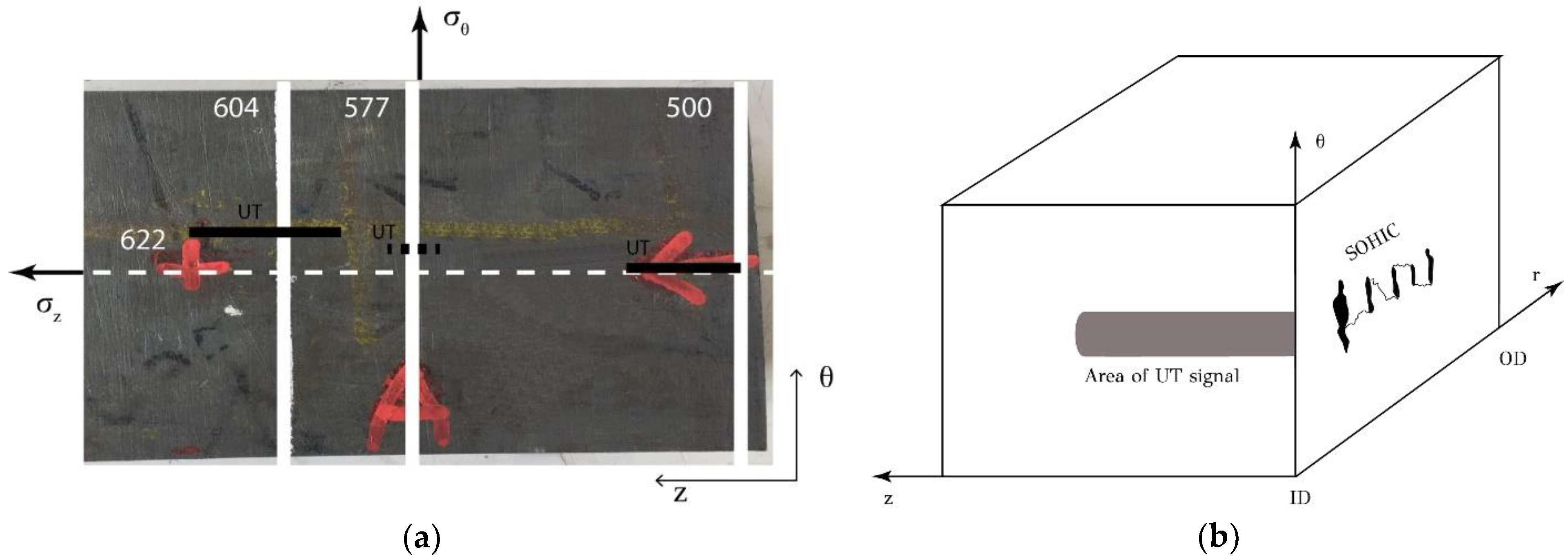
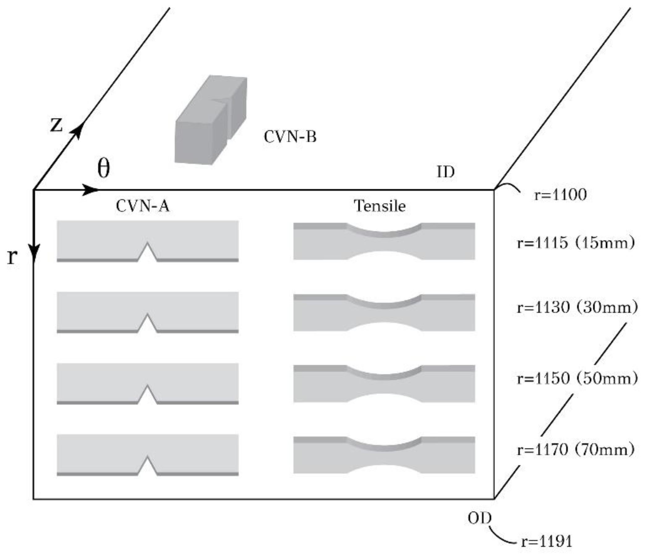
2.2. Sampling Positions

A section of the column shell was cut for investigation. The position of the section was 5 m from the bottom of the column. In the inside diameter, blistering was evident (Figure 1). The shell section is shown in Figure 3. The section was inspected by ultrasonic testing (UT). Locations with UT signals are indicated by thick black horizontal lines (UT) in Figure 3. The positions of the metallographic sections are indicated by perpendicular white lines. Three positions were considered in this work: positions 500, 577, and 604, which pass through the UT signals. The numbers indicate distances, in mm, from a reference point on the vessel shell. It should be noted that the UT signal from position 577 was scattered and not concentrated in a line, as the signals from positions 500 and 604. As will be shown below, the UT signals from positions 500 and 604 correspond to SOHIC cracking, while the signal from position 577 corresponds to HIC, i.e., isolated HIC cracks without linking. An explanation is provided in Figure 3b, correlating the UT signal with the respective metallographic section.

2.3. Experimental Procedures

Chemical analysis of the steel was performed by optical emission spectroscopy. Metallographic analysis was carried out on transverse cross sections at locations 500, 577, and 604. Specimen preparation included cutting with Struers “Accutom 2” (Struers, Ballerup, Denmark), grinding with SiC papers 120, 320, 500, 800, and 1000 grit, and polishing with diamond paste of 3 and 1 μm diameter. Etching was performed with 4% Nital reagent. Examination of the metallographic specimen was performed on an optical metallographic microscope, Leitz “Aristomet” (Leica Camera AG, Germany) at magnifications 50×–500×. Mechanical testing involved tensile testing according to ASTM EN 10002-1 specification and Charpy-V-notch (CVN) impact testing in several locations throughout the thickness, according to ASTM E23 specification. Specimens for mechanical testing were extracted from a region with no UT signals, i.e., a region free from cracking (HIC or SOHIC). The exact locations of the tensile specimens relative to the inside diameter (ID) and outside diameter (OD) are shown in Figure 4. Two tensile specimens were tested for each location. For the CVN testing, three specimen orientations were used, depicted in Figure 4 and Figure 5. In the CVN-A configuration, the specimen length is along the transverse direction (θ) and the notch is in the thickness (r) direction. In the CVN-B configuration, the specimen length is along the longitudinal axis (z) of the vessel shell and the notch in the transverse (θ) direction. In the CVN-C configuration, the specimen length is along the thickness direction of the shell (r) and the notch in the transverse direction (θ). Two impact test specimens were tested for each location.
The crack at location 604 was opened for fractographic analysis. In order to open the crack, a section containing the crack was cut and cooled to −30 °C for 24 h. Then, the section containing the crack was put in an anvil. The crack was opened by impact on one side of the section with a hammer. A small section of “fresh” fracture area was generated. Investigation of the fracture surface was performed in a JEOL JSM-7610F SEM (JEOL, Tokyo, Japan) equipped with a field emission gun. The operating voltage was 20 kV.

3. Results

3.1. Material Characterization

The chemical composition of the material is, in wt %: 0.16 C/0.20 Si/1.13 Mn/0.01 P/(<0.01 S). The tensile properties are shown in Table 1. In addition to yield strength, ultimate tensile strength, and elongation, the elastic modulus was determined to be 210 GPa. In general, the measured properties agree with the manufacturer’s data. Although there is a slight decrease in the ultimate tensile strength relative to the manufacturer’s data, the elongation of the material is high and indicates a ductile material. This argument is also in agreement with the impact test results, which are shown in Table 2, Table 3 and Table 4 for CVN-A, CVN-B, and CVN-C configurations, respectively. All notch configurations exhibited high impact values that do not indicate any deterioration of the notch ductility of the material in the regions away from cracking. In other words, the observed cracking was highly localized.

3.2. Metallographic Characterization of SOHIC

The microstructure of the steel is depicted in the micrograph of Figure 6, indicating that the microstructure consists of ferrite and pearlite. The metallographic section at location 604 is shown in Figure 7, which is an assembly of micrographs starting from the inside diameter (ID) of the shell. This is a typical form of stress-oriented hydrogen-induced cracking (SOHIC). Although, microscopically, the crack direction changes several times during propagation, macroscopically, it is a through-thickness crack with a direction perpendicular to the applied stress. The crack appears to interconnect blisters/HIC cracks, which have formed at various levels across the thickness of the plate. The HIC cracks lie on the rolling plane and are stacked normal to the rolling plane. The HIC cracks are linked with cracks which run in a direction normal to the rolling plane and perpendicular to the applied hoop stress. The initiation is at 5 mm from the ID, while the overall crack length is 23 mm.
The metallographic section at location 577 is depicted in Figure 8a. Blisters/HIC cracks have formed, but they are not interconnected, at least at the plane of observation. This can explain the scattered mode of the UT signal at position 577. The propagation of HIC cracks is through the ferrite phase, between the pearlite colonies at ferrite/pearlite interfaces, as depicted in Figure 8b. A similar crack propagation mechanism has been also observed by Gingel and Garat [17] in an API 5L grade X60 pipeline steel.
The metallographic section at location 500 is depicted in Figure 9. The crack has initiated at 5 mm from the ID and has an overall length of 30 mm. This type of cracking is also classified as SOHIC.
Both cracks at locations 500 and 604 (Figure 7 and Figure 9) are, therefore, classified as SOHIC. They interconnect blisters/HIC cracks and they propagate from the ID towards the OD under the action of the applied stress. According to API RP 571 [1], SOHIC consists of arrays of small HIC cracks, initiated at internal blisters in the rolling plane. These HIC cracks are stacked in a direction normal to the applied hoop stress and are linked by cracks normal to the stress. SOHIC should not be confused with stepwise hydrogen-induced cracking (SWC), which exhibits a not-aligned stepped morphology in the absence of stress. The limited cases of SOHIC failures that are reported in Pargeter’s review [4] indicate that SOHIC requires a combination of severe hydrogen cracking conditions and stress. In the present case, the amine absorber column was operated under high H2S/MDEA ratios for certain time periods, promoting high hydrogen charging conditions. In addition, it has been suggested [4] that triaxial loading can encourage the formation of small HIC cracks by increasing the hydrogen solubility in the steel. Stress triaxiality can be induced by the large plate thickness (91 mm). It is expressed by the ratio σ h / σ ¯ , where σ h is the hydrostatic stress and σ ¯ is the von Mises equivalent stress. The triaxiality ratio was calculated (see Appendix A) for the operating conditions and was found as 0.5, which is a number indicating that the material was subjected to a moderate triaxial stress state. In addition, it is interesting to note that the HIC cracks form even though the radial stress is compressive. However, these cracks do not propagate in the rolling plane, but instead they are linked in the radial direction under the action of the hoop stress.

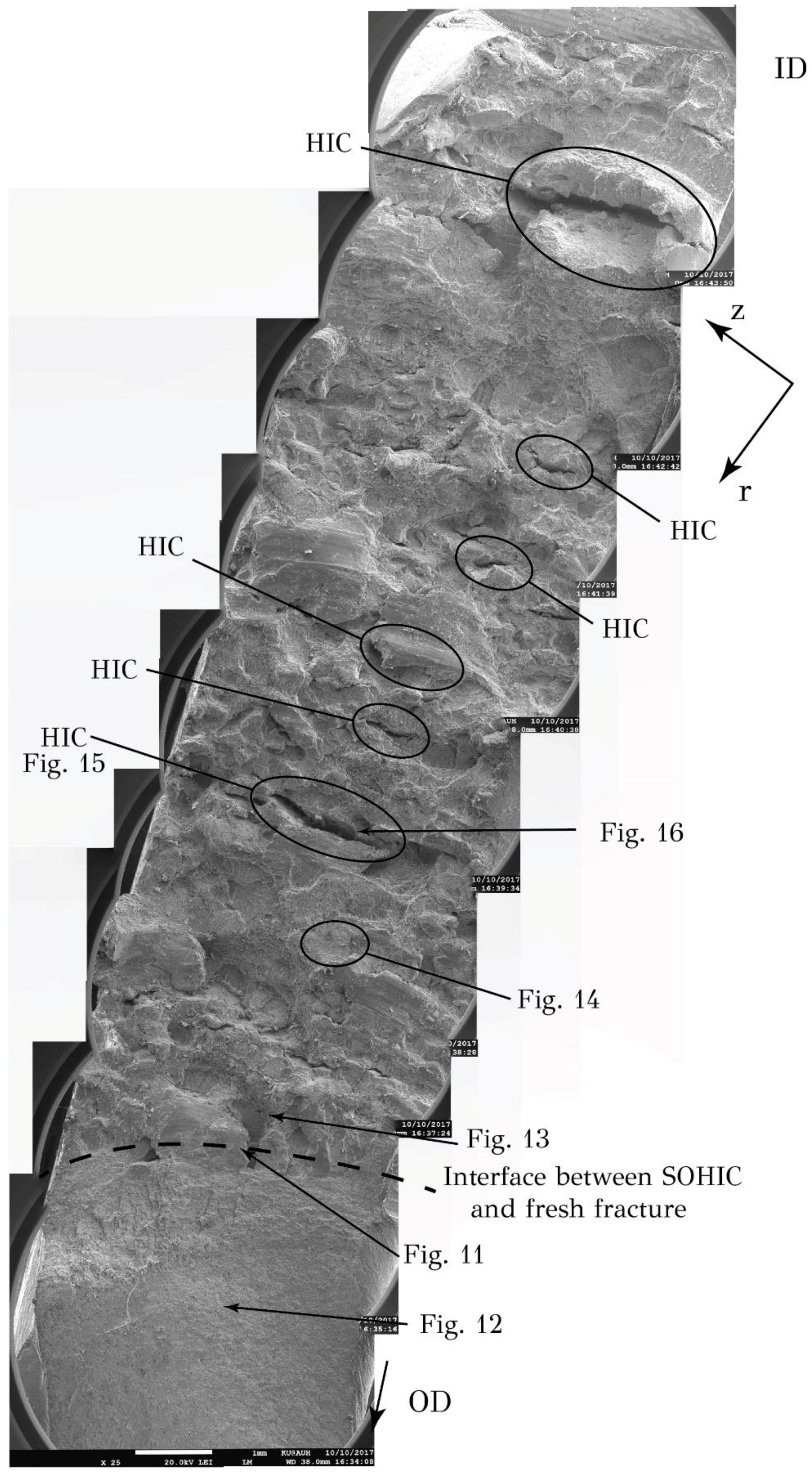
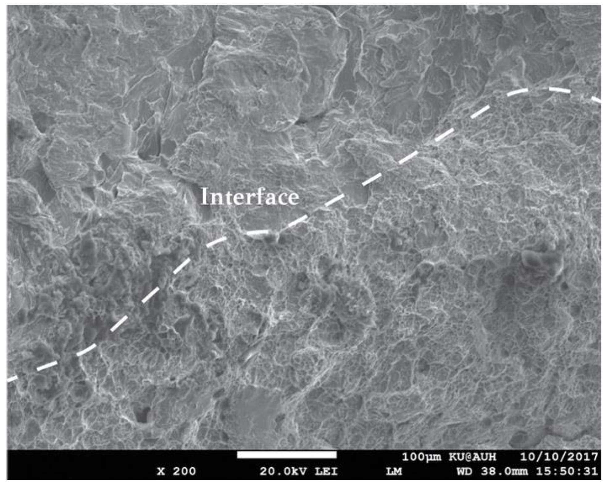
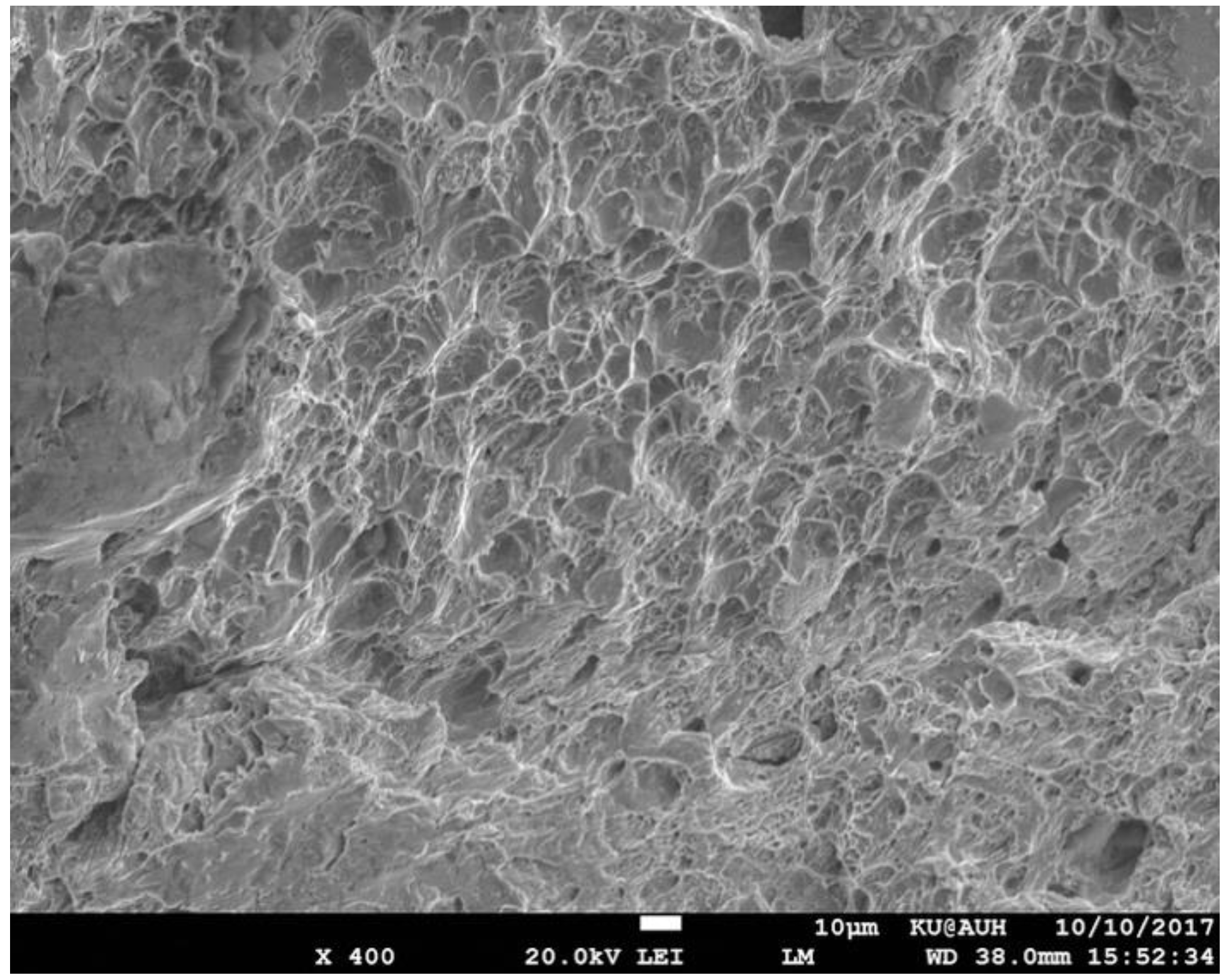
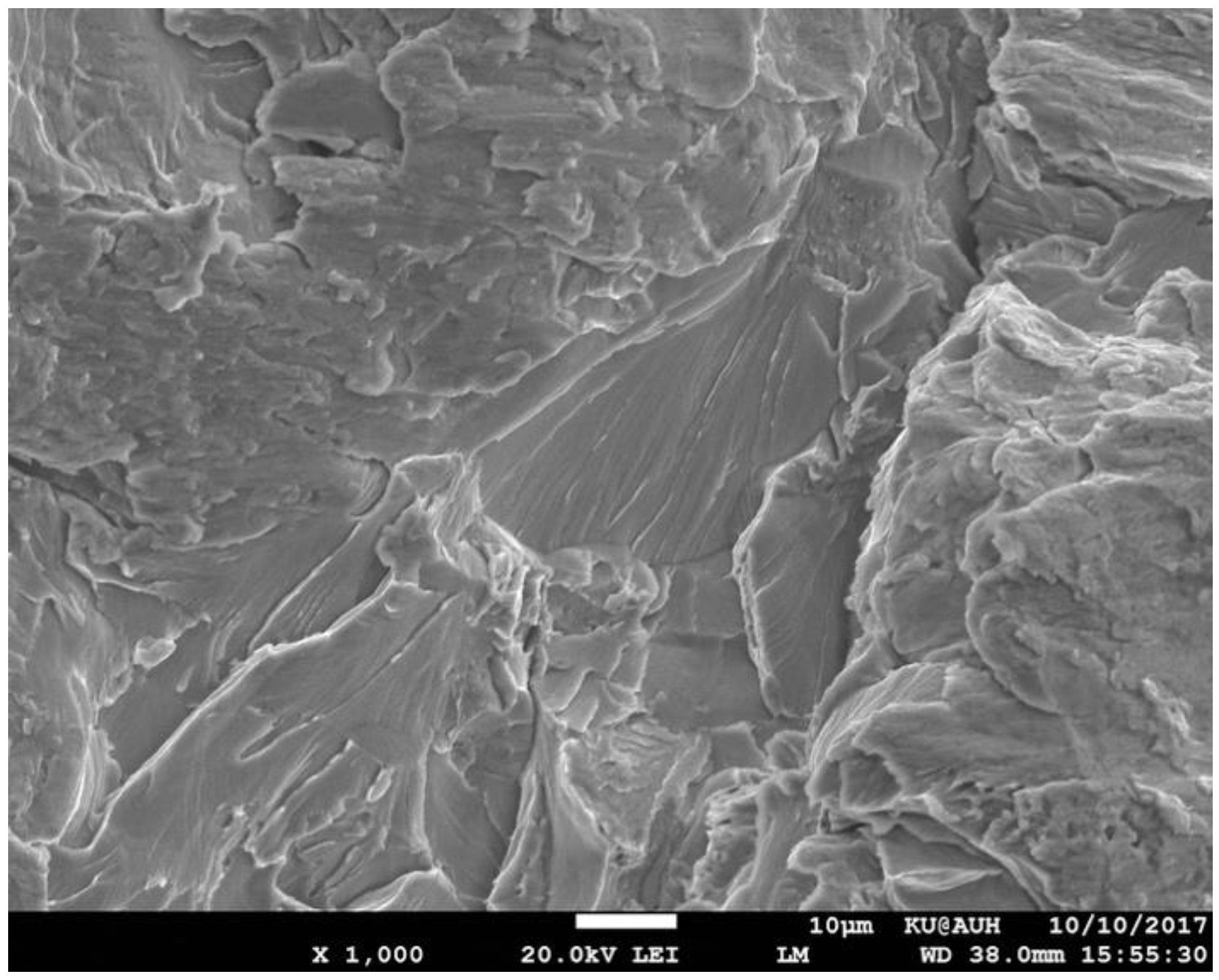
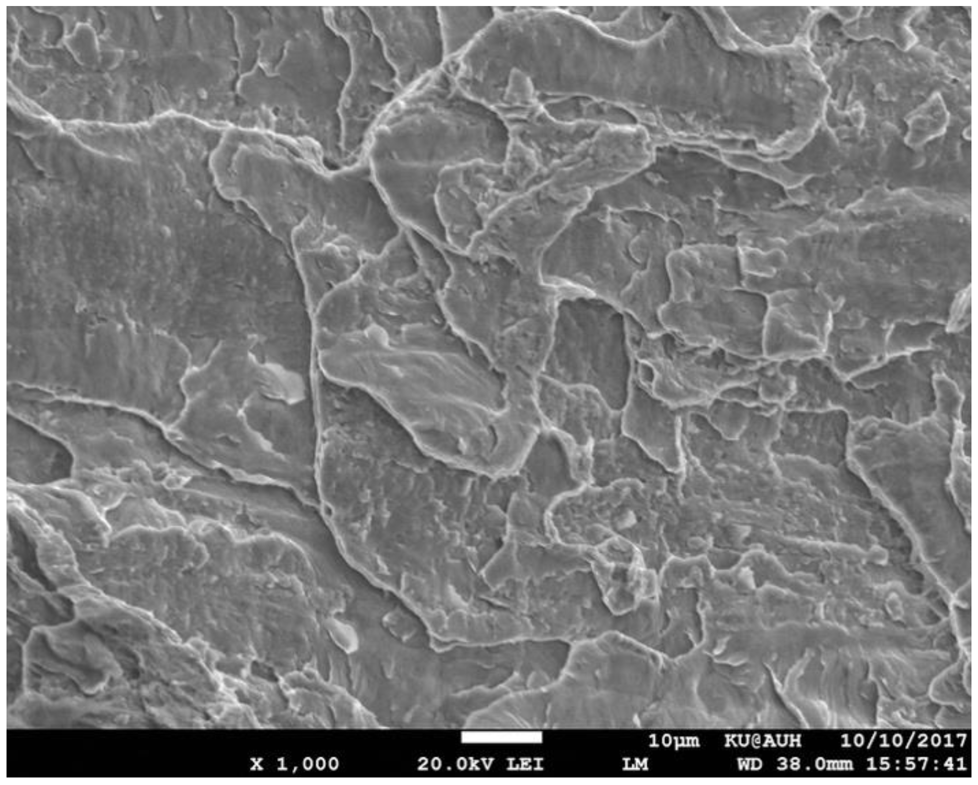
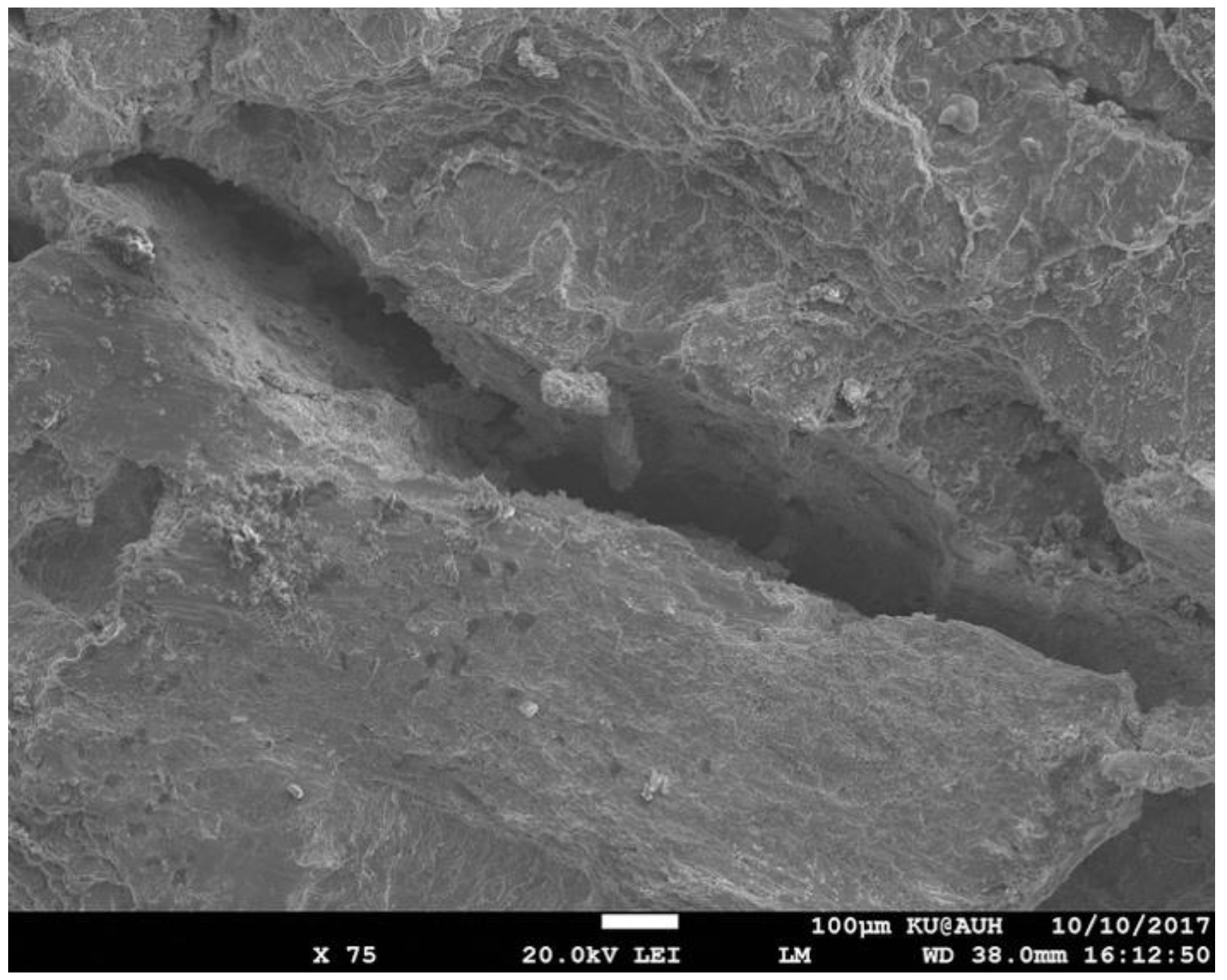
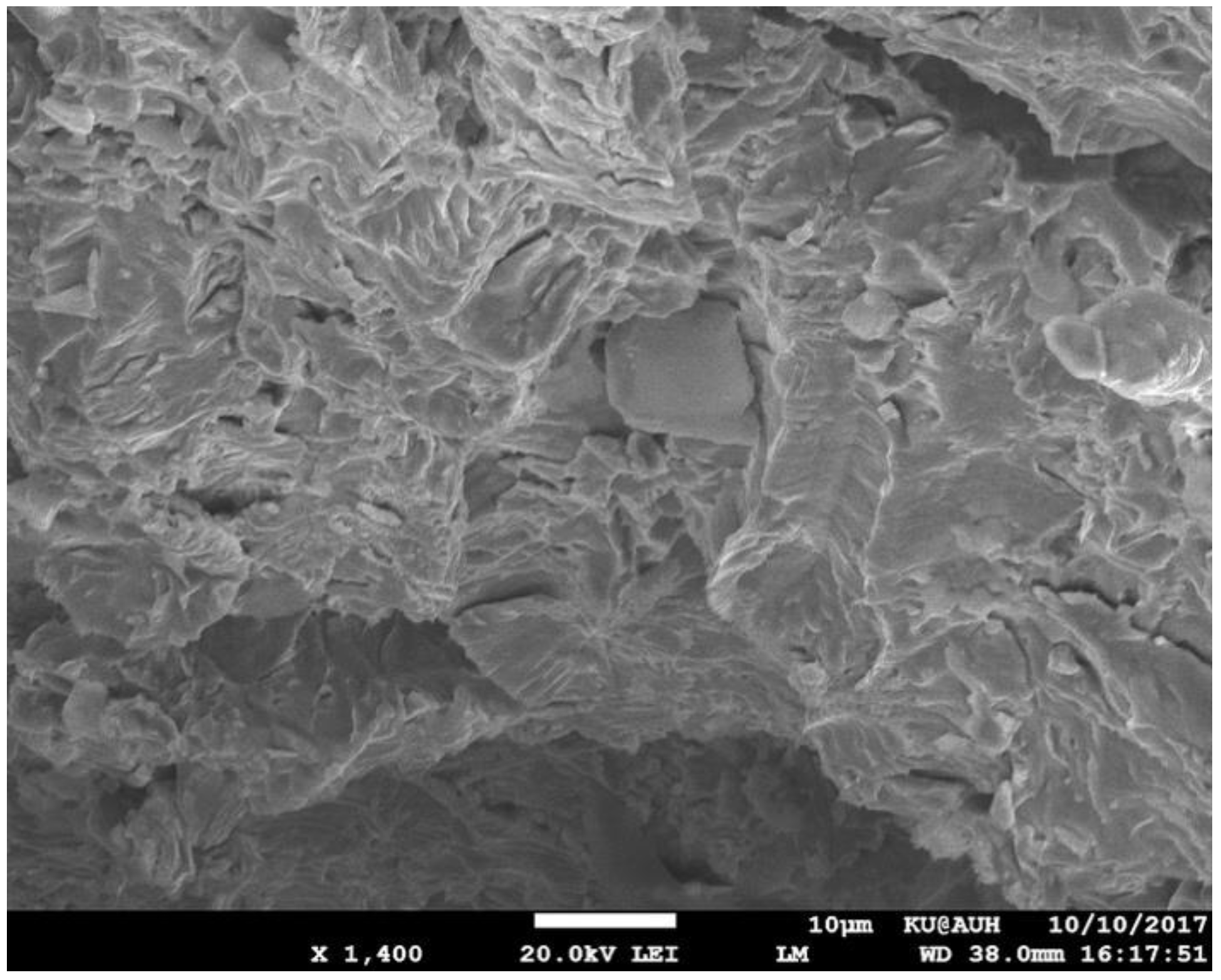
3.3. Fractographic Analysis of Opened SOHIC Crack

As discussed above, the SOHIC crack at location 500 was opened for fractographic analysis. A low-magnification assembly of SEM micrographs is shown in Figure 10. The region of “fresh” fracture resulting by the opening procedure and the region of SOHIC fracture are indicated. The boundary between the fresh fracture and SOHIC is depicted in Figure 11. It is clear that there are two fracture modes. The fresh fracture area is characterized by dimple fracture, also indicated in Figure 12, while the SOHIC area is characterized by cleavage, indicated in Figure 13. In addition, several blisters/HIC cracks can be seen on the fracture surface. The entire SOHIC region, including the areas between blisters, is characterized by cleavage as indicated in Figure 14. No black deposit, related to FeS, was found on the fracture surface. In addition, Energy Dispersive X-ray (EDX) analysis performed on the cleavage areas did not detect the presence of sulfur. The absence of black deposits and sulfur indicate clearly that cracking is not related to sulfide stress cracking (SSC). A large blister/HIC crack is depicted in Figure 15. It was possible to approach the interior of this blister in order to investigate the morphology of the blister wall as it resulted by the HIC crack opening due to the buildup of hydrogen pressure. The internal wall is depicted in Figure 16, indicating a cleavage fracture surface. Thus, blistering and HIC cracking proceeded with cleavage of the material.
It is important to note that location 577 exhibited only stacked HIC cracks with no evidence of crack linking. This indicates that the SOHIC sequence involves the formation of HIC cracks first, followed by through-thickness linking of the HIC cracks, in agreement with observations by Crolet and Adam [18] and Ohki et al. [19]. Both HIC formation and linking involve transgranular cleavage fracture mechanisms as indicated by the fractographic analysis of the opened crack at location 500. The transgranular propagation mode is in agreement with the findings of Bruckhoff et al. [20]; however, the cleavage mode of linking is not in agreement with the suggestion of Pargeter [4] that linking is through a slip mechanism, or that of Azevedo [21], who observed ductile fracture mode in linking hydrogen blisters in an API 5L X46 steel. Slip may be involved in the transport of hydrogen, as shown by several studies [22,23], but the propagation of the linking cracks is clearly through a cleavage mechanism. The cleavage mode of the linking cracks confirms the important influence of stress triaxiality in SOHIC, since triaxiality introduces plastic constraint and promotes cleavage fracture. Triaxiality effects have been discussed by other investigators, such as the effect on hydrogen concentration by Toribio et al. [24], the effect on ductility by Mirza et al. [25], and the effect on fracture behavior by Borvik et al. [26].

4. Discussion: Implications for H2S/Amine Service

The results presented above indicated that the failure mechanism of the absorber column, which operated under wet H2S conditions, was SOHIC. The main characteristic of SOHIC is the presence of HIC cracks lying on the rolling plane, stacked one on top of the other, and linked with cracks running perpendicular to the hoop stress. The SOHIC sequence involves the formation of HIC cracks first, followed by through-thickness linking of the HIC cracks. The major contributing factors have been: (a) high hydrogen charging conditions, since for some time periods, the vessel operated under high H2S/MDEA ratios; and (b) stress triaxiality, imposed by the relatively large thickness of the plate. The role of these two factors have been discussed thoroughly above. An additional factor that may have to be considered is the type of steel used for the construction of the vessel. As discussed in the review by Ossai et al. [27], there is a need for high-quality steel, free from inclusions and other microstructural defects that could act as sites for hydrogen-related crack initiation. For wet H2S service, it is typical to use a HIC-resistant steel. However, as indicated by the resulting cracking, a HIC-resistant steel might not be SOHIC-resistant, in particular when subjected to high hydrogen charging conditions. This argument has also been raised by Pargeter [4]. As mentioned above, inclusions could act as potential sites for HIC. It appears that clean steels, such as the HIC-resistant steels, contain fewer stringer-type inclusions than conventional steels. In these cases, HIC is rather initiated on other interfaces, such as ferrite–pearlite interfaces. The metallographic analysis at the 577 position revealed that HIC cracks propagate in the ferrite matrix between pearlite colonies, as also observed in [28]. It is apparent that the use of a HIC-resistant steel should not be the only measure for mitigating SOHIC. Current practice in the fabrication of pressure vessels operating in similar environments calls for the use of austenitic stainless-steel lining in order to reduce hydrogen diffusion and hydrogen entry to the steel plate. In addition, operating conditions should be carefully monitored to minimize service under high H2S/amine ratios.
Finally, it is important to note that the results of mechanical testing indicated that the ductility of the steel in regions away from the observed cracking has not deteriorated. Tensile elongation and notch ductility were maintained at high levels. However, even in a highly localized form, SOHIC did take place, indicating the type of hydrogen damage that can take place in an otherwise ductile material.

5. Conclusions

Taking into account the results presented above, the following conclusions can be drawn:
(1) The cracking in the amine absorber column shell is classified as stress-oriented hydrogen-induced cracking (SOHIC).
(2) SOHIC proceeds in two steps: (a) initiation of small HIC cracks lying in the rolling plane and stacked in a direction normal to the applied stress; (b) through-thickness linking of HIC cracks.
(3) The propagation of the HIC cracks as well as the through-thickness link cracks is associated to cleavage fracture mechanisms.
(4) The key factors identified in this failure were: (a) short periods of high hydrogen charging conditions as manifested by high H2S/MDEA ratios and (b) stress triaxiality imposed by the relatively large thickness of the plate.
(5) The results indicate that a HIC-resistant steel might not be immune from SOHIC. Under high hydrogen charging conditions, HIC cracks can initiate at interfaces other than stringer-type inclusions, such as ferrite–pearlite interfaces in the microstructure of the steel.

Author Contributions

G.N.H. supervised the work and wrote the manuscript; H.K., P.P. and K.P. performed various aspects of the experimental work. I.A., D.P. and M.S. provided operational data and specimens for the investigation. All authors contributed to the analysis of the results.

Funding

This research received no external funding.

Acknowledgments

The provision of operational data and specimens for this investigation by Motor Oil Hellas is greatly appreciated.

Conflicts of Interest

The authors declare no conflict of interest.

Appendix A

The stresses in the shell of a thick-wall cylindrical vessel subjected to an internal pressure are
σ z = ( p i r i 2 p o r o 2 ) / ( r o 2 r i 2 )
σ θ = [ ( p i r i 2 p o r o 2 ) / ( r o 2 r i 2 ) ] [ r i 2 r o 2 ( p o p i ) / ( r 2 ( r o 2 r i 2 ) ) ]
σ r = [ ( p i r i 2 p o r o 2 ) / ( r o 2 r i 2 ) ] + [ r i 2 r o 2 ( p o p i ) / ( r 2 ( r o 2 r i 2 ) ) ]
where σz, σθ, and σr are the axial, circumferential (hoop), and radial stresses, respectively; pi and po are the internal and external pressures, respectively; and ri and ro are the internal and external radii of the cylinder, respectively. Inserting pi = 8 MPa, po = 0.1 MPa, ri = 1100 mm, and ro = 1191 mm, then at position r = 1110 mm, i.e., 10 mm from the internal surface, the stresses are σz = 45.8 MPa, σθ = 98.5 MPa, and σr = −7 MPa. Stress triaxiality is defined by the ratio σ h / σ ¯ , where σ h is the hydrostatic stress and σ ¯ is the von Mises equivalent stress given by:
σ h = 1 3 ( σ z + σ θ + σ r )
σ ¯ = 1 2 [ ( σ z σ θ ) 2 + ( σ θ σ r ) 2 + ( σ r σ z ) 2 ]
Inserting the above values for stresses, the triaxiality ratio is derived as σ h / σ ¯ = 0.5 .

References

  1. American Petroleum Institute. API RP 571, Damage Mechanisms Affecting Fixed Equipment in the Refining and Petrochemical Industries, 2nd ed.; American Petroleum Institute: Washington, DC, USA, 2011. [Google Scholar]
  2. American Petroleum Institute. API RP 579, Fittness-for-Service; American Petroleum Institute: Washington, DC, USA, 2007. [Google Scholar]
  3. Buchheim, G.M.; Osage, D.A.; Staats, J.C. Development of fitness-for-service rules for the assessment of hic and SOHIC damage in API 579-1/ASME FFS-1. In Proceedings of the ASME 2008 Pressure Vessels and Piping Conference, Chicago, IL, USA, 27–31 July 2008; pp. 761–775. [Google Scholar]
  4. Pargeter, R.J. Susceptibility to SOHIC for linepipe and pressure vessel steels—review of current knowledge. In Proceedings of the International Corrosion Conference, Nashville, TN, USA, 11–15 March 2007. [Google Scholar]
  5. McHenry, H.I.; Shives, T.R.; Read, D.T.; McColskey, J.D.; Brady, C.H.; Purtscher, P.T. Examination of a Pressure Vessel that Ruptured at the Chicago Refinery of the Union Oil Company on July 23 1984; Occupational Safety & Health Administration, US Department of Labor: Washington, DC, USA, 1986.
  6. Occupational Safety and Health Administration (OSHA). Potentially Hazardous Amine Absorber Pressure Vessels Used in Refinery Processing, Memorandum to OSHA Regional Administrators; US Department of Labor: Washington, DC, USA, 1986. Available online: https://www.osha.gov/laws-regs/standardinterpretations/1986-04-11 (accessed on 28 October 2017).
  7. Al-Anezi, M.A.; Rao, S. Failures by SOHIC in sour hydrocarbon service. J. Fail. Analysis Prev. 2011, 11, 363–371. [Google Scholar] [CrossRef]
  8. Kobayashi, K.; Dent, P.; Fowler, C.M. Effects of stress conditions and microstructure on SOHIC susceptibility. In Proceedings of the International Corrosion Conference, San Antonio, TX, USA, 9–13 March 2014. [Google Scholar]
  9. Koh, S.U.; Jung, H.G.; Kang, K.B.; Park, G.T.; Kim, K.Y. Effect of microstructure on hydrogen-induced cracking of linepipe steels. Corrosion 2008, 64, 574–585. [Google Scholar] [CrossRef]
  10. Tsuchida, Y.; Naruoka, Y.; Tokunaga, Y. Effects of heat treatment conditions on SOHIC in normalized steel plates for pressure vessel use. J. High Press. Inst. Jpn. 1996, 34, 9–15. [Google Scholar] [CrossRef]
  11. Findley, K.O.; O’Brien, M.K.; Nako, H. Critical assessment 17: Mechanisms of hydrogen induced cracking in pipeline steels. Mater. Sci. Technol. 2015, 31, 1673–1680. [Google Scholar] [CrossRef]
  12. Gan, L.; Huang, F.; Zhao, X.; Liu, J.; Cheng, Y.F. Hydrogen trapping and hydrogen induced cracking of welded X100 pipeline steel in H2S environments. Int. J. Hydrogen Energy 2018, 43, 2293–2306. [Google Scholar] [CrossRef]
  13. Fujishiro, M.T.; Hara, D.T. In-situ observation of hydrogen induced cracking propagation behavior. Corrosion 2018. Available online: http://corrosionjournal.org/doi/abs/10.5006/2757 (accessed on 16 June 2018). [CrossRef]
  14. Okonkwo, P.; Shakoor, R.; Benamor, A.; Amer Mohamed, A.; Al-Marri, M. Corrosion behavior of API X100 steel material in a hydrogen sulfide environment. Metals 2017, 7, 109. [Google Scholar] [CrossRef]
  15. Ghosh, G.; Rostron, P.; Garg, R.; Panday, A. Hydrogen induced cracking of pipeline and pressure vessel steels: A review. Eng. Fract. Mech. 2018, 199, 609–618. [Google Scholar] [CrossRef]
  16. NACE International. Evaluation of Pipeline and Pressure Vessel Steels for Resistance to Hydrogen-Induced Cracking; NACE International: Houston, TX, USA, 2003. [Google Scholar]
  17. Gingell, A.; Garat, X. Observations of damage modes as a function of microstructure during NACE TM-01-77/96 tensile testing of API 5L grade X60 linepipe steels. In Proceedings of the International Corrosion Conference, San Antonio, TX, USA, 25–30 April 1999. [Google Scholar]
  18. Crolet, J.L.; Adam, C. SOHIC without H2S. Mater. Perform. 2000, 39, 86–90. [Google Scholar]
  19. Ohki, T.; Tanimura, M.; Kinoshita, K.; Tenmyo, G. Effect of inclusions on sulphide stress cracking. In Proceedings of the Symposium on Stress Corrosion—New Approaches, Montreal, QC, Canada, 22–27 June 1975; pp. 399–419. [Google Scholar]
  20. Bruckhoff, W.; Geier, O.; Hofbauer, K.; Schmitt, G.; Steinmetz, D. Rupture of a sour gas line due to stress orientated hydrogen induced cracking-Failure analyses, experimental results and corrosion prevention. In Proceedings of the NACE CORROSION/85 Conference, Boston, MA, USA, 25–29 March 1985; p. 389. [Google Scholar]
  21. Azevedo, C.R.F. Failure analysis of a crude oil pipeline. Eng. Fail. Anal. 2007, 14, 978–994. [Google Scholar] [CrossRef]
  22. Miyoshi, E.; Tanaka, T.; Terasaki, F.; Ikeda, A. Hydrogen-induced cracking of steels under wet hydrogen-sulfide environment. J. Eng. Ind. 1976, 98, 1221–1230. [Google Scholar] [CrossRef]
  23. Robertson, I.M.; Sofronis, P.; Nagao, A.; Martin, M.L.; Wang, S.; Gross, D.W.; Nygren, K.E. Hydrogen embrittlement understood. Metall. Mater. Trans. B 2015, 46, 1085–1103. [Google Scholar] [CrossRef]
  24. Toribio, J.; Kharin, V.; Vergara, D.; Lorenzo, M. Hydrogen diffusion in metals assisted by stress: 2D numerical modelling and analysis of directionality. Solid State Phenom. 2015, 225, 33–38. [Google Scholar] [CrossRef]
  25. Mirza, M.S.; Barton, D.C.; Church, P. The effect of stress triaxiality and strain-rate on the fracture characteristics of ductile metals. J. Mater. Sci. 1996, 31, 453–461. [Google Scholar] [CrossRef]
  26. Børvik, T.; Hopperstad, O.S.; Berstad, T. On the influence of stress triaxiality and strain rate on the behaviour of a structural steel. Part ii. Numerical study. Eur. J. Mech. 2003, 22, 15–32. [Google Scholar] [CrossRef]
  27. Ossai, C.I.; Boswell, B.; Davies, I.J. Pipeline failures in corrosive environments—A conceptual analysis of trends and effects. Eng. Fail. Anal. 2015, 53, 36–58. [Google Scholar] [CrossRef]
  28. Cayard, M.S.; Kane, R.D.; Cooke, D.L. An exploratory examination of the effect of sohic damage on the fracture resistance of carbon steels. In Proceedings of the International Corrosion Conference, New Orleans, LA, USA, 9–14 March 1997. [Google Scholar]
Figure 1. Blistering in internal surface.
Metals 08 00663 g001
Figure 2. System of axes used for the positioning of specimens.
Metals 08 00663 g002
Figure 3. (a) Shell section for analysis (top view) indicating locations of metallographic sections and positions of UT signals; (b) correlation of SOHIC with UT signal (SOHIC: Stress Oriented Hydrogen Induced Cracking, ID: Inside Diameter, OD: Outside Diameter, UT: Ultrasonic Testing).
Metals 08 00663 g003
Figure 4. Positions of tensile specimens as well as Charpy-V-Notch, CVN-A and CVN-B specimens relative to ID and OD.
Metals 08 00663 g004
Figure 5. Positions of the CVN-C specimens relative to ID and OD.
Metals 08 00663 g005
Figure 6. Ferrite–pearlite microstructure of the investigated steel.
Metals 08 00663 g006
Figure 7. SOHIC cracking at location 604.
Metals 08 00663 g007
Figure 8. (a) HIC cracks at location 577; (b) tip of HIC crack indicating propagation in ferrite between pearlite colonies.
Metals 08 00663 g008
Figure 9. SOHIC at location 500.
Metals 08 00663 g009
Figure 10. Assembly of SEM micrographs depicting the fracture surface of the opened SOHIC crack at position 500. The location of HIC cracks and individual SEM micrographs is indicated.
Metals 08 00663 g010
Figure 11. Boundary between SOHIC and “fresh” fracture.
Metals 08 00663 g011
Figure 12. Dimple fracture in the “fresh” fracture region.
Metals 08 00663 g012
Figure 13. Cleavage fracture at SOHIC region.
Metals 08 00663 g013
Figure 14. Cleavage fracture in SOHIC region between HIC cracks.
Metals 08 00663 g014
Figure 15. A large HIC crack at the SOHIC fracture region.
Metals 08 00663 g015
Figure 16. Cleavage fracture morphology of the internal blister/HIC crack wall.
Metals 08 00663 g016
Table 1. Tensile test results at different locations throughout the thickness of the plate.
Location (mm from ID)Yield Strength (MPa)UTS (MPa)Elongation (%)
1529043246.4/45.06
3028743042.26/37.2
5029143938.0/39.4
7028643840.4/38.5
Manufacturer Data283–285445–45238–39
Table 2. Results from CVN-A impact test configuration.
Notch Position (mm from ID)Specimen IDCVN Energy (J)CVN Average (J)
15A1/A5186/194190
30A2/A6184/180182
50A3/A7170/186178
70A4/A8168/168168
Table 3. Results from CVN-B impact test configuration.
Notch Position (mm from ID)Specimen IDCVN Energy (J)CVN Average (J)
15B1/B5186/178182
30B2/B6216/188202
50B3/B7190/192191
70B4/B8184/182181
Table 4. Results from CVN-C impact test configuration.
Notch Position (mm from ID)Specimen IDCVN Energy (J)CVN Average (J)
27.5C3/C6170/186178
36C2/C5154/160156
63.5C1/C4186/190188

