Article

Optimization of Sintering Time and Holding Time for 3D Printing of Fe-Based Metallic Glasses

School of Mechanical Science and Engineering, Jilin University, Renmin Street 5988, Changchun 130025, China
*
Author to whom correspondence should be addressed.
Metals 2018, 8(6), 429; https://doi.org/10.3390/met8060429
Submission received: 20 May 2018 / Revised: 31 May 2018 / Accepted: 4 June 2018 / Published: 6 June 2018

Abstract

:
Fe-based metallic glasses are amorphous alloys with high strength, high hardness, and excellent corrosion resistance; however, the immaturity of processing methods has prevented their wide application in industrial production. Fe-based metallic glass parts were manufactured employing pneumatic injection additive manufacturing in this study. An evenly dispersed and stable Fe-based metallic glass powder slurry with a solids content of 50% was prepared firstly. Then the Fe-based metallic glass parts were printed. The printed parts were dried, debinded, and sintered for strengthening. The deformations of the printed parts and sintered parts relative to the original model were then analyzed by a 3D scanning reconstruction method. The slightly average bulging and sunken deformation of the printed parts and sintered parts confirmed the good printing accuracy of the pneumatic injection manufacture system. The effects of the sintering temperature and holding time on the properties of the sintered parts were studied. For a sintering temperature of 580 °C and holding time of 1 h, the surface quality of the sintered parts was better. The sintering of 3D-printed Fe-based metallic glass parts was preliminarily realized in this study, and the feasibility of preparing Fe-based metallic glass using pneumatic injection additive manufacture was verified.

1. Introduction

Fe-based metallic glass was the earliest commercialized amorphous system because of its large supercooled liquid region, excellent mechanical properties, abrasion resistance, corrosion resistance, excellent soft magnetic properties, and highly efficient preparation [1,2,3]. However, because the process of forming Fe-based metallic glass is not yet mature, even though it was used early in industrial production, it has only been applied in limited fields such as thermal spraying, transformers, and magnetic element production [4].
Traditional machining methods cannot be used to prepare Fe-based metallic glass because of its metastable properties [5]. Recently, researchers have used additive manufacture to prepare Fe-based metallic glass parts [6,7]. Jung et al. prepared Fe-based metallic glass using the laser selective melting technique and investigated the effect of processing parameters, such as the scanning speed and laser power, on the densification and soft magnetic properties [8]. Li et al. successfully fabricated Fe-based metallic glass with high strength and high fracture toughness using laser sintering. These authors also reported that doping Fe-based amorphous alloys with Cu and Cu-Ni alloys could effectively eliminate the microcracking produced during the sintering process [9]. However, as it is difficult to control the temperature during laser sintering, Fe-based metallic glass prepared using this technique tends to crystallize. Furthermore, this technology requires complex equipment, including a high-energy laser and protective gas. These factors lead to high expenses for the use and maintenance of laser sintering equipment, preventing its wide application in industrial production.
Pneumatic injection additive manufacture is also known as slurry direct writing technology. It is a non-mold forming method based on the principle of pneumatic injection that uses a liquid suspension, slurry, or colloid as the printing material [10,11,12]. Recently, the technology of pneumatic injection additive manufacture has been widely used in the additive manufacture of metals [13,14,15], ceramics [16,17], batteries [18], biomedical engineering scaffolds [19,20], and biological tissue [21]. Jakus et al. used poly(lactic-co-glycolic acid) (PLGA) as a binder and prepared iron oxide, nickel oxide, and copper oxide powder slurries to print complex three-dimensional structures using pneumatic injection manufacture and studied the tensile and compressive properties of the printed parts [22]. Pneumatic injection manufacture has the advantages of low equipment cost, high injection pressure, and wide material selection, and provides a novel alternative for the 3D forming of Fe-based metallic glass. In this study, based on the characteristics of Fe-based metallic glass, an Fe-based metallic glass powder slurry was prepared. Three-dimensional parts made of Fe-based metallic glass were fabricated using pneumatic injection manufacturing technology. The printed parts were dried, debinded, and sintered in the supercooled liquid region. The effect of the sintering parameters on the properties of the sintered parts was studied, and the sintering formation of 3D-printed Fe-based metallic glass was preliminarily realized.

2. Experiment

2.1. Preparation of Fe-Based Metallic Glass Slurry

To prepare the Fe-based metallic glass slurry, deionized water was used as the solvent, ammonium polyacrylate (PAA-NH4) was used as the dispersant, hydroxypropyl methylcellulose (HPMC) was used as the binder, and Silok4013 (Guangzhou Silok Polymer Co., Ltd., Guangzhou, China) was used as the defoamer. These components were mixed in proportion and then combined with spherical Fe-based metallic glass powder with a diameter of 5–75 μm using high-energy ball milling in a planetary ball mill for 12 h. The powder we used in the study was provided by Beijing ZJLG Amorphous Technology Co., Ltd., Beijing, China. The composition of the Fe-based amorphous alloy used is shown in ref [23]. A dispersed and stabilized metallic glass powder slurry with a solid content of 50% was obtained [23].

2.2. 3D Printing and Deformation Analysis of Fe-Based Metallic Glass Parts

The ball-milled Fe-based metallic glass powder slurry was loaded into a 10 mL plastic needle cylinder. The diameter of the nozzle was 0.41 mm, and an injection pressure of 3.0 bar, platform speed of 9 mm/s, printing layer thickness of 0.4 mm, and pressure delay of 0.15 s were used. The slurry was printed on a glass substrate using a pneumatic injection manufacture system. After the printed part was dried, a noncontact 3D scanner (3D EaScan-T Scanner, Shining Three-Dimensional Limited Company, Hangzhou, China) was used to scan the printed and sintered parts to obtain 3D point cloud data. Geomagic software was then used to process the point cloud data to generate three-dimensional entities. The three-dimensional entitles were compared with the original model to analyze the deformations of the printed and sintered parts.

2.3. Sintering of 3D-Printed Fe-Based Metallic Glass Parts

3D-printed parts rely on organic molecular chains and bound water to maintain their shape and therefore exhibit low strength. In this study, after being dried, debinded, and sintered, the organic matter and water molecules among the powder particles were removed, and the powder particles were fused with each other; therefore, parts with high density and high strength could be obtained.
The 3D-printed Fe-based metallic glass parts were placed in a drying box and dried at 60 °C for 3 h, 30 °C for 9 h, and ambient temperature for 24 h. The thermogravimetric analysis (TGA) is shown in Figure 1. The organic decomposition is divided in four steps and the mass losses at these steps are 0.17%, 1.12%, 0.81%, and 0.64%, respectively. Based on the TGA, the debinding schedule was increased to 350 °C at a rate of 3 °C/min and held for 20 min, then increased to 390 °C at 3 °C/min and held for 20 min, and finally increased to 450 °C at 3 °C/min and held for 20 min; at this time, the debinding amount was the closest to the proportion of organic matter.
The glass transition temperature and crystallization temperature of the original Fe-based metallic glass powder were determined using differential scanning calorimetry (DSC). Thermal analysis of the Fe-based metallic glass powders was performed using DSC (Mettler DSC823e) in an argon atmosphere, and the temperature was increased at a rate of 10 °C/min. Different sintering temperatures were selected between the glass transition temperature and crystallization temperature, and the effects of the sintering temperature and holding time on the properties of the sintered parts were investigated using a vacuum sintering furnace (SG-XQL1400, Institute of Optics and Fine Mechanics, CAS, Shanghai, China) under a vacuum of 30 KPa. The crystallization degree of the sintered parts was analyzed by X-ray diffraction (BRUKER Co., Karlsruhe, Germany, D8 ADVANCE). The microstructure of the sintered parts was observed by scanning electron microscopy (XL-30 ESEM, FEI, Hillsboro, OR, USA).

3. Results and Discussion

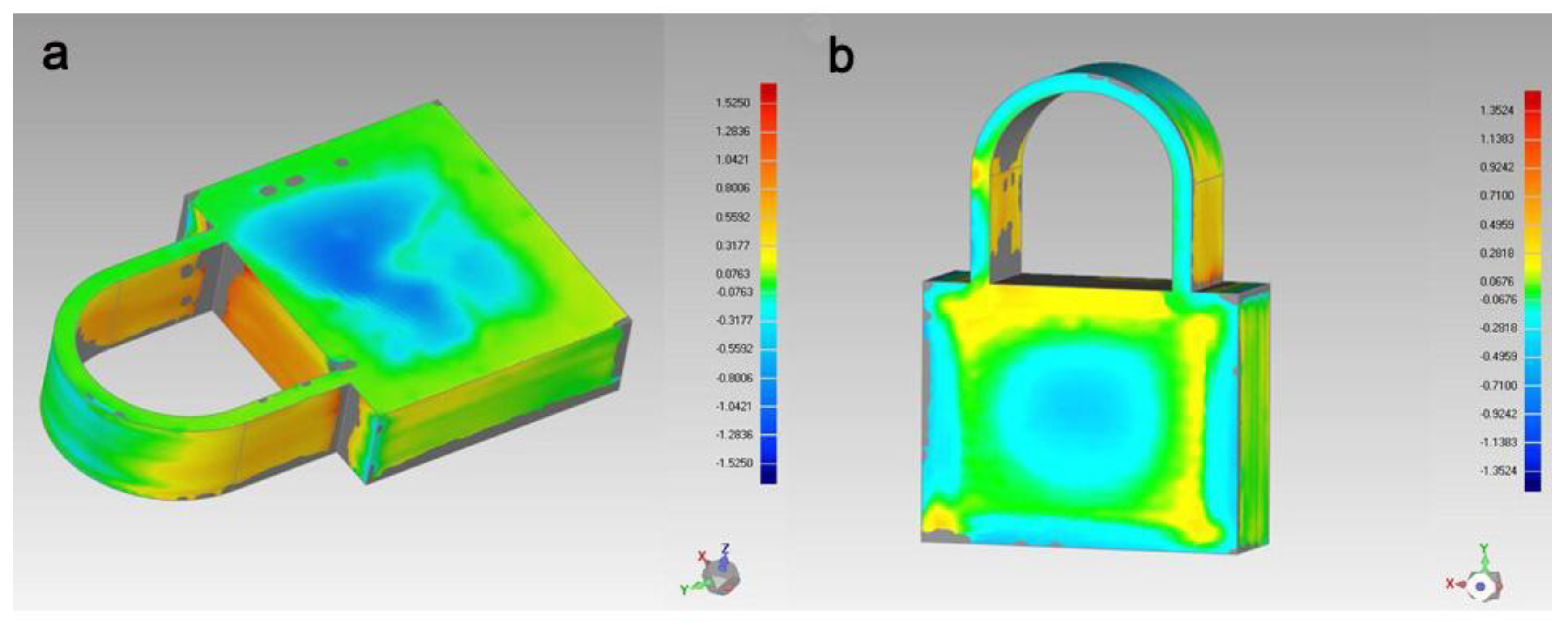
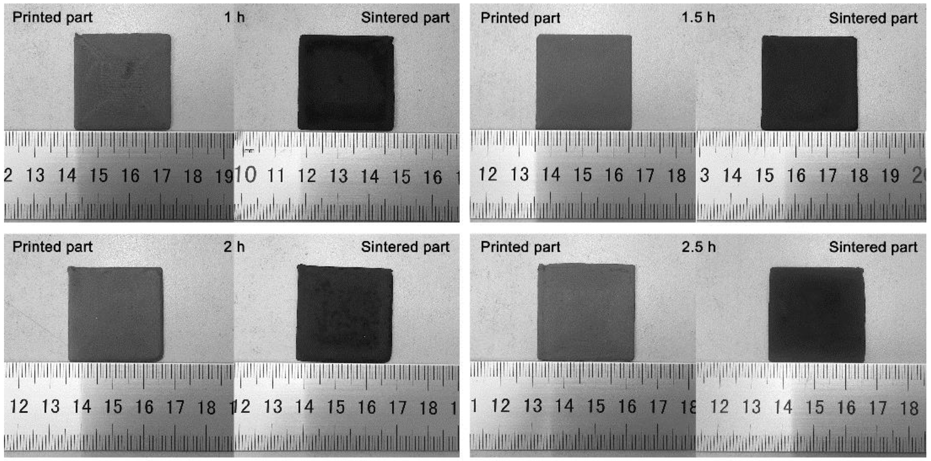
3.1. Analysis of Deformation of 3D-Printed Fe-Based Metallic Glass Parts

The lock-shaped part printed in this study is shown in Figure 2a. Three-dimensional scanning of the printed and sintered lock-shaped parts was performed, and the reconstructed three-dimensional model is presented in Figure 2b,c. Deformation analysis of the printed and sintered parts was performed by comparing the reconstructed 3D models with the original CAD model, and the results are presented in Figure 3a,b, respectively. For the lower half of the printed part, the deformation in the central part was larger than that of the two sides, and the deformation was mainly sunken; in contrast, for the upper half, the deformation of the two sides was larger than that of the central part, and the deformation was mainly bulging. The maximum bulging and sunken deformations were 1.525 mm and 1.4691 mm, respectively, and the average bulging and sunken deformations were 0.256 mm and 0.2283 mm, respectively. The standard deviation of the deformation was 0.3387 mm. These results confirm the good printing accuracy of the pneumatic injection additive manufacturing system. The deformation of the sintered part was reduced compared with that of the printed part. The maximum bulging and sunken deformations were 1.3524 mm and 1.1405 mm, respectively, and the average bulging and sunken deformations were 0.1959 mm and 0.2405 mm, respectively. The standard deviation of the deformation was 0.2791 mm.

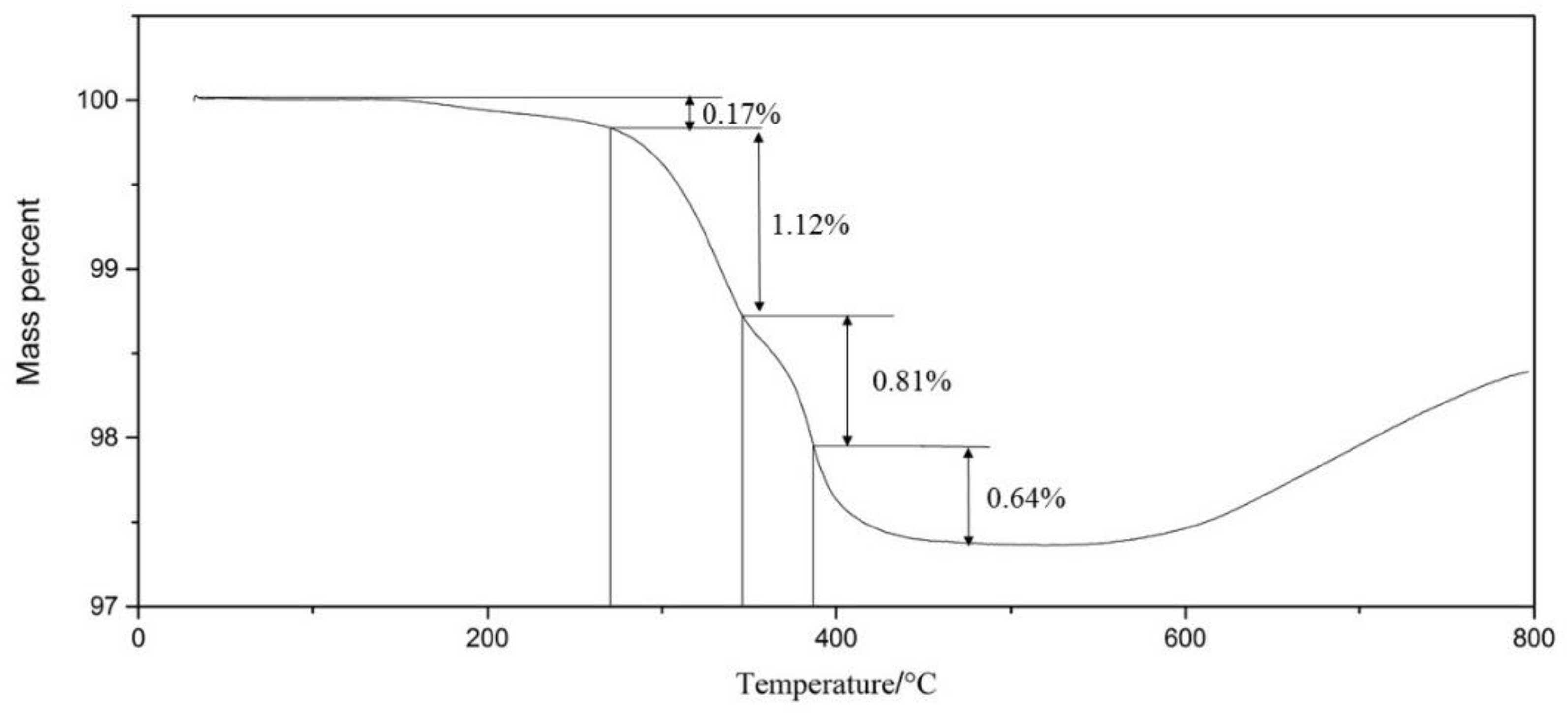
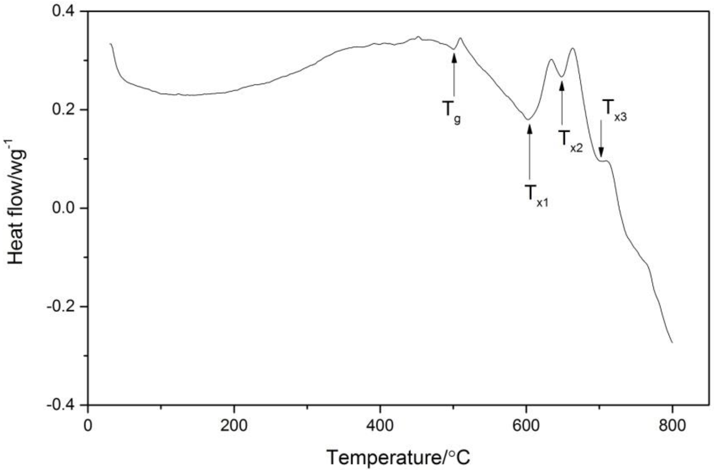
3.2. Differential Thermal Analysis of Fe-Based Metallic Glass Powder

The results of the DSC test are presented in Figure 4. The Fe-based metallic glass powders underwent an obvious endothermic reaction during the heating process as well as glass transition and crystallization processes. Clear steps are observed in the DSC curve at 501 °C, and a clear endothermic peak appeared before the exothermic peak. The glass transition temperature was 501 °C. After the glass transition, three consecutive exothermic peaks appeared at 602 °C, 647 °C, and 702 °C. These peaks indicate that during the heating process, the crystallization of the Fe-based metallic glass occurred in three stages. After that, the material transformed from a supercooled state to a stable crystalline phase. The glass transition temperature of the Fe-based metallic glass was Tg = 501 °C, the first crystallization temperature was T×1 = 602 °C, the second crystallization temperature was T×2 = 647 °C, and the third crystallization temperature was T×3 = 702 °C.

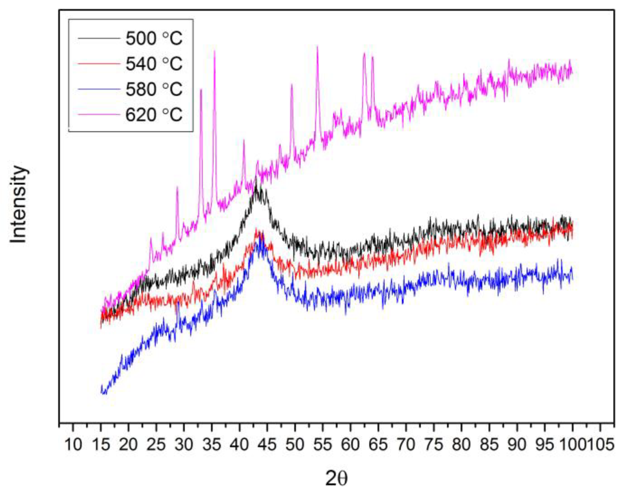
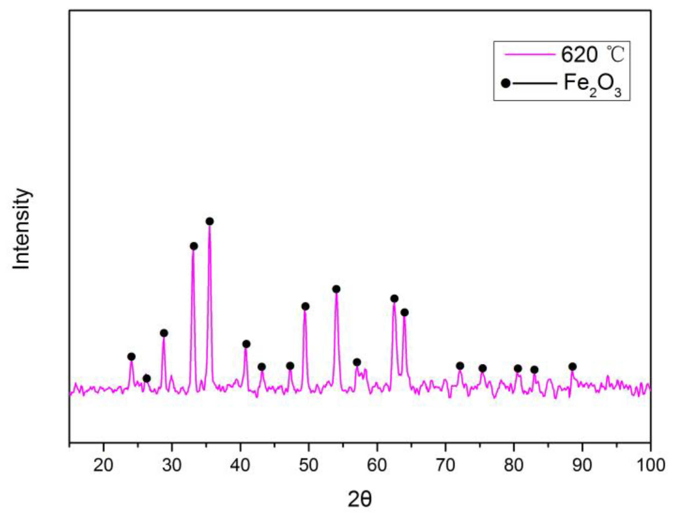
3.3. Effect of Sintering Temperature on Properties of 3D-Printed Fe-Based Metallic Glass Parts

To determine the effect of the sintering temperature on the properties of the 3D-printed Fe-based metallic glass parts, sintering of 3 cm × 3 cm square sheets was performed at 500 °C, 540 °C, 580 °C, and 620 °C with a holding time of 1 h. The changes of the printed parts after sintering are shown in Figure 5. For the sintering temperature of 500 °C, the central part of the sintered parts was undersintered because of the low sintering temperature. For the sintering temperature of 620 °C, more pores were formed on the surface of the sintered parts and bad warpage occurred. For sintering temperatures of 540 °C and 580 °C, the surface quality of the sintered parts was improved.
X-ray diffraction was used to analyze the crystallization degree of the sintered parts at different sintering temperatures using a scanning step size of 0.1° in the 2θ range of 15–100°. The XRD (X-ray diffraction) patterns are presented in Figure 6. For sintering temperatures of 500 °C, 540 °C, and 580 °C, the XRD patterns of the sintered parts consisted of broad and diffuse diffraction peaks, and a broader halo around 43° is observed, indicating that the sintered parts almost were not crystallized [24]. The sintering temperature of 620 °C has long-range periodicity and sharp diffraction peaks between 25° and 70°, indicating that the sintered parts were crystallized. The phase analysis is shown in Figure 7, and illustrates that the crystalline phase was mainly Fe2O3. This is mainly because the crystalline Fe was precipitated with the increased sintering temperature and then reacted with O2.
The microstructures of the sintered parts were examined using scanning electron microscopy. Figure 8 shows the micromorphology of the printed parts sintered at different temperatures at a magnification of 1000 times. With increasing sintering temperature, the sintered parts became denser. For a sintering temperature of 500 °C, more irregular-shaped interspace appeared around the powder particles, and the density was poor. A small part of the powder particles started to contact each other. At a sintering temperature of 540 °C, the small particles began to fuse, forming a sintering neck, and the sintered parts were further densified. However, the contact surface between the particles was smaller, and many small irregular-shaped interspaces were still present around the particles. Upon further increasing the sintering temperature to 580 °C, the small particles fused and grew, forming large particles with irregular shape. A contact interface was formed between the powder particles, and the interspace was reduced while the density increased. At a sintering temperature of 620 °C, small particles fused to form large particles and further sphericized. Small interspaces accumulated to form macropores, with the quantity of interspaces clearly decreasing, and large particles fused and formed blocks. The maximum density of the sintered parts was achieved under this condition; however, the Fe-based metallic glass in the sintered parts was partially crystallized.
For sintering temperatures of 540 °C, 580 °C, and 620 °C, many crumb structures were observed on the surfaces of the Fe-based metallic glass particles. The microscopic morphology of the particle surfaces at higher magnification is shown in Figure 9. Fine grains were formed on the surfaces of the powder particles, and the grain size increased with increasing sintering temperature. The distance between powder particles increased because of this grain growth, and, accordingly, the size of the sintered parts increased from a macroscopic viewpoint. Therefore, the sintered parts expanded, with the level of expansion increasing with increasing sintering temperature.

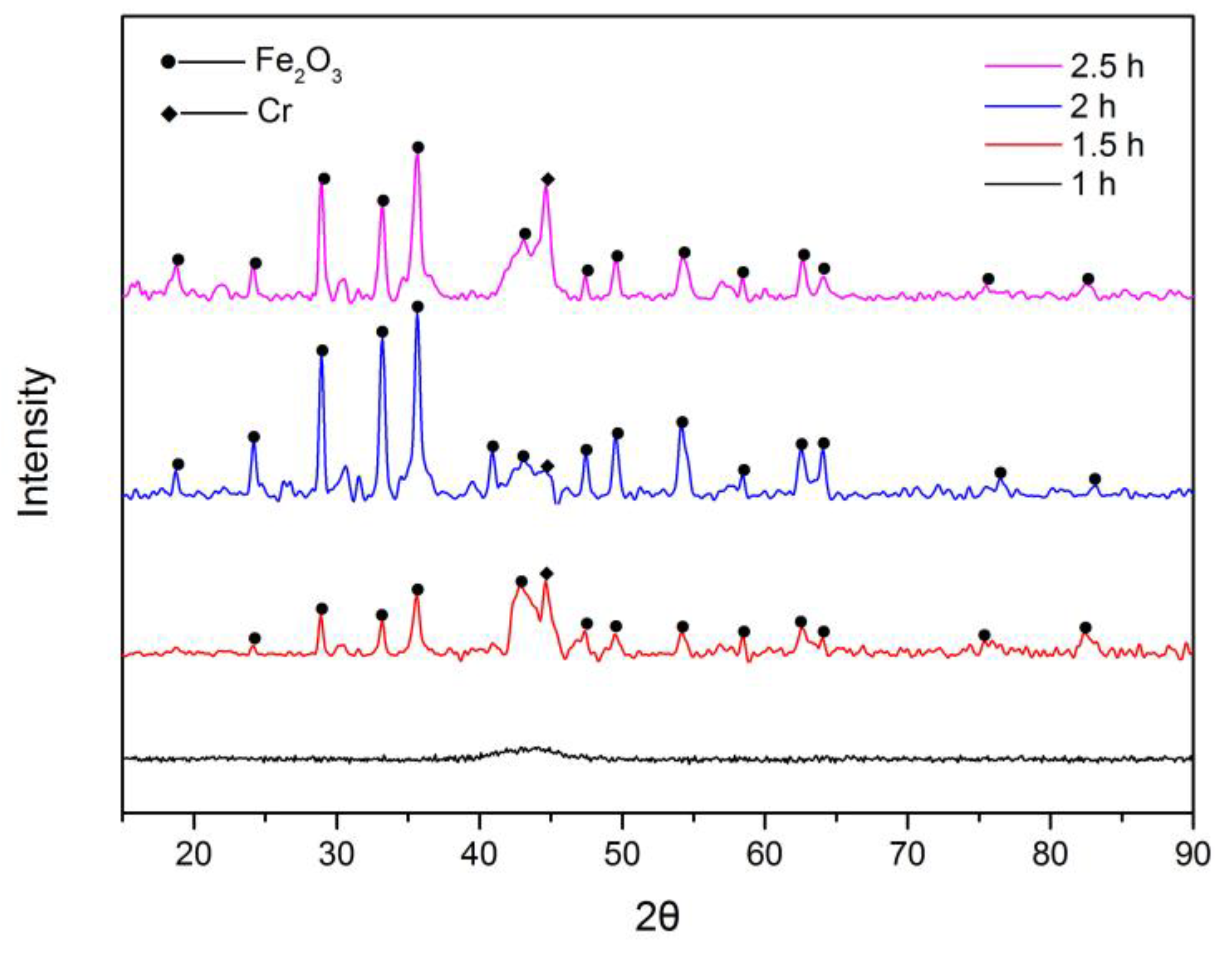
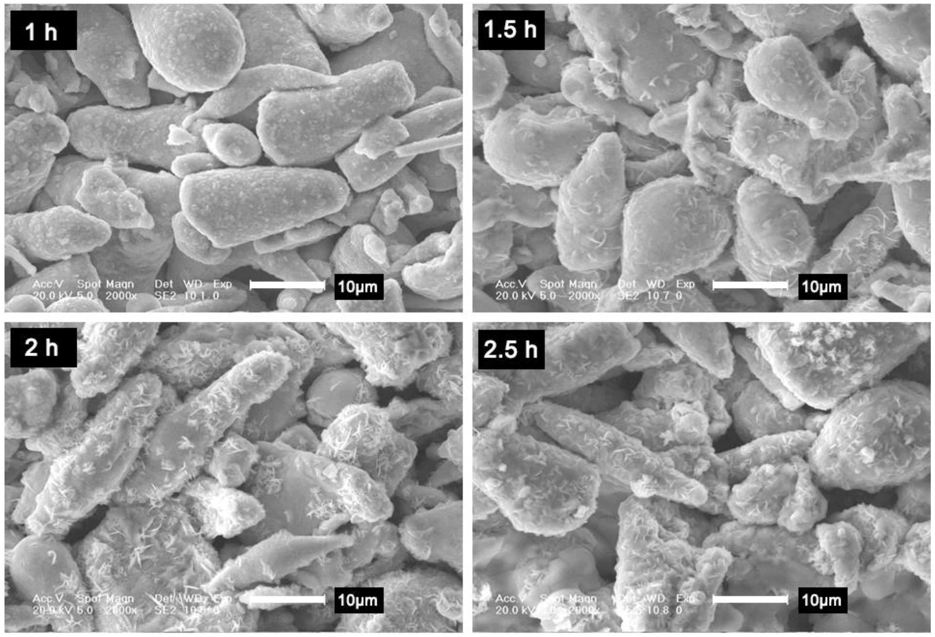
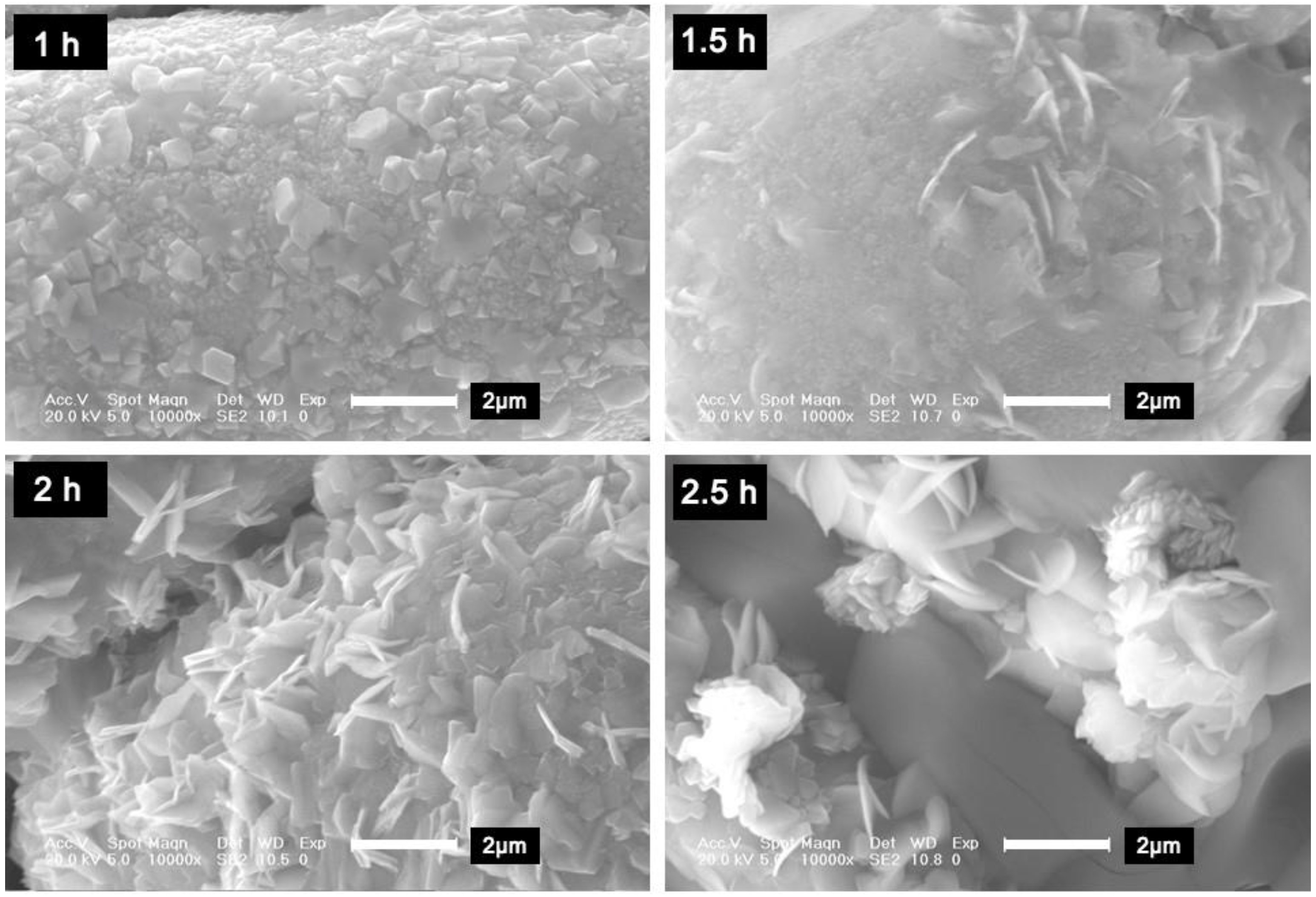
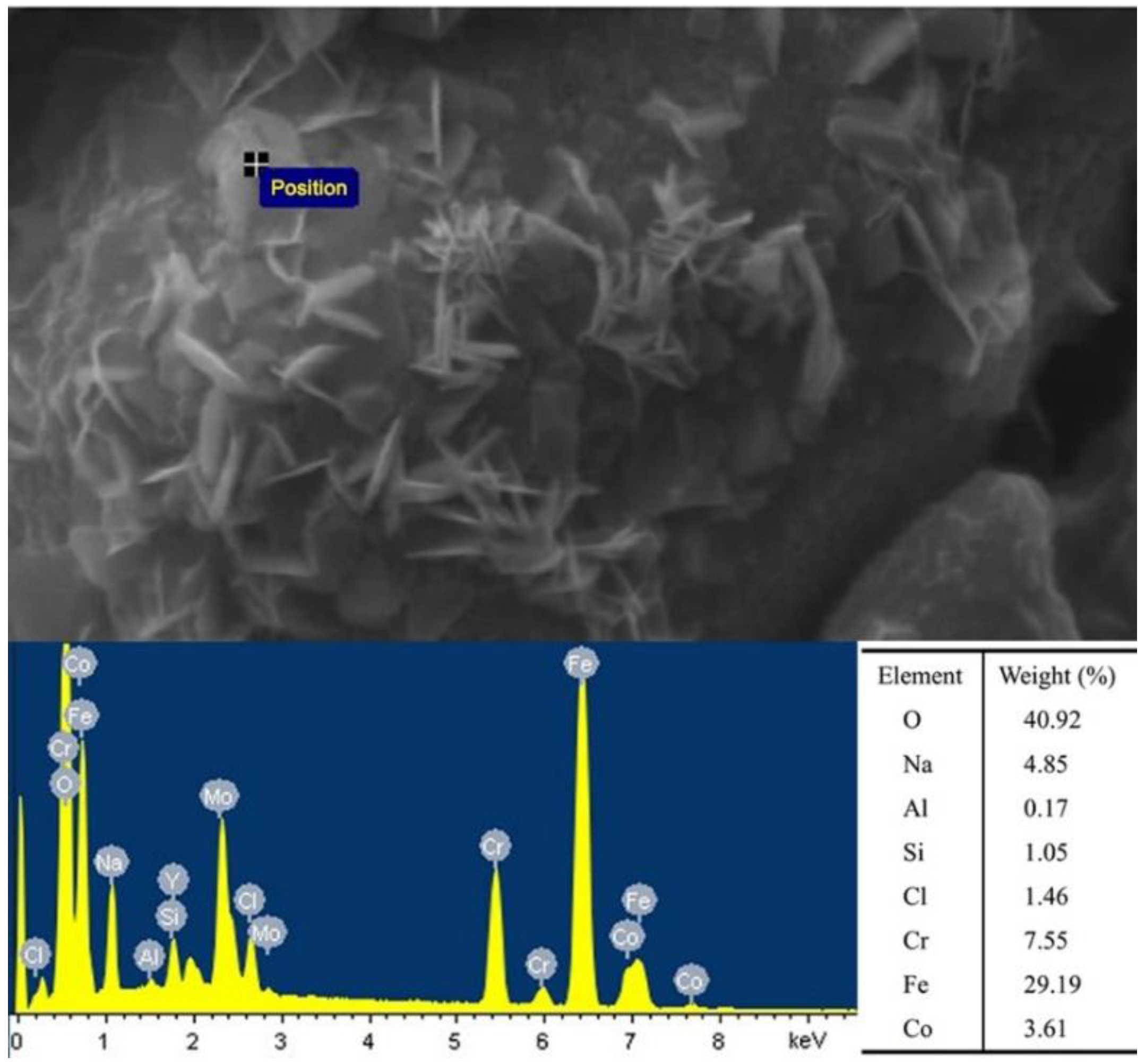
3.4. Effect of Holding Time on Properties of 3D-Printed Fe-Based Metallic Glass Parts

To investigate the effect of the holding time on the properties of the 3D-printed Fe-based metallic glass parts, sintering of 3 cm × 3 cm square sheets was performed at 580 °C for holding times of 1, 1.5, 2, and 2.5 h. The effect of the holding time is shown in Figure 10. For the holding time of 2 h, more pores were observed on the surfaces of the printed parts in addition to slight warpage. For holding times of 1, 1.5, and 2.5 h, the surface quality of the sintered parts was better.
X-ray diffraction was used to analyze the crystallization degree of the sintered parts at different holding times using a scanning step size of 0.1° in the 2θ range of 15–90°. The results are presented in Figure 11. For a holding time of 1 h, the XRD patterns of the sintered parts consisted of broad and diffuse diffraction peaks around 43°, indicating that the Fe-based metallic glass did not crystallize. However, upon increasing the holding time to 1.5, 2, and 2.5 h, some long-range periodicity and sharp diffraction peaks appeared between 15° and 65° in the X-ray diffraction patterns of the sintered parts, indicating that the sintered parts were crystallized. The crystalline phases were mainly Fe2O3 and Cr. Therefore, for a sintering temperature of 580 °C, the holding time should be less than 1.5 h to avoid crystallization.
The microstructures of the sintered parts for different holding times were examined using scanning electron microscopy. The microstructures of the sintered parts at a magnification of 2000 times for different holding times are shown in Figure 12. With increasing holding time, the distance between powder particles decreased, and small particles fused to form irregular large particles. Interface contact between the particles began to form; however, large particles did not fuse with each other to form blocks. Many small interspaces appeared around the particles. The density was less than that of the sintered parts prepared at a sintering temperature of 620 °C with a holding time of 1 h. The holding time had less of an effect on the densification of the sintered parts than did the sintering temperature. To obtain sintered parts with high density, both the sintering temperature and holding time should be increased while avoiding crystallization of the Fe-based metallic glass.
After sintering at the four holding times, the surfaces of the Fe-based metallic glass particles consisted of many crumb structures. The microscopic appearance of the particles’ surfaces under further magnification is shown in Figure 13. Fine grains were formed on the surfaces of the powder particles, and with increasing holding time, the grains became thin sheets and the number of grains increased. In addition, because of the grain growth, the distance between the powder particles increased, and the size of the sintered parts increased from a macroscopic viewpoint. Therefore, the sizes of the sintered parts increased. Figure 14 shows the energy dispersive spectrometry of the grains on the particle surface, which illustrated that Fe, Cr, and O elements were the key components. Since Figure 11 presented that the crystalline phases of the sintered parts were mainly Fe2O3 and Cr, the grains should be Fe2O3 and Cr crystals.

4. Conclusions

In this study, the pneumatic injection manufacturing system shows better printing accuracy. The sintering temperature was observed to have a larger effect on the properties of the sintered parts than the holding time. Optimal surface quality was achieved for a sintering temperature of 580 °C and holding time of 1 h. The Fe-based metallic glass powder prepared under these conditions did not crystallize, and density was improved. However, the strength of the sintered parts was low, and the sintering temperature and holding time during sintering require additional tuning to further improve the density and strength of the sintered parts. The results of this study demonstrate the feasibility of forming and sintering Fe-based metallic glass printed parts using pneumatic injection additive manufacture, which will promote the further application of Fe-based metallic glass in various fields.

Author Contributions

W.W. proposed the key idea of this paper. W.L. and H.D. carried out the experiments. W.W. and G.L. analyzed the data, and wrote and modified the manuscript. B.W. discussed the experimental data and improved figures. B.S. and S.Z. assisted with discussing the idea and results. J.Z. reviewed the manuscript. All authors had a hand in the final manuscript.

Funding

This research is supported by National Natural Science Foundation of China (No. 51675226), Key Scientific and Technological Research Project of Jilin Province (No. 20180201055GX), Project of International Science and Technology Cooperation of Jilin Province (No. 20170414043GH), and Graduate Innovation Fund of Jilin University (No. 2017143).

Acknowledgments

We thank Hao Jiang, from our group, for editing the references of this manuscript.

Conflicts of Interest

The authors declare no conflict of interest.

References

  1. Gu, X.J.; Poon, S.J.; Shiflet, G.J. Mechanical properties of iron-based bulk metallic glasses. J. Mater. Res. 2011, 22, 344–351. [Google Scholar] [CrossRef]
  2. Suryanarayana, C.; Inoue, A. Iron-based bulk metallic glasses. Int. Mater. Rev. 2013, 58, 131–166. [Google Scholar] [CrossRef] [Green Version]
  3. Ghidelli, M.; Idrissi, H.; Gravier, S.; Blandin, J.-J.; Raskin, J.-P.; Schryvers, D.; Pardoen, T. Homogeneous flow and size dependent mechanical behavior in highly ductile Zr 65 Ni 35 metallic glass films. Acta Mater. 2017, 131, 246–259. [Google Scholar] [CrossRef]
  4. Wu, Y.; Li, H.X.; Gao, J.E.; Wang, H.; Liu, X.J.; Miller, M.K.; Bei, H.; Gao, Y.F.; Lu, Z.P. Nanocrystallization in a cu-doped fe-based metallic glass. J. Alloys Compd. 2016, 688, 822–827. [Google Scholar] [CrossRef]
  5. Schroers, J. Processing of bulk metallic glass. Adv. Mater. 2010, 22, 1566–1597. [Google Scholar] [CrossRef] [PubMed]
  6. Pauly, S.; Löber, L.; Petters, R.; Stoica, M.; Scudino, S.; Kühn, U.; Eckert, J. Processing metallic glasses by selective laser melting. Mater. Today 2013, 16, 37–41. [Google Scholar] [CrossRef]
  7. Williams, E.; Lavery, N. Laser processing of bulk metallic glass: A review. J. Mater. Process. Technol. 2017, 247, 73–91. [Google Scholar] [CrossRef]
  8. Jung, H.Y.; Choi, S.J.; Prashanth, K.G.; Stoica, M.; Scudino, S.; Yi, S.; Kühn, U.; Kim, D.H.; Kim, K.B.; Eckert, J. Fabrication of Fe-based bulk metallic glass by selective laser melting: A parameter study. Mater. Des. 2015, 86, 703–708. [Google Scholar] [CrossRef]
  9. Li, N.; Zhang, J.; Xing, W.; Ouyang, D.; Liu, L. 3D printing of Fe-based bulk metallic glass composites with combined high strength and fracture toughness. Mater. Des. 2018, 143, 285–296. [Google Scholar] [CrossRef]
  10. Cesarano, J., III; Segalman, R.; Calvert, P. Robocasting provides moldless fabrication from slurry deposition. Ceram. Ind. 1998, 148, 94–102. [Google Scholar]
  11. Lewis, J.A. Direct ink writing of 3D functional materials. Adv. Funct. Mater. 2006, 16, 2193–2204. [Google Scholar] [CrossRef]
  12. Zhu, D.B.; Xu, A.P. Dual-phase materials extrusion process for rapid fabrication of ceramic dental crown. Adv. Mater. Res. 2010, 97–101, 4050–4053. [Google Scholar] [CrossRef]
  13. Hong, S.; Sanchez, C.; Du, H.; Kim, N. Fabrication of 3D printed metal structures by use of high-viscosity cu paste and a screw extruder. J. Electr. Mater. 2015, 44, 836–841. [Google Scholar] [CrossRef]
  14. Li, Y.; Li, L.; Li, B. Direct ink writing of three-dimensional (K, Na)NbO3-based piezoelectric ceramics. Materials 2015, 8, 1729–1737. [Google Scholar] [CrossRef] [PubMed]
  15. Ren, X.; Shao, H.; Lin, T.; Zheng, H. 3D gel-printing—An additive manufacturing method for producing complex shape parts. Mater. Des. 2016, 101, 80–87. [Google Scholar] [CrossRef]
  16. Morissette, S.L.; Lewis, J.A.; Cesarano Iii, J.; Dimos, D.B.; Baer, T.; Hackley, V.A. Solid freeform fabrication of aqueous alumina-poly(vinyl alcohol) gelcasting suspensions. J. Am. Ceram. Soc. 2000, 83, 2409. [Google Scholar] [CrossRef]
  17. Wu, W.; Du, H.; Sui, H.; Guo, X.; Wang, B.; Li, G.; Zhao, J. Printing parameters and strengthening mechanism of pneumatic injection additive manufacturing with iron powder slurry. Int. J. Adv. Manuf. Technol. 2017, 94, 3809–3817. [Google Scholar] [CrossRef]
  18. Fu, K.; Wang, Y.; Yan, C.; Yao, Y.; Chen, Y.; Dai, J.; Lacey, S.; Wang, Y.; Wan, J.; Li, T.; et al. Graphene oxide-based electrode inks for 3D-printed lithium-ion batteries. Adv. Mater. 2016, 28, 2587–2594. [Google Scholar] [CrossRef] [PubMed]
  19. Jain, R.A. The manufacturing techniques of various drug loaded biodegradable poly(lactide-co-glycolide) (plga) devices. Biomaterials 2000, 21, 2475–2490. [Google Scholar] [CrossRef]
  20. Jakus, A.E.; Secor, E.B.; Rutz, A.L.; Jordan, S.W.; Hersam, M.C.; Shah, R.N. Three-dimensional printing of high-content graphene scaffolds for electronic and biomedical applications. ACS Nano 2015, 9, 4636–4648. [Google Scholar] [CrossRef] [PubMed]
  21. He, Y.; Yang, F.; Zhao, H.; Gao, Q.; Xia, B.; Fu, J. Research on the printability of hydrogels in 3D bioprinting. Sci. Rep. 2016, 6, 29977. [Google Scholar] [CrossRef] [PubMed] [Green Version]
  22. Jakus, A.E.; Taylor, S.L.; Geisendorfer, N.R.; Dunand, D.C.; Shah, R.N. Metallic printing: Metallic architectures from 3D-printed powder-based liquid inks (adv. Funct. Mater. 45/2015). Adv. Funct. Mater. 2015, 25, 7099. [Google Scholar] [CrossRef]
  23. Wu, W.; Du, H.; Sui, H.; Sun, B.; Wang, B.; Yu, Z.; Ni, H.; Li, G.; Zhao, J. Study of printing parameters of pneumatic-injection 3D printing of Fe-based metallic glass. J. Non-Cryst. Solids 2018, 489, 50–56. [Google Scholar] [CrossRef]
  24. Ghidelli, M.; Gravier, S.; Blandin, J.-J.; Pardoen, T.; Raskin, J.-P.; Mompiou, F. Compositional-induced structural change in ZrxNi100−x thin film metallic glasses. J. Alloys Compd. 2014, 615, S348–S351. [Google Scholar] [CrossRef]
Figure 1. Thermogravimetric analysis.
Metals 08 00429 g001
Figure 2. (a) 3D-printed Fe-based metallic glass part, reconstructed 3D models of (b) printed part and (c) sintered part.
Metals 08 00429 g002
Figure 3. Deformation analysis of (a) printed part and (b) sintered part.
Metals 08 00429 g003
Figure 4. DSC curve of Fe-based metallic glass.
Metals 08 00429 g004
Figure 5. Comparison of printed parts before and after sintering at different sintering temperatures.
Metals 08 00429 g005
Figure 6. XRD patterns of sintered parts prepared at different sintering temperatures.
Metals 08 00429 g006
Figure 7. Phase analysis of sintered parts prepared at 620 °C.
Metals 08 00429 g007
Figure 8. SEM images of parts sintered at different temperatures (magnified 1000 times).
Metals 08 00429 g008
Figure 9. SEM images of parts sintered at different temperatures (magnified 10,000 times).
Metals 08 00429 g009
Figure 10. Comparison of printed parts before and after sintering for different holding times.
Metals 08 00429 g010
Figure 11. XRD patterns of sintered parts for different holding times.
Metals 08 00429 g011
Figure 12. SEM images of sintered parts for different holding times (magnified 2000 times).
Metals 08 00429 g012
Figure 13. SEM images of parts sintered at holding times (magnified 10,000 times).
Metals 08 00429 g013
Figure 14. Energy dispersive spectrometry of the grains on the particle surface.
Metals 08 00429 g014

