Characterization of In-Situ TiB/TiC Particle-Reinforced Ti-5Al-5Mo-5V-3Cr Matrix Composites Synthesized by Solid-State Reaction with B4C and Graphite through SPS

Abstract
:
1. Introduction
2. Materials and Methods
3. Results and Discussion
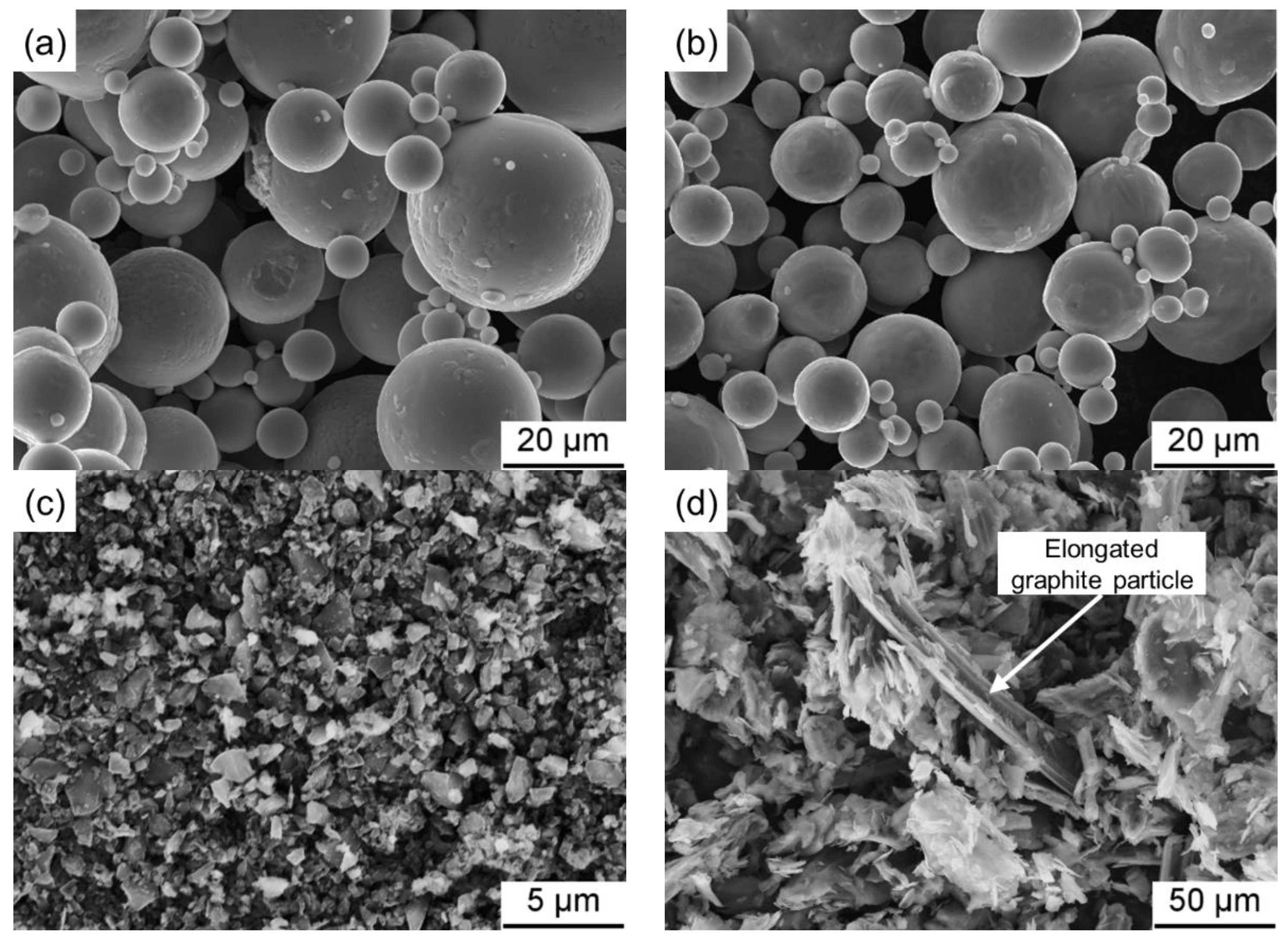
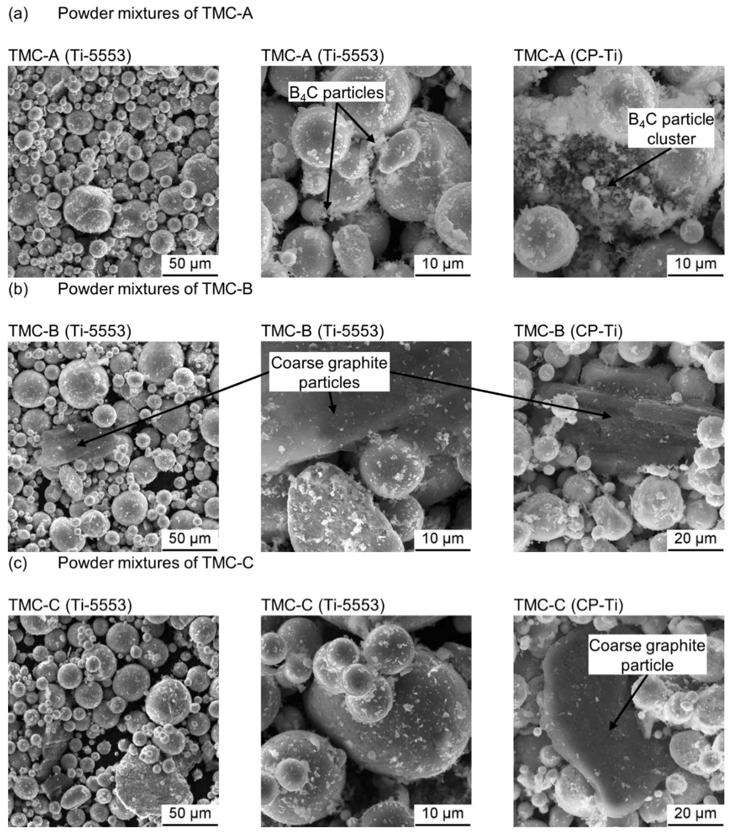
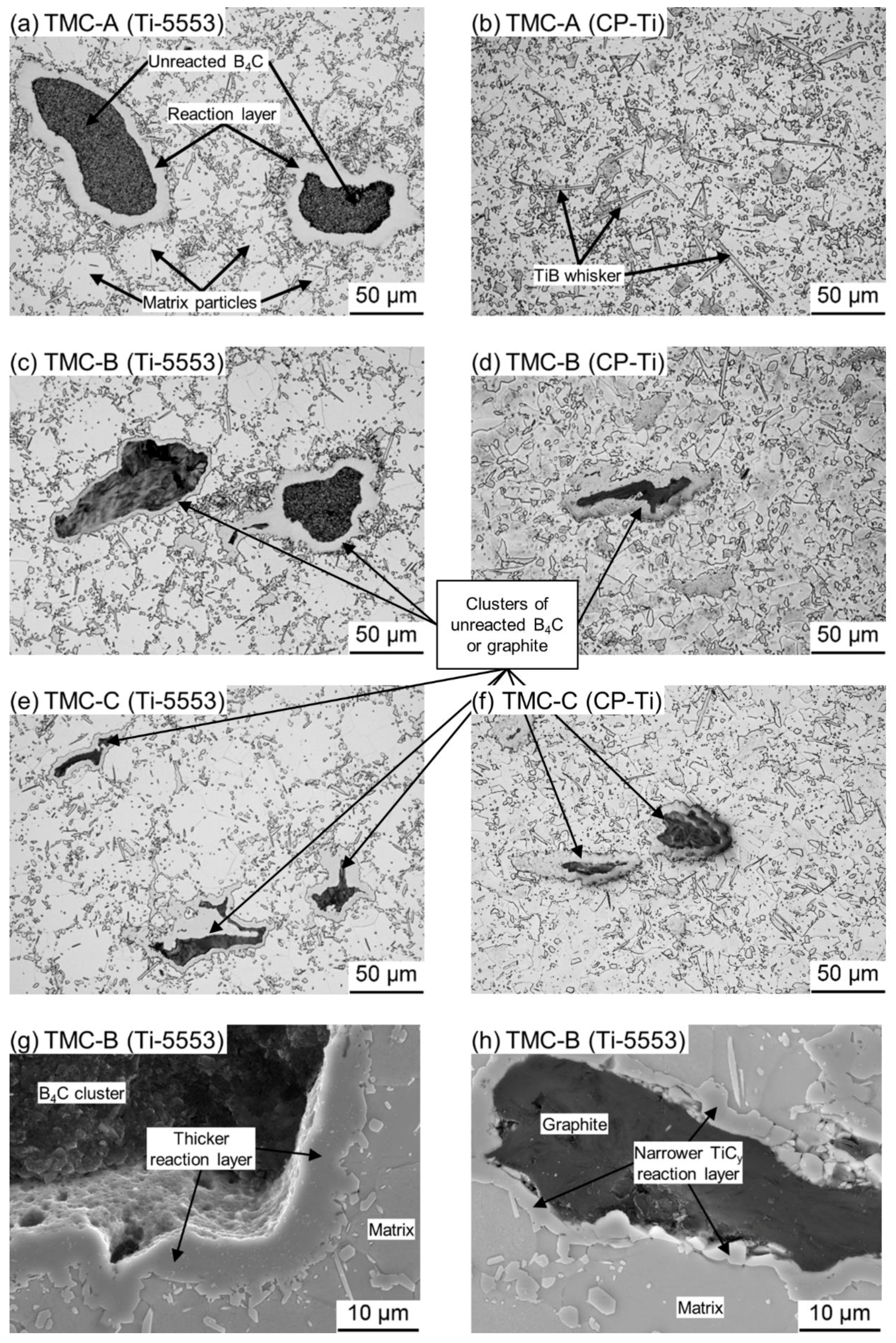
3.1. Structural Characterization
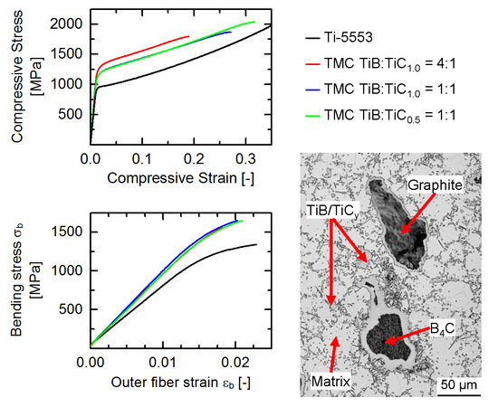
3.2. Mechanical Properties of the Ti-5553-Based TMCs
4. Conclusions
Author Contributions
Funding
Acknowledgments
Conflicts of Interest
References
- Yang, Z.F.; Lu, W.J.; Xu, D.; Qin, J.N.; Zhang, D. In situ synthesis of hybrid and multiple-dimensioned titanium matrix composites. J. Alloys Compd. 2006, 419, 76–80. [Google Scholar] [CrossRef]
- Yanbin, L.; Yong, L.; Huiping, T.; Bin, W.; Bin, L. Fabrication and mechanical properties of in situ TiC/Ti metal matrix composites. J. Alloys Compd. 2011, 509, 3592–3601. [Google Scholar] [CrossRef]
- Gorsse, S.; Miracle, D. Mechanical properties of Ti-6Al-4V/TiB composites with randomly oriented and aligned TiB reinforcements. Acta Mater. 2003, 51, 2427–2442. [Google Scholar] [CrossRef]
- Huang, L.J.; Geng, L.; Xu, H.Y.; Peng, H.X. In situ TiC particles reinforced Ti6Al4V matrix composite with a network reinforcement architecture. Mater. Sci. Eng. A 2011, 528, 2859–2862. [Google Scholar] [CrossRef]
- Tjong, S.; Ma, Z.Y. Microstructural and mechanical characteristics of in situ metal matrix composites. Mater. Sci. Eng. R 2000, 29, 49–113. [Google Scholar] [CrossRef]
- Carman, A.; Zhang, L.C.; Ivasishin, O.M.; Savvakin, D.G.; Matviychuk, M.V.; Pereloma, E.V. Role of alloying elements in microstructure evolution and alloying elements behaviour during sintering of a near-β titanium alloy. Mater. Sci. Eng. A 2011, 528, 1686–1693. [Google Scholar] [CrossRef]
- Feng, H.; Zhou, Y.; Jia, D.; Meng, Q.; Rao, J. Growth mechanism of in situ TiB whiskers in spark plasma sintered TiB/Ti metal matrix composites. Cryst. Growth Des. 2006, 6, 1626–1630. [Google Scholar] [CrossRef]
- Ni, D.R.; Geng, L.; Zhang, J.; Zheng, Z.Z. Effect of B4C particle size on microstructure of in situ titanium matrix composites prepared by reactive processing of Ti-B4C system. Scr. Mater. 2006, 55, 429–432. [Google Scholar] [CrossRef]
- Soboyejo, W.O.; Lederich, R.J.; Sastry, S. Mechanical behavior of damage tolerant TiB whisker-reinforced in situ titanium matrix composites. Acta Metall. Mater. 1994, 42, 2579–2591. [Google Scholar] [CrossRef]
- Ma, Z.Y.; Tjong, S.C.; Gen, L. In-situ Ti-TiB metal-matrix composite prepared by a reactive pressing process. Scr. Mater. 2000, 42, 367–373. [Google Scholar] [CrossRef]
- Tjong, S.C.; Mai, Y.-W. Processing-structure-property aspects of particulate- and whisker-reinforced titanium matrix composites. Compos. Sci. Technol. 2008, 68, 583–601. [Google Scholar] [CrossRef]
- Atri, R.; Ravichandran, K.; Jha, S. Elastic properties of in-situ processed Ti-TiB composites measured by impulse excitation of vibration. Mater. Sci. Eng. A 1999, 271, 150–159. [Google Scholar] [CrossRef]
- Zhang, J.; Ke, W.; Ji, W.; Fan, Z.; Wang, W.; Fu, Z. Microstructure and properties of insitu titanium boride (TiB)/titanium (Ti) composites. Mater. Sci. Eng. A 2015, 648, 158–163. [Google Scholar] [CrossRef]
- Jimoh, A.; Sigalas, I.; Hermann, M. In situ synthesis of titanium matrix composite (Ti-TiB-TiC) through sintering of TiH2-B4C. Mater. Sci. Appl. 2012, 3, 30–35. [Google Scholar] [CrossRef]
- Alman, D.; Hawk, J. The abrasive wear of sintered titanium matrix–ceramic particle reinforced composites. Wear 1999, 225–229, 629–639. [Google Scholar] [CrossRef]
- Kim, I.Y.; Choi, B.J.; Kim, Y.J.; Lee, Y.Z. Friction and wear behavior of titanium matrix (TiB + TiC) composites. Wear 2011, 271, 1962–1965. [Google Scholar] [CrossRef]
- AlMangour, B.; Grzesiak, D.; Yang, J.-M. In situ formation of TiC-particle-reinforced stainless steel matrix nanocomposites during ball milling: Feedstock powder preparation for selective laser melting at various energy densities. Powder Technol. 2018, 326, 467–478. [Google Scholar] [CrossRef]
- Wu, C.L.; Zhang, S.; Zhang, C.H.; Zhang, J.B.; Liu, Y. Formation mechanism and phase evolution of in situ synthesizing TiC-reinforced 316L stainless steel matrix composites by laser melting deposition. Mater. Lett. 2018, 217, 304–307. [Google Scholar] [CrossRef]
- Brodkin, D.; Kalidindi, S.R.; Barsoum, M.W.; Zavaliangos, A. Microstructural evolution during transient plastic phase processing of titanium carbide-titanium boride composites. J. Am. Ceram. Soc. 1996, 79, 1945–1952. [Google Scholar] [CrossRef]
- Mogilevsky, P.; Gutmanas, E.Y.; Gotman, I.; Telle, R. Reactive formation of coatings at boron carbide interface with Ti and Cr powders. J. Eur. Ceram. Soc. 1995, 15, 527–535. [Google Scholar] [CrossRef]
- Zhao, H.; Cheng, Y.-B. Formation of TiB2-TiC composites by reactive sintering. Ceram. Int. 1999, 25, 353–358. [Google Scholar] [CrossRef]
- Vallauri, D.; Atías Adrián, I.C.; Chrysanthou, A. TiC-TiB2 composites: A review of phase relationships, processing and properties. J. Eur. Ceram. Soc. 2008, 28, 1697–1713. [Google Scholar] [CrossRef]
- Quinn, C.J.; Kohlstedt, D.L. Solid-state reaction between titanium carbide and titanium metal. J. Am. Ceram. Soc. 1984, 67, 305–310. [Google Scholar] [CrossRef]
- Choi, Y.; Rhee, S.-W. Equilibrium in the reaction of Ti and C to form substoichiometric TiCx. J. Mater. Sci. Lett. 1994, 13, 323–325. [Google Scholar] [CrossRef]
- Storms, E.K. (Ed.) Refractory Materilas: The Refractory Carbides; Academic Press: New York, NY, USA, 1967; Volume 2. [Google Scholar]
- Okamoto, H. C-Ti (Carbon-Titanium). J. Phase Equilib. Diffus. 1998, 19, 89. [Google Scholar] [CrossRef]
- AlMangour, B.; Grzesiak, D.; Yang, J.-M. In-situ formation of novel TiC-particle-reinforced 316L stainless steel bulk-form composites by selective laser melting. J. Alloys Compd. 2017, 706, 409–418. [Google Scholar] [CrossRef]
- Lu, W.J.; Zhang, D.; Zhang, X.N.; Wu, R.J.; Sakata, T.; Mori, H. Microstructure and tensile properties of in situ (TiB + TiC)/Ti6242 (TiB:TiC = 1:1) composites prepared by common casting technique. Mater. Sci. Eng. A 2001, 311, 142–150. [Google Scholar] [CrossRef]
- Wang, M.-M.; Lu, W.-J.; Qin, J.; Ma, F.; Lu, J.; Zhang, D. Effect of volume fraction of reinforcement on room temperature tensile property of in situ (TiB + TiC)/Ti matrix composites. Mater. Des. 2006, 27, 494–498. [Google Scholar] [CrossRef]
- Grützner, S.; Krüger, L.; Schimpf, C.; Radajewski, M.; Schneider, I. Microstructure and mechanical properties of in-situ TiB/TiC particle-reinforced Ti-5Al-5Mo-5V-3Cr composites synthesized by spark plasma sintering. Metall. Mater. Trans. A 2018. under review. [Google Scholar]
- Young, R. The Rietveld Method; Monographs on Crystallography 5; Oxford University Press: Oxford, UK, 2002; p. 298. ISBN 9780198559122. [Google Scholar]
- Lutterotti, L.; Matthies, S.; Wenk, H.R. MAUD: A friendly Java program for material analysis using diffraction. Newslett. CPD 1999, 21, 14–15. [Google Scholar]
- Hayun, S.; Kalabukhov, S.; Ezersky, V.; Dariel, M.P.; Frage, N. Microstructural characterization of spark plasma sintered boron carbide ceramics. Ceram. Int. 2010, 36, 451–457. [Google Scholar] [CrossRef]
- Vansant, C.A.; Phelps, W.C. Carbide formation from beta-titanium and graphite. Trans. ASM Q 1966, 59, 105–112. [Google Scholar]
- Loo, F.J.J.; Bastin, G.F. On the diffusion of carbon in titanium carbide. Metall. Trans. A 1989, 20, 403–411. [Google Scholar] [CrossRef]
- Dariel, M.P. Enhanced Mass Transport in Titanium Carbide at Large Departures from Stoichiometry. Powder Metall. Met. Ceram. 2003, 42, 460–467. [Google Scholar] [CrossRef]
- Wittmann, A.; Nowotny, H.; Boller, H. Ein Beitrag zum Dreistoff Titan-Molybdän-Bor. Monatsh. Chem. Verwandte Teile And. Wiss. 1960, 91, 608–615. [Google Scholar] [CrossRef]
- Enomoto, M. The B-Ti-V system. J. Phase Equilib. 1992, 13, 641–644. [Google Scholar] [CrossRef]
- Zdaniewski, W.A. Solid solubility effect on properties of titanium diboride. J. Am. Ceram. Soc. 1987, 70, 793–797. [Google Scholar] [CrossRef]
- Schmidt, H.; Borchardt, G.; Schmalzried, C.; Telle, R.; Weber, S.; Scherrer, H. Self-diffusion of boron in TiB2. J. Appl. Phys. 2003, 93, 907–911. [Google Scholar] [CrossRef]
- Ehrlich, P. Über die binären Systeme des Titans mit den Elementen Stickstoff, Kohlenstoff, Bor und Beryllium. Z. Anorg. Chem. 1949, 259, 1–41. [Google Scholar] [CrossRef]
- Hubbard, C.R. Standard X-ray Diffraction Powder Patterns: Section 18—Data for 58 Substances; Monogram 25—Section 18; National Bureau of Standards: Washington, DC, USA, 1981; Volume 18.
- Lin, Y.; Zee, R.H.; Chin, B.A. In situ formation of three-dimensional TiC reinforcements in Ti-TiC composites. Metall. Mater. Trans. A 1991, 22, 859–865. [Google Scholar] [CrossRef]
- Zarrinfar, N.; Shipway, P.H.; Kennedy, A.R.; Saidi, A. Carbide stoichiometry in TiCx and Cu–TiCx produced by self-propagating high-temperature synthesis. Scr. Mater. 2002, 46, 121–126. [Google Scholar] [CrossRef]
- Chandran, K.S.R.; Panda, K.B.; Sahay, S.S. TiBw-Reinforced Ti Composites: Processing, Properties, Application Prospects, and Research Needs. JOM J. Miner. Met. Mater. Soc. 2004, 56, 42–48. [Google Scholar] [CrossRef]
- Lipatnikov, V.N.; Rempel, A.A.; Gusev, A.I. Atomic ordering and hardness of nonstoichiometric titanium carbide. Wear Resist. Mater. S. Afr. Ind. 1997, 15, 61–64. [Google Scholar] [CrossRef]
- Sundgren, J.-E.; Johansson, B.-O.; Karlsson, S.-E.; Hentzell, H. Mechanisms of reactive sputtering of titanium nitride and titanium carbide II: Morphology and structure. Thin Solid Films 1983, 105, 367–384. [Google Scholar] [CrossRef]


| Temperature in °C | C/Ti Ratio y in TiCy | |
|---|---|---|
| Interface β-Ti/TiCy | Interface TiCy/C | |
| 920 | 0.56 | 0.97 |
| 1200 | 0.53 | 0.97 |
| 1646 | 0.47 | 0.97 |
| Ti-5553 | ||||||||
| Composition | Ti | Al | Mo | V | Cr | Fe | O | N |
| wt.-% | bal. | 5.22 | 5.08 | 4.97 | 2.86 | 0.30 | 0.14 | 0.013 |
| CP-Ti | ||||||||
| Composition | Ti | Fe | N | O | C | - | ||
| wt.-% | bal. | 0.069 | 0.008 | 0.068 | 0.007 | |||
| B4C | ||||||||
| Composition | B | C | N | O | Si | Al | Fe | - |
| wt.-% | bal. | 21.90 | 0.20 | 1.40 | 0.11 | 0.01 | <0.01 | |
| Values in µm | d10 | d50 | d90 |
|---|---|---|---|
| Ti-5553 | 11.12 | 26.56 | 42.64 |
| CP-Ti | 11.83 | 24.97 | 41.27 |
| B4C | 0.51 | 1.08 | 1.96 |
| Graphite 1 | 7.73 | 32.31 | 82.99 |
| Theoretical Reaction Equation | Theoretical Total Ceramic Content | Reactive Powder Addition | Theoretical Molar TiB:TiCy Ratio | TMC Designation |
|---|---|---|---|---|
| (x + 5)Ti + B4C → xTi + 4TiB + TiC1.0 | 12 vol.-% | 4.0 vol.-% B4C | TiB:TiC1.0 = 4:1 | TMC-A (Ti-5553) TMC-A (CP-Ti) |
| (x + 8)Ti + B4C + 3C → xTi + 4TiB + 4TiC1.0 | 12 vol.-% | 2.5 vol.-% B4C 1.8 vol.-% C | TiB:TiC1.0 = 1:1 | TMC-B (Ti-5553) TMC-B (CP-Ti) |
| (x + 8)Ti + B4C + C → xTi + 4TiB + 4TiC0.5 | 12 vol.-% | 2.6 vol.-% B4C 0.6 vol.-% C | TiB:TiC0.5 = 1:1 | TMC-C (Ti-5553) TMC-C (CP-Ti) |
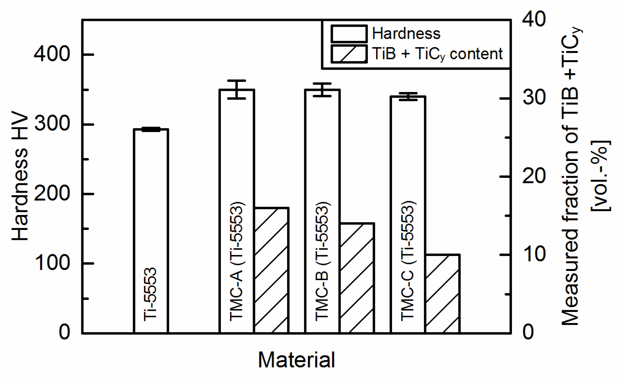
| Material | Ti-bcc | Ti-hcp | TiB | TiCy | TiB + TiC |
|---|---|---|---|---|---|
| vol.-% | |||||
| TMC-A (Ti-5553) | 84 | - | 12 | 4 | 16 |
| TMC-A (CP-Ti) | - | 87 | 10 | 3 | 13 |
| TMC-B (Ti-5553) | 86 | - | 7 | 7 | 14 |
| TMC-B (CP-Ti) | - | 85 | 7 | 8 | 15 |
| TMC-C (Ti-5553) | 90 | - | 6 | 4 | 10 |
| TMC-C (CP-Ti) | - | 87 | 8 | 5 | 13 |
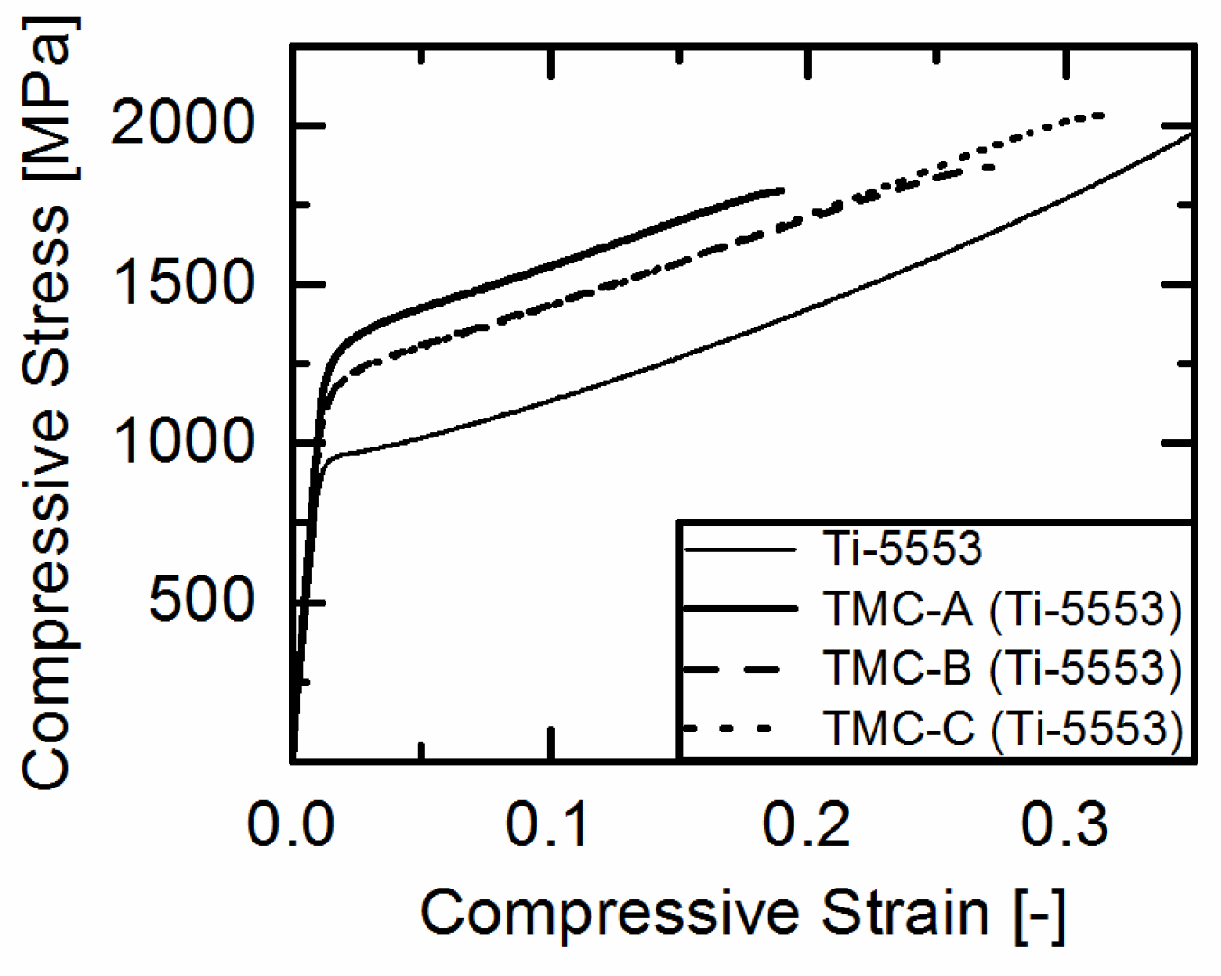
| Material | σd0.2 | σdf | εdf |
|---|---|---|---|
| MPa | MPa | % | |
| Ti-5553 | 920 ± 20 | 1 | 1 |
| TMC-A (Ti-5553) | 1190 ± 30 | 1780 ± 30 | 17.7 ± 1.1 |
| TMC-B (Ti-5553) | 1110 ± 10 | 1910 ± 60 | 26.7 ± 2.1 |
| TMC-C (Ti-5553) | 1130 ± 10 | 2000 ± 10 | 27.8 ± 2.2 |
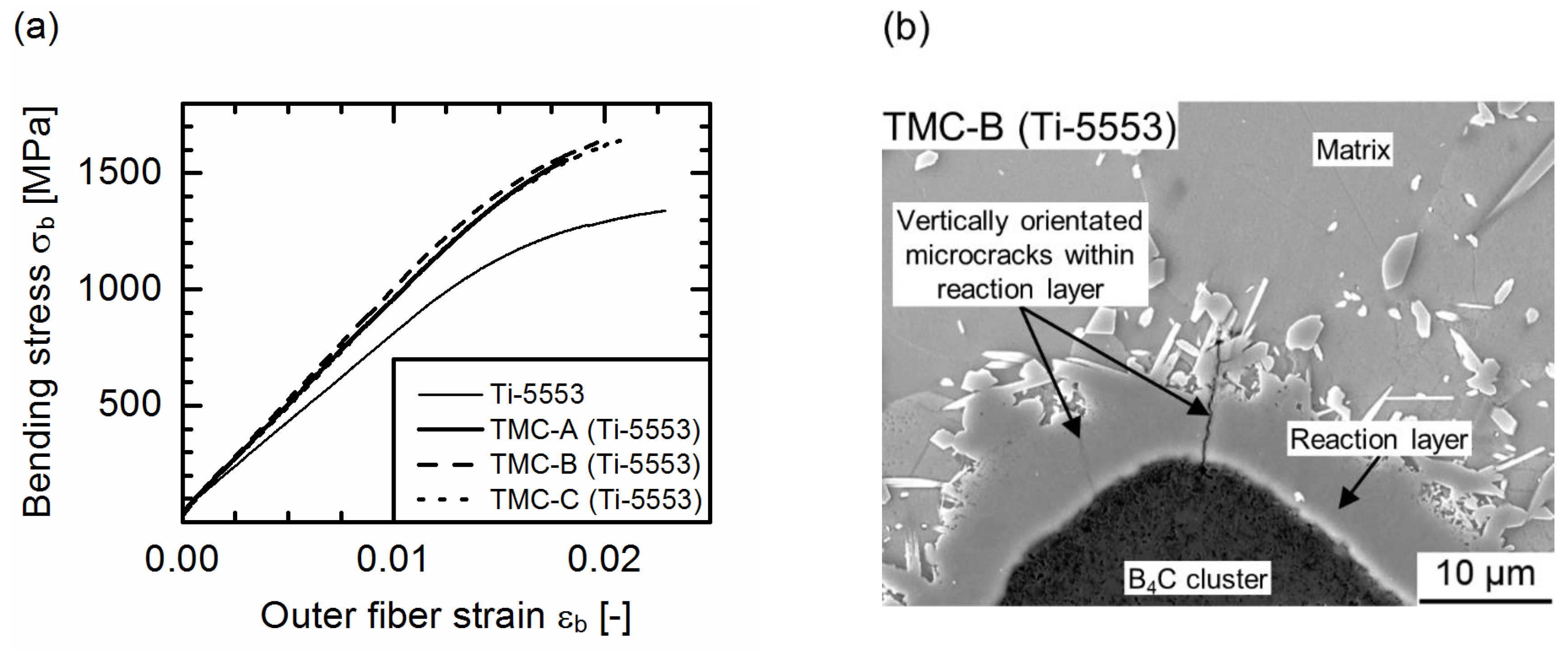
| Material | σbf | εbf | Eb |
|---|---|---|---|
| MPa | % | GPa | |
| Ti-5553 | 1360 ± 30 | 2.4 ± 0.16 | 86 ± 8 |
| TMC-A (Ti-5553) | 1540 ± 20 | 1.8 ± 0.04 | 100 ± 4 |
| TMC-B (Ti-5553) | 1630 ± 40 | 2.45 ± 0.45 | 99 ± 7 |
| TMC-C (Ti-5553) | 1620 ± 40 | 2.12 ± 0.04 | 96 ± 3 |
© 2018 by the authors. Licensee MDPI, Basel, Switzerland. This article is an open access article distributed under the terms and conditions of the Creative Commons Attribution (CC BY) license (http://creativecommons.org/licenses/by/4.0/).
Share and Cite
Grützner, S.; Krüger, L.; Radajewski, M.; Schneider, I. Characterization of In-Situ TiB/TiC Particle-Reinforced Ti-5Al-5Mo-5V-3Cr Matrix Composites Synthesized by Solid-State Reaction with B4C and Graphite through SPS. Metals 2018, 8, 377. https://doi.org/10.3390/met8060377
Grützner S, Krüger L, Radajewski M, Schneider I. Characterization of In-Situ TiB/TiC Particle-Reinforced Ti-5Al-5Mo-5V-3Cr Matrix Composites Synthesized by Solid-State Reaction with B4C and Graphite through SPS. Metals. 2018; 8(6):377. https://doi.org/10.3390/met8060377
Chicago/Turabian StyleGrützner, Steffen, Lutz Krüger, Markus Radajewski, and Ines Schneider. 2018. "Characterization of In-Situ TiB/TiC Particle-Reinforced Ti-5Al-5Mo-5V-3Cr Matrix Composites Synthesized by Solid-State Reaction with B4C and Graphite through SPS" Metals 8, no. 6: 377. https://doi.org/10.3390/met8060377