Article

Study of a Bimetallic Interfacial Bonding Process Based on Ultrasonic Quantitative Evaluation

School of Mechanical Engineering, University of Science and Technology Beijing, No. 30, Xueyuan Road, Haidian District, Beijing 100083, China
*
Authors to whom correspondence should be addressed.
Metals 2018, 8(5), 329; https://doi.org/10.3390/met8050329
Submission received: 29 March 2018 / Revised: 29 April 2018 / Accepted: 4 May 2018 / Published: 8 May 2018

Abstract

:
The interfacial bonding process and mechanical properties of AISI (American Iron and Steel Institute) stainless steel/Q235A carbon steel were investigated by deformation bonding, heat preservation, and tensile tests. The results reveal that the deformation temperature has a beneficial effect on the bonding rate, and that the critical temperature for the large-area bonding of stainless steel and carbon steel is approximately 700 °C. However, owing to the short contact time, only a shallow diffusion of approximately 2–3 µm can be achieved. A slight decrease in the interfacial bonding rate after heat preservation is correlated to the difference between the thermal expansion coefficients of the two materials, but the thickness of the diffusion layer shows a significant increase. It was found that the strength of the composites is mostly related to the bonding rate and the strength of the relatively soft material, which can be determined using an explicit equation. Moreover, with the increase in the interfacial bonding rate, the crack source changes from the junction of the unbonded and bonded areas of the interface to the interior of the carbon steel. The failure mode evolves from cleavage brittle fracture to ductile–brittle mixed-mode fracture, and then to ductile fracture.

Graphical Abstract

1. Introduction

Over the past few years, bimetallic products, composed of two or more different materials, have been widely used in various fields of industry owing to their excellent properties [1,2]. Of such materials, the austenitic stainless steels are usually cladded onto low-alloy steels [3]. Stainless steel/carbon steel composites, which have the characteristic corrosion resistance of stainless steel as well as the characteristics of high strength and low cost of carbon steel [4], are widely used in the chemical, petroleum, and food industries, as well as water conservancy facilities and other fields.
The interfacial bonding properties have a great influence on the properties of this type of metallurgical product [5,6], which are mainly determined by phases and compounds near the interface, element distribution, and the electronic properties of metals. Kurt [7] studied the microstructure evolution of stainless steel/carbon steel joints during the diffusion process, and its influence on the bonding strength. The results showed that the diffusion of C and Cr near the interface has an effect on the shear strength of the composites. Velmurugan et al. [8] studied the diffusion bonding of Ti-6Al-4V and stainless steel at 650–800 °C, and reported the ultimate tensile strength of the joint at 750 °C. A hard intermetallic compound (Fe-Cr-Ti) was found to be formed at the interface layer. Sheng et al. [9] investigated the phase transformation in the diffusion bonding process for titanium alloy, and concluded that good bonding can be achieved at 800 °C. Zotti L.A. et al. [10] proposed an interface energy calculation method based on the Fiorentini method, and analyzed 36 bcc-fcc metal interfaces in the (100) orientation. It is found that the interface energy is related to the work function and the total number of d electrons of two metals. The relationship between the interfacial bonding characteristics and mechanical properties of composites still needs to be studied extensively.
Normally, the performance of a bimetallic joint can be characterized by two geometric indexes: the thickness of the diffusion layer and the interfacial bonding rate, which are the key factors of joint bonding quality. The former index is mainly influenced by the mutual diffusion behavior of elements between the different metals, which has been investigated broadly. In an experimental study, Huang et al. [11] measured the element composition near the interface of hot-rolled stainless steel carbon steel clad plate. The result shows that diffusion of Cr and Ni from stainless steel to carbon steel, and C from carbon steel to stainless steel, occurred. The diffusion layer is mainly composed of ferrite and pearlite. Lee [12] examined the effect of different temperatures, pressure rates, and intermediate layers on the composite diffusion behavior of Al/Cu. A prediction model of the thickness of the diffusion layer and the hardness of the interface was established by the regression method. Shao et al. [13] carried out the diffusion bonding of Ti and Ni with different surface roughnesses, and reported the effect of the initial surface morphology on the joint microstructure and distribution of elements. In the field of simulation, Chen et al. [14] studied the effect of temperature on the diffusion behavior of Al/Cu by using molecular dynamics methods. It was found that there is no obvious diffusion below 327 °C. The thickness of the diffusion layer increases linearly with time at 377–427 °C, and increases more noticeably, before gradually slowing, above 427 °C. With respect to numerical computations, Ahmed et al. [15] calculated the mutual diffusion coefficient by the Boltzmann-Matano method. Wang et al. [16] quantitatively analyzed the concentration changes of Al and Cu near the interface during the melting process by extracting the gray level of images, and calculated the diffusion coefficient using an inverse method of Fick’s second law. Sun et al. [17,18] investigated the effects of the process parameters on the diffusion behavior in Q235/316L deformation bonding, and established an element diffusion model using the same method.
As the atoms diffuse along the depth, the metallurgical bonding of the metal is accompanied by the healing process of the interface gap. The unbonded and weakly bonded region can be regarded as defects on the interface. In the field of industrial production, the bonding rate is one of the important indexes in evaluations of the quality of a composite product, which means the proportion of the metallurgical bonding area to total area between the cladding and base metals. The related equation is usually written as
U = S S 1 S × 100 %
where S is the total area of the interface, and S1 is the total area of the unbonded region.
At present, nondestructive testing is widely used in the detection of material defects and mechanical properties. Many studies have characterized interface bonding through ultrasonic signal processing. Ben et al. [19] proposed a method of identifying the damage position of material by ultrasound-based Lamb waves, and experimentally determined the effects of various parameters on the detection sensitivity. Juan et al. [20] proposed a method of damage identification for layered materials based on a wave propagation model. By comparing the consistency between a measured signal and the propagation model signal, the number and location of defects and Young’s modulus of materials can be estimated. Zhou et al. [21] proposed an ultrasonic signal model to extract reflection coefficients of bonding interfaces. Luan et al. [22] used the time-scale amplitude and a characteristics extraction algorithm to evaluate bonded and unbonded conditions. Suresh et al. [23] and Suresh et al. [24] assessed the quality of diffusion bonded joints using an ultrasonic “C” scanning technique, and reported that the mechanical properties of the joint can be effectively characterized.
However, as indicated earlier, there exist few reported studies on the evolution of the interfacial bonding rate of bimetallic composites during the production process. The relationship between the bonding rate and the mechanical properties of the composites is not quite clear. Deformation bonding is the main method for industrial production of bimetallic products, including the operations of pressing, rolling, explosive bonding, and extrusion [25]. The difference between deformation bonding and diffusion bonding or other welding processes is whether obvious plastic deformation occurs during the composite process. In this study, deformation bonding and heat preservation are conducted to explore the effects of deformation temperature, engineering strain, engineering strain rate, and heat treatment on the bonding rate of the joint and the width of the transition layer. Then, tensile tests are carried out on composites with different bonding rates. The relationship between bonding rate and mechanical properties is investigated.

2. Materials and Methods

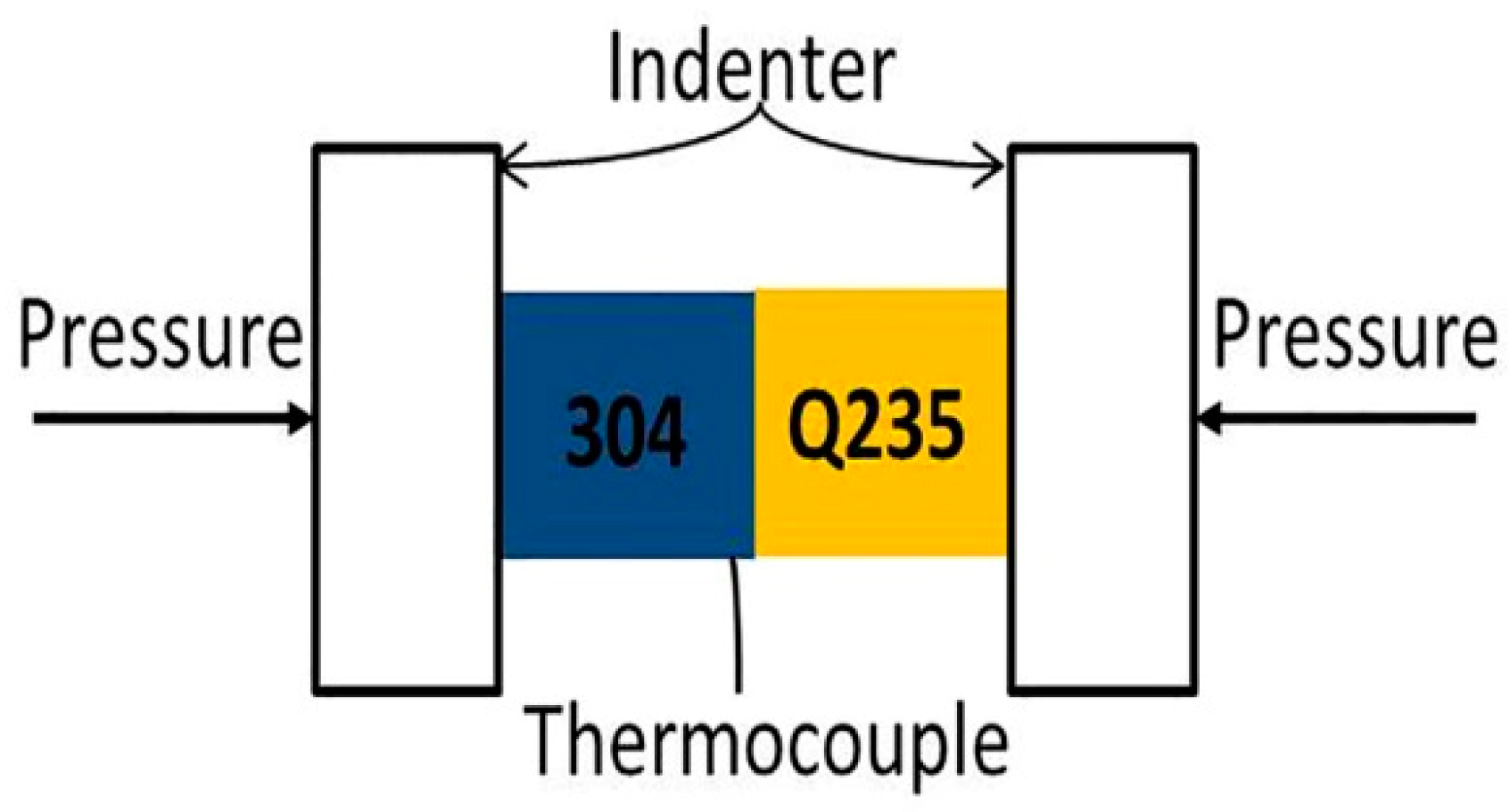
2.1. Bonding Process

The commercial AISI 304 stainless steel and Q235A carbon steel were selected as the raw materials; their chemical compositions are given in Table 1. Both materials were cut into cylindrical specimens with a diameter of 8 mm and length 6 mm. Before the hot uniaxial compression process, the contact surface of the sample was smoothed by grinding and acetone degreasing. Using a Gleeble-3500 thermo-mechanical simulator, the two materials were bonded together. Tantalum sheets were selected to decrease the influence of mutual friction between indenter and the sample in the hot uniaxial compression process.
The experimental process and clamping method of the specimens are shown in Figure 1 and Figure 2 respectively. The specimens were first heated to the deformation temperature at a rate of 5 °C·s−1, and the heat preservation stage was 180 s to avoid the unequal heating of the specimens. The pressure bonding process was carried out in the temperature range of 600, 700, 800, 900, and 1000 °C, and the engineering strain rate range of 0.1, 1, and 10 s−1. The corresponding engineering strains were 10, 20, 30, 40, and 50%. In the process of multi factor experiments, orthogonal experiments are often used instead of comprehensive experiments in order to reduce the scale of experiments. These representative experiments are arranged according to the orthogonal table, which is designed on the basis of the number of research factors and levels. Finally, the experimental results were processed to analyze the influence degree and trend of various factors on the index. In order to study the effect of various bonding parameters on the bonding rate, orthogonal tests were designed with temperature, engineering strain rate, and engineering strain as variables, and a total of 25 groups were used, as shown in Table 2.
A UST 200 immersion ultrasonic “C” scanning detection system (General Electric Company, Boston, MA, USA) was used to detect the unbonded area of the bonding joint, which was composed of a scanning device, ultrasonic signal emission, and a reception unit, signal analysis and pre-processing. The frequency of the probe used is 15 MHz, the focus in water is 30 mm, the diameter at focus is about 0.37 mm, the wave speed is 5800 m/s, and the scanning step length is 0.1 mm. The criteria for judging the unbonded region are as follows: First, an ultrasound “C” scan was performed at a perfect bonding area, which was observed with a microscope to confirm that there is no obvious hole. Then, the height of the first bottom echo was adjusted to 80% of the full scale as a reference sensitivity. The location was identified as an unbonded region when the height of first bottom echo was less than 5% of the full scale, and the defect echo was clearly evident (the height of echo is higher than 5%).

2.2. Heat Preservation

The heat preservation at certain temperatures is often used as a method to improve the interfacial bonding quality of stainless steel/carbon steel composites. However, when the temperature is too high (>900 °C), brittle intermetallic compounds will be formed, resulting in a significant decrease in strength-toughness of the joint [26]. According to the detection results of bonding rates, three groups of samples with different bonding rates were selected for 4 h of heat preservation at 750 °C. Then, the bonding rates of these samples after heat preservation were tested again. Subsequently, all specimens were cut along the axis line, and the joint cross-sections were ground and polished. Microstructural observations were carried out by scanning electron microscopy (SEM) (Carl Zeiss Jena, Heidenheim, Germany) with energy-dispersive spectrometry (EDS).

2.3. Tensile Test

In order to evaluate the effect of the interfacial bonding rate on the mechanical properties, a sample of the same material, with a diameter of 10 mm and length of 45 mm, was selected for hot uniaxial compression. The process was carried out at temperatures of 800, 900, 1000, 1100, and 1200 °C. The effective strain rate was 0.1 s−1 and the corresponding effective strain was 50%. After testing the bonding rate of the samples, the tensile strength was measured using a universal testing machine. The fractured surfaces of the tensile specimens were observed by SEM.

3. Results and Discussion

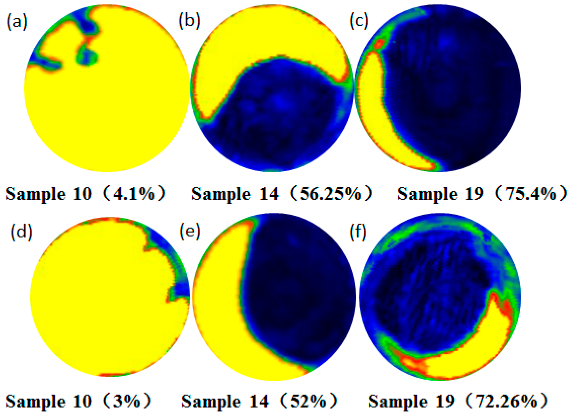
3.1. Effect of Deformation Bonding Parameters on Interfacial Bonding Rate

The scanning images of the interfacial bonding state, acquired after hot uniaxial compression, are shown in Figure 3. According to the echo amplitude (AMP) visualized by ultrasonic “C” scanning, different states can be distinguished using different colors. The blue regions represent the bonding states, the yellow regions represent the unbonded states (the “yellow” spots exist in samples such as 12, 13, 17, 20, and 25 are caused by interference signals from bubbles attached to the surface of samples.), and the green regions represent the semibonding states. The corresponding bonding rates of each specimen are indicated in parentheses below the pictures. As shown in Figure 3, samples 7–10, 11–15, 16–20 and 21–25 were prepared at temperatures of 700 °C, 800 °C, 900 °C and 1000 °C respectively. It is indicated that the effect of temperature on the bonding rate is obvious. No bonding areas exist between the interfaces at 600 °C. A certain degree of bonding occurs up to an engineering strain rate of more than 30% at 700 °C. This indicates that the critical temperature for large-area bonding between AISI304 stainless steel and Q235A carbon steel is approximately 700 °C. With the increase in temperature, materials are easier to deform, and the full integration of the interface can be achieved at 1000 °C. Moreover, the engineering strain also has an important effect on the bonding rate. With an increase in the reduction, the real contact area between the materials increases. This is the basis of the formation of a bonding area.
The metallurgical bonding over the entire interface does not occur simultaneously. Owing to the influences of surface morphology and parallelism of the sample axis, the bonding first occurs somewhere on the interface. As the reduction increases, the real contact area between the metal interfaces increases gradually, and finally, the bonding region extends over the whole interface.
Using a balanced experimental design to arrange the experiment in an orthogonal design, the overall results are mainly understood through the analysis of partial experimental results. The influencing degrees of deformation temperature, engineering strain, and engineering strain rate on the bonding rate are studied using the orthogonal analysis. The calculation results of the range are shown in Table 3. It is clear that the effect of the temperature on the bonding rate is the most significant, followed by the effective strain; that of the effective strain rate is the least.
The relationship between the various factors and bonding rate are shown in Figure 4. The horizontal coordinates of each factor are taken as the abscissa, and the average of the bonding rate is the ordinate. It is more intuitive that the experimental indicators change with the change in the level of factors. It can be concluded that the influence of temperature on the bonding rate is the largest and is positively correlated, while with the increase of engineering strain rate, the bonding rate increases first and then decreases. The optimal bonding quality can be obtained when the strain rate is up to 1 s−1. Additionally, with the increase of strain, the bonding rate decreases first and then increases.

3.2. Effect of Heat Preservation on the Interfacial Bonding Rate

Heat preservation is often used to eliminate gap defects in the interface, which is one of the methods used to improve the quality of the joint. Samples 10, 14, and 19 were selected for 2 h of heat preservation under 750 °C. The bonding rates are 4.1%, 56.25%, and 75.4% respectively. The bonding rates of each specimen before and after heat treatment are shown in Figure 5. The observations indicate that the bonding rate decreases after heat preservation. Liu et al. [27] noted that the thermal residual stress is produced owing to the difference in thermal expansion coefficients between the materials during the fabrication processes of metal-matrix composites. In this study, the decrease in bonding rates is mainly because of the generation of thermal stress in the heat treatment process.
In order to study the effect of heat preservation on the thicknesses of the diffusion layers, all samples (include samples 10, 14, and 19) were selected to observe the concentrations of the typical elements Fe, Cr, and Ni near the interface. Partial results are shown in Figure 6. For the specimens without thermal insulation treatment, the thicknesses of the diffusion layers are 2–3 µm, regardless of the deformation temperature. However, for the samples treated by heat preservation, the thicknesses of the diffusion layers are approximately 7 µm. Therefore, it can be concluded that a sufficiently high temperature and long time are the necessary conditions for deep diffusion.
The process of deformation bonding has been widely studied by many researchers, and is usually considered to be divided into three stages. In the first stage, close contact is produced in most areas of the interface under the yield and creep deformation mechanism. In the second stage, many voids disappear, mainly by diffusion and grain boundary migration, and the migration of grain boundaries leaves many remaining voids. In the third stage, the interface voids completely disappear with the volume diffusion [28]. Through this research we can conclude that the interfacial bonding rate is mainly formed in the first stage. Because the mutual contact time during the deformation process is very short, only shallow diffusion occurs at the interface between stainless steel and carbon steel. In the second and third stages, after a period of thermal insulation treatment, the deep diffusion at the interface begins to occur.

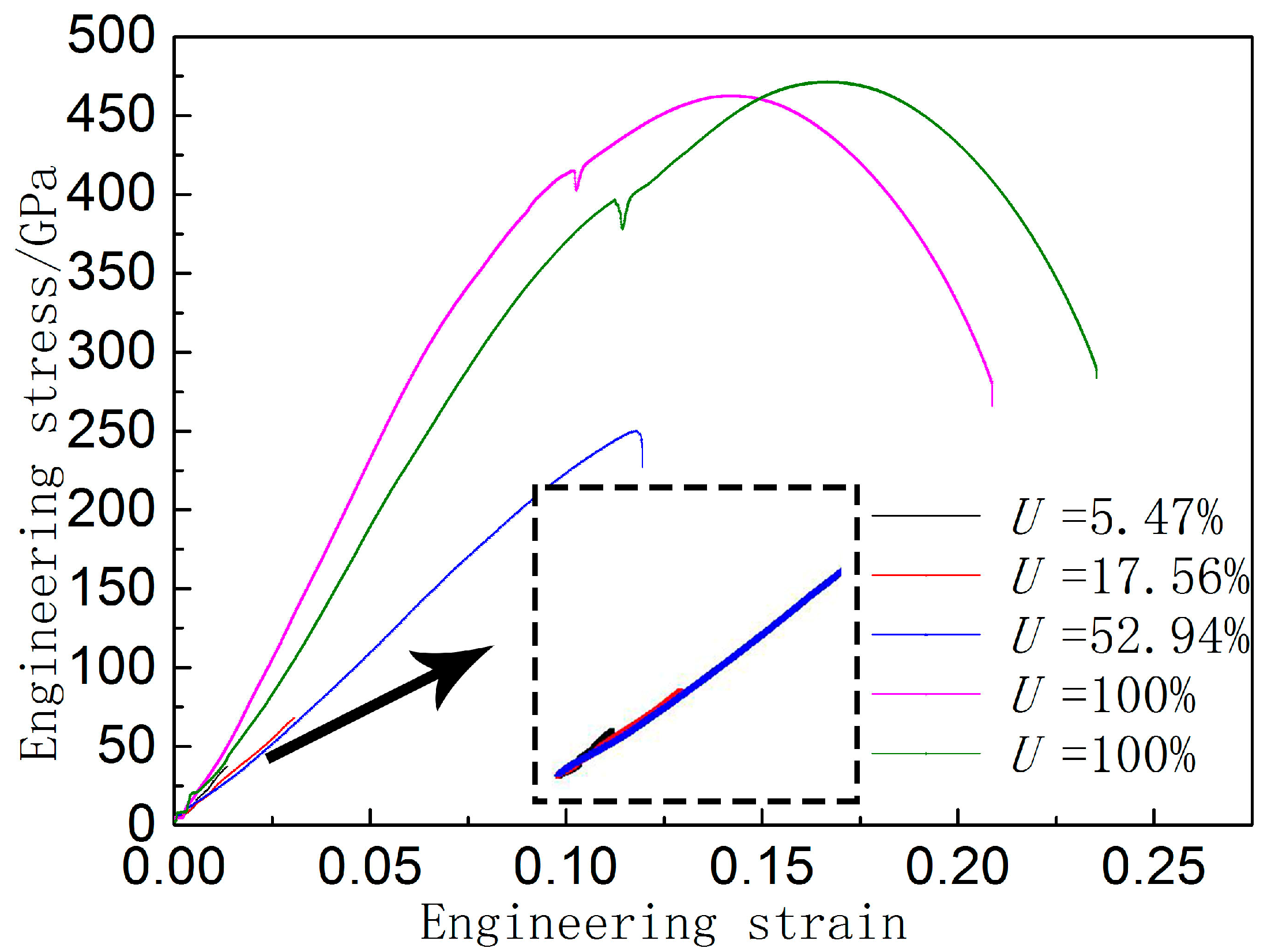
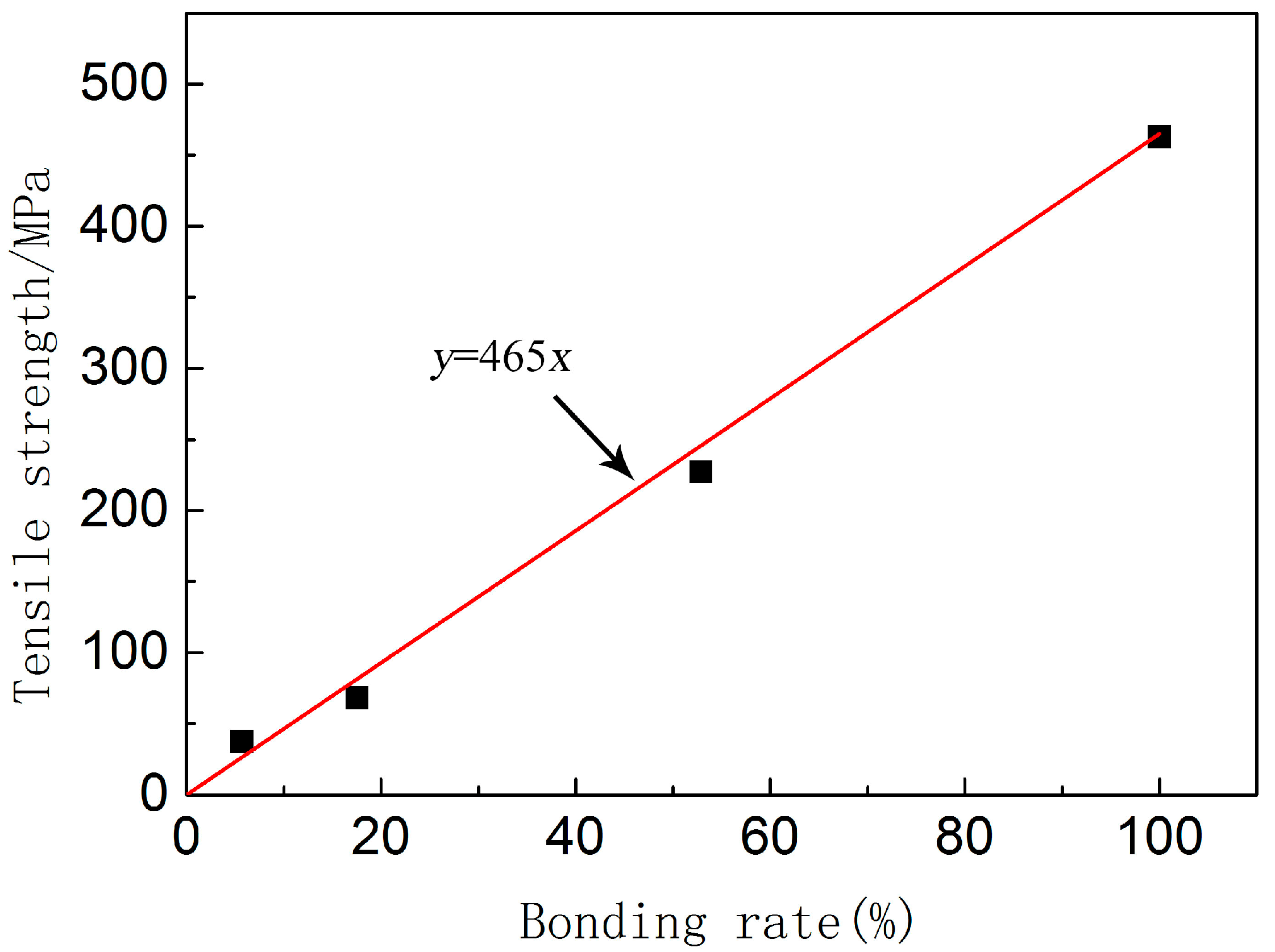
3.3. Relationship between Bonding Rate and Mechanical Properties

The specimens with different bonding temperatures after tensile fracture are shown in Figure 7. The corresponding bonding rates are 5.74%, 17.56%, 52.94%, 100%, 100% respectively. Through previous analysis, it can be concluded that the thickness of diffusion layers at different deforming temperatures is equal. The difference in bonding rates is the only difference factor for the bonding states for these groups.
There was no obvious plastic deformation at 800, 900, or 1000 °C. For the samples at 800 °C, the obvious crescent shaped metal is visible at the edge of the interface. As the deforming temperature increases to 900 and 1000 °C, the area expands. The concentrations of typical elements in this area are shown in Figure 8. The part of the metal adhered on the surface of stainless steel is mainly carbon steel. This indicates that the tensile strength of the diffusion layer and both sides of the metal are higher than that of the carbon steel matrix. A clearly evident necking phenomenon of the carbon steel occurs at 1100 and 1200 °C. Obvious plastic deformation is observed before fracture. Moreover, the fracture positions of the specimens are all on the side of the carbon steel matrix. A dark gray cup cone fracture is observed, which is a typical microporous aggregation ductile fracture.
Figure 9 shows the stress-train curves of the samples with different bonding rates. It can be seen that the bonding rate has a significant influence on the tensile mechanical properties of the bimetal material. In the process of stretching, there is no obvious yield platform in the tensile process. When the bonding rate is high (Bonding rate of 100%), the material becomes elastically deformed, undergoes plastic deformation, and finally breaks down. The material is broken down from the carbon steel matrix, and the tensile strength of the material is equal to the strength of the carbon steel. When the bonding rate is low (Bonding rate of 5.47%, 17.56%, 52.94%), there is almost no plastic deformation in the tensile process, and fractures occur in elastic stage. The soft carbon steel part is torn at the interface and the tensile strength of the material increases with the increase of the bonding rate. Magnification diagrams of stress–strain curves of composite specimens under 5.74%, 17.56%, and 52.94% are shown in the dashed frame. Interestingly, the three groups of specimens exhibited similar mechanical behavior during the tensile process. We assume that the strength of the composite is only related to the bonding rate and the strength of the relatively soft material. Therefore, the tensile strength of the composite can be approximately considered as the product of the tensile strength and the bonding rate of the relatively soft material. The equation is formulated as follows:
σ b = σ s b × U
where σ b is the tensile strength of the composite, σ s b is the tensile strength of the softest part of material, and U is the bonding rate of the interface.
The relationship between the tensile strength and bonding rate of the joint is shown by the red line in Figure 10. The coefficient of the equation is the tensile strength of the carbon steel, which can be approximately obtained from Figure 9. The black point is the tensile strength under various bonding rates. It is clear from Figure 10 that the experimental results agree well with these assumptions. The bonding rate has a linear positive correlation with the tensile strength of the material.
The fracture surface of the composite after tensile fracture is shown in Figure 11. A river pattern is visible on the fracture surfaces at a bonding rate of 5.74% (Figure 11a,b). The specimen exhibits obvious transgranular fractures. The fracture source is located at the junction of the unbonded and bonded areas of the interface. When the bonding rate reaches 17.56%, most of the fracture area is still a cleavage fracture. However a small number of wine-like dimples appear (Figure 11c,d). When the bonding rate reaches 52.94%, the ductile fracture zone becomes larger, and the dimples becomes larger and deeper, indicating that the fracture toughness is strengthened. When the bonding rate reaches 100%, the crack source is located in the interior of the carbon steel, which indicates a typical microporous agglomeration fracture with high toughness.

4. Conclusions

In this paper, the evolution of the compound interface in a deformation bonding process and heat preservation, and the effect of bonding rate on the mechanical properties of 304 stainless steel/Q235 carbon steel are investigated. The following specific conclusions are drawn:
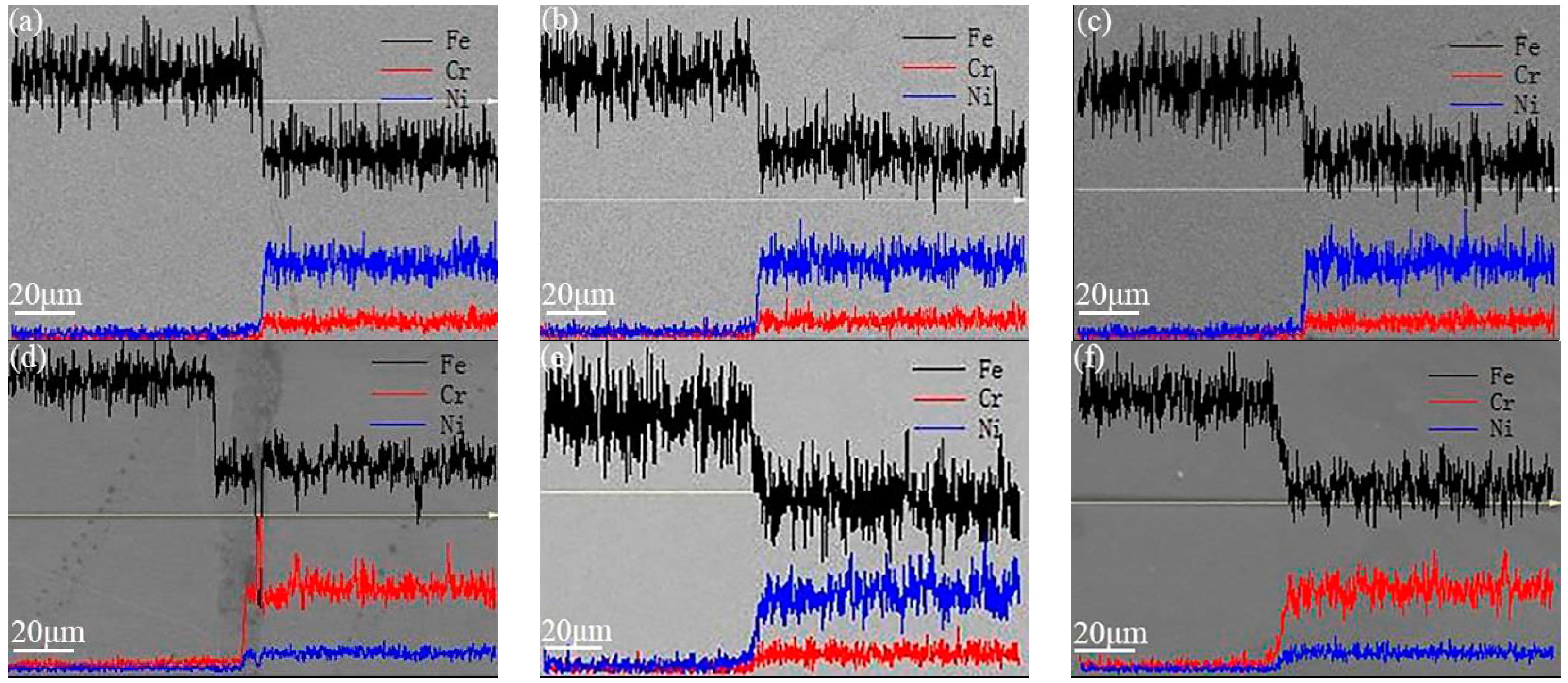
  • During the deformation bonding production of stainless-steel and carbon-steel joints, the deformation temperature has the most significant linear correlation with bonding rate, but has little influence on the thickness of the diffusion layer. Only shallow diffusion can be realized, owing to the short contact time.
  • The thickness of the diffusion layer can be improved by the heat preservation treatment, whereas the bonding rate of the joint decreases slightly due to the difference in thermal expansion coefficients between two materials.
  • The interfacial bonding rate of the joint has a great influence on the mechanical properties of stainless steel/carbon steel composite. It is found that the bonding strength between the diffusion layer and both sides of the metal is higher than that of the carbon steel matrix, and the strength of the composite is only related to the bonding rate and the strength of the relatively soft material.
  • The interfacial bonding rate also has a great influence on the failure mode of stainless steel/carbon steel. When the bonding rate is low, the crack initiates at the junction of the unbonded and bonded areas of the interface and extends to the binding region. When the bonding rate is high, no obvious gap occurs at the interface, and the crack source is located in the interior of the carbon steel. Moreover, with the increase in bonding rate, the fracture mode changes from cleavage brittle fracture, to ductile-brittle mixed-mode fracture, and then to ductile fracture.

Author Contributions

Qingdong Zhang conceived the research idea; Shuo Li wrote the manuscript and analyzed the data; Jiyang Liu, Boyang Zhang and Yanan Wang assisted in the experiments and prepared the test specimens. Li-Yuan Zhang supervised the findings of this work.

Funding

This research was funded by [National Natural Science Foundation of China] grant number [51575040].

Acknowledgments

This work was supported by National Natural Science Foundation of China (No. 51575040).

Conflicts of Interest

The authors declare no conflict of interest.

References

  1. Chen, L.; Yang, Z.; Jha, B.; Xia, G.; Stevenson, J.W. Clad metals, roll bonding and their applications for SOFC interconnects. J. Power Sources 2005, 152, 40–45. [Google Scholar] [CrossRef]
  2. Ju, Y.J.; Sun, I.H. Effect of heat treatment on tensile deformation characteristics and properties of Al3003/STS439 clad composite. Mater. Sci. Eng. A 2014, 596, 1–8. [Google Scholar]
  3. Knezevic, M.; Jahedi, M.; Korkolis, Y.P.; Beyerlein, I.J. Material-based design of the extrusion of bimetallic tubes. Comput. Mater. Sci. 2014, 95, 63–73. [Google Scholar] [CrossRef]
  4. Shen, W.N.; Feng, L.J.; Feng, H.; Cao, Y.; Liu, L.; Cao, M.; Ge, Y.F. Preparation and characterization of 304 stainless steel/q235 carbon steel composite material. Results Phys. 2017, 7, 529–534. [Google Scholar] [CrossRef]
  5. Gomez, X.; Echeberria, J. Microstructure and mechanical properties of carbon steel A210/superalloy Sanicro 28 bimetallic tubes. Mater. Sci. Eng. A 2003, 348, 180–191. [Google Scholar] [CrossRef]
  6. Masahashi, N.; Watanabe, S.; Nomura, N.; Semboshi, S.; Hanada, S. Laminates based on an iron aluminide intermetallic alloy and a CrMo steel. Intermetallics 2005, 13, 717–726. [Google Scholar] [CrossRef]
  7. Kurt, B. The interface morphology of diffusion bonded dissimilar stainless steel and medium carbon steel couples. J. Mater. Process. Technol. 2007, 190, 138–141. [Google Scholar] [CrossRef]
  8. Velmurugan, C.; Senthilkumar, V.; Sarala, S.; Arivarasan, J. Low temperature diffusion bonding of Ti-6Al-4 V and duplex stainless steel. J. Mater. Process. Technol. 2016, 234, 272–279. [Google Scholar] [CrossRef]
  9. Sheng, G.M.; Huang, J.W.; Qin, B.; Zhou, B.; Qiu, S.Y.; Li, C. An experimental investigation of phase transformation superplastic diffusion bonding of titanium alloy to stainless steel. J. Mater. Sci. 2005, 40, 6385–6390. [Google Scholar] [CrossRef]
  10. Zotti, L.A.; Sanvito, S.; O’Regan, D.D. A simple descriptor for energetics at fcc-bcc metal interfaces. Mater. Des. 2018, 142, 158–165. [Google Scholar] [CrossRef]
  11. Weng, S.Y.; Ning, H.M.; Hu, N.; Yan, C.; Fu, T.; Peng, X.H.; Fu, S.Y.; Zhang, J.Y.; Xu, C.H.; Sun, D.Y.; et al. Strengthening effects of twin interface in Cu/Ni multilayer thin films—A molecular dynamics study. Mater. Des. 2016, 111, 1–8. [Google Scholar] [CrossRef]
  12. Lee, T.H.; Lee, Y.J.; Park, K.T.; Nersisyan, H.H.; Jeong, H.G.; Lee, J.H. Controlling Al/Cu composite diffusion layer during hydrostatic extrusion by using colloidal Ag. J. Mater. Process. Technol. 2013, 213, 487–494. [Google Scholar] [CrossRef]
  13. Shao, X.; Guo, X.; Han, Y.; Lu, W.; Qin, J.; Zhang, D. Characterization of the diffusion bonding behavior of pure Ti and Ni with different surface roughness during hot pressing. Mater. Des. 2015, 65, 1001–1010. [Google Scholar] [CrossRef]
  14. Chen, S.; Ke, F.; Min, Z.; Bai, Y. Atomistic investigation of the effects of temperature and surface roughness on diffusion bonding between Cu and Al. Acta Mater. 2007, 55, 3169–3175. [Google Scholar] [CrossRef]
  15. Ahmed, T.; Belova, I.V.; Murch, G.E. Finite Difference Solution of the Diffusion Equation and Calculation of the Interdiffusion Coefficient using the Sauer-Freise and Hall Methods in Binary Systems. Procedia Eng. 2015, 105, 570–575. [Google Scholar] [CrossRef]
  16. Wang, T.M.; Cao, F.; Zhou, P.; Kang, H.J.; Chen, Z.N.; Fu, Y.N.; Xiao, T.Q.; Huang, W.X.; Yuan, Q.X. Study on diffusion behavior and microstructural evolution of Al/Cu bimetal interface by synchrotron X-ray radiography. J. Alloys Compd. 2014, 616, 550–555. [Google Scholar] [CrossRef]
  17. Sun, C.Y.; Li, L.; Fu, M.W.; Zhou, Q.J. Element diffusion model of bimetallic hot deformation in metallurgical bonding process. Mater. Des. 2016, 94, 433–443. [Google Scholar] [CrossRef]
  18. Sun, C.Y.; Cong, Y.P.; Zhang, Q.D.; Fu, M.W.; Li, L. Element diffusion model with variable coefficient in bimetallic bonding process. J. Mater. Process. Technol. 2017, 253, 99–108. [Google Scholar] [CrossRef]
  19. Ben, B.S.; Ben, B.A.; Ratnam, C.; Yang, S.H. Ultrasonic based method for damage identification in composite materials. Int. J. Mech. Mater. Des. 2012, 8, 297–309. [Google Scholar] [CrossRef]
  20. Juan, C.; Nicolas, B.; Manuel, C.; Sergio, C.; Guillermo, R. A multilevel Bayesian method for ultrasound-based damage identification in composite laminates. Mech. Syst. Signal Process. 2017, 88, 462–477. [Google Scholar]
  21. Zhou, H.M.; Liu, G.W. A model-based ultrasonic quantitative evaluation method for bonding quality of multi-layered material. Measurement 2012, 45, 1414–1423. [Google Scholar] [CrossRef]
  22. Luan, Y.L.; Sun, T.; Feng, J.C.; Gang, T. Ultrasonic evaluation of TiAl and 40Cr diffusion bonding quality based on time-scale characteristics extraction. NDT & E Int. 2011, 44, 786–796. [Google Scholar]
  23. Suresh Kumar, S.; Krishnamoorthi, J.; Ravisankar, B.; Balusamy, V. Assessing quality of diffusion bonded joints with interlayer using ultrasonic/ultrasound. J. Mater. Process. Technol. 2017, 242, 139–146. [Google Scholar] [CrossRef]
  24. Suresh Kumar, S.; Ravisankar, B. An evaluation of quality of joints in two dissimilar metals diffusion bonded using ultrasonic. Mater. Manuf. Process. 2016, 31, 2084–2090. [Google Scholar] [CrossRef]
  25. Lesuer, D.R.; Syn, C.K.; Sherby, O.D.; Wadsworth, J.; Lewandowski, J.J.; Hun, W.H. Mechanical behaviour of laminated metal composites. Mater. Rev. 1996, 41, 169–197. [Google Scholar] [CrossRef]
  26. Wang, D.W.; Xiu, S.C. Effect of bonding temperature on the interfacial microstructure and performance of mild steel/austenite stainless steel diffusion-bonded joint. Acta Metall. Sin. 2017, 53, 567–574. [Google Scholar] [CrossRef]
  27. Liu, H.T.; Sun, L.Z. Effects of thermal residual stresses on effective elastoplastic behavior of metal matrix composites. Int. J. Solids Struct. 2004, 41, 2189–2203. [Google Scholar] [CrossRef]
  28. Dave, V.R.; Beyerlein, I.J.; Hartman, D.A.; Barbieri, J.M. A probabilistic diffusion weld modeling framework. Weld. J. 2003, 82, 170–178. [Google Scholar]
Figure 1. Experimental process of deformation bonding.
Metals 08 00329 g001
Figure 2. Clamping method of specimens.
Metals 08 00329 g002
Figure 3. Detection results of bonding rate under different bonding parameters.
Metals 08 00329 g003
Figure 4. Influence trend of bonding parameters on the bonding rate.
Metals 08 00329 g004
Figure 5. Test results of bonding rate before heat preservation (ac) and after heat preservation (df).
Metals 08 00329 g005
Figure 6. EDS (energy-dispersive spectrometry) profiles of Fe, Cr, and Ni across the interface of the stainless steel/carbon steel: partial samples before heat preservation (ac), and three samples after heat preservation (df).
Metals 08 00329 g006
Figure 7. The bonding rates of specimens at different deformation temperatures and corresponding fracture features after tensile test.
Metals 08 00329 g007
Figure 8. Concentration distribution of elements at junction.
Metals 08 00329 g008
Figure 9. Engineering stress–stain curves of the samples with different bonding rates.
Metals 08 00329 g009
Figure 10. Relationship between bonding rate and tensile strength (■ symbols indicate the experimental values and the red line indicates the hypothetical relationship).
Metals 08 00329 g010
Figure 11. Magnified fracture features of 304 stainless steel/Q235 carbon steel at bonding rate of (a,b) 5.74%; (c,d) 17.56%; (e,f) 52.94%; (g) 100%, and (h) 100%.
Metals 08 00329 g011
Table 1. Chemical composition of AISI304 and Q235A (mass fraction/%).
MaterialCrNiCSiMnPSFe
AISI30418.978.860.041.002.000.0350.03Bal
Q235A--0.220.300.430.040.05Bal
Table 2. The orthogonal experiment table.
Number12345678910111213
Temperature/°C600600600600600700700700700700800800800
Engineering strain rate/s−10.10.515100.10.515100.10.51
Engineering strain0.10.20.30.40.50.20.30.40.50.10.30.40.5
Number141516171819202122232425-
Temperature/°C600600600600600700700700700700800800-
Engineering strain rate/s−15100.10.515100.10.51510-
Engineering strain0.10.20.40.50.10.20.30.50.10.20.30.4-
Table 3. Range value of bonding parameters.
Bonding ParametersTemperatureEngineering Strain RateEngineering Strain
Range value10019.9527.45

